EP1579384B1 - Konfigurationsverfahren für eine 3d-eingabevorrichtung, verfahren zur neukonfiguration einer 3d-eingabevorrichtung, verfahren zur erkennung des tragens der 3d-eingabevorrichtung und gerät dafür - Google Patents
Konfigurationsverfahren für eine 3d-eingabevorrichtung, verfahren zur neukonfiguration einer 3d-eingabevorrichtung, verfahren zur erkennung des tragens der 3d-eingabevorrichtung und gerät dafür Download PDFInfo
- Publication number
- EP1579384B1 EP1579384B1 EP03779023.5A EP03779023A EP1579384B1 EP 1579384 B1 EP1579384 B1 EP 1579384B1 EP 03779023 A EP03779023 A EP 03779023A EP 1579384 B1 EP1579384 B1 EP 1579384B1
- Authority
- EP
- European Patent Office
- Prior art keywords
- information
- finger
- processing unit
- input
- user
- Prior art date
- Legal status (The legal status is an assumption and is not a legal conclusion. Google has not performed a legal analysis and makes no representation as to the accuracy of the status listed.)
- Expired - Lifetime
Links
Images


Classifications
-
- G—PHYSICS
- G06—COMPUTING OR CALCULATING; COUNTING
- G06F—ELECTRIC DIGITAL DATA PROCESSING
- G06F3/00—Input arrangements for transferring data to be processed into a form capable of being handled by the computer; Output arrangements for transferring data from processing unit to output unit, e.g. interface arrangements
- G06F3/01—Input arrangements or combined input and output arrangements for interaction between user and computer
- G06F3/03—Arrangements for converting the position or the displacement of a member into a coded form
- G06F3/033—Pointing devices displaced or positioned by the user, e.g. mice, trackballs, pens or joysticks; Accessories therefor
- G06F3/0346—Pointing devices displaced or positioned by the user, e.g. mice, trackballs, pens or joysticks; Accessories therefor with detection of the device orientation or free movement in a 3D space, e.g. 3D mice, 6-DOF [six degrees of freedom] pointers using gyroscopes, accelerometers or tilt-sensors
-
- G—PHYSICS
- G06—COMPUTING OR CALCULATING; COUNTING
- G06F—ELECTRIC DIGITAL DATA PROCESSING
- G06F3/00—Input arrangements for transferring data to be processed into a form capable of being handled by the computer; Output arrangements for transferring data from processing unit to output unit, e.g. interface arrangements
- G06F3/01—Input arrangements or combined input and output arrangements for interaction between user and computer
- G06F3/011—Arrangements for interaction with the human body, e.g. for user immersion in virtual reality
- G06F3/014—Hand-worn input/output arrangements, e.g. data gloves
-
- G—PHYSICS
- G06—COMPUTING OR CALCULATING; COUNTING
- G06F—ELECTRIC DIGITAL DATA PROCESSING
- G06F3/00—Input arrangements for transferring data to be processed into a form capable of being handled by the computer; Output arrangements for transferring data from processing unit to output unit, e.g. interface arrangements
- G06F3/01—Input arrangements or combined input and output arrangements for interaction between user and computer
- G06F3/02—Input arrangements using manually operated switches, e.g. using keyboards or dials
- G06F3/023—Arrangements for converting discrete items of information into a coded form, e.g. arrangements for interpreting keyboard generated codes as alphanumeric codes, operand codes or instruction codes
- G06F3/0233—Character input methods
Definitions
- the present invention relates to a method for configuring a three-dimensional (3D) information input device, a method for reconfiguring the 3D information input device, a method for recognizing wearing of the 3D information input device, and an apparatus thereof.
- Korean Patent Publication No. 1998-36079 discloses a glove interface device for inputting digital data, which includes a glove, which compares digital sensors and 3D sensors on fingers, for outputting digital data indicating touch status between fingers, position and rotation of a hand and a processor for detecting information including the touch status between fingers, the position and rotation of the hand based on the digital data received from the glove and providing the detected information to a host computer.
- Korean Patent Publication No. 1998-36077 discloses a digital glove input device, which includes a sensor block, placed on the fingers, senses a finger crooking signal generated with respect to a user's finger crooking and detects finger crooking information in response to the finger crooking signal.
- the digital glove input device also includes a control block which generates a motion control signal based on the detected finger crooking information.
- Japanese Patent Publication No. 1996-272520 discloses glove instruction call-originating equipment, which includes an extension/contraction detecting sensor and a movement recognizing part.
- the sensor is attached to the finger part, the back part, and the palm part of a glove, and simultaneously inputs signals of respective sensors.
- the movement recognizing part continuously processes a group of input signal patterns and synthesizes the provided results so as to judge and decide on a certain instruction.
- US 2002/0130844 A1 refers to a system and method implementing a virtual reality (VR) keyboard, wherein the VR keyboard system and method receive a VR glove position, generate a corresponding key code from the VR glove position using a predetermined mapping, and send the key code to an application program as a key input corresponding to a keyboard and/or keypad entry of data and/or a command.
- VR virtual reality
- Skill level and method of inputting information through a general keyboard vary with respect to users. Some users may input information through a QWERTY keyboard using only the two index fingers of both hands, or four or six fingers of both hands. Others skilled in the QWERTY keyboard may input information using all the fingers of both hands.
- the skill level and method for inputting information in 3D space using a hand-attached device vary with respect to users. Therefore, in an input device including ten finger elements for all fingers of both hands, some users may want to use only four or six finger elements of both hands. Some users may be-forced to use only several finger elements due to mechanical failures in the rest of the finger elements.
- Adaptive self-reconfiguration may be needed in situations in which a user wants to select which finger elements to use or is forced to use only a few of the finger elements due to mechanical failures in the reset of the finger elements.
- Adaptive self-reconfiguration may also be needed in situations in which a user wants to deactivate a specific finger element when wearing the 3D input device, so as to change a key array of a keyboard in user or to change a language.
- a recognizing unit of the finger element is unable to recognize the finger device.
- the recognizing unit is designed to sequentially recognize sensors X1, X2, X3, and X4.
- the sensor X1 malfunctions, it continuously circulates a loop and then cannot determine whether the user is wearing the finger elements and the positions of the finger elements. Therefore, the 3D input device cannot be entirely used even when only one finger element is malfunctioning
- the present invention is defined according to the method of claim 1 and the apparatus of claim 7.
- FIG. 1A illustrates an example of a three-dimensional (3D) input device 100, according to the present invention.
- the 3D input device 100 includes an information input finger device 110 (hereinafter referred to as a finger device), a signal-processing device 120, and a computer 150.
- FIG. 1 shows the entire configuration necessary for information input. However, hereinafter, the configuration of the 3D input device 100 will be described as it relates to initialization of the 3D input device 100, i.e., the operation of adaptively configuring or reconfiguring the 3D input device 100.
- the finger device 110 includes a first sensor (X1) 111, a second sensor (X2) 112, a third sensor (X3) 113, and a fourth sensor (X4) 114, as a sensing means for sensing finger movements.
- a connection unit 115 that connects the finger device 110 with a signal-processing device 120.
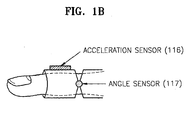
- Each sensor 111, 112, 113, or 114 may include an acceleration sensor 116 and an angle sensor 117 as shown in FIG. 1B .
- a signal outputted from the acceleration sensor 116, a sensing one on finger movement acceleration, can be used as a clock signal, namely an information input signal.
- a signal outputted from the angle sensor 117, a sensing one on an angle between the first and second knuckles of a finger, can be used as an information selection signal.
- the sensors are not limited to those described above.
- the present invention may include any other kind of sensors capable of sensing the finger's movement to output signals for information input or information selection.
- a sensor outputting a digital signal e.g., an inertial sensor, or a sensor outputting an analog signal, e.g., a potentiometer, a Giant Magnetoresistive (GMR) sensor, an optical sensor, an on/off switch, or a pressure sensor
- a digital signal e.g., an inertial sensor
- a sensor outputting an analog signal e.g., a potentiometer, a Giant Magnetoresistive (GMR) sensor, an optical sensor, an on/off switch, or a pressure sensor
- the signal-processing device 120 receives and processes a signal outputted from the sensors 111, 112, 113, and 114 of the finger device 110.
- the signal-processing device 120 may be mounted on the back of a user's hand.
- the signal-processing device 120 includes a pre-processing unit 130 and a signal-processing unit 140.
- the pre-processing unit 130 receives the signals outputted from the finger device 110 via the connection unit 115through a cable or air in a wired or wireless manner, and recognizes the finger device 110 worn by the user.
- the signal-processing unit 140 receives finger device recognition information outputted from the pre-processing unit 130, self-configures the signal-processing device 120 based on the finger device recognition information, processes finger movement information outputted from the sensors 111, 112, 113, and 114 based on a selected algorithm, extracts movement characteristic information from the finger movement information, and transmits the movement characteristic information to a device driver 160 of the computer 150 through a connection, such as a Universal Serial Bus (USB).
- self-configuration of the signal-processing unit 140 refers to self-configure the firmware, namely algorithm. For example, if the finger device recognition information is for three fingers, the signal-processing unit 140 self-configures an algorithm in order to process three signals outputted from three sensors.
- the computer 150 includes the device driver 160 and the application 170.
- the device driver 160 configures itself based on basic set-up information and the movement characteristic information received from the signal-processing unit 140 and then reconfigures itself based on reset information received from the application 170.
- Basic set-up information denotes input scenario information including a language in use or key array of a keyboard, etc.
- the application 170 receives the basic set-up information and the movement characteristic information from the device driver 160, transmits a soft keyboard to an output device (not shown) based on the received basic set-up information, interprets the received movement characteristic information, and outputs input information items based on the interpreted movement characteristic information to the output device (not shown) or another application (not shown).
- the application 170 allows the user to reconfigure the 3D input device 100 through a user interface.
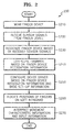
- FIG. 2 is a schematic flowchart 200 of initializing a configuration of the 3D input device 100, according to the present invention.
- step S210 a user wears the finger device 110.
- step S220 sensor signals are output from the sensors 111, 112, 113, and 114 included in the finger device 110.
- the pre-processing unit 130 receives sensor signals.
- the pre-processing unit 130 recognizes whether the user is wearing the finger device 110 and recognizes the position of the finger device 110, based on the received sensor signals (step S230) and transmits finger device recognition information with finger movement information outputted from the sensors 111, 112, 113, and 114, to the signal-processing unit 140.
- the signal-processing unit 140 configures firmware based on the finger device recognition information in step S240, processes the finger movement information, and transmits movement characteristic information to the device driver 160.
- the device driver 160 configures itself based on the movement characteristic information and basic set-up information (step S250).
- the application 170 outputs a soft keyboard on which positions of fingers are displayed to the output device (not shown) according to the configuration information of the device driver 160 (step S260), interprets the movement characteristic information of the finger device 110, and performs information input procedure (step S270).
- FIG. 3A is a detailed block diagram of the pre-processing unit 130 of FIG. 1A
- FIG. 3B is a flowchart of initialization operations in the pre-processing unit 130 of FIG. 3A for configuration of the 3D input device, according to the present invention.
- FIGS. 3A and 3B configuration and operation of the pre-processing unit 130 will be described.
- the pre-processing unit 130 of FIG. 3A includes a first port 131, a second port 132, a third port 133, and a fourth port 134 that receive sensing information from the finger device 110, a port change recognizing and storing unit 135 that recognizes changes between previous and current times in each port, an output value calculating unit 136 that calculates output values using values stored in the port change recognizing and storing unit 135, and an output value transmitting unit 137 that transmits the calculated outputs to the signal-processing unit 140.
- the pre-processing unit 130 initializes hardware and software therein (step S310).
- the pre-processing unit 130 receives the sensor signals from the first sensor 111, the second sensor 112, the third sensor 113, and the fourth sensor 114 of the finger device 110 (step S320).
- the sensor signals include signals for information item selections and signals for the information input.
- the information item selection denotes selecting an information item among a plurality of information items, for example, selecting a character key among a plurality of character keys.
- the information input denotes clicking the selected character key.
- step S330 it is recognized whether the user is wearing the finger device 110 and the finger positions of the finger device 110 using the received sensor signals.
- the sensor signals used to recognize the finger device 110 may be the signals for the information item selections or the signals for the information input. However, hereinafter, the sensor signals means the information input signals output from the acceleration sensor 116.
- the finger device recognition information refers to which sensor information about sensor usage and finger position. Step S330 may be performed by the port change recognizing and storing unit 135 and the output calculating unit 136, which will be described in detail later.
- the output transmitting unit 137 transmits the finger device recognition information and sensor signals to the signal processing unit 140 (step S340).
- the finger device recognition information denotes information recognized by the pre-processing unit 130
- the sensor output signals denote the finger movement information of the finger device 110.
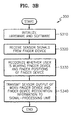
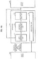
- FIG. 4A is a detailed block diagram of the signal-processing unit 140 of FIG. 1A
- FIG. 4B is a flowchart of operations in the signal-processing unit 140 of FIG. 4A for initializing configuration of the 3D information input device, according to the present invention.
- FIGS. 4A and 4B configuration and operation of the signal-processing unit 140 of the signal-processing device 120 will be described.
- the signal-processing device 140 of FIG. 4A includes a finger device self-configuring unit 141 and a finger movement information processing unit 142.
- the finger device self-configuring unit 141 receives the finger movement information and the finger device recognition information from the pre-processing unit 130, and self-configures the finger device 110 based on the received finger device recognition information.
- the finger movement information processing unit 142 extracts movement characteristic information by processing the received finger movement information based on an algorithm of the self-configured finger device 110.
- the signal-processing unit 140 initializes its hardware and software in step S410. After the finger device self-configuring unit 141 receives the finger device recognition information and the sensor signals from the pre-processing unit 130 (step S420), the finger device self-configuring unit 141 deactivates algorithms on the unworn sensors and configures the firmware subsequently based on the received finger device recognition information (step S430). For example, if the finger device self-configuring unit 141 receives finger device recognition information indicating the user is wearing the second 112, third 113, and fourth 114 sensors, the finger device self-configuring unit 141 sets up algorithms used to process the signals received from the second 112, third 113, and fourth 114 sensors and deactivates the other algorithms.
- the finger movement information processing unit 142 executes the signal processing algorithms on the signals output from the worn sensors based on the configured firmware. That is, the finger movement information processing unit 142 inputs the received sensor signals to the algorithms on the second 112, third 113 and fourth 114 sensors, calculates the selection information obtained by the operation of the finger device 110, and determines whether operations of the finger device 110 correspond to information input. For example, the finger movement information processing unit 142 calculates the positions of fingers to determine which information items are selected by the corresponding fingers, determines keys which correspond to the calculated positions of fingers, or determines whether the operations of the finger device 110 correspond to information input by evaluating whether signal values for the information input have crossed a predetermined threshold. The calculation results of the selection information and determination results to input operations become the movement characteristic information.
- the finger movement information processing unit 142 transmits the movement characteristic information, and the previously received finger device recognition information to the device driver 160 of the computer 150 in step S450.
- the signal-processing unit 140 may use USB to transmit the movement characteristic information to the device driver 160 of the computer 150.
- FIG. 5A is a detailed block diagram of the device driver 160 of FIG. 1A
- FIG. 5B is a flowchart of operations in the device driver 160 of FIG. 5A for initializing the configuration of the 3D input device 100, according to the present invention.
- FIGS. 5A and 5B configuration and operation of the device driver 160 of the computer 150 will be described.
- the device driver 160 of FIG. 5A includes a device driver self-configuring/reconfiguring unit 161 and a set-up information and movement characteristic information forwarding unit 162.
- the device driver self-configuring/reconfiguring unit 161 receives the finger device recognition information and the movement characteristic information from the signal-processing unit 140 and configures the device driver 160 based on the received finger device recognition information and basic set-up information.
- the set-up information and movement characteristic information forwarding unit 162 forwards the set-up information set by the device driver configuring/reconfiguring unit 161, and the movement characteristic information received from the signal-processing unit 140 to the application 170.
- the device driver 160 initializes itself and the application 170.
- the device driver configuring/reconfiguring unit 161 receives the finger device recognition information and the movement characteristic information from the signal-processing unit 140 (step S520). In step S530, the device driver configuring/reconfiguring unit 161 configures the device driver 160 based on the received finger device recognition information.
- preset default values are used for other selection information excluding the received finger device recognition information.
- the other selection information refers to, for example, input scenario information related to a kind of keyboard or a language used for information input.
- the device driver self-configuring/reconfiguring unit 161 acquires the finger device recognition information from the signal-processing device 120 (step S550) and reconfigures the device driver 160 based on the acquired finger device recognition information. For example, if a user is wearing four sensors on four fingers and takes one of them off, the device driver configuring/reconfiguring unit 161 receives new finger device recognition information from the signal-processing device 120 and reconfigures the device driver 160 based on the received finger device recognition information.
- the device driver configuring/reconfiguring unit 161 acquires the basic set-up information from the application 170 (step S570) and reconfigures the device driver 160 based on the acquired set-up information.
- the device driver configuring/reconfiguring unit 161 configures the device driver 160 by default values for the input scenario and user language.
- the user can change the input scenario or the user language through a user interface (not shown) provided by the application 170.
- the device driver configuring/reconfiguring unit 161 acquires the set-up information from the application 170 to self-configure the device driver 160.
- step S580 the set-up information and movement characteristic information forwarding unit 162 forwards the received movement characteristic information and set-up information to the application 170.
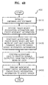
- FIG. 6A is a detailed block diagram of the application 170 of FIG. 1A
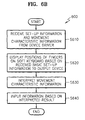
- FIG. 6B is a flowchart of operations in the application 170 of FIG. 6A for initializing configuration of the 3D input device, according to the present invention.
- FIGS. 6A and 6B configuration and operation of the application 170 will be described.
- the application 170 of FIG. 6A includes a soft keyboard displaying unit 171, which receives the movement characteristic information and the set-up information from the device driver 160, and displays the soft keyboard on an output device 180; a movement characteristic information interpreting unit 172, which interprets the received movement characteristic information; an information input unit 173, which inputs information based on the interpreted movement characteristic information; and a user setting unit 174 which allows a user to reconfigure the 3D input device of FIG. 1A .
- the soft keyboard displaying unit 171 receives the movement characteristic information and the set-up information from the device driver 160 (step S610).
- step S620 the soft keyboard displaying unit 171 displays finger positions on a soft keyboard displaying finger positions based on the received set-up information and transmits the soft keyboard to the output device 180 (step S620).
- FIG. 8 shows an example of the soft keyboard displayed on the output device 180. As shown in FIG. 8 , an adopted language is English and the input scenario is a cellular phone-type. It is also known that three sensors are connected.
- the movement characteristic information interpreting unit 172 interprets the received movement characteristic information in step S630. As described previously, the movement characteristic information includes the calculation results of the selection information and the determination results of whether there is any input operation. The movement characteristic interpreting unit 172 interprets the calculation results and determines the keys which correspond to the selected information. In addition, the movement characteristic interpreting unit 172 interprets the determination results of whether there is any input operation and decides whether to process the determination results as an information input.
- the information input unit 173 accepts information corresponding to the interpreted results of the movement characteristic information interpreting unit 172 in step S640.
- FIG. 7 is a flowchart 700 of operations in the application 170 of FIG. 6A for reconfiguration of the 3D input device of FIG. 1A , according to the present invention.
- Reconfiguration of the 3D information input device can be performed by the user setting unit 174 of the application 170.
- the application 170 receives a user request for manual setting of the 3D input device 110.
- the manual setting can be performed by the user using the user interface shown in FIG. 9 .
- the user interface may be included in a control board 900 provided by Microsoft Windows in a form of keyboard registration information 910 as general keyboard registration information.
- the user requests a setting change permission or cancel of use on a specific sensor (step S720), selects an input scenario in step S730, or selecting a user language in a manual setting menu (step S740).
- the user interface allows the user to select keyboard type, key arrays, fingers to use, and the user language.
- the application 170 When the application 170 receives such requests of changes, it transmits the set-up information to the device driver 160 (step S750), and then the device driver 160 reconfigures itself based on the received set-up information (step S760).
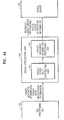
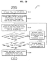
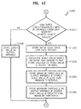
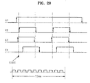
- FIG. 10 is a schematic flowchart 1000 of operations in the pre-processing unit 130 of FIG. 1A .
- the pre-processing unit 130 initializes a system (step S1010) and acquires sensor signals from the finger device 110 (step S1020). The operations for receiving the sensor signals will be described in detail with reference to FIG. 11 .
- the pre-processing unit 130 calculates a duty ratio of the received signal (step S1030), and then recognizes whether a user is wearing the finger device based on the received sensor signals (step S1040). The operations for calculating the duty ratio and recognizing whether the user is wearing the finger device will be described in detail with reference to FIG. 12 .
- the pre-processing unit 130 transmits signal values having the calculated duty ratio and an identification factor in which the finger device recognition information is stored to the signal-processing unit 140 (step S1050).
- the operations for transmitting the signal values and the identification factor to the signal-processing unit 140 will be described in detail with reference to FIG. 13 .
- the number of ports may be as many as the number of the sensor signals.
- each point value may be used as each sensor signal which passes corresponding port through.
- the pre-processing unit 130 receives current port values outputted from sensors 111, 112, 113, and 114 of the finger device 110 (step S1110).
- the current port values are stored as previous port values after a predetermined amount of time.
- the pre-processing unit 130 determines whether there is any change between the current port values and the previous port values (step S1120).
- a change in a port value means that an edge is triggered in a signal which passes the corresponding port through.
- the pre-processing unit 130 stores the current port values and information on the ports having port value changes in port status variables (step S1130).
- the pre-processing unit 130 stores a timer value at a current time when the port status variables are written with the port values and port information in an event time variable (step S1140). Namely, the current timer value indicates a time when the edge is triggered.
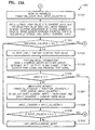
- FIG. 12 is a detail flowchart of steps 1030 and 1040 of FIG. 10 .
- the pre-processing unit 130 determines whether three edge-triggered-times can be obtained from each sensor.
- the edge-triggered-time is stored in the event time variable.
- the three event time variables are stored in time[0], time[1], and time[2].
- an error value is stored in an output variable (step S1240).
- the fact that the three edge-triggered-times cannot be extracted means that the edge is triggered less than three times for a predetermined time period. This indicates the sensor is not operating normally. Consequently, the error value is written to the output variable.
- the pre-processing unit 130 stores the initial edge state for each sensor (step S1220).
- step S1230 the pre-processing unit 130 calculates a scale value based on the event time variables and stores the calculated scale value to the output variable.
- step S1250 the pre-processing unit 130 stores a minimum threshold in the output variable if the stored scale value is less than the minimum threshold.
- step S1260 the pre-processing unit 130 stores a maximum threshold in the output variable if the stored scale value is greater than the maximum threshold.
- FIG. 13 is a detail flowchart of step 1050 of FIG. 10 .
- the pre-processing unit 130 checks the output variable having the error value, and stores the value in a no-signal variable.
- the no-signal variable includes information indicating a sensor is not normally outputting a sensor signal.
- step S1320 the pre-processing unit 130 transmits the output variable and the value included in the no-signal variable to the signal-processing unit 140.
- FIGS. 14 through 20 show a detailed algorithm used in the pre-processing unit 130 to recognize whether a user is wearing a finger device and to recognize the finger positions of the finger device.
- the pre-processing unit 130 initializes the system (step S1401) and proceeds to 'A' if an interrupt occurs in step S1402.
- the pre-processing unit 130 initializes variables (step S1501), more specifically, setting the values of Transition_Counter and Input_Counter to '0'.
- the pre-processing unit 130 inputs a current port value into Current_Input and a previous port value into Last_Input (step S1502).
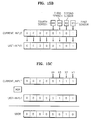
- the pre-processing unit 130 sequentially arranges values captured from N ports at urrent time and stores them in Current_Input.
- N refers to the number of sensors worn on the fingers or the number of click signals.
- N is 4.
- the pre-processing unit 130 stores 0000 0101 in Current_Input.
- the pre-processing unit 130 sets Last_Input to Current_Input and initializes a timer.
- the pre-processing unit 130 determines whether a value in Transition_Counter is less than the threshold value Ntc in step S1503.
- the threshold value Ntc may be 60, which indicates steps S1504 through S1510 are repeated 60 times. If Transition_Counter value is less than the threshold value Ntc, the pre-processing unit 130 proceeds to step S1504. Otherwise, the pre-processing unit 130 proceeds to B.
- step S1504 The pre-processing unit 130 captures current port values and stores the captured current port values in Current_Input.
- step S1505 the pre-processing unit 130 performs signal combination to determine whether there is any change between the current port values and the previous port values.
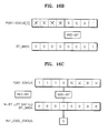
- the pre-processing unit 130 stores the results of an XOR operations of Last_Input, values and Current_Input values. In a variable of VXOR as shown in FIG. 15C .
- step S1506 the pre-processing unit 130 determines whether the VXOR value is '0' in step S1506.
- step S1510 sets Last_Input to Current_Input and proceeds to step S1503.
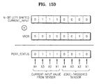
- the pre-processing unit 130 manipulates its variables by increasing the Transition_Counter value by 1, adding the VXOR value to a value of N-bit left shifted Current_Input value, and storing the added result in Port_Status [Input_Counter] (step S1507).
- the Current_Input value of 0000 0111 is 4-bit left shifted to the result 0111 0000. If 0000 0010 of the VXOR value is added to the left shifted Current_Input value, 0111 0010 is stored in Port_Status [Input_Counter].
- the first four bits of the 8-bit Port_Status indicate current sensor values, and the remaining four bits indicate an edge-triggered.
- the Port_Status value indicates the current sensor values of [X1 X2 X3 X4] are [1110], and the edge-triggered-sensor is X2.
- step S1507 the pre-processing unit 130 stores a current timer value in Event_Time[Input_Counter] in step S1507.
- step S1508 the pre-processing unit 130 increases Input_Counter by 1.
- step S1509 the pre-processing unit 130 determines whether the Input_Counter value is greater than a threshold value Nic.
- the threshold Nic value may be set to 23.
- the pre-processing unit 130 proceeds to B. If the Input_Counter value is less than or equal to the threshold value Nic, the pre-processing unit 130 stores the Current_Input value in Last_Input in step S1510 and proceeds to step S1503.
- the data table of FIG. 15E is obtained, with the information: Input_Counter, Current_Input which stores the current port value; Last_Input which stores the previous port value; VXOR which indicates a change in the current port value or the previous port value; Transition_Counter; Port_Status which indicates the current port value and information on a change-stricken, namely an edge-triggered port; and Event_Time which represents the time when the edge is triggered.
- Input_Counter Current_Input which stores the current port value
- Last_Input which stores the previous port value
- VXOR which indicates a change in the current port value or the previous port value
- Transition_Counter Port_Status which indicates the current port value and information on a change-stricken, namely an edge-triggered port
- Event_Time which represents the time when the edge is triggered.
- the current port value is 1010
- the change-stricken sensor is the third sensor
- the current timer value is 450.
- the operations after B include recognizing a sensor that does not operate normally based on the data of FIG. 15E and obtaining the predetermined number of the edge-triggered time, namely the timer values for a sensor that operates normally.
- step S1601 the pre-processing unit 130 sets Bit_Mask as 0000 0001 and count as '0'.
- step S1602 the pre-processing unit 130 determines whether the count value is less than N (step S1602). Step S1602 for determining whether the operations hereinafter are performed as many as the number of sensors worn on fingers.
- the pre-processing unit 130 proceeds to step S1603, otherwise, the pre-processing unit 130 proceeds to F.
- the pre-processing unit 130 sets Edge_Counter to '0' and Port_Status_Counter to '0'.
- step S1605 the pre-processing unit 130 determines whether the Port_Status_Counter value is less than a value of Input_Counter+1. If the Port_Status_Counter value is not less than the value of Input_Counter+1, the pre-processing unit 130 proceeds to 'D'. In step S1612, the Port_Status_Counter value is increased sequentially by 1. Input_Counter may store a value of 23. That the Port_Status_Counter value is not less than the value of Input_Counter+1 means an Edge_Counter alue is possibly smaller than 2 (step S1611).
- step S1612 only the Port_Status_Counter value gets increased by 1 (step S1612), which results excess of the Input_Counter value. That is, no more than two edges have been triggered in a sensor signal outputted from a sensor for a predetermined amount of time, indicating the sensor does not operate normally. Therefore, the pre-processing unit 130 proceeds to 'D' and stores the error value in the output variable.
- the pre-processing unit 130 determines whether the result of an AND_bit operation of Port_Status[Port_Status_Counter] and Bit_Mask is '0' in step S1606.
- AND_bit denotes the bit-wise AND operation. Referring to FIG. 16B , an AND_bit operation of Port-Status[3] having 1110 0001 (with reference to the data table of FIG. 15E ) and Bit_Mask having 0000 0001 results in the value '1'. Since the result is not '0', the pre-processing unit proceeds to step S1607.
- the pre-processing unit 130 then proceeds to store an Event_Time[Port_Status_Counter] alue in Time[Edge_Counter] in step S1607 and determines whether the Edge_Counter value is '0' in step S1608.
- the pre-processing unit 130 Unless the Edge_Counter value is '0', the pre-processing unit 130 increases the Edge_Counter value by 1 in step S1610. If the Edge_Counter value is '0', in step S1609, the pre-processing unit 130 performs the AND_bit operation of Port_Status[Port_Status_Counter] and N-bit left shifted Bit_Mask, storing the AND_bit operation result in Init_Edge_Status. For example, as shown in FIG. 16C , the AND_bit operation of Port_Status having 1110 xxxx and N-bit left shifted Bit_Mask, 0001 0000 results out '0'. The pre-processing unit 130 stores '0' in Init_Edge_Status.
- step S1610 the pre-processing unit increases the Edge_Counter value by 1.
- step S1611 the pre-processing unit 130 determines whether the Edge_Counter value is greater than '2', a satisfactory value for calculating a duty ratio of the sensor signal.
- the pre-processing unit 130 proceeds to 'C'. If the Edge_Counter value is not greater than 2, the pre-processing unit 130 increases the Port_Status_Counter value by 1 in step S1612 and proceeds to step S1605.
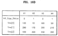
- Each sensor obtains values for Init_Edge_Status, Time[0], Time[1], and Time[2]. For example, in a case of the first sensor X1, as shown in FIG. 15E , when a port value for the first sensor X1 is '1' corresponding Transition_Counter values are '3', '7', and '11', and corresponding Event_Time values are 130, 280, and 430. In FIG.
- FIG. 16D shows information when all sensors X1, X2, X3, and X4 operate normally.
- the pre-processing unit 130 determines whether the Init_Edge_Status value is '0' (step S1701). Reflecting the determination result, a duty ratio for the sensor signal is calculated. If the Init_Edge_Status value is not '0', the pre-processing unit 130 stores Scale_Factor * (Time[1]-Time[0])/(Time[2]-Time[0]) in an output variable Output[count] (step S1702).
- Scale_Factor is for signal transmission. For example, if a calculated output value is to be transmitted in an 8-bit signal, the output variable value may be in a range of 0 - 225. Thus, for example, the Scale_Factor value may be 225.
- the pre-processing unit 130 determines whether the value of the output variable Output[count] is less than Min_Value, e.g., '1', in step S1704. If so, the pre-processing unit 130 stores Min_Value in the output variable Output[count] (step S1705) and proceeds to step S1709.
- the pre-processing unit 130 determines whether the output variable Output[count] value is greater than Max_Value, e.g., '255' (step S1706). If so, the pre-processing unit 130 stores Value_Something_Wrong in the output variable Output[count] (step S1707), and proceeds to step S1709.
- the pre-processing unit 130 stores Value_Something_Wrong in the output variable Output[count] in step 1708, and proceeds to step S1709. Since the output variable value stored according to the duty ratio calculation may have from Min_Value of '1' o Max_Value of '225', Value_Something_Wrong may be '0', which is not used as the output variable alue.
- step S1709 the pre-processing unit 130 shifts Bit_Mask to left direction by 1 bit and stores the result in Bit_Mask.
- the pre-processing unit 130 increases count by 1 in step S1710, and proceeds to 'E'.
- step S1801 the pre-processing unit 130 sets the Bit_Mask value to 0000 0001, count value to 0, and No_Exit_Signals value to 0000 0000.
- step S1802 the pre-processing unit 130 determines whether the count value is less than N.
- the count value greater than or equal to N means all operations in the pre-processing unit 130 have been completed. In this case, the pre-processing unit 130 proceeds to step S1807.
- the pre-processing unit 130 determines whether Output[count] has Value_Something_Wrong in step S1803.
- the pre-processing unit 130 proceeds to step S1805 and increases the count value by 1.
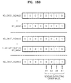
- the pre-processing unit 130 stores the summation result of a value of No_Exist_Signals (variable indicating the number of existing signals) and the Bit_Mask value in No_Exist_Signals in step S1804. For example, as shown in FIG. 18B , if Bit_Mask having 0000 0001 is added to No_Exist_Signals having 0000 0000, the summation result, 0000 0001, is stored in No_Exist_Signals. No_Exist_Signals having 0000 0001 indicates that the first sensor X1 is not operating normally or is not being worn by the user.
- step S1806 the pre-processing unit 130 shifts Bit_Mask to left direction by 1 bit, stores the result in Bit_Mask, and proceeds to step S1802.
- the pre-processing unit 130 recognize the sensors being worn by the user and those not being worn by the user.
Landscapes
- Engineering & Computer Science (AREA)
- General Engineering & Computer Science (AREA)
- Theoretical Computer Science (AREA)
- Human Computer Interaction (AREA)
- Physics & Mathematics (AREA)
- General Physics & Mathematics (AREA)
- User Interface Of Digital Computer (AREA)
- Position Input By Displaying (AREA)
Claims (10)
- Verfahren zum Konfigurieren einer dreidimensionalen, 3D, Informations-Eingabevorrichtung (100), welche Informations-Eingabevorgänge ausführt unter Verwendung einer Fingervorrichtung (110), die eine Vielzahl von Sensoren (X1, X2, X3, X4) umfasst, die von einem Nutzer getragen werden, und die Fingerbewegung des Nutzers abtastet, das Verfahren charakterisiert durch Umfassen der Schritte:Erkennen jener Sensoren (X1, X2, X3, X4), die von dem Nutzer getragen werden, und jener, die nicht von dem Nutzer getragen werden, und Erkennen von Fingerpositionen der Fingervorrichtung (110); undadaptives Konfigurieren der 3D-Eingabevorrichtung (100) basierend auf den Erkennungsresultaten.
- Verfahren gemäß Anspruch 1, wobei adaptives Konfigurieren der 3D-Eingabevorrichtung (100) umfasst:adaptives Konfigurieren einer Signalverarbeitungseinheit (140), die Bewegungssignale verarbeitet, die von der Fingervorrichtung (110) abgetastet werden, basierend auf den Erkennungsresultaten; undadaptives Konfigurieren eines Gerätetreibers (160) der 3D-Eingabevorrichtung (100), basierend auf den Erkennungsresultaten und grundlegender Einrichtungsinformation, die zur Informationseingabe verwendet wird.
- Verfahren gemäß Anspruch 2, wobei die grundlegende Einrichtungsinformation Eingabeszenarieninformation bezogen auf eine Anordnung von Informationselementen, die mittels Fingerbewegung ausgewählt werden, und eine Sprache, die zur Informationseingabe verwendet wird, umfasst.
- Verfahren gemäß Anspruch 2, wobei eine Anwendung (170) eine Softtastatur basierend auf den Erkennungsresultaten und der grundlegenden Einrichtungsinformation konfiguriert, wenn die Anwendung (170) die Erkennungsresultate und die grundlegenden Einrichtungsinformation vom Gerätetreiber (160) empfängt.
- Verfahren gemäß Anspruch 4, wobei die Anwendung (170) die konfigurierte Softtastatur an eine Ausgabevorrichtung (180) ausgibt.
- Verfahren gemäß Anspruch 5, wobei die Softtastatur Fingerpositionen der Fingervorrichtung (110) auf einem Feld von Informationselementen anzeigt, die durch Fingerbewegung ausgewählt werden.
- Dreidimensionale, 3D-, Eingabevorrichtung (100), die adaptiv konfigurierbar ist und Informations-Eingabevorgänge ausführt unter Verwendung einer Fingervorrichtung (110) umfassend eine Vielzahl von Sensoren (X1, X2, X3, X4), die von einem Nutzer getragen werden, und die Fingerbewegung des Nutzers abtastet, die 3D-Eingabevorrichtung (100) charakterisiert durch Umfassen von:einer Vorverarbeitungseinheit (130), welche jene Sensoren (X1, X2, X3, X4) erkennt, die vom Nutzer getragen werden und jene, die nicht vom Nutzer getragen werden, und die Fingerpositionen der Fingervorrichtung (110) erkennt; undeiner Signalverarbeitungseinheit (140), die adaptiv konfiguriert ist, Bewegungssignale zu verarbeiten, die von den Sensoren (X1, X2, X3, X4) der Fingervorrichtung (110), die vom Nutzer getragen wird, ausgegeben werden, basierend auf den Erkennungsresultaten aus der Vorverarbeitungseinheit (130).
- 3D-Eingabevorrichtung (100) gemäß Anspruch 7 weiter umfassend einen Gerätetreiber (160), der adaptiv konfigurierbar ist, die Bewegungssignale, die von der Signalverarbeitungseinheit (140) ausgegeben werden, zu verarbeiten, basierend auf den Erkennungsresultaten der Vorverarbeitungseinheit (130) und grundlegenden Einrichtungsinformation zur Informationseingabe.
- 3D-Eingabevorrichtung (100) gemäß Anspruch 8, wobei die grundlegenden Einrichtungsinformation eine Sprache, die zur Informationseingabe verwendet wird, und Eingabeszenarieninformation bezogen auf eine Anordnung von Informationselementen umfasst, die durch die Fingerbewegung ausgewählt werden, umfasst.
- 3D-Eingabevorrichtung (100) gemäß Anspruch 9 weiter umfassend eine Anwendung (170), die eine Softtastatur, die die Fingerpositionen der Fingervorrichtung (110) auf einer Anordnung von Informationselementen, die durch Fingerbewegung ausgewählt werden, basierend auf den Erkennungsresultaten und der grundlegenden Einrichtungsinformation, empfangen vom Gerätetreiber (160), konfiguriert.
Priority Applications (1)
| Application Number | Priority Date | Filing Date | Title |
|---|---|---|---|
| EP13174729.7A EP2648076B1 (de) | 2002-12-31 | 2003-12-26 | Verfahren zur erkennung des tragens einer 3d-eingabevorrichtung und gerät dafür |
Applications Claiming Priority (3)
| Application Number | Priority Date | Filing Date | Title |
|---|---|---|---|
| KR2002087939 | 2002-12-31 | ||
| KR10-2002-0087939A KR100537503B1 (ko) | 2002-12-31 | 2002-12-31 | 공간형정보입력장치 구성 방법, 재구성 방법, 착용인식방법 및그 장치 |
| PCT/KR2003/002850 WO2004059572A2 (en) | 2002-12-31 | 2003-12-26 | Method for configuring 3d input device, method for reconfiguring 3d input device, method for recognizing wearing of the 3d input device, and the apparatus thereof |
Related Child Applications (2)
| Application Number | Title | Priority Date | Filing Date |
|---|---|---|---|
| EP13174729.7A Division EP2648076B1 (de) | 2002-12-31 | 2003-12-26 | Verfahren zur erkennung des tragens einer 3d-eingabevorrichtung und gerät dafür |
| EP13174729.7A Division-Into EP2648076B1 (de) | 2002-12-31 | 2003-12-26 | Verfahren zur erkennung des tragens einer 3d-eingabevorrichtung und gerät dafür |
Publications (3)
| Publication Number | Publication Date |
|---|---|
| EP1579384A2 EP1579384A2 (de) | 2005-09-28 |
| EP1579384A4 EP1579384A4 (de) | 2011-02-09 |
| EP1579384B1 true EP1579384B1 (de) | 2014-10-22 |
Family
ID=36241082
Family Applications (2)
| Application Number | Title | Priority Date | Filing Date |
|---|---|---|---|
| EP03779023.5A Expired - Lifetime EP1579384B1 (de) | 2002-12-31 | 2003-12-26 | Konfigurationsverfahren für eine 3d-eingabevorrichtung, verfahren zur neukonfiguration einer 3d-eingabevorrichtung, verfahren zur erkennung des tragens der 3d-eingabevorrichtung und gerät dafür |
| EP13174729.7A Expired - Lifetime EP2648076B1 (de) | 2002-12-31 | 2003-12-26 | Verfahren zur erkennung des tragens einer 3d-eingabevorrichtung und gerät dafür |
Family Applications After (1)
| Application Number | Title | Priority Date | Filing Date |
|---|---|---|---|
| EP13174729.7A Expired - Lifetime EP2648076B1 (de) | 2002-12-31 | 2003-12-26 | Verfahren zur erkennung des tragens einer 3d-eingabevorrichtung und gerät dafür |
Country Status (7)
| Country | Link |
|---|---|
| US (1) | US8022925B2 (de) |
| EP (2) | EP1579384B1 (de) |
| JP (1) | JP4638242B2 (de) |
| KR (1) | KR100537503B1 (de) |
| CN (2) | CN100478856C (de) |
| AU (1) | AU2003285807A1 (de) |
| WO (1) | WO2004059572A2 (de) |
Families Citing this family (47)
| Publication number | Priority date | Publication date | Assignee | Title |
|---|---|---|---|---|
| KR100674090B1 (ko) * | 2004-12-20 | 2007-01-24 | 한국전자통신연구원 | 착용형 범용 3차원 입력 시스템 |
| JP4973449B2 (ja) * | 2007-10-30 | 2012-07-11 | セイコーエプソン株式会社 | 処理実行方法、そのプログラム及び処理実行装置 |
| US8358269B2 (en) * | 2008-07-18 | 2013-01-22 | Intel Corporation | Human interface device (HID) |
| JP4775459B2 (ja) * | 2009-02-27 | 2011-09-21 | 株式会社デンソー | 電子機器及び情報処理システム |
| US8581856B2 (en) * | 2009-05-27 | 2013-11-12 | Microsoft Corporation | Touch sensitive display apparatus using sensor input |
| KR101242416B1 (ko) * | 2009-12-21 | 2013-03-18 | 한국전자통신연구원 | 손가락에 연결된 줄의 장력 변화를 이용한 휴대형 문자 입력 장치 및 방법 |
| US20110260963A1 (en) * | 2010-04-27 | 2011-10-27 | Gm Global Technology Operations, Inc. | Symbolic input via mid-air finger/thumb motions |
| KR20120036244A (ko) * | 2010-10-07 | 2012-04-17 | 삼성전자주식회사 | 생체 이식 의료장치 및 그 제어방법 |
| US8490877B2 (en) | 2010-11-09 | 2013-07-23 | Metrologic Instruments, Inc. | Digital-imaging based code symbol reading system having finger-pointing triggered mode of operation |
| US9824091B2 (en) | 2010-12-03 | 2017-11-21 | Microsoft Technology Licensing, Llc | File system backup using change journal |
| US10275046B2 (en) | 2010-12-10 | 2019-04-30 | Microsoft Technology Licensing, Llc | Accessing and interacting with information |
| US8620894B2 (en) | 2010-12-21 | 2013-12-31 | Microsoft Corporation | Searching files |
| US8665210B2 (en) | 2010-12-22 | 2014-03-04 | Microsoft Corporation | Sensing user input using the body as an antenna |
| US9335793B2 (en) * | 2011-01-31 | 2016-05-10 | Apple Inc. | Cover attachment with flexible display |
| TW201310284A (zh) * | 2011-08-22 | 2013-03-01 | Wistron Corp | 滑鼠及判斷游標作動之方法 |
| TW201325101A (zh) * | 2011-12-13 | 2013-06-16 | Askey Technology Jiangsu Ltd | 遠端多點遙控裝置及系統 |
| CA3051912C (en) | 2012-02-24 | 2023-03-07 | Thomas J. Moscarillo | Gesture recognition devices and methods |
| FR3006477B1 (fr) * | 2013-05-29 | 2016-09-30 | Blinksight | Dispositif et procede de detection de la manipulation d'au moins un objet |
| KR102223376B1 (ko) * | 2014-03-14 | 2021-03-05 | 삼성전자주식회사 | 데이터 소스 결정 방법 |
| US20150302840A1 (en) * | 2014-04-18 | 2015-10-22 | Adam Button | Wearable device system for generating audio |
| DE102014106960A1 (de) * | 2014-05-16 | 2015-11-19 | Faindu Gmbh | Verfahren zur Darstellung einer virtuellen Interaktion auf zumindest einem Bildschirm und Eingabevorrichtung, System und Verfahren für eine virtuelle Anwendung mittels einer Recheneinheit |
| KR101649127B1 (ko) * | 2014-08-20 | 2016-09-02 | 박민희 | 지오메트리 글러브 및 핸드 프레임, 그리고 이를 이용한 측정 방법 |
| USD725130S1 (en) * | 2014-08-29 | 2015-03-24 | Nike, Inc. | Display screen with emoticon |
| USD726199S1 (en) | 2014-08-29 | 2015-04-07 | Nike, Inc. | Display screen with emoticon |
| USD723577S1 (en) * | 2014-08-29 | 2015-03-03 | Nike, Inc. | Display screen with emoticon |
| USD725129S1 (en) * | 2014-08-29 | 2015-03-24 | Nike, Inc. | Display screen with emoticon |
| USD723046S1 (en) * | 2014-08-29 | 2015-02-24 | Nike, Inc. | Display screen with emoticon |
| USD723578S1 (en) * | 2014-08-29 | 2015-03-03 | Nike, Inc. | Display screen with emoticon |
| USD725131S1 (en) * | 2014-08-29 | 2015-03-24 | Nike, Inc. | Display screen with emoticon |
| USD724098S1 (en) | 2014-08-29 | 2015-03-10 | Nike, Inc. | Display screen with emoticon |
| USD724099S1 (en) * | 2014-08-29 | 2015-03-10 | Nike, Inc. | Display screen with emoticon |
| USD723579S1 (en) * | 2014-08-29 | 2015-03-03 | Nike, Inc. | Display screen with emoticon |
| USD724606S1 (en) * | 2014-08-29 | 2015-03-17 | Nike, Inc. | Display screen with emoticon |
| KR101578345B1 (ko) * | 2014-09-03 | 2015-12-17 | 재단법인 실감교류인체감응솔루션연구단 | 역감을 재생하는 장치 |
| US9092684B1 (en) | 2015-01-08 | 2015-07-28 | Symbol Technologies, Llc | Wearable system for, and method of, electro-optically reading a symbol at which a user's finger is generally pointed |
| US9652038B2 (en) * | 2015-02-20 | 2017-05-16 | Sony Interactive Entertainment Inc. | Magnetic tracking of glove fingertips |
| CN106155272A (zh) * | 2015-03-25 | 2016-11-23 | 联想(北京)有限公司 | 输入设备、信息处理方法及装置 |
| KR102415906B1 (ko) | 2015-04-14 | 2022-07-01 | 엘지이노텍 주식회사 | 인체 착용 장치 및 이의 동작 방법 |
| US11983138B2 (en) | 2015-07-26 | 2024-05-14 | Samsung Electronics Co., Ltd. | Self-configuring SSD multi-protocol support in host-less environment |
| US10210123B2 (en) | 2016-07-26 | 2019-02-19 | Samsung Electronics Co., Ltd. | System and method for supporting multi-path and/or multi-mode NMVe over fabrics devices |
| US10346041B2 (en) | 2016-09-14 | 2019-07-09 | Samsung Electronics Co., Ltd. | Method for using BMC as proxy NVMeoF discovery controller to provide NVM subsystems to host |
| US11461258B2 (en) * | 2016-09-14 | 2022-10-04 | Samsung Electronics Co., Ltd. | Self-configuring baseboard management controller (BMC) |
| KR101853706B1 (ko) * | 2016-11-30 | 2018-05-02 | (주)슈팅스 | 손가락 마디 간 착용형 반지 타입의 사용자 조작 센싱 장치 |
| CN108196696B (zh) * | 2018-01-02 | 2022-02-22 | 京东方科技集团股份有限公司 | 一种可穿戴输入装置、主机、输入方法及电子系统 |
| KR102046706B1 (ko) * | 2018-02-27 | 2019-11-19 | 세종대학교산학협력단 | 착용가능 디바이스를 사용하여 신경망 기반의 제스처 인식을 수행하는 기법 |
| US20200249767A1 (en) * | 2019-02-01 | 2020-08-06 | Justin King | Virtual Keyboard Input Method |
| US11630556B2 (en) * | 2020-09-16 | 2023-04-18 | Kyndryl, Inc. | Finger control of wearable devices |
Family Cites Families (26)
| Publication number | Priority date | Publication date | Assignee | Title |
|---|---|---|---|---|
| US4414537A (en) * | 1981-09-15 | 1983-11-08 | Bell Telephone Laboratories, Incorporated | Digital data entry glove interface device |
| US4988981B1 (en) * | 1987-03-17 | 1999-05-18 | Vpl Newco Inc | Computer data entry and manipulation apparatus and method |
| US5097252A (en) | 1987-03-24 | 1992-03-17 | Vpl Research Inc. | Motion sensor which produces an asymmetrical signal in response to symmetrical movement |
| JPH0713690A (ja) | 1993-06-24 | 1995-01-17 | Casio Comput Co Ltd | データ処理装置 |
| JP2698320B2 (ja) * | 1993-08-31 | 1998-01-19 | 日本電信電話株式会社 | 常装着型入力システム、常装着型意図伝達システム、常装着型音楽用キーボードシステム及び常装着型点字入出力システム |
| US5638092A (en) * | 1994-12-20 | 1997-06-10 | Eng; Tommy K. | Cursor control system |
| JPH08272520A (ja) * | 1995-03-29 | 1996-10-18 | Asako Hanno | 手袋命令発信装置 |
| EP0864145A4 (de) * | 1995-11-30 | 1998-12-16 | Virtual Technologies Inc | Taktile rückkopplung für mensch-/maschinenschnittstelle |
| US6128004A (en) | 1996-03-29 | 2000-10-03 | Fakespace, Inc. | Virtual reality glove system with fabric conductors |
| KR19980036077U (ko) | 1996-12-13 | 1998-09-15 | 김영귀 | 자동차의 퓨즈박스 |
| KR19980036079U (ko) | 1996-12-13 | 1998-09-15 | 김영귀 | 트렁크리드의 엠블렘구조 |
| US6600480B2 (en) * | 1998-12-31 | 2003-07-29 | Anthony James Francis Natoli | Virtual reality keyboard system and method |
| US6075517A (en) * | 1998-05-10 | 2000-06-13 | Phoenix Technologies Ltd. | System and method for synchronization of pointing devices with different data packet sizes |
| US6407679B1 (en) * | 1998-07-31 | 2002-06-18 | The Research Foundation Of The State University Of New York | System and method for entering text in a virtual environment |
| JP2000132305A (ja) * | 1998-10-23 | 2000-05-12 | Olympus Optical Co Ltd | 操作入力装置 |
| WO2000038571A1 (en) * | 1998-12-31 | 2000-07-06 | Ball Semiconductor, Inc. | Position sensing system |
| US6766036B1 (en) * | 1999-07-08 | 2004-07-20 | Timothy R. Pryor | Camera based man machine interfaces |
| US6512838B1 (en) * | 1999-09-22 | 2003-01-28 | Canesta, Inc. | Methods for enhancing performance and data acquired from three-dimensional image systems |
| JP2001125728A (ja) | 1999-10-28 | 2001-05-11 | Olympus Optical Co Ltd | 操作入力装置 |
| JP2001236174A (ja) | 2000-02-25 | 2001-08-31 | Fujitsu Ltd | 手書き文字入力装置及び手書き文字認識方法 |
| US6744420B2 (en) * | 2000-06-01 | 2004-06-01 | Olympus Optical Co., Ltd. | Operation input apparatus using sensor attachable to operator's hand |
| TW507158B (en) * | 2001-01-05 | 2002-10-21 | Darfon Electronics Corp | Detecting device and method of mouse touch pad |
| JP4641354B2 (ja) * | 2001-03-05 | 2011-03-02 | 大日本印刷株式会社 | 着用型情報入力装置 |
| KR20020072367A (ko) | 2001-03-09 | 2002-09-14 | 삼성전자 주식회사 | 바이오 피드백을 이용한 정보 입력 시스템 및 정보 입력방법 |
| KR100446613B1 (ko) | 2001-07-16 | 2004-09-04 | 삼성전자주식회사 | 착용할 수 있는 정보 입력 장치를 사용한 정보 입력 방법 |
| US20030214481A1 (en) * | 2002-05-14 | 2003-11-20 | Yongming Xiong | Finger worn and operated input device and method of use |
-
2002
- 2002-12-31 KR KR10-2002-0087939A patent/KR100537503B1/ko not_active Expired - Fee Related
-
2003
- 2003-12-26 CN CNB2003801080592A patent/CN100478856C/zh not_active Expired - Fee Related
- 2003-12-26 WO PCT/KR2003/002850 patent/WO2004059572A2/en not_active Ceased
- 2003-12-26 EP EP03779023.5A patent/EP1579384B1/de not_active Expired - Lifetime
- 2003-12-26 AU AU2003285807A patent/AU2003285807A1/en not_active Abandoned
- 2003-12-26 EP EP13174729.7A patent/EP2648076B1/de not_active Expired - Lifetime
- 2003-12-26 US US10/540,925 patent/US8022925B2/en not_active Expired - Lifetime
- 2003-12-26 JP JP2004563017A patent/JP4638242B2/ja not_active Expired - Fee Related
- 2003-12-26 CN CNB2006101467327A patent/CN100421054C/zh not_active Expired - Fee Related
Also Published As
| Publication number | Publication date |
|---|---|
| CN1975636A (zh) | 2007-06-06 |
| EP1579384A4 (de) | 2011-02-09 |
| EP1579384A2 (de) | 2005-09-28 |
| CN100421054C (zh) | 2008-09-24 |
| KR20040061655A (ko) | 2004-07-07 |
| EP2648076B1 (de) | 2017-03-29 |
| WO2004059572A3 (en) | 2004-11-11 |
| EP2648076A1 (de) | 2013-10-09 |
| JP2006512645A (ja) | 2006-04-13 |
| CN1732429A (zh) | 2006-02-08 |
| KR100537503B1 (ko) | 2005-12-19 |
| US8022925B2 (en) | 2011-09-20 |
| WO2004059572A2 (en) | 2004-07-15 |
| AU2003285807A8 (en) | 2004-07-22 |
| AU2003285807A1 (en) | 2004-07-22 |
| CN100478856C (zh) | 2009-04-15 |
| JP4638242B2 (ja) | 2011-02-23 |
| US20060202950A1 (en) | 2006-09-14 |
Similar Documents
| Publication | Publication Date | Title |
|---|---|---|
| EP1579384B1 (de) | Konfigurationsverfahren für eine 3d-eingabevorrichtung, verfahren zur neukonfiguration einer 3d-eingabevorrichtung, verfahren zur erkennung des tragens der 3d-eingabevorrichtung und gerät dafür | |
| US5144594A (en) | Acoustic mouse system | |
| CN101165642B (zh) | 通用输入设备、操作方法及电路 | |
| US7978172B2 (en) | Switching device and switching methods of the same | |
| US20130069883A1 (en) | Portable information processing terminal | |
| US20050024321A1 (en) | Handheld remote instruction device for a computer-based visual presentation system | |
| WO2003010652A1 (en) | Method and apparatus for selecting information in multi-dimensional space | |
| EP1623296A2 (de) | Kontaktlose mensch-computer-schnittstelle | |
| CA2511293A1 (en) | Ambiguity resolution for predictive text entry | |
| US20080307119A1 (en) | Kvm switch for switching among computers by employing mouse movement signal and method thereof | |
| US20130157719A1 (en) | Mobile terminal and transmission processing method thereof | |
| JPH09134248A (ja) | ポインティング入力装置およびこの入力装置を備えた電子機器 | |
| US20190049558A1 (en) | Hand Gesture Recognition System and Method | |
| US7532200B2 (en) | Apparatus for setting multi-stage displacement resolution of a mouse | |
| KR102454640B1 (ko) | 적응형 uart 시리얼 인터페이스를 구비한 집적회로 | |
| US9377870B2 (en) | Device and method for inputting information | |
| CN115185377A (zh) | 交互模式切换方法及装置、设备、存储介质 | |
| US8432264B1 (en) | Motion-activated remote control backlight | |
| KR100509913B1 (ko) | 다중 형식 입력 장치 및 방법 | |
| JP5205360B2 (ja) | 入力情報決定装置、入力情報決定方法、入力情報決定プログラム及び入力情報決定プログラムを記録した記録媒体 | |
| US20220113833A1 (en) | Processing method and system for touch signals, and all-in-one touch machine | |
| JP7279342B2 (ja) | 実行装置、制御方法、及びプログラム | |
| US20090128490A1 (en) | Input apparatus and optical mouse for computer and operation method thereof | |
| US8570755B1 (en) | User configurable control panel layout for medical device | |
| JP4569250B2 (ja) | 入力装置、入力システムおよび入力方法 |
Legal Events
| Date | Code | Title | Description |
|---|---|---|---|
| PUAI | Public reference made under article 153(3) epc to a published international application that has entered the european phase |
Free format text: ORIGINAL CODE: 0009012 |
|
| 17P | Request for examination filed |
Effective date: 20050627 |
|
| AK | Designated contracting states |
Kind code of ref document: A2 Designated state(s): AT BE BG CH CY CZ DE DK EE ES FI FR GB GR HU IE IT LI LU MC NL PT RO SE SI SK TR |
|
| AX | Request for extension of the european patent |
Extension state: AL LT LV MK |
|
| RIC1 | Information provided on ipc code assigned before grant |
Ipc: 7G 06F 3/033 A |
|
| DAX | Request for extension of the european patent (deleted) | ||
| RBV | Designated contracting states (corrected) |
Designated state(s): DE FR |
|
| A4 | Supplementary search report drawn up and despatched |
Effective date: 20110111 |
|
| 17Q | First examination report despatched |
Effective date: 20110622 |
|
| RAP1 | Party data changed (applicant data changed or rights of an application transferred) |
Owner name: SAMSUNG ELECTRONICS CO., LTD. |
|
| REG | Reference to a national code |
Ref country code: DE Ref legal event code: R079 Ref document number: 60346909 Country of ref document: DE Free format text: PREVIOUS MAIN CLASS: G06F0003033000 Ipc: G06F0003010000 |
|
| RIC1 | Information provided on ipc code assigned before grant |
Ipc: G06F 3/023 20060101ALI20140430BHEP Ipc: G06F 3/01 20060101AFI20140430BHEP |
|
| GRAP | Despatch of communication of intention to grant a patent |
Free format text: ORIGINAL CODE: EPIDOSNIGR1 |
|
| INTG | Intention to grant announced |
Effective date: 20140616 |
|
| RIN1 | Information on inventor provided before grant (corrected) |
Inventor name: SOH, BYUNG-SEOK, 248-904 HWANGGOL MAEUL SSANGYONG, Inventor name: LEE, SANG-GOOG, 134-1504 GWANAK TOWN CHEONGGU APT. Inventor name: KIM, SUNG-CHEOL, C/O SAMSUNG ADVANCED INST OF TECH Inventor name: PARK, TAE-SIK, 224-803 3-JIGU DAERIM HANSUP APT. |
|
| GRAS | Grant fee paid |
Free format text: ORIGINAL CODE: EPIDOSNIGR3 |
|
| GRAA | (expected) grant |
Free format text: ORIGINAL CODE: 0009210 |
|
| AK | Designated contracting states |
Kind code of ref document: B1 Designated state(s): DE FR |
|
| REG | Reference to a national code |
Ref country code: DE Ref legal event code: R096 Ref document number: 60346909 Country of ref document: DE Effective date: 20141204 |
|
| REG | Reference to a national code |
Ref country code: DE Ref legal event code: R097 Ref document number: 60346909 Country of ref document: DE |
|
| PLBE | No opposition filed within time limit |
Free format text: ORIGINAL CODE: 0009261 |
|
| STAA | Information on the status of an ep patent application or granted ep patent |
Free format text: STATUS: NO OPPOSITION FILED WITHIN TIME LIMIT |
|
| 26N | No opposition filed |
Effective date: 20150723 |
|
| REG | Reference to a national code |
Ref country code: FR Ref legal event code: PLFP Year of fee payment: 13 |
|
| REG | Reference to a national code |
Ref country code: FR Ref legal event code: PLFP Year of fee payment: 14 |
|
| REG | Reference to a national code |
Ref country code: FR Ref legal event code: PLFP Year of fee payment: 15 |
|
| PGFP | Annual fee paid to national office [announced via postgrant information from national office to epo] |
Ref country code: DE Payment date: 20181205 Year of fee payment: 16 |
|
| PGFP | Annual fee paid to national office [announced via postgrant information from national office to epo] |
Ref country code: FR Payment date: 20181122 Year of fee payment: 16 |
|
| REG | Reference to a national code |
Ref country code: DE Ref legal event code: R119 Ref document number: 60346909 Country of ref document: DE |
|
| PG25 | Lapsed in a contracting state [announced via postgrant information from national office to epo] |
Ref country code: DE Free format text: LAPSE BECAUSE OF NON-PAYMENT OF DUE FEES Effective date: 20200701 Ref country code: FR Free format text: LAPSE BECAUSE OF NON-PAYMENT OF DUE FEES Effective date: 20191231 |