EP1578633B1 - Elektromechanisches stellglied für eine elektrisch betätigte feststellbremse - Google Patents
Elektromechanisches stellglied für eine elektrisch betätigte feststellbremse Download PDFInfo
- Publication number
- EP1578633B1 EP1578633B1 EP03786694A EP03786694A EP1578633B1 EP 1578633 B1 EP1578633 B1 EP 1578633B1 EP 03786694 A EP03786694 A EP 03786694A EP 03786694 A EP03786694 A EP 03786694A EP 1578633 B1 EP1578633 B1 EP 1578633B1
- Authority
- EP
- European Patent Office
- Prior art keywords
- actuator
- motor
- housing
- sub
- sub frame
- Prior art date
- Legal status (The legal status is an assumption and is not a legal conclusion. Google has not performed a legal analysis and makes no representation as to the accuracy of the status listed.)
- Revoked
Links
- 238000002955 isolation Methods 0.000 claims abstract description 35
- 238000013016 damping Methods 0.000 claims description 16
- 238000000034 method Methods 0.000 claims description 16
- 230000008878 coupling Effects 0.000 claims 3
- 238000010168 coupling process Methods 0.000 claims 3
- 238000005859 coupling reaction Methods 0.000 claims 3
- 239000000463 material Substances 0.000 description 19
- 238000010586 diagram Methods 0.000 description 8
- 230000008901 benefit Effects 0.000 description 6
- 230000000712 assembly Effects 0.000 description 4
- 238000000429 assembly Methods 0.000 description 4
- 230000005540 biological transmission Effects 0.000 description 4
- 239000011521 glass Substances 0.000 description 4
- 230000009467 reduction Effects 0.000 description 4
- 239000004677 Nylon Substances 0.000 description 3
- 230000013011 mating Effects 0.000 description 3
- 239000002184 metal Substances 0.000 description 3
- 229920001778 nylon Polymers 0.000 description 3
- -1 e.g. Substances 0.000 description 2
- 239000000843 powder Substances 0.000 description 2
- 230000004044 response Effects 0.000 description 2
- 230000000717 retained effect Effects 0.000 description 2
- 229910000831 Steel Inorganic materials 0.000 description 1
- 230000009471 action Effects 0.000 description 1
- 239000000969 carrier Substances 0.000 description 1
- 150000001875 compounds Chemical class 0.000 description 1
- 235000009508 confectionery Nutrition 0.000 description 1
- 230000003247 decreasing effect Effects 0.000 description 1
- 230000007812 deficiency Effects 0.000 description 1
- 239000011213 glass-filled polymer Substances 0.000 description 1
- 238000003780 insertion Methods 0.000 description 1
- 230000037431 insertion Effects 0.000 description 1
- 230000014759 maintenance of location Effects 0.000 description 1
- 230000007246 mechanism Effects 0.000 description 1
- 239000007769 metal material Substances 0.000 description 1
- 239000004033 plastic Substances 0.000 description 1
- 239000002861 polymer material Substances 0.000 description 1
- 230000008569 process Effects 0.000 description 1
- 238000005096 rolling process Methods 0.000 description 1
- 239000010959 steel Substances 0.000 description 1
- 230000001360 synchronised effect Effects 0.000 description 1
- 238000003466 welding Methods 0.000 description 1
Images


Classifications
-
- F—MECHANICAL ENGINEERING; LIGHTING; HEATING; WEAPONS; BLASTING
- F16—ENGINEERING ELEMENTS AND UNITS; GENERAL MEASURES FOR PRODUCING AND MAINTAINING EFFECTIVE FUNCTIONING OF MACHINES OR INSTALLATIONS; THERMAL INSULATION IN GENERAL
- F16D—COUPLINGS FOR TRANSMITTING ROTATION; CLUTCHES; BRAKES
- F16D65/00—Parts or details
- F16D65/14—Actuating mechanisms for brakes; Means for initiating operation at a predetermined position
- F16D65/16—Actuating mechanisms for brakes; Means for initiating operation at a predetermined position arranged in or on the brake
- F16D65/18—Actuating mechanisms for brakes; Means for initiating operation at a predetermined position arranged in or on the brake adapted for drawing members together, e.g. for disc brakes
-
- B—PERFORMING OPERATIONS; TRANSPORTING
- B60—VEHICLES IN GENERAL
- B60T—VEHICLE BRAKE CONTROL SYSTEMS OR PARTS THEREOF; BRAKE CONTROL SYSTEMS OR PARTS THEREOF, IN GENERAL; ARRANGEMENT OF BRAKING ELEMENTS ON VEHICLES IN GENERAL; PORTABLE DEVICES FOR PREVENTING UNWANTED MOVEMENT OF VEHICLES; VEHICLE MODIFICATIONS TO FACILITATE COOLING OF BRAKES
- B60T11/00—Transmitting braking action from initiating means to ultimate brake actuator without power assistance or drive or where such assistance or drive is irrelevant
- B60T11/04—Transmitting braking action from initiating means to ultimate brake actuator without power assistance or drive or where such assistance or drive is irrelevant transmitting mechanically
- B60T11/046—Using cables
-
- B—PERFORMING OPERATIONS; TRANSPORTING
- B60—VEHICLES IN GENERAL
- B60T—VEHICLE BRAKE CONTROL SYSTEMS OR PARTS THEREOF; BRAKE CONTROL SYSTEMS OR PARTS THEREOF, IN GENERAL; ARRANGEMENT OF BRAKING ELEMENTS ON VEHICLES IN GENERAL; PORTABLE DEVICES FOR PREVENTING UNWANTED MOVEMENT OF VEHICLES; VEHICLE MODIFICATIONS TO FACILITATE COOLING OF BRAKES
- B60T13/00—Transmitting braking action from initiating means to ultimate brake actuator with power assistance or drive; Brake systems incorporating such transmitting means, e.g. air-pressure brake systems
- B60T13/74—Transmitting braking action from initiating means to ultimate brake actuator with power assistance or drive; Brake systems incorporating such transmitting means, e.g. air-pressure brake systems with electrical assistance or drive
- B60T13/741—Transmitting braking action from initiating means to ultimate brake actuator with power assistance or drive; Brake systems incorporating such transmitting means, e.g. air-pressure brake systems with electrical assistance or drive acting on an ultimate actuator
-
- B—PERFORMING OPERATIONS; TRANSPORTING
- B60—VEHICLES IN GENERAL
- B60T—VEHICLE BRAKE CONTROL SYSTEMS OR PARTS THEREOF; BRAKE CONTROL SYSTEMS OR PARTS THEREOF, IN GENERAL; ARRANGEMENT OF BRAKING ELEMENTS ON VEHICLES IN GENERAL; PORTABLE DEVICES FOR PREVENTING UNWANTED MOVEMENT OF VEHICLES; VEHICLE MODIFICATIONS TO FACILITATE COOLING OF BRAKES
- B60T13/00—Transmitting braking action from initiating means to ultimate brake actuator with power assistance or drive; Brake systems incorporating such transmitting means, e.g. air-pressure brake systems
- B60T13/74—Transmitting braking action from initiating means to ultimate brake actuator with power assistance or drive; Brake systems incorporating such transmitting means, e.g. air-pressure brake systems with electrical assistance or drive
- B60T13/746—Transmitting braking action from initiating means to ultimate brake actuator with power assistance or drive; Brake systems incorporating such transmitting means, e.g. air-pressure brake systems with electrical assistance or drive and mechanical transmission of the braking action
-
- B—PERFORMING OPERATIONS; TRANSPORTING
- B60—VEHICLES IN GENERAL
- B60T—VEHICLE BRAKE CONTROL SYSTEMS OR PARTS THEREOF; BRAKE CONTROL SYSTEMS OR PARTS THEREOF, IN GENERAL; ARRANGEMENT OF BRAKING ELEMENTS ON VEHICLES IN GENERAL; PORTABLE DEVICES FOR PREVENTING UNWANTED MOVEMENT OF VEHICLES; VEHICLE MODIFICATIONS TO FACILITATE COOLING OF BRAKES
- B60T7/00—Brake-action initiating means
- B60T7/02—Brake-action initiating means for personal initiation
- B60T7/08—Brake-action initiating means for personal initiation hand actuated
- B60T7/10—Disposition of hand control
- B60T7/107—Disposition of hand control with electrical power assistance
-
- F—MECHANICAL ENGINEERING; LIGHTING; HEATING; WEAPONS; BLASTING
- F16—ENGINEERING ELEMENTS AND UNITS; GENERAL MEASURES FOR PRODUCING AND MAINTAINING EFFECTIVE FUNCTIONING OF MACHINES OR INSTALLATIONS; THERMAL INSULATION IN GENERAL
- F16D—COUPLINGS FOR TRANSMITTING ROTATION; CLUTCHES; BRAKES
- F16D65/00—Parts or details
- F16D65/0006—Noise or vibration control
-
- F—MECHANICAL ENGINEERING; LIGHTING; HEATING; WEAPONS; BLASTING
- F16—ENGINEERING ELEMENTS AND UNITS; GENERAL MEASURES FOR PRODUCING AND MAINTAINING EFFECTIVE FUNCTIONING OF MACHINES OR INSTALLATIONS; THERMAL INSULATION IN GENERAL
- F16D—COUPLINGS FOR TRANSMITTING ROTATION; CLUTCHES; BRAKES
- F16D2121/00—Type of actuator operation force
- F16D2121/18—Electric or magnetic
- F16D2121/24—Electric or magnetic using motors
-
- F—MECHANICAL ENGINEERING; LIGHTING; HEATING; WEAPONS; BLASTING
- F16—ENGINEERING ELEMENTS AND UNITS; GENERAL MEASURES FOR PRODUCING AND MAINTAINING EFFECTIVE FUNCTIONING OF MACHINES OR INSTALLATIONS; THERMAL INSULATION IN GENERAL
- F16D—COUPLINGS FOR TRANSMITTING ROTATION; CLUTCHES; BRAKES
- F16D2125/00—Components of actuators
- F16D2125/18—Mechanical mechanisms
- F16D2125/44—Mechanical mechanisms transmitting rotation
- F16D2125/46—Rotating members in mutual engagement
- F16D2125/48—Rotating members in mutual engagement with parallel stationary axes, e.g. spur gears
-
- F—MECHANICAL ENGINEERING; LIGHTING; HEATING; WEAPONS; BLASTING
- F16—ENGINEERING ELEMENTS AND UNITS; GENERAL MEASURES FOR PRODUCING AND MAINTAINING EFFECTIVE FUNCTIONING OF MACHINES OR INSTALLATIONS; THERMAL INSULATION IN GENERAL
- F16D—COUPLINGS FOR TRANSMITTING ROTATION; CLUTCHES; BRAKES
- F16D2125/00—Components of actuators
- F16D2125/18—Mechanical mechanisms
- F16D2125/44—Mechanical mechanisms transmitting rotation
- F16D2125/46—Rotating members in mutual engagement
- F16D2125/50—Rotating members in mutual engagement with parallel non-stationary axes, e.g. planetary gearing
-
- F—MECHANICAL ENGINEERING; LIGHTING; HEATING; WEAPONS; BLASTING
- F16—ENGINEERING ELEMENTS AND UNITS; GENERAL MEASURES FOR PRODUCING AND MAINTAINING EFFECTIVE FUNCTIONING OF MACHINES OR INSTALLATIONS; THERMAL INSULATION IN GENERAL
- F16D—COUPLINGS FOR TRANSMITTING ROTATION; CLUTCHES; BRAKES
- F16D2125/00—Components of actuators
- F16D2125/18—Mechanical mechanisms
- F16D2125/44—Mechanical mechanisms transmitting rotation
- F16D2125/46—Rotating members in mutual engagement
- F16D2125/52—Rotating members in mutual engagement with non-parallel stationary axes, e.g. worm or bevel gears
Definitions
- the present invention relates generally to electrically actuated parking brake systems for passenger vehicles, and, in particular, to an actuator assembly for controlling the parking brake function within passenger vehicles.
- Electric parking brake systems have been provided in vehicles to allow the application and release of the parking brake via electrical signal, eliminating the current mechanical connection, i.e. cable and lever.
- These systems typically include an electro-mechanical actuator connected to the brake caliper either by a cable, as in the drum in head, or directly attached to the brake caliper.
- the actuator converts electrical power to rotational mechanical output power for moving the cable or drive screw and applying the brakes.
- audible noise is a significant feature differentiating actuators in parking brake systems and many other actuation applications.
- a loud system is desirable to alert an operator that the actuator is being cycled.
- a quiet system is desirable to keep in-cabin noise to a minimum.
- An electromechanical actuator for an electrically actuated parking system is for instance known from WO 89/10496 .
- the electromechanical actuator according to WO 89/10496 comprises an actuator housing, a motor having a drive shaft and a gear train coupled to said drive shaft for driving an output of said actuator.
- the housing of the actuator defines a motor cavity which receives at least a portion of said motor.
- the caliper housing of the electromechanical actuator according to WO 89/10496 includes an end portion which is integral with the remaining portions of the caliper housing so that the planetary gear assemblies and pistons are both enclosed within the bores of the housing.
- the gear assemblies are small enough to be housed within bores and provide the required actuation loads while permitting the utilization of an integral caliper housing which is disposed about the ends of the gear assemblies in order to receive the reaction loading or forces effected by the gear assemblies when they operate.
- a break caliper with internal motor is also disclosed in EP 1 321 691 .
- This brake caliper comprises a motor having a shaft, at least one first planetary gear, and at least one second planetary gear.
- the first planetary gear is rotably engaged with the shaft and with a piston and is operatively engaged with a first carrier.
- the second planetary gear is operatively engaged with the first stage carrier and with the second carrier.
- the motor is fixably mounted within a bore in the caliper housing.
- the central mounting plate may be provided as a sub-frame. Accordingly, the central mounting plate may include an isolator having an effective spring constant and damping constant, wherein the isolator couples the mounting plate to an actuator housing.
- FIG. 1 is a simplified block diagram of an exemplary electronic parking brake actuator (EPBA) system 100 consistent with the present invention.
- the EPBA may include an actuator 102 that receives electrical power from a vehicle power source 104, e.g., a vehicle battery.
- the actuator may convert electrical energy to mechanical energy to drive a variety of devices.
- the actuator 102 may drive a brake caliper 106 associated, for example, with an emergency brake system.
- the actuator 102 may be coupled to a brake caliper 106 for applying the brakes.
- the actuator 102 may be coupled to the brake caliper 106 via a push-rod for actuating the brake.
- a cam mechanism may produce braking action at the brake caliper 106 in response to the rotational output of the actuator 102.
- the actuator 102 may be adapted to provide a linear output that may be coupled to the brake caliper 106.
- the actuator 102 may be mounted directly to a brake caliper 106.
- the actuator 102 may be mounted to any suitable portion of a vehicle, including frame, body, and trim components. It will be understood that depending upon the particular mounting location and techniques, i.e. hard mounted versus soft mounting through an elastic member, operation of the actuator may cause a variety of audible noises. As later detailed herein, an actuator consistent with the present invention may be configured for tailoring the audible noise of the actuator to a desired level.
- the emergency brake caliper 106 may thus be selectively engaged from, e.g., a vehicle cockpit by a vehicle driver.
- the emergency brake may be engaged by the manual operation of a switch, in a similar manner as the manual engagement of a hand brake or pedal operated emergency brake.
- the system 100 of the present invention may also be engaged in response to inputs from various sensors.
- a sensor may be provided on an automatic transmission to engage the emergency brake when the "park" position is selected.
- a sensor may be provided to detect motion of the vehicle when the engine is turned off.
- the emergency brake system may be configured to actuate the brake caliper 106 if rolling motion of the vehicle is detected while the engine is turned off.
- FIG. 2 a simplified block diagram of the internal components of an actuator 102 consistent with the present invention is illustrated.
- These components include a motor 200 (or a plurality of motors) for converting electrical energy from the power source to mechanical energy.
- the output shaft of the motor 200 may be coupled to a drive gear 202, e.g., a pinion gear, a worm gear, or the like.
- the drive gear 202 may be coupled to a driven gear 204, e.g., a spur gear, a worm wheel, or the like.
- the driven gear 204 may be in meshing engagement with a single or multiple stage planetary gear set 206.
- the output shaft 208 may then provide one mechanical output through an associated output port.
- the gear train may have an overall efficiency in the range of 60% and greater. However, lower efficiency gear trains may also be suitable for various applications.
- the drive gear 202 may be coupled to the driven gear 204 via a drive belt 203, for example a toothed drive belt such as a synchronous timing belt.
- the drive gear 202 may be a drive pulley
- the driven gear 204 may be a driven pulley.
- the driven pulley 204 may be in meshing engagement with the single or multiple stage planetary gear set 206.
- the output shaft 208 may then provide one mechanical output through the associated output port.
- the drive gear 202 may alternatively be in meshing engagement with the driven gear 204.
- An electrical energy source (not shown), e.g. the vehicle battery, may be connected to the actuator 102 along with other control inputs, via connector pins in an integral connector assembly, which may be formed on a cover portion of the actuator housing.
- the connector pins may provide electrical confections to a PCB, which may include motor control and position sensing electronics for driving the motor.
- a bottom portion of the housing may include integral locating features for the actuator components as well as mechanical attachment points for securing the actuator to a fixed location.
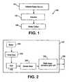
- FIG. 4 is a top-end view of the actuator 102.
- the actuator 102 may include an actuator housing 301 having a top cover 305, shown removed in FIG. 4 . With the housing top portion, or cover, 305 removed, a drive pulley 302 may be seen coupled to a driven pulley 304 via a drive belt 303.
- the motor and planetary gear set may be contained in housing 301.
- an output 308 of the actuator 102 may be provided extending from the bottom-end of the actuator housing 301 adjacent the motor. Those having skill in the art will appreciate that the output 308 may be provided at other locations on the housing 301 by utilizing different gear arrangements that will be readily understood.
- the illustrated exemplary embodiment 102 provides an actuator output in a compact configuration useful in the limited space available in automotive applications, such as in an electrically actuated parking brake.
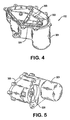
- the actuator 102 may include a motor 300 mounted to a sub-frame 312, e.g. a mid plate.
- the motor shaft may carry a drive pulley 302, disposed on the opposed side of the sub-frame 312 that drives a driven pulley 304 via a drive belt 303.
- the driven pulley 304 in turn drives a double planetary gear set 306.
- the driven pulley 304 may drive the planetary gear set 306 via a shaft extending through the sub-frame 312 and coupled to the a gear in meshing engagement with the planetary gear set 306.
- the driven pulley 304 may be configured as a compound gear. That is, the driven pulley 304 may include a pulley portion engaged with the drive belt 303 and a geared portion that extends through the sub-frame and is in meshing engagement with the planetary gear set 306.
- the motor 300 and drive train of the actuator 102 may be mounted on the sub-frame 312. This configuration may facilitate assembly of the actuator 102. By mounting the components to the sub-frame 312 outside of the actuator housing 301 much greater access is provided to the components and ease of handling is improved. Furthermore, once the components have been mounted to the sub-frame 312, as shown in FIG. 6 , performance of the actuator 102 may be tested prior to final assembly. Accordingly, detected problems may be resolved at an earlier stage in the assembly process.
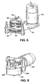
- the actuator 102 may include a housing top portion 305 that may be positioned on the actuator housing 301, thereby substantially enclosing the actuator.
- the top portion 305 may include a connector fitting 307 for receiving terminals 313 that are coupled to the motor 300, e.g. for providing power to the motor and/or control signals.
- the connector fitting 307 may be formed as a protruding feature, as illustrated.
- the top portion 305 may merely be formed having openings to accept wiring therethrough.
- the illustrated exemplary actuator 102 also includes a sub-frame top portion 314 that may be disposed on the sub-frame, or mid-plate, 312 and may cover at least a portion of the drive gear 302, driven gear 304 and drive belt 303.
- a sub-frame top portion 314 may be disposed on the sub-frame, or mid-plate, 312 and may cover at least a portion of the drive gear 302, driven gear 304 and drive belt 303.
- Various means of securing the sub-frame top portion 314 to the sub-frame 312 will be understood by those having skill in the art.
- the terminals 313 may be secured to the top portion of the sub-frame 314, thereby orienting the terminals 313 to be received in the connector fitting 307 as well as orienting the terminals 313 to be coupled to the motor 300. Additionally, mounting the terminals to the top portion 314 may allow the terminals to better resist push-pull forces. Consistent with this embodiment wherein the terminals are secured to the top portion of the sub-frame 314, it may be desirable to form the top portion 314 from a polymer material to effectively retain and insulate the terminals.
- the housing 301 and the top portion 305 may be formed from a polymeric material. Increased strength and durability may further be achieved by using a reinforced polymeric material, such as glass filled Nylon.
- the drive and driven pulley may be formed from a polymeric material, including a reinforced polymeric material such as glass filled Nylon.
- the planetary gear set including the planet gears, carriers, and the ring gear may also be formed from a variety of different materials, including both polymeric materials and metallic materials.
- the planetary gear assembly may be formed from powder metal, thereby providing strong components. Gear sets formed from powder metal may be further strengthened by heat treating.
- Audible noise has become a significant attribute of electro-mechanically actuated systems in passenger vehicles.
- One exemplary manner of reducing audible noise consistent with the invention is by gear train selection. Referring to FIG. 8 , by replacing the motor pinion drive gear and driven gear with a worm gear 202b and worm wheel 204b, as illustrated, a significant reduction in audible noise can be achieved.
- FIG. 9 is a block diagram illustrating motor isolation consistent with the invention.
- a motor 900 having a certain mass 902 and energy, i.e. generating motor inertia 904, may be coupled to an isolator, e.g., a pair of isolation bushings on either side of the motor.
- the isolator has an effective spring constant 906 and damping constant 908, both of which may be varied depending on the type of material and geometry chosen for the isolator.
- the isolator thus mechanically isolates the motor from the mass of the actuator housing 910, thereby reducing air born audible noise associated with motor vibration.
- the illustrated exemplary embodiment includes a motor isolation assembly in an actuator 102 consistent with the present invention.
- first and second housing portions are configured to define a motor isolation cavity.
- a first portion of the cavity is defined by the main housing 301, and a cover to the cavity is provided by the sub-frame 312, which may cover the top of the isolation cavity when installed in the housing 301.
- the motor 300 may be disposed in the isolation cavity, which may be separate from the remainder of the actuator 102.
- a first isolation bushing 316 and a second isolation busing 318 may be provided at associated ends of the motor 300.
- the isolation bushings 316, 318 and the mating main housing 301 and sub-frame 312 portions may not only isolate the motor 300 in the motor cavity but also prevent the transmission of vibrations from the motor 300 to the remainder of actuator components, thereby reducing associated audible noise.
- the audible noise may be adjusted by selection of the isolation bushing material to provide appropriate spring and damping constants.
- FIG. 10 is a block diagram illustrating an exemplary sub-frame configuration consistent with the invention.
- a motor having a certain mass 1002 and energy i.e. providing motor inertia 1004 may be coupled to a motor isolator or isolators, e.g., pair of isolation bushing on either side of the motor.
- the motor isolator has an effective spring constant 1006 and damping constant 1008, both of which may be varied depending on the type of material and geometry chosen for the motor isolator.
- the motor is isolated from the mass of the sub-frame 1010.
- the mass of the sub-frame may be chosen to minimize transfer of vibration by adjusting the volume and material density.
- the sub-frame is coupled to the mass of the outer shell 1016 of an actuator consistent with the invention.
- the sub-frame isolator or isolators Similar to the motor isolator, the sub-frame isolator or isolators have an effective spring constant 1012 and damping constant 1014 isolating the sub-frame 1010 from the outer shell 1016 of the actuator.
- the effective spring constant 1012 and damping constant 1014 for the sub-frame isolator can be tailored by selection of an appropriate material and geometry for the isolator.
- the exemplary actuator 102 includes both a motor 300 and a sub-frame isolation assembly, which includes the sub-frame lower portion 312 and the sub-frame top portion 314. Mating of the sub-frame top portion 314 and lower 312 portions of the sub-frame may at least partially enclose the actuator drive gear 302, driven gear 304 and drive belt 303 components, as well as isolate the motor 300 in a separate isolation cavity defined by the housing 301 and the sub-frame 312.
- first and second isolation bushings 316, 318 may also reduce the transmission of vibrations from the motor 300.
- the bushings 316, 318 may be formed from materials chosen to provide desired spring and damping constants for reducing noise.
- the motor may also be retained to the sub-frame 312 by straps 320.
- the straps 320 may be formed from a material chosen to provide a desired spring constant and damping constant.
- the sub-frame may be constructed from a variety of materials to assist with audible noise reduction.
- the sub-frame top portion 314 may be a low-density material, e.g., a plastic
- the sub-frame lower portion 312 may be a higher density material, e.g., metal such as steel.
- the motor 300 may be contained in a motor isolation cavity defined by the main housing 301.
- the motor isolation cavity may be completed by the sub-frame 312 disposed over the opening of the isolation cavity defined by the housing 301.
- the planetary gear set 306 may also be contained in an isolation cavity defined by the main housing 301. Similar to the motor isolation scheme, the planetary gear set 306 may be isolated from the sub-frame 312 by a bushing 322.
- the planetary gear set isolation bushing 322 may be formed from a material chosen to provide a desired spring constant and damping constant.
- a main portion 301 and a top portion 305 of the actuator housing mate to enclose the sub-frame 312.
- the sub-frame top portion 314 is isolated from the actuator housing top portion 305 by an isolator 326.
- the sub-frame lower portion 312 is isolated from the main housing portion 301 of the actuator by a plurality of isolators.
- the isolators may include central openings for accepting associated protrusions on the sub-frame lower portion 312 which extend into corresponding openings in the main housing portion 301 of the actuator.
- the isolators or grommets may, for example, be elastomeric for achieving a desired spring and damping constant.
- the motor may thus be isolated from the sub-frame by bushings, and all actuator components, including the motor, may be isolated from the outer actuator housing by the sub-frame, which may be isolated from the outer actuator housing by isolators.
- the actuator housing when the actuator housing is affixed to another system, such as a brake caliper or vehicle body, the actuator components are mechanically isolated in the sub-frame. This provides a benefit to vehicle manufacturers as mechanical vibration transmission to the mating assembly is minimized. Also, adjustment of the spring and damping constants associated with the bushings and isolators, and adjustment of the sub-frame and actuator housing materials, allows for tuning of the audible noise associated with the actuator for a particular application.
- the sub-frame may include a housing that at least partially encloses or surrounds the motor as well as at least a portion of the gear train.
- the motor may be attached to the sub-frame in an isolated configuration. Such a configuration may eliminate the need to provide isolators or bushings between the motor and the housing.
- the motor may be contained by the sub-frame such that it is not necessary to additionally support the motor on the housing. This last aspect, however, may also be achieved be securely associating the motor with a mid-plate type sub-frame, herein the motor is completely supported on the sub-frame without the sub-frame at least partially enclosing the motor.
- An electronic parking brake actuator including isolation features consistent with the present invention may realize reduced audible noise as compared to an actuator not using isolation features.
- the audible noise of an actuator consistent with the present invention may be decreased to at least around 19.9 sones during application of the brake and 21.9 sones during the release of the brake, as compared to 30.5 sones and 27.4 sones for a conventional actuator. These observed sound levels were recorded by a microphone positioned 150 mm from the actuator and positioned at a right angle thereto.
- Controlling the audible noise may include reducing or eliminating the audible noise in the vehicle cabin.
- controlling the audible noise may include transmitting at least a portion of the audible noise from the actuator to the vehicle cabin.
- the bushings, isolators, and isolation cavity may be selected to pass a desired level or frequency to the vehicle cabin.
- controlling the audible noise from the actuator may include passing certain frequencies of sound, e.g. low frequency sound, to the cabin while eliminating other frequencies.
- an actuator may be manufactured by first greasing and assembling a ring gear of a planetary gear set. A bushing for the motor may then be pressed into the mid-plate and a washer associated with the planetary gear set may be pressed into the ring gear. Next, a motor may be assembled to the mid-plate using a retention strap. With the motor retained to the mid-plate, a drive pulley may be pressed onto the output shaft of the motor. A driven pulley and a drive belt may then be loaded onto the assembly, and the belt may be fully engaged with the drive pulley and the driven pulley.
- electrical terminals may be assembled to a top portion of the mid-plate, for example by ultrasonically welding the terminals to the top portion of the mid-plate.
- the top portion of the mid-plate may then be joined to the mid-plate and the ring gear and the isolators may be loaded onto the mid-plate and the top portion of the mid-plate.
- the terminals may then be spot welded to the motor.
- operation of the actuator may be tested by providing power to the motor.
- the actuator components may next be installed in the actuator housing.
- the main housing and housing top portion may be perimeter welded. If the main housing and/or the top portion of the housing are formed from glass filled plastic, e.g., glass filled nylon, weld quality may be improved by providing reduced glass content in the top portion of the housing.
Landscapes
- Engineering & Computer Science (AREA)
- Mechanical Engineering (AREA)
- Transportation (AREA)
- General Engineering & Computer Science (AREA)
- Braking Systems And Boosters (AREA)
- Braking Arrangements (AREA)
- Connection Of Motors, Electrical Generators, Mechanical Devices, And The Like (AREA)
Claims (13)
- Elektromechanisches Betätigungselement umfassend:ein Betätigungselementgehäuse (301),einen Motor (300) mit einer Antriebswelle,einen mit der Antriebswelle verbundenen Getriebezug zur Betätigung eines Abtriebs des Betätigungselements (102), wobei das Gehäuse (301) einen Motorraum ausbildet, der wenigstens einen Teil des Motors aufnimmt,dadurch gekennzeichnet, dass
das Betätigungselement (301) weiterhin einen Hilfsrahmen (312) umfasst, wobei der Motor (300) und wenigstens ein Teil des Getriebezugs an dem Hilfsrahmen (312) befestigt sind, wobei der Hilfsrahmen (312) so ausgebildet ist, dass der Motor (3) und der Getriebezug des Betätigungselements (102) außerhalb des Betätigungselementgehäuses (301) montiert werden können. - Elektromechanisches Betätigungselement nach Anspruch 1, dadurch gekennzeichnet, dass
der Getriebezug angetriebene Räder (204, 304) umfasst, welche mit einem Planetengetriebe (206, 306) verbunden sind und dass wenigstens eines der angetriebenen Räder (204, 304) und das Planentengetriebe (206, 306) an dem Hilfsrahmen (312) befestigt sind. - Elektromechanisches Betätigungselement nach Anspruch 2, dadurch gekennzeichnet, dass
das Betätigungselementgehäuse (301) einen Planetengetrieberaum ausbildet, welcher wenigstens einen Teil des Planetengetriebes (206, 306) aufnimmt und dass durch das Zusammenwirken zwischen dem Gehäuse (301) und dem Hilfsrahmen (312) das Planetengetriebe (206, 306) von dem Rest des Betätigungselements getrennt ist. - Elektromechanisches Betätigungselement nach Anspruch 2, dadurch gekennzeichnet, dass
das Betätigungselementgehäuse (301) einen wenigstens einen Teil des Motors (300) aufnehmenden Motorraum ausbildet und dass durch das Zusammenwirken zwischen dem Gehäuse (301) und dem Hilfsrahmen (312) der Motor (300) von dem Rest des Betätigungselements (102) getrennt ist. - Elektromechanisches Betätigungselement nach Anspruch 4, dadurch gekennzeichnet, dass
das Betätigungselement weiterhin eine erste Motorisolierung (318) mit einer Elastizitätskonstante und einer Dämpfungskonstante umfasst und dass der Isolator (318) zwischen dem Hilfsrahmen (312) und dem Motor (300) angeordnet ist. - Elektromechanisches Betätigungselement nach Anspruch 5, dadurch gekennzeichnet, dass
das Betätigungselement weiterhin eine zweite Motorisolierung (316) mit einer Elastizitätskonstante und einer Dämpfungskonstante umfasst und dass der Isolator (316) zwischen dem Motor und dem Gehäuse (301) angeordnet ist. - Elektromechanisches Betätigungselement nach einem der vorstehenden Ansprüche, dadurch gekennzeichnet, dass
das Betätigungselement weiterhin einen Hilfsrahmenisolator mit einer Elastizitätskonstante und einer Dämpfungskonstante umfasst und dass der Isolator zwischen dem Hilfsrahmen (312) und dem Betätigungselementgehäuse (301) angeordnet ist. - Verfahren zum Zusammenbau eines Betätigungselements nach einem der vorstehenden Ansprüche umfassend
das Befestigen eines Motors und eines Getriebezugs an einem Hilfsrahmen,
das Verbinden des Hilfsrahmens mit einem Teil eines Betätigungselementgehäuses, wobei zumindest ein Teil des Motors in einem durch einen Teil des Betätigungselementgehäuses und des Hilfsrahmens ausgebildeten Motorisolationshohlraum eingeschlossen ist. - Verfahren nach Anspruch 8 weiterhin umfassend:Verbinden eines zweiten Hilfsrahmens mit dem Hilfsrahmen, um mindestens einen Teil des Getriebezugs in einem durch den Hilfsrahmen und den zweiten Hilfsrahmen ausgebildeten Hohlraum einzuschließen.
- Verfahren nach Anspruch 9 weiterhin umfassend:Verbinden eines zweiten Teils des Betätigungselementgehäuses mit dem Teil des Betätigungselementgehäuses, um den Hilfsrahmen und den zweiten Hilfsrahmen zumindest teilweise innerhalb des Betätigungselementgehäuses einzuschließen.
- Verfahren nach Anspruch 8 weiterhin umfassend:Bereitstellen wenigstens einer Motorisolationsbuchse zwischen dem Teil des Betätigungselementgehäuses und dem Motor.
- Verfahren nach Anspruch 8 weiterhin umfassend:Bereitstellen einer ersten Motorisolationsbuchse zwischen dem Teil des Betätigungselementgehäuses und dem Motor undBereitstellen einer zweiten Motorisolationsbuchse zwischen dem Hilfsrahmen und dem Motor.
- Verfahren nach Anspruch 8 weiterhin umfassend:Bereitstellen einer ersten Isolationsbuchse zwischen dem Teil des Betätigungselementgehäuses und dem Hilfsrahmen.
Applications Claiming Priority (5)
| Application Number | Priority Date | Filing Date | Title |
|---|---|---|---|
| US42604402P | 2002-11-13 | 2002-11-13 | |
| US426044P | 2002-11-13 | ||
| US46799303P | 2003-05-05 | 2003-05-05 | |
| US467993P | 2003-05-05 | ||
| PCT/US2003/036245 WO2004044445A2 (en) | 2002-11-13 | 2003-11-13 | Electro-mechanical actuator for an electrically actuated parking brake |
Publications (3)
| Publication Number | Publication Date |
|---|---|
| EP1578633A2 EP1578633A2 (de) | 2005-09-28 |
| EP1578633A4 EP1578633A4 (de) | 2005-12-28 |
| EP1578633B1 true EP1578633B1 (de) | 2009-01-07 |
Family
ID=32314620
Family Applications (1)
| Application Number | Title | Priority Date | Filing Date |
|---|---|---|---|
| EP03786694A Revoked EP1578633B1 (de) | 2002-11-13 | 2003-11-13 | Elektromechanisches stellglied für eine elektrisch betätigte feststellbremse |
Country Status (5)
| Country | Link |
|---|---|
| EP (1) | EP1578633B1 (de) |
| AT (1) | ATE420003T1 (de) |
| AU (1) | AU2003295503A1 (de) |
| DE (1) | DE60325772D1 (de) |
| WO (1) | WO2004044445A2 (de) |
Cited By (3)
| Publication number | Priority date | Publication date | Assignee | Title |
|---|---|---|---|---|
| DE102010063300A1 (de) | 2009-12-18 | 2011-06-30 | Continental Teves AG & Co. OHG, 60488 | Getriebemotorantrieb mit einer Kupplung |
| DE102011005517A1 (de) | 2011-03-14 | 2012-09-20 | Continental Teves Ag & Co. Ohg | Elektromechanischer Aktuator mit verbessertem Antriebsstrang |
| DE102016221162A1 (de) | 2016-10-27 | 2018-05-03 | Continental Teves Ag & Co. Ohg | Getriebemotorantrieb mit verbesserter Geräuschisolierung |
Families Citing this family (12)
| Publication number | Priority date | Publication date | Assignee | Title |
|---|---|---|---|---|
| US7014017B2 (en) * | 2004-06-30 | 2006-03-21 | Dura Global Technologies, Inc. | Electronic parking brake actuating assembly |
| DE102004064311B4 (de) | 2004-10-06 | 2023-12-21 | Continental Automotive Technologies GmbH | Stellantrieb in kompakter Bauweise |
| DE102006007755B4 (de) * | 2006-02-20 | 2013-10-10 | Lucas Automotive Gmbh | Geräuschreduzierter elektrischer Bremsaktuator |
| DE102009060203A1 (de) | 2009-12-23 | 2011-06-30 | Lucas Automotive GmbH, 56070 | Baugruppe für einen elektromechanischen Bremsaktor |
| DE102009060201A1 (de) | 2009-12-23 | 2011-06-30 | Lucas Automotive GmbH, 56070 | Unterbaugruppe für einen elektromechanischen Bremsaktor |
| FR2966117B1 (fr) * | 2010-10-19 | 2015-10-16 | Peugeot Citroen Automobiles Sa | Dispositif de support de l'actionneur d'un frein de secours electrique de vehicule |
| JP6198549B2 (ja) * | 2013-09-30 | 2017-09-20 | 株式会社アドヴィックス | 車両の電動制動装置 |
| DE112015005792B4 (de) * | 2014-12-26 | 2021-09-09 | Hitachi Automotive Systems, Ltd. | Scheibenbremse |
| CN106195070B (zh) * | 2015-05-05 | 2019-10-11 | 德昌电机(深圳)有限公司 | 电动驻车系统的执行器 |
| US10794442B2 (en) * | 2018-02-06 | 2020-10-06 | Mando Corporation | Electromechanical actuator package with multi-stage belt drive mechanism |
| DE102019205690B4 (de) * | 2019-04-18 | 2025-10-16 | Schaeffler Technologies AG & Co. KG | Antriebseinheit für eine Parkbremse |
| CN115994229A (zh) * | 2022-09-09 | 2023-04-21 | 清华大学 | 一种图谱关系生成方法、终端及存储介质 |
Family Cites Families (11)
| Publication number | Priority date | Publication date | Assignee | Title |
|---|---|---|---|---|
| US4804073A (en) * | 1980-12-23 | 1989-02-14 | Allied-Signal Inc. | Electrically operated disc brake with back-off protector |
| US4928543A (en) * | 1988-04-19 | 1990-05-29 | Allied-Signal Inc. | Electrically operated drum brake |
| JPH0341233A (ja) * | 1989-07-06 | 1991-02-21 | Honda Motor Co Ltd | 電動ブレーキ |
| US5986369A (en) * | 1997-08-19 | 1999-11-16 | Siemens Building Technologies, Inc. | Actuator having piezoelectric braking element |
| JP3736225B2 (ja) * | 1999-09-14 | 2006-01-18 | 日産自動車株式会社 | 電動ブレーキ装置 |
| US6412610B1 (en) * | 1999-11-24 | 2002-07-02 | Delphi Technologies, Inc. | Electric brake caliper |
| JP2003097612A (ja) * | 2001-09-25 | 2003-04-03 | Aisin Seiki Co Ltd | 電動駐車ブレーキ装置 |
| DE20117795U1 (de) * | 2001-10-31 | 2002-03-07 | TRW Automotive Electronics & Components GmbH & Co. KG, 78315 Radolfzell | Antriebseinheit zur Betätigung einer Parkbremse in einem Fahrzeug |
| US6626270B2 (en) * | 2001-12-21 | 2003-09-30 | Delphi Technologies, Inc. | Caliper with internal motor |
| JP2003254364A (ja) * | 2002-02-28 | 2003-09-10 | Nissin Kogyo Co Ltd | 電気式ディスクブレーキ |
| JP2004308696A (ja) * | 2003-04-02 | 2004-11-04 | Asmo Co Ltd | 車両用ブレーキ装置 |
-
2003
- 2003-11-13 AU AU2003295503A patent/AU2003295503A1/en not_active Abandoned
- 2003-11-13 WO PCT/US2003/036245 patent/WO2004044445A2/en not_active Ceased
- 2003-11-13 AT AT03786694T patent/ATE420003T1/de not_active IP Right Cessation
- 2003-11-13 DE DE60325772T patent/DE60325772D1/de not_active Expired - Lifetime
- 2003-11-13 EP EP03786694A patent/EP1578633B1/de not_active Revoked
Cited By (4)
| Publication number | Priority date | Publication date | Assignee | Title |
|---|---|---|---|---|
| DE102010063300A1 (de) | 2009-12-18 | 2011-06-30 | Continental Teves AG & Co. OHG, 60488 | Getriebemotorantrieb mit einer Kupplung |
| DE102011005517A1 (de) | 2011-03-14 | 2012-09-20 | Continental Teves Ag & Co. Ohg | Elektromechanischer Aktuator mit verbessertem Antriebsstrang |
| DE102016221162A1 (de) | 2016-10-27 | 2018-05-03 | Continental Teves Ag & Co. Ohg | Getriebemotorantrieb mit verbesserter Geräuschisolierung |
| CN108006205A (zh) * | 2016-10-27 | 2018-05-08 | 大陆-特韦斯股份有限公司 | 具有改善的噪声隔离的齿轮电动机传动装置 |
Also Published As
| Publication number | Publication date |
|---|---|
| WO2004044445A3 (en) | 2005-03-31 |
| ATE420003T1 (de) | 2009-01-15 |
| AU2003295503A1 (en) | 2004-06-03 |
| AU2003295503A8 (en) | 2004-06-03 |
| EP1578633A4 (de) | 2005-12-28 |
| WO2004044445A2 (en) | 2004-05-27 |
| DE60325772D1 (de) | 2009-02-26 |
| EP1578633A2 (de) | 2005-09-28 |
Similar Documents
| Publication | Publication Date | Title |
|---|---|---|
| US7021415B2 (en) | Electro-mechanical actuator for an electrically actuated parking brake | |
| EP1578633B1 (de) | Elektromechanisches stellglied für eine elektrisch betätigte feststellbremse | |
| US7588113B2 (en) | Wheel drive | |
| KR101612677B1 (ko) | 금속 금형 및 기어박스 사출 병행방식의 링기어를 적용한 moc 액츄에이터 | |
| US8701522B2 (en) | Operation mode pendant type adjustment pedal apparatus | |
| KR20160138287A (ko) | 브레이크 기어 모터 그룹 | |
| CA2397842A1 (en) | Power striker with toggle linkage drive mechanism | |
| EP1231119B1 (de) | Feststellbremssystem für Fahrzeuge | |
| US20240109527A1 (en) | Actuator and brake system including the same | |
| CA2017728A1 (en) | Outside rear-view mirror for vehicles | |
| KR20220107268A (ko) | 전기 기계 구동식 제동압 발생기 | |
| CN110741131A (zh) | 门移动设备、带有门和门移动设备的门系统以及用于门移动的方法 | |
| CN118647783A (zh) | 驱动单元 | |
| JPH10938A (ja) | 自動車のオープンルーフ構造及びその駆動装置 | |
| KR101606652B1 (ko) | 고정 못 및 상하 완충부재를 구비한 moc모터용 액츄에이터 | |
| CN221340560U (zh) | 制动器的驱动装置 | |
| US5775467A (en) | Floating electromagnetic brake system | |
| US12259022B2 (en) | Drive apparatus for adjustment devices of motor vehicles comprising an at least two-part housing, and method for mounting such a drive apparatus | |
| JP2002354739A (ja) | 車載用モータの取付構造 | |
| CN118405106A (zh) | 制动器的驱动装置 | |
| KR102336098B1 (ko) | 차량용 액추에이터 | |
| JP4822220B2 (ja) | 直線駆動装置を有する操作駆動装置 | |
| KR102296515B1 (ko) | 차량용 액추에이터 | |
| KR102328906B1 (ko) | 차량용 액추에이터 | |
| CN223605560U (zh) | 一种隔振系统、车辆 |
Legal Events
| Date | Code | Title | Description |
|---|---|---|---|
| PUAI | Public reference made under article 153(3) epc to a published international application that has entered the european phase |
Free format text: ORIGINAL CODE: 0009012 |
|
| 17P | Request for examination filed |
Effective date: 20050513 |
|
| AK | Designated contracting states |
Kind code of ref document: A2 Designated state(s): AT BE BG CH CY CZ DE DK EE ES FI FR GB GR HU IE IT LI LU MC NL PT RO SE SI SK TR |
|
| AX | Request for extension of the european patent |
Extension state: AL LT LV MK |
|
| A4 | Supplementary search report drawn up and despatched |
Effective date: 20051116 |
|
| RIC1 | Information provided on ipc code assigned before grant |
Ipc: 7F 16D 65/14 B Ipc: 7B 60T 13/74 A Ipc: 7B 60T 11/04 B Ipc: 7B 60T 7/10 B |
|
| DAX | Request for extension of the european patent (deleted) | ||
| 17Q | First examination report despatched |
Effective date: 20060418 |
|
| GRAP | Despatch of communication of intention to grant a patent |
Free format text: ORIGINAL CODE: EPIDOSNIGR1 |
|
| RIN1 | Information on inventor provided before grant (corrected) |
Inventor name: SCHREGARDUS, THOMAS P., Inventor name: FARMER, WILLIAM,C/O STONERIDGE CONTROL DEVICES, IN Inventor name: KINNEAR, GARY,C/O STONERIDGE CONTROL DEVICES, INC. Inventor name: YANISHEVSKY, YULY,C/O STONERIDGE CONTROL DEVICE, I |
|
| GRAS | Grant fee paid |
Free format text: ORIGINAL CODE: EPIDOSNIGR3 |
|
| GRAA | (expected) grant |
Free format text: ORIGINAL CODE: 0009210 |
|
| AK | Designated contracting states |
Kind code of ref document: B1 Designated state(s): AT BE BG CH CY CZ DE DK EE ES FI FR GB GR HU IE IT LI LU MC NL PT RO SE SI SK TR |
|
| REG | Reference to a national code |
Ref country code: GB Ref legal event code: FG4D |
|
| REG | Reference to a national code |
Ref country code: CH Ref legal event code: EP |
|
| REG | Reference to a national code |
Ref country code: IE Ref legal event code: FG4D |
|
| REF | Corresponds to: |
Ref document number: 60325772 Country of ref document: DE Date of ref document: 20090226 Kind code of ref document: P |
|
| PG25 | Lapsed in a contracting state [announced via postgrant information from national office to epo] |
Ref country code: NL Free format text: LAPSE BECAUSE OF FAILURE TO SUBMIT A TRANSLATION OF THE DESCRIPTION OR TO PAY THE FEE WITHIN THE PRESCRIBED TIME-LIMIT Effective date: 20090107 Ref country code: SI Free format text: LAPSE BECAUSE OF FAILURE TO SUBMIT A TRANSLATION OF THE DESCRIPTION OR TO PAY THE FEE WITHIN THE PRESCRIBED TIME-LIMIT Effective date: 20090107 |
|
| NLV1 | Nl: lapsed or annulled due to failure to fulfill the requirements of art. 29p and 29m of the patents act | ||
| PG25 | Lapsed in a contracting state [announced via postgrant information from national office to epo] |
Ref country code: FI Free format text: LAPSE BECAUSE OF FAILURE TO SUBMIT A TRANSLATION OF THE DESCRIPTION OR TO PAY THE FEE WITHIN THE PRESCRIBED TIME-LIMIT Effective date: 20090107 Ref country code: ES Free format text: LAPSE BECAUSE OF FAILURE TO SUBMIT A TRANSLATION OF THE DESCRIPTION OR TO PAY THE FEE WITHIN THE PRESCRIBED TIME-LIMIT Effective date: 20090418 |
|
| PG25 | Lapsed in a contracting state [announced via postgrant information from national office to epo] |
Ref country code: AT Free format text: LAPSE BECAUSE OF FAILURE TO SUBMIT A TRANSLATION OF THE DESCRIPTION OR TO PAY THE FEE WITHIN THE PRESCRIBED TIME-LIMIT Effective date: 20090107 Ref country code: PT Free format text: LAPSE BECAUSE OF FAILURE TO SUBMIT A TRANSLATION OF THE DESCRIPTION OR TO PAY THE FEE WITHIN THE PRESCRIBED TIME-LIMIT Effective date: 20090608 Ref country code: SE Free format text: LAPSE BECAUSE OF FAILURE TO SUBMIT A TRANSLATION OF THE DESCRIPTION OR TO PAY THE FEE WITHIN THE PRESCRIBED TIME-LIMIT Effective date: 20090407 |
|
| PG25 | Lapsed in a contracting state [announced via postgrant information from national office to epo] |
Ref country code: BE Free format text: LAPSE BECAUSE OF FAILURE TO SUBMIT A TRANSLATION OF THE DESCRIPTION OR TO PAY THE FEE WITHIN THE PRESCRIBED TIME-LIMIT Effective date: 20090107 |
|
| PLBI | Opposition filed |
Free format text: ORIGINAL CODE: 0009260 |
|
| PLBI | Opposition filed |
Free format text: ORIGINAL CODE: 0009260 |
|
| PG25 | Lapsed in a contracting state [announced via postgrant information from national office to epo] |
Ref country code: DK Free format text: LAPSE BECAUSE OF FAILURE TO SUBMIT A TRANSLATION OF THE DESCRIPTION OR TO PAY THE FEE WITHIN THE PRESCRIBED TIME-LIMIT Effective date: 20090107 Ref country code: EE Free format text: LAPSE BECAUSE OF FAILURE TO SUBMIT A TRANSLATION OF THE DESCRIPTION OR TO PAY THE FEE WITHIN THE PRESCRIBED TIME-LIMIT Effective date: 20090107 Ref country code: CZ Free format text: LAPSE BECAUSE OF FAILURE TO SUBMIT A TRANSLATION OF THE DESCRIPTION OR TO PAY THE FEE WITHIN THE PRESCRIBED TIME-LIMIT Effective date: 20090107 |
|
| 26 | Opposition filed |
Opponent name: OECHSLER AKTIENGESELLSCHAFT Effective date: 20090930 |
|
| 26 | Opposition filed |
Opponent name: LUCAS AUTOMOTIVE GMBH Effective date: 20091007 Opponent name: OECHSLER AKTIENGESELLSCHAFT Effective date: 20090930 |
|
| PLAX | Notice of opposition and request to file observation + time limit sent |
Free format text: ORIGINAL CODE: EPIDOSNOBS2 |
|
| PG25 | Lapsed in a contracting state [announced via postgrant information from national office to epo] |
Ref country code: RO Free format text: LAPSE BECAUSE OF FAILURE TO SUBMIT A TRANSLATION OF THE DESCRIPTION OR TO PAY THE FEE WITHIN THE PRESCRIBED TIME-LIMIT Effective date: 20090107 Ref country code: SK Free format text: LAPSE BECAUSE OF FAILURE TO SUBMIT A TRANSLATION OF THE DESCRIPTION OR TO PAY THE FEE WITHIN THE PRESCRIBED TIME-LIMIT Effective date: 20090107 |
|
| PG25 | Lapsed in a contracting state [announced via postgrant information from national office to epo] |
Ref country code: BG Free format text: LAPSE BECAUSE OF FAILURE TO SUBMIT A TRANSLATION OF THE DESCRIPTION OR TO PAY THE FEE WITHIN THE PRESCRIBED TIME-LIMIT Effective date: 20090407 |
|
| PLAF | Information modified related to communication of a notice of opposition and request to file observations + time limit |
Free format text: ORIGINAL CODE: EPIDOSCOBS2 |
|
| PLBB | Reply of patent proprietor to notice(s) of opposition received |
Free format text: ORIGINAL CODE: EPIDOSNOBS3 |
|
| PG25 | Lapsed in a contracting state [announced via postgrant information from national office to epo] |
Ref country code: MC Free format text: LAPSE BECAUSE OF NON-PAYMENT OF DUE FEES Effective date: 20091130 |
|
| REG | Reference to a national code |
Ref country code: CH Ref legal event code: PL |
|
| GBPC | Gb: european patent ceased through non-payment of renewal fee |
Effective date: 20091113 |
|
| REG | Reference to a national code |
Ref country code: IE Ref legal event code: MM4A |
|
| REG | Reference to a national code |
Ref country code: FR Ref legal event code: ST Effective date: 20100730 |
|
| PG25 | Lapsed in a contracting state [announced via postgrant information from national office to epo] |
Ref country code: IE Free format text: LAPSE BECAUSE OF NON-PAYMENT OF DUE FEES Effective date: 20091113 Ref country code: GR Free format text: LAPSE BECAUSE OF FAILURE TO SUBMIT A TRANSLATION OF THE DESCRIPTION OR TO PAY THE FEE WITHIN THE PRESCRIBED TIME-LIMIT Effective date: 20090408 Ref country code: FR Free format text: LAPSE BECAUSE OF NON-PAYMENT OF DUE FEES Effective date: 20091130 Ref country code: CH Free format text: LAPSE BECAUSE OF NON-PAYMENT OF DUE FEES Effective date: 20091130 Ref country code: LI Free format text: LAPSE BECAUSE OF NON-PAYMENT OF DUE FEES Effective date: 20091130 |
|
| PG25 | Lapsed in a contracting state [announced via postgrant information from national office to epo] |
Ref country code: GB Free format text: LAPSE BECAUSE OF NON-PAYMENT OF DUE FEES Effective date: 20091113 |
|
| PGFP | Annual fee paid to national office [announced via postgrant information from national office to epo] |
Ref country code: DE Payment date: 20101126 Year of fee payment: 8 |
|
| PG25 | Lapsed in a contracting state [announced via postgrant information from national office to epo] |
Ref country code: IT Free format text: LAPSE BECAUSE OF FAILURE TO SUBMIT A TRANSLATION OF THE DESCRIPTION OR TO PAY THE FEE WITHIN THE PRESCRIBED TIME-LIMIT Effective date: 20090107 |
|
| PG25 | Lapsed in a contracting state [announced via postgrant information from national office to epo] |
Ref country code: LU Free format text: LAPSE BECAUSE OF NON-PAYMENT OF DUE FEES Effective date: 20091113 |
|
| PG25 | Lapsed in a contracting state [announced via postgrant information from national office to epo] |
Ref country code: HU Free format text: LAPSE BECAUSE OF FAILURE TO SUBMIT A TRANSLATION OF THE DESCRIPTION OR TO PAY THE FEE WITHIN THE PRESCRIBED TIME-LIMIT Effective date: 20090708 |
|
| PG25 | Lapsed in a contracting state [announced via postgrant information from national office to epo] |
Ref country code: TR Free format text: LAPSE BECAUSE OF FAILURE TO SUBMIT A TRANSLATION OF THE DESCRIPTION OR TO PAY THE FEE WITHIN THE PRESCRIBED TIME-LIMIT Effective date: 20090107 |
|
| PG25 | Lapsed in a contracting state [announced via postgrant information from national office to epo] |
Ref country code: CY Free format text: LAPSE BECAUSE OF FAILURE TO SUBMIT A TRANSLATION OF THE DESCRIPTION OR TO PAY THE FEE WITHIN THE PRESCRIBED TIME-LIMIT Effective date: 20090107 |
|
| RDAF | Communication despatched that patent is revoked |
Free format text: ORIGINAL CODE: EPIDOSNREV1 |
|
| RDAG | Patent revoked |
Free format text: ORIGINAL CODE: 0009271 |
|
| STAA | Information on the status of an ep patent application or granted ep patent |
Free format text: STATUS: PATENT REVOKED |
|
| 27W | Patent revoked |
Effective date: 20130317 |
|
| REG | Reference to a national code |
Ref country code: DE Ref legal event code: R119 Ref document number: 60325772 Country of ref document: DE Effective date: 20130601 |