EP1578507B1 - Rad - Google Patents
Rad Download PDFInfo
- Publication number
- EP1578507B1 EP1578507B1 EP03779555A EP03779555A EP1578507B1 EP 1578507 B1 EP1578507 B1 EP 1578507B1 EP 03779555 A EP03779555 A EP 03779555A EP 03779555 A EP03779555 A EP 03779555A EP 1578507 B1 EP1578507 B1 EP 1578507B1
- Authority
- EP
- European Patent Office
- Prior art keywords
- wheel
- rim
- tire
- support
- sports equipment
- Prior art date
- Legal status (The legal status is an assumption and is not a legal conclusion. Google has not performed a legal analysis and makes no representation as to the accuracy of the status listed.)
- Expired - Lifetime
Links
- 244000025254 Cannabis sativa Species 0.000 claims abstract description 7
- 229920001971 elastomer Polymers 0.000 claims description 2
- 238000006073 displacement reaction Methods 0.000 claims 1
- 230000000694 effects Effects 0.000 description 5
- 230000007423 decrease Effects 0.000 description 3
- 230000002349 favourable effect Effects 0.000 description 3
- 229910052751 metal Inorganic materials 0.000 description 3
- 239000002184 metal Substances 0.000 description 3
- 230000009471 action Effects 0.000 description 2
- 230000008859 change Effects 0.000 description 2
- 230000006835 compression Effects 0.000 description 2
- 238000007906 compression Methods 0.000 description 2
- 238000010276 construction Methods 0.000 description 2
- 241000254032 Acrididae Species 0.000 description 1
- 229920001875 Ebonite Polymers 0.000 description 1
- FYYHWMGAXLPEAU-UHFFFAOYSA-N Magnesium Chemical compound [Mg] FYYHWMGAXLPEAU-UHFFFAOYSA-N 0.000 description 1
- 238000005299 abrasion Methods 0.000 description 1
- 229910052782 aluminium Inorganic materials 0.000 description 1
- XAGFODPZIPBFFR-UHFFFAOYSA-N aluminium Chemical compound [Al] XAGFODPZIPBFFR-UHFFFAOYSA-N 0.000 description 1
- 238000004873 anchoring Methods 0.000 description 1
- 239000010426 asphalt Substances 0.000 description 1
- 238000004512 die casting Methods 0.000 description 1
- 229920001821 foam rubber Polymers 0.000 description 1
- 230000005484 gravity Effects 0.000 description 1
- 230000036541 health Effects 0.000 description 1
- 230000006872 improvement Effects 0.000 description 1
- 229910052749 magnesium Inorganic materials 0.000 description 1
- 239000011777 magnesium Substances 0.000 description 1
- 230000004048 modification Effects 0.000 description 1
- 238000012986 modification Methods 0.000 description 1
- 210000002346 musculoskeletal system Anatomy 0.000 description 1
- 230000007935 neutral effect Effects 0.000 description 1
- 230000009467 reduction Effects 0.000 description 1
- 238000005096 rolling process Methods 0.000 description 1
- 230000035939 shock Effects 0.000 description 1
- 230000003068 static effect Effects 0.000 description 1
- 230000007704 transition Effects 0.000 description 1
Images



Classifications
-
- A—HUMAN NECESSITIES
- A63—SPORTS; GAMES; AMUSEMENTS
- A63C—SKATES; SKIS; ROLLER SKATES; DESIGN OR LAYOUT OF COURTS, RINKS OR THE LIKE
- A63C17/00—Roller skates; Skate-boards
- A63C17/04—Roller skates; Skate-boards with wheels arranged otherwise than in two pairs
- A63C17/045—Roller skis
-
- A—HUMAN NECESSITIES
- A63—SPORTS; GAMES; AMUSEMENTS
- A63C—SKATES; SKIS; ROLLER SKATES; DESIGN OR LAYOUT OF COURTS, RINKS OR THE LIKE
- A63C17/00—Roller skates; Skate-boards
- A63C17/04—Roller skates; Skate-boards with wheels arranged otherwise than in two pairs
- A63C17/06—Roller skates; Skate-boards with wheels arranged otherwise than in two pairs single-track type
-
- A—HUMAN NECESSITIES
- A63—SPORTS; GAMES; AMUSEMENTS
- A63C—SKATES; SKIS; ROLLER SKATES; DESIGN OR LAYOUT OF COURTS, RINKS OR THE LIKE
- A63C17/00—Roller skates; Skate-boards
- A63C17/22—Wheels for roller skates
-
- B—PERFORMING OPERATIONS; TRANSPORTING
- B60—VEHICLES IN GENERAL
- B60C—VEHICLE TYRES; TYRE INFLATION; TYRE CHANGING; CONNECTING VALVES TO INFLATABLE ELASTIC BODIES IN GENERAL; DEVICES OR ARRANGEMENTS RELATED TO TYRES
- B60C7/00—Non-inflatable or solid tyres
- B60C7/10—Non-inflatable or solid tyres characterised by means for increasing resiliency
- B60C7/14—Non-inflatable or solid tyres characterised by means for increasing resiliency using springs
-
- B—PERFORMING OPERATIONS; TRANSPORTING
- B60—VEHICLES IN GENERAL
- B60C—VEHICLE TYRES; TYRE INFLATION; TYRE CHANGING; CONNECTING VALVES TO INFLATABLE ELASTIC BODIES IN GENERAL; DEVICES OR ARRANGEMENTS RELATED TO TYRES
- B60C7/00—Non-inflatable or solid tyres
- B60C7/24—Non-inflatable or solid tyres characterised by means for securing tyres on rim or wheel body
-
- A—HUMAN NECESSITIES
- A63—SPORTS; GAMES; AMUSEMENTS
- A63C—SKATES; SKIS; ROLLER SKATES; DESIGN OR LAYOUT OF COURTS, RINKS OR THE LIKE
- A63C17/00—Roller skates; Skate-boards
- A63C2017/0053—Roller skates; Skate-boards with foot plate quick release or shoe binding
Definitions
- the invention relates to a wheel for a sports device, in particular for the grass skiing, according to the preamble of patent claim 1.
- a form of sports equipment are those that allow a ski-related descent on snow-free slopes, so serve for so-called grass skiing.
- Such sports equipment is generally constructed similar to skis, i. they are elongated with a binding for attachment to a shoe, but have at least two rollers instead of the running surfaces of skis.
- grass skiing is done on meadows and thus requires a sufficiently smooth surface, which is largely free of obstacles.
- grasshopper is to be extended also to activities in harsher terrain, i. for example, on descents on gravel forest roads and other subsoil.
- the sports equipment and in particular the wheel of such a sports equipment in the context of the invention should therefore have a largely off-road behavior, so that one is not bound to the use of meadows.
- Another requirement placed on sports equipment is that control is as easy as possible to learn and that the handling is pleasant and the movement sequence is as physiological as possible in order to avoid damage to the musculoskeletal system.
- a generally perceived as very pleasant movement that meets the above requirements which is the case of deep snow skiing with skis. It is therefore desirable to provide a sports equipment that comes as close as possible to a ski in its driving behavior, which is driven in deep snow. In particular, the behavior during turning and during load changes is intended to simulate deep snow driving.
- WO 00/27490 is a wheel known that is suitable for inline skaters.
- This wheel has an outer rim, which is spring-mounted relative to an inner rim is to cushion shocks.
- WO 98/41295 a wheel known, which is also intended for inline skaters.
- a toroidal tire is provided, which can rotate about its own axis and thus enables a correspondingly braked sideways movement of the wheel.
- Both previously known wheels described above are unable to simulate the behavior of a ski during deep snow skiing. In particular, with the known devices, operation in rougher terrain can not be performed.
- the US 2,951,523 A shows a vehicle tire, which is designed as a non-pressure tire and having in its interior support elements, which serve to increase the load capacity. Special properties with regard to the rolling behavior or the lateral flexibility are not addressed here.
- the object of the invention is to avoid these disadvantages and to provide a wheel with which a driving behavior is achieved, which largely corresponds to skiing in deep snow.
- a movement is to be promoted, which is ergonomically useful and not only does not cause any health damage, but is also therapeutically effective.
- Essential to the invention is the combination of supporting elements, which provide a first, larger part of the spring behavior of the wheel, with a resilient layer in the thickness direction, which results in a further part of the spring action.
- this combination of components not only gives a corresponding off-road capability, but also has a driving behavior result, which is largely similar to driving in deep snow.
- the first and the second bearing portion are arranged on opposite sides of the outer periphery of the rim.
- a particularly advantageous driving behavior can be achieved in that a plurality of support elements is provided, which are arranged in the circumferential direction at a distance next to each other.
- the compression of the tire at one location, i. generally at the footprint can be largely decoupled from the deformation at other locations.
- This is in contrast to pneumatic tires, in which the spring action is caused by the internal pressure. Due to the pressure and the tension in the hose or in the jacket, the deformations at least of adjacent areas together, so that there is a certain driving behavior, which is quite favorable and advantageous, for example for motorcycles. However, they can only be simulated inadequately.
- the support elements are designed as metal leaf springs.
- the spring characteristic can be optimized in a direction transverse to the circumference of the wheel according to various aspects. It is alternatively also possible that the support elements are formed as meandering spring wires. As a result, particularly soft springs can be realized.
- additional spring elements may be provided for supporting the support elements.
- the tire is constructed in three layers and consists of a tread, a soft-elastic inner layer and a support layer.
- the support layer is mechanically resistant to withstand the friction on the spring elements.
- the tread has the optimum profile for the respective terrain and suitable wear resistance.
- the soft-elastic inner layer is elastic in the thickness direction and allows a fine spring behavior.
- Another particularly preferred embodiment of the invention provides an engagement element on the rim adjacent to the tire which extends along the circumference of the rim.
- a further improvement of the driving behavior can be achieved in that the tire is designed without pressure. It is also particularly favorable if the outer diameter of the rim corresponds to approximately half the diameter of the tire.
- the invention relates to a sports equipment, in particular for the grass field with a longitudinally extending frame, are rigidly mounted on the at least two wheels with elastically deformable tires, with a binding for attachment of the sports equipment to a shoe of the sports equipment using person, with a front Wheel is arranged in front of the binding and wherein a rear wheel is arranged behind the binding.
- such a sports equipment is countersigned in that on the frame behind the rear wheel, an extension is provided which has at its end a support portion which can be brought by shifting weight from a position above the ground in a position in which it touches the ground and at least one wheel is formed as described above.
- Such a sports equipment allows in connection with the wheel described above a particularly advantageous driving behavior.
- the driving behavior can be significantly changed only by shifting the weight.
- the sports equipment stands with the wheels on the ground, but the support section does not touch the ground.
- the front wheel is relieved and the rear wheel loaded more heavily.
- the wheels are designed to be correspondingly soft, the inclination of the sports equipment causes the sports equipment to tilt backwards so that the support section rests on the floor. Since the support portion, in contrast to the wheels has virtually no cornering force, the rotation is much easier in this state. This largely corresponds to the driving behavior of skis in deep snow, which are correspondingly easier to turn by shifting the weight to the rear.
- the front wheel initially remains unloaded on the ground, but can be brought to a standstill by greater weight shift.
- the extension is resiliently mounted on the frame. As a result, a correspondingly soft transition in driving behavior can be ensured. Additionally or alternatively, however, it can also be provided that the extension is elastic.
- the support section is plate-shaped.
- a certain braking is caused in addition to the effects described above, which in itself is not undesirable.
- the braking effect should be kept within limits so as not to cause any deviation from the desired behavior.
- the plate-shaped design of the support portion is optimal in this regard.
- a particularly advantageous construction of the sports equipment is achieved when the diameter of the wheels between 20% and 50%, preferably about 30% of the axial distance.
- the binding is arranged immediately in front of the rear wheel.
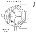
- the wheel 1, which is in the Fig. 1 and Fig. 2 is basically made of a rim 2, which is made for example in aluminum or magnesium die casting and a tire mounted thereon 3.
- the rim 2 has a bore 4 for receiving the wheel axle, not shown, and the wheel bearing.
- the rim 2 has on its outer periphery on both sides in each case a bearing section 5. Between these bearing sections 5 extend arcuately a plurality of support elements 6 outwardly, which are formed as leaf springs made of metal.
- the support elements 6 are basically arranged densely over the circumference, but have a sufficient distance to allow a largely independent compression.
- additional spring elements 7 can be provided as needed be that support the support members 6 relative to the rim 2.
- fastening elements such as screws 8, are provided, which fasten the tire 3 to the circumference of the rim 2.
- the tire 3 itself is formed in three layers and consists of an outer running surface 9, a soft elastic inner layer 10 and a support layer 11.
- the running surface 9 is formed abrasion resistant and has the task to ensure the appropriate traction.
- an in Fig. 1 schematically drawn profiling 12 is provided.
- the soft elastic inner layer 10 is formed compressible and consists for example of foam rubber with a suitable stiffness or sponge rubber.
- the thickness D 2 of the soft elastic inner layer 10 in the medial plane 2a with 30 mm is about fifteen times as large as the thickness D 1 of the tread 9.
- the soft elastic inner layer 10 is so resilient that it is compressed at rated load by about half , ie the thickness D 2 decreases to half the value.
- the rated load is assumed to be a load that results in the static case when the sports equipment is loaded with an average heavy user.
- the support layer 11 serves primarily to ensure the corresponding mechanical strength at the point of connection to the support elements 6. How out Fig. 2 can be seen, the thickness of the inner layer 10 is medial largest and decreases in the lateral direction continuously. By appropriate choice of dimensions, the driving behavior can be influenced and tuned accordingly.
- annular hard rubber edges 13 are attached to the rim 2, which engage the ground from a corresponding inclination of the wheel 1 and thus can simulate an edge use of an alpine ski, since lateral movement is now largely prevented.
- Fig. 3 shows a first embodiment of the attachment of the support members 6 to the rim 2 in detail.
- the support element 6 of Fig. 3 is slidably mounted in a slot 14 which is arranged in the bearing section 5, in the longitudinal direction.
- the slot 14 is flared in its end portion to the outside.
- a spring 15 controls the movement of the support element 6 in the direction of the slot 14.
- the support member 6 is clamped in a bearing body 16, which in turn is rotatably mounted in the rim 2.
- a particularly soft spring behavior can be achieved in the vicinity of the rim 2.
- FIGS. 6, 7 and 8 show various embodiments of the support member 6 in unwound form.
- the support member 6 thickened in the central portion, so that the individual support members 6 in the assembled state have approximately uniform distances.
- the support element 6 of Fig. 7 is similar to that of Fig. 6 with the exception that a tapered section 17 is provided in the middle region. In this way, a particularly spring characteristic can be achieved in the medial area.
- a further embodiment of the support element 6 is in Fig. 8 given, in which a support member 6 is shown, which is formed as a meandering spring wire. As a result, a particularly soft spring behavior can be achieved overall.
- Fig. 8a shows a modification of the meandering execution of Fig. 8 in which the meanders are arranged partly in the circumferential direction and partly transversely thereto.
- the wheel 1 according to the invention generally has a diameter between about 23 cm and 28 cm and has a squat structure due to its relatively large width of about 15 cm. Since the tire 3 is built on pressure, that is, even in the loaded state has no internal pressure, the deformation behavior of individual sections of the tire 3 is largely independent of the current state of deformation of other sections. Particularly noteworthy is that the deformation resistance depending on the location and the angle of the force input depending on the design of the support elements 6 and their anchoring to the rim 2 can be set within wide limits, so that an optimal balance can be achieved.
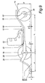
- Fig. 9 shows a sports device according to the invention in a side view in the unloaded state.
- the sports equipment consists of a frame 20 to which a front wheel 1a and a rear wheel 1b are attached.
- a binding 21 is a schematically indicated shoe 22 for the user to secure sports equipment.
- the front wheel 1a is rigidly attached via a front fork 22 to a front part 23 of the frame 20, which is pulled over the front wheel 1a.
- the rear wheel 1b is also rigidly mounted on a fork 24 of the frame 20.
- a Einarmlagerung can be provided which holds the wheel 1a, 1b only on one side with a flying stub axle.
- an extension 25 is provided which carries a support portion 26 at its end.
- the sports equipment is made of light metal to achieve the lowest possible weight with the necessary strength and rigidity.
- the extension 26 is disposed at a distance x above the bottom surface 27, wherein x is for example 10 mm.
- x is for example 10 mm.
- z 16 for the front wheel 1a
- z 20 mm for the rear wheel 1b.
- a corresponding deformation of the tires 3 of the wheels 1a, 1b can be achieved, so that the sports equipment inclines in a direction counterclockwise and the supporting portion 26 of the floor 27 contacts.
- the extension 25 is resilient, so that can adjust to a further inclination to the rear of a stronger inclination, which ultimately can also cause the front wheel 1 a lifts off the ground 27. Due to the lower cornering force of the extension 26, the steerability is significantly increased thereby.
- the diameter D of the wheels 1a, 1b at about 40% of the axial distance L.
- the diameter D of the wheels 1a, 1b between 20% and 50% of the axial distance L to choose.
- the binding 21 is arranged so that the shoe 22 ends immediately in front of the rear wheel 1b.
- the distance A of the support portion 26 from the axis 29 of the rear wheel 1b is measured horizontally about 50% of the center distance L, ie the distance of the axes 28 and 29. A range between 30% and 60% is advantageous.
- the present invention makes it possible to achieve a driving behavior which is largely similar to that of skis in deep snow.
- similar Trickschifiguren are mobile.
Landscapes
- Engineering & Computer Science (AREA)
- Mechanical Engineering (AREA)
- Tires In General (AREA)
- Pulleys (AREA)
- Golf Clubs (AREA)
- Scissors And Nippers (AREA)
- Footwear And Its Accessory, Manufacturing Method And Apparatuses (AREA)
Description
- Die Erfindung betrifft ein Rad für ein Sportgerät, insbesondere für den Grasschilauf, gemäß dem Oberbegriff von Patentanspruch 1.
- Es besteht zunehmender Bedarf an neuartigen Sportgeräten, die eine Erweiterung des Spektrums von Freizeitaktivitäten ermöglichen. Eine Form von Sportgeräten sind solche, die eine dem Schifahren ähnliche Abfahrt auf schneefreien Hängen ermöglichen, also zum sogenannten Grasschilauf dienen. Solche Sportgeräte sind im Allgemeinen ähnlich wie Schier aufgebaut, d.h. sie sind länglich mit einer Bindung zur Befestigung an einem Schuh, besitzen jedoch mindestens zwei Rollen an Stelle der Laufflächen von Schiern.
- Der eigentliche Grasschilauf wird auf Wiesen durchgeführt und setzt somit einen ausreichend glatten Untergrund voraus, der weitgehend frei von Hindernissen ist. In Sinn der vorliegenden Erfindung soll jedoch der Begriff Grasschilauf auch auf Aktivitäten in rauerem Gelände ausgedehnt werden, d.h. beispielsweise auf Abfahrten auf geschotterten Forststraßen und anderem Untergrund. Das Sportgerät und insbesondere das Rad eines solchen Sportgeräts im Sinn der Erfindung soll daher ein weitgehend geländetaugliches Verhalten aufweisen, so dass man nicht an die Verwendung auf Wiesen gebunden ist.
- Eine weitere Anforderung, die an ein Sportgerät gestellt wird, ist, dass die Beherrschung möglichst leicht erlernbar ist und dass das Fahrverhalten angenehm ist und der Bewegungsablauf möglichst physiologisch ist, um Schädigungen des Bewegungsapparates zu vermeiden. Ein im Allgemeinen als sehr angenehm empfundener Bewegungsablauf, der die obigen Forderungen erfüllt, ist der sich beim Tiefschneefahren mit Schiern einstellende. Es ist daher wünschenswert, ein Sportgerät zu schaffen, das in seinem Fahrverhalten so weit wie möglich an einen Schi herankommt, der im Tiefschnee gefahren wird. Es soll insbesondere das Verhalten beim Drehen und beim Lastwechsel die Tiefschneefahrt simulieren.
- Eine wesentliche Voraussetzung für das Erreichen des oben beschriebenen Fahrverhaltens ist eine entsprechende Ausbildung der Räder des Sportgeräts. Diese müssen einerseits eine bestimmte Geländegängigkeit ermöglichen und andererseits durch ihre Elastizität ein entsprechendes Lenkverhalten gewährleisten, um Richtungswechsel wie beim Schifahren zu ermöglichen.
- Aus der
WO 00/27490 WO 98/41295 - Auch mit Rädern, die herkömmlicher Weise mit Luftreifen ausgestattet sind, wie sie etwa in der
US 5,535,800 A offenbart sind, kann das Fahrverhalten nicht entsprechend dem gewünschten Tiefschneefahrverhalten angepasst werden. - Die
US 2,951,523 A zeigt einen Fahrzeugreifen, der als drucklose Reifen ausgebildet ist und in seinem Inneren Stützelemente aufweist, die dazu dienen die Belastbarkeit zu erhöhen. Besondere Eigenschaften hinsichtlich des Abrollverhaltens oder der seitlichen Flexibilität sind hier nicht angesprochen. - Aufgabe der Erfindung ist es, diese Nachteile zu vermeiden und ein Rad zu schaffen, mit welchem ein Fahrverhalten erreichbar wird, das weitgehend dem Schifahren in Tiefschnee entspricht. Insbesondere soll dabei ein Bewegungsablauf gefördert werden, der ergonomisch sinnvoll ist und der nicht nur keine gesundheitlichen Schäden verursacht, sondern auch therapeutisch wirksam ist.
- Erfindungsgemäß werden diese Aufgaben durch die Merkmale von Patentanspruch 1 gelöst.
- Wesentlich an der Erfindung ist die Kombination von Stützelementen, die einen ersten, größeren Teil des Federverhaltens des Rades bereitstellen, mit einer in Dickenrichtung elastischen Schicht, die einen weiteren Teil der Federwirkung ergibt. In überraschender Weise hat sich herausgestellt, dass diese Kombination von Bauelementen nicht nur eine entsprechende Geländegängigkeit ergibt, sondern auch ein Fahrverhalten zur Folge hat, das dem Fahren im Tiefschnee weitgehend ähnlich ist. Dies bedeutet, dass bis zu einer bestimmten Querkraft, die auf das Rad quer zur Fahrtrichtung wirkt, ein stabiler Geradeauslauf gewährleistet ist. Wird jedoch diese Querkraft überschritten, so erfolgt eine erntsprechende Verformung des Reifens im Bereich der Aufstandsfläche, so dass das Rad eine Bewegungskomponente quer zur eigentlichen Laufrichtung erhält. Da die Querkraftgrenze, ab der die Querbewegung beginnt, von der Belastung des Rades abhängt und die Größe der Bewegungskomponente quer zur Laufrichtung mit zunehmenden Neigung des Rades gegenüber einer senkrechten Ebene abnimmt, wird eine weitgehende Übereinstimmung mit dem Tiefschneefahren erreicht.
- Gemäß einer vorteilhaften Ausführungsvariante der Erfindung ist vorgesehen, dass der erste und der zweite Lagerabschnitt an einander gegenüberliegenden Seiten des äußeren Umfangs der Felge angeordnet sind. Dadurch wird ein besonders robuster Aufbau des Rades erreicht.
- Ein besonders vorteilhaftes Fahrverhalten kann dadurch erreicht werden, dass eine Vielzahl von Stützelementen vorgesehen ist, die in Umfangsrichtung im Abstand nebeneinander angeordnet sind. Das Einfedern des Reifens an einer Stelle, d.h. im Allgemeinen an der Aufstandsfläche kann dadurch weitgehend von der Verformung an anderen Stellen entkoppelt werden. Dies steht im Gegensatz zu Luftreifen, bei denen die Federwirkung durch den inneren Überdruck bewirkt wird. Durch den Druck und die Zugspannung im Schlauch oder im Mantel hängen die Verformungen zumindest von benachbarten Bereichen zusammen, so dass sich ein bestimmtes Fahrverhalten ergibt, das beispielsweise für Motorräder durchaus günstig und vorteilhaft ist. Schier können damit jedoch nur unzureichend simuliert werden.
- Besonders günstig ist es, wenn die Stützelemente als Metall-Blattfedern ausgebildet sind. Die Federcharakteristik kann dabei in einer Richtung quer zum Umfang des Rades nach verschiedenen Gesichtspunkten optimiert werden. Es ist alternativ auch möglich, dass die Stützelemente als mäanderförmige Federdrähte ausgebildet sind. Dadurch können besonders weiche Federn realisiert werden.
- In einer weiteren bevorzugten Ausführungsvariante der Erfindung können zusätzliche Federelemente zur Abstützung der Stützelemente vorgesehen sein. Dadurch werden weitere Freiheitsgrade bei der Feinabstimmung des Rades erreicht.
- Besondere Vorteile ergeben sich erfindungsgemäß dadurch, dass der Reifen dreischichtig aufgebaut ist und aus einer Lauffläche, einer weich-elastischen Innenschicht und einer Auflageschicht besteht. Die Auflageschicht ist dabei mechanisch widerstandsfähig, um der Reibung an den Federelementen zu widerstehen. Die Lauffläche weist die für das jeweilige Gelände optimale Profilierung und eine geeignete Verschleißfestigkeit auf. Die weich-elastische Innenschicht ist in Dickenrichtung elastisch und ermöglicht ein feines Federverhalten.
- Eine weitere besonders begünstigte Ausführungsvariante der Erfindung sieht an der Felge neben dem Reifen ein Eingriffselement vor, das sich entlang des Umfangs der Felge erstreckt. Dadurch kann der Eingriff der Kanten simuliert werden, der beim Fahren im Tiefschnee erst ab einem bestimmten Neigungswinkel in Querrichtung wirksam wird.
- Eine weitere Verbesserung des Fahrverhaltens kann dadurch erreicht werden, dass der Reifen drucklos ausgebildet ist. Besonders günstig ist es auch, wenn der Außendurchmesser der Felge etwa dem halben Durchmesser des Reifens entspricht.
- Weiters betrifft die Erfindung ein Sportgerät, insbesondere für den Grasschilauf mit einem in Längsrichtung verlaufenden Rahmen, an dem mindestens zwei Räder mit elastisch verformbaren Reifen starr gelagert sind, mit einer Bindung zur Befestigung des Sportgeräts an einem Schuh einer das Sportgerät benützenden Person, wobei ein vorderes Rad vor der Bindung angeordnet ist und wobei ein hinteres Rad hinter der Bindung angeordnet ist.
- Erfindungsgemäß ist ein solches Sportgerät dadurch gegenzeichnet, dass am Rahmen hinter dem hinteren Rad ein Fortsatz vorgesehen ist, der an seinem Ende einen Stützabschnitt aufweist, der durch Gewichtsverlagerung von einer Stellung oberhalb des Bodens in eine Stellung bringbar ist, in der er den Boden berührt und dass mindestens ein Rad wie oben beschrieben ausgebildet ist.
- Ein solches Sportgerät ermöglicht im Zusammenhang mit dem oben beschriebenen Rad ein besonders vorteilhaftes Fahrverhalten. Durch den Fortsatz kann lediglich durch Gewichtsverlagerung das Fahrverhalten wesentlich verändert werden. Bei neutraler Belastung steht das Sportgerät mit den Rädern am Boden auf, der Stützabschnitt berührt den Boden jedoch nicht. Durch eine entsprechende Gewichtsverlagerung wird das vordere Rad entlastet und das hintere Rad starker belastet. Da die Räder entsprechend weich ausgebildet sind, erfolgt durch das geänderte Einfedern eine Neigung des Sportgeräts nach hinten, so dass der Stützabschnitt am Boden aufliegt. Da der Stützabschnitt im Gegensatz zu den Rädern praktisch keine Seitenführungskraft aufweist, wird die Drehbarkeit in diesem Zustand wesentlich erleichtert. Dies entspricht weitgehend dem Fahrverhalten von Schiern im Tiefschnee, die durch Gewichtsverlagerung nach hinten entsprechend leichter drehbar sind.
- Je nach Stärke der Gewichtsverlagerung bleibt das vordere Rad zunächst entlastet am Boden, kann jedoch durch stärkere Gewichtsverlagerung zum Abheben gebracht werden.
- In einer bevorzugten Ausführungsvariante ist vorgesehen, dass der Fortsatz federnd am Rahmen befestigt ist. Dadurch kann ein entsprechend weicher Übergang im Fahrverhalten gewährleistet werden. Zusätzlich oder alternativ dazu kann jedoch auch vorgesehen sein, dass der Fortsatz elastisch ist.
- Besonders vorteilhaft ist es, wenn der Stützabschnitt plattenförmig ausgebildet ist. Durch die Berührung des Stützabschnitts mit dem Boden wird neben den oben beschriebenen Wirkungen auch eine gewisse Bremsung hervorgerufen, was an sich nicht unerwünscht ist. Die Bremswirkung soll jedoch in Grenzen gehalten werden, um keine Abweichung vom gewünschten Verhalten zu verursachen. Die plattenförmige Ausbildung des Stützabschnitts ist in dieser Hinsicht optimal.
- Ein besonders vorteilhafter Aufbau des Sportgeräts wird erreicht, wenn der Durchmesser der Räder zwischen 20% und 50%, vorzugsweise etwa 30% des Achsabstandes beträgt.
- In einer besonders begünstigten Ausführungsvariante der Erfindung ist vorgesehen, dass die Bindung unmittelbar vor dem hinteren Rad angeordnet ist. Dadurch wird der Wechsel des Fahrverhaltens durch Gewichtsverlagerung begünstigt.
- Die Erfindung wird im Folgenden anhand der in den Figuren dargestellten Ausführungsvarianten näher erläutert. Es zeigen:
- Fig. 1
- ein erfindungsgemäßes Rad in einer ersten Ausführungsvariante in einer Ansicht,
- Fig. 2
- einen Schnitt nach Linie II - II in
Fig. 1 ; - Fig. 3,
-
Fig. 4, Fig. 5 verschiedene Ausführungsvarianten der Lagerung eines Stützelementes im Detail in vergrößertem Maßstab; - Fig. 6,
-
Fig. 7, Fig. 8 und Fig. 8a verschiedene Ausführungsvarianten von Stützelementen; und - Fig. 9
- schematisch ein erfindungsgemäßes Sportgerät in einer seitlichen Ansicht.
- Das Rad 1, das in den
Fig. 1 undFig. 2 dargestellt ist, besteht grundsätzlich aus einer Felge 2, die beispielsweise in Aluminium- oder Magnesiumdruckguss hergestellt ist und einen darauf befestigten Reifen 3. Die Felge 2 besitzt eine Bohrung 4 zur Aufnahme der nicht dargestellten Radachse und der Radlager. Die Felge 2 besitzt an ihrem äußeren Umfang beidseits jeweils eine Lagerabschnitt 5. Zwischen diesen Lagerabschnitten 5 erstrecken sich bogenförmig mehrere Stützelemente 6 nach außen, die als Blattfedern aus Metall ausgebildet sind. Die Stützelemente 6 sind über den Umfang grundsätzlich dicht angeordnet, besitzen jedoch einen ausreichenden Abstand, um ein weitgehend unabhängiges Einfedern zu ermöglichen. Um die Federcharakteristik je nach Richtung einer Krafteinwirkung zu verändern, können nach Bedarf zusätzliche Federelemente 7 vorgesehen sein, die die Stützelemente 6 gegenüber der Felge 2 abstützen. Auf den Stützelementen 6 liegt der Reifen 3 frei auf. Um den korrekten Sitz zu gewährleisten, sind Befestigungselemente, wie etwa Schrauben 8, vorgesehen, die den Reifen 3 am Umfang der Felge 2 befestigt. - Der Reifen 3 selbst ist dreischichtig ausgebildet und besteht aus einer äußeren Lauffläche 9, einer weichelastischen Innenschicht 10 und einer Auflageschicht 11. Die Lauffläche 9 ist abriebfest ausgebildet und hat die Aufgabe, die entsprechende Bodenhaftung zu gewährleisten. Zu diesem Zweck ist eine in
Fig. 1 schematisch eingezeichnete Profilierung 12 vorgesehen. Die weichelastische Innenschicht 10 ist kompressibel ausgebildet und besteht beispielsweise aus Schaumgummi mit einer geeigneten Steifigkeit oder aus Moosgummi. Im unbelasteten Zustand ist die Dicke D2 der weichelastischen Innenschicht 10 in der Medialebene 2a mit 30 mm etwa fünfzehnmal so groß wie die Dicke D1 der Lauffläche 9. Die weichelastische Innenschicht 10 ist so nachgiebig, dass sie bei Nennbelastung um etwa die Hälfte zusammengedrückt wird, d.h. die Dicke D2 auf den halben Wert zurückgeht. Als Nennbelastung wird eine Belastung angenommen, die sich im statischen Fall ergibt, wenn das Sportgerät mit einem durchschnittlich schweren Benutzer belastet ist. - Die Auflageschicht 11 dient primär dazu, an der Verbindungsstelle zu den Stützelementen 6 die entsprechende mechanische Festigkeit zu gewährleisten. Wie aus
Fig. 2 ersichtlich ist, ist die Dicke der Innenschicht 10 medial am größten und nimmt in lateraler Richtung kontinuierlich ab. Durch die entsprechende Wahl der Abmessungen kann das Fahrverhalten entsprechend beeinflusst und abgestimmt werden. Seitlich neben dem Basisbereich des Reifens 3 sind an der Felge 2 ringförmige Hartgummikanten 13 angebracht, die ab einer entsprechenden Neigung des Rades 1 in Eingriff mit dem Untergrund kommen und damit einen Kanteneinsatz eines Alpinschis simulieren können, da nunmehr eine Lateralbewegung weitgehend verhindert wird. -
Fig. 3 zeigt eine erste Ausführungsvariante der Befestigung der Stützelemente 6 an der Felge 2 im Detail. Das Stützelement 6 vonFig. 3 ist in einem Schlitz 14, der im Lagerabschnitt 5 angeordnet ist, in Längsrichtung verschiebbar gelagert. Um eine entsprechende Auslenkung des Stützelementes 6 zu ermöglichen, ist der Schlitz 14 in seinem Endabschnitt nach außen konisch erweitert. Eine Feder 15 steuert die Bewegung des Stützelementes 6 in Richtung des Schlitzes 14. - Bei der Ausführungsvariante von
Fig. 4 ist das Stützelement 6 fest in der Felge 2 eingespannt. Bei dieser Ausführungsvariante wird im Bereich der Felge 2 eine wesentlich höhere Steifigkeit erzielt. - Bei der Ausführungsvariante von
Fig. 5 ist das Stützelement 6 in einem Lagerkörper 16 eingespannt, der seinerseits drehbar in der Felge 2 gelagert ist. Bei dieser Ausführungsvariante kann in der Umgebung der Felge 2 ein besonders weiches Federverhalten erzielt werden. - Die
Fig. 6, Fig. 7 und Fig. 8 zeigen verschiedene Ausführungsvarianten des Stützelementes 6 in abgewickelter Form. Bei der Ausführungsvariante vonFig. 6 ist das Stützelement 6 im mittleren Abschnitt verdickt, so dass die einzelnen Stützelemente 6 in zusammengebautem Zustand etwa gleichmäßige Abstände aufweisen. - Das Stützelement 6 von
Fig. 7 ist ähnlich aufgebaut wie das vonFig. 6 mit der Ausnahme, dass im mittleren Bereich ein verjüngter Abschnitt 17 vorgesehen ist. Auf diese Weise kann im medialen Bereich eine besonders Federkennlinie erzielt werden. Eine weitere Ausführungsvariante des Stützelementes 6 ist inFig. 8 gegeben, in der ein Stützelement 6 dargestellt ist, das als mäanderförmiger Federdraht ausgebildet ist. Dadurch kann insgesamt ein besonders weiches Federverhalten erzielt werden.Fig. 8a zeigt eine Abwandlung der mäanderförmigen Ausführung vonFig. 8 , bei der die Mäander zum Teil in Umfangsrichtung und zum Teil quer dazu angeordnet sind. - Das erfindungsgemäße Rad 1 besitzt im Allgemeinen einen Durchmesser zwischen etwa 23 cm und 28 cm und besitzt aufgrund seiner relativ großen Breite von etwa 15 cm einen gedrungenen Aufbau. Da der Reifen 3 drucklos auf gebaut ist, das heißt, auch im belasteten Zustand keinen inneren Überdruck aufweist, ist das Verformungsverhalten einzelner Abschnitte des Reifens 3 weitgehend unabhängig von dem aktuellen Verformungszustand anderer Abschnitte. Besonders hervorzuheben ist, dass sich der Verformungswiderstand abhängig von dem Ort und dem Winkel der Krafteinbringung je nach Ausbildung der Stützelemente 6 und ihrer Verankerung an der Felge 2 in weiten Grenzen einstellen lässt, so dass eine optimale Abstimmung erzielt werden kann.
-
Fig. 9 zeigt ein erfindungsgemäßes Sportgerät in einer seitlichen Ansicht in unbelastetem Zustand. Das Sportgerät besteht aus einem Rahmen 20, an dem ein vorderes Rad 1a und ein hinteres Rad 1b angebracht sind. Über eine Bindung 21 ist ein schematisch angedeuteter Schuh 22 für den Benützer Sportgerätes zu befestigen. Das vordere Rad 1a ist über eine Vordergabel 22 starr an einem Vorderteil 23 des Rahmens 20 befestigt, der über das vordere Rad 1a gezogen ist. Das hintere Rad 1b ist an einer Gabel 24 des Rahmens 20 ebenfalls starr gelagert. An Stelle einer Gabel im eigentlichen Sinn kann auch eine Einarmlagerung vorgesehen sein, die das Rad 1a, 1b nur auf einer Seite mit einem fliegenden Achsstummel hält. - Am hinteren Ende der Gabel 24 ist ein Fortsatz 25 vorgesehen, der an seinem Ende einen Stützabschnitt 26 trägt. Das Sportgerät ist aus Leichtmetall hergestellt, um bei notwendiger Festigkeit und Steifigkeit ein möglichst geringes Gewicht zu erreichen.
- Bei gleichmäßig belastetem Sportgerät, d.h. wenn der Schwerpunkt der das Sportgerät benützenden Person im Wesentlichen über dem Schuh 22 liegt, ist der Fortsatz 26 in einem Abstand x oberhalb der Bodenoberfläche 27 angeordnet, wobei x beispielsweise 10 mm beträgt. Die in
Fig. 9 nur angedeutete Verformung der Räder 1a, 1b um einen Weg z bzw. y beträgt dann beispielsweise z = 16 für das vordere Rad 1a und z= 20 mm für das Hinterrad 1b. Durch Gewichtsverlagerung nach hinten kann jedoch eine entsprechende Verformung der Reifen 3 der Räder 1a, 1b erzielt werden, so dass sich das Sportgerät in einer Richtung entgegen der Richtung des Uhrzeigersinns neigt und der Stützabschnitt 26 des Boden 27 berührt. Die Berührung des Stützabschnitts 26 tritt ein, wenn durch die Gewichtsverlagerung das vordere Rad 1a auf z = 10 mm entlastet ist und das hintere Rad 1b auf y = 26 mm zusätzlich belastet ist. Da das vordere Rad 1a noch teilweise belastet ist kann noch eine Seitenführungskraft übernommen werden. Diese wird allerdings durch weitere Entlastung des vorderen Rades 1a weiter verringert, wobei diese Verringerung kontinuierlich erfolgt und nicht abrupt, wie es der Fall wäre, wenn das vordere Rad 1a sofort abhebt. Eine Mindestverformung von 15 mm bei Nennlast hat sich als Untergrenze für einen optimalen Betrieb des Sportgeräts herausgestellt. - Der Fortsatz 25 ist federnd ausgebildet, so dass sich bei weiterer Gewichtsverlagerung nach hinten eines stärkere Neigung einstellen kann, die letztlich auch dazu führen kann, dass das vordere Rad 1a vom Boden 27 abhebt. Aufgrund der geringeren Seitenführungskraft des Fortsatzes 26 wird dadurch die Lenkbarkeit wesentlich erhöht. Bei der Ausführungsvariante von
Fig. 9 ist der Stützabschnitt 26 plattenförmig ausgebildet, für das Fahren auf Asphalt kann jedoch auch an dieser Stelle eine Rolle vorgesehen sein, um die Geräuschentwicklung und den Widerstand zu verringern. - Bei der dargestellten Ausführungsvariante liegt der Durchmesser D der Räder 1a, 1b bei etwa 40% des Achsabstandes L. Je nach Ausführungsvariante ist der Durchmesser D der Räder 1a, 1b zwischen 20% und 50% des Achsabstandes L zu wählen. Weiters ist aus
Fig. 9 ersichtlich, dass die Bindung 21 so angeordnet ist, dass der Schuh 22 unmittelbar vor dem hinteren Rad 1b endet. - Der Abstand A des Stützabschnitts 26 von der Achse 29 des hinteren Rades 1b beträgt horizontal gemessen etwa 50% des Achsabstandes L, d.h. des Abstandes der Achsen 28 und 29. Ein Bereich zwischen 30% und 60% ist vorteilhaft.
- Die vorliegende Erfindung ermöglicht es, ein Fahrverhalten zu erreichen, das dem von Schiern im Tiefschnee weitgehend ähnlich ist. Insbesondere sind ähnliche Trickschifiguren fahrbar.
Claims (11)
- Rad (1, 1a, 1b), insbesondere für ein Sportgerät für den Grasschilauf oder dergleichen, mit einer Felge (2) und einem an der Felge (2) befestigten Reifen (3) mit einer Lauffläche (9) und mit mindestens einem federnd ausgebildeten Stützelement (6) für den Reifen (3), das sich bogenförmig von einem ersten Lagerabschnitt (5) zu einem zweiten Lagerabschnitt (5) erstreckt und das den Reifen (3) im Wesentlichen in seinem gesamten Querschnittsverlauf unterstützt, dadurch gekennzeichnet, dass der Reifen (3) aus mehreren Schichten besteht und an die Lauffläche zum Radinneren hin anschließend eine in Dickenrichtung elastische Schicht (10) aufweist und dass eine Vielzahl von Stützelementen (6) vorgesehen ist, die in Umfangsrichtung im Abstand nebeneinander angeordnet sind.
- Rad (1; 1a, 1b) nach Anspruch 1, dadurch gekennzeichnet, dass der erste und der zweite Lagerabschnitt (5) an einander gegenüberliegenden Seiten des äußeren Umfangs der Felge (2) angeordnet sind.
- Rad (1; 1a, 1b) nach einem der Ansprüche 1 oder 2, dadurch gekennzeichnet, dass in Dickenrichtung elastische Schicht (10) aus Moosgummi aufgebaut ist und in der Medialebene (2a) eine Dicke (D2) aufweist, die mindestens fünfmal, vorzugsweise zehnmal so groß ist wie die Dicke (D1) der Lauffläche (9).
- Rad (1; 1a, 1b) nach Anspruch 1 bis 3, dadurch gekennzeichnet, dass die Stützelemente (6) als mäanderförmige Federdrähte ausgebildet sind.
- Rad (1; 1a, 1b) nach einem der Ansprüche 1 bis 4, dadurch gekennzeichnet, dass zusätzliche Federelemente zur Abstützung der Stützelemente (6) vorgesehen sind.
- Rad (1; 1a, 1b) nach einem der Ansprüche 1 bis 5, dadurch gekennzeichnet, dass das Stützelement (6) an der Felge (2) eingespannt, gelenkig gelagert oder federnd verschiebbar gelagert ist.
- Rad (1; 1a, 1b) nach einem der Ansprüche 1 bis 6, dadurch gekennzeichnet, dass der Reifen (3) beidseits mit der Felge (2) fest verbunden ist und auf dem Stützelement (6) frei aufliegt.
- Rad (1; 1a, 1b) nach einem der Ansprüche 1 bis 7, dadurch gekennzeichnet, dass der vorzugsweise drucklos ausgebildete Reifen (3) dreischichtig aufgebaut ist und aus einer Lauffläche (9), einer weich-elastischen Innenschicht (10) und einer Auflageschicht (11) besteht.
- Rad (1; 1a, 1b) nach einem der Ansprüche 1 bis 8, dadurch gekennzeichnet, dass an der Felge (2) neben dem Reifen (3) ein Eingriffselement (13) vorgesehen ist, das sich entlang des Umfangs der Felge (2) erstreckt.
- Rad (1; 1a, 1b) nach einem der Ansprüche 1 bis 9, dadurch gekennzeichnet, dass der Außendurchmesser der Felge (2) etwa dem halben Außendurchmesser (D) des Reifens (3) entspricht.
- Sportgerät, insbesondere für den Grasschilauf, mit einem in Längsrichtung verlaufenden Rahmen (20), an dem mindestens zwei Räder (1; 1a, 1b) mit elastisch verformbaren Reifen (3) starr gelagert sind, mit einer Bindung (21) zur Befestigung des Sportgeräts an einem Schuh (22) einer das Sportgerät benützenden Person, wobei ein vorderes Rad (1a) vor der Bindung (21) angeordnet ist und wobei ein hinteres Rad (1b) hinter der Bindung (21) angeordnet ist, und wobei am Rahmen (20) hinter dem hinteren Rad (1b) ein zum Lenken des Sportgeräts bestimmter Fortsatz (25) vorgesehen ist, der an seinem distalen Ende einen Stützabschnitt (26) aufweist, dadurch gekennzeichnet, dass der vorzugsweise federnd am Rahmen befestigte oder elastische Fortsatz (25) durch Gewichtsverlagerung von einer Stellung oberhalb des Bodens (27) in eine Stellung bringbar ist, in der er aufgrund ausreichender Verformbarkeit der Räder (1; 1a, 1b) gleichzeitig mit dem vorderen und dem hinteren Rad (1a, 1b) den Boden (27) berührt, und dass mindestens ein Rad (1; 1a, 1b) nach einem der Ansprüche 1 bis 10 ausgebildet ist.
Applications Claiming Priority (3)
| Application Number | Priority Date | Filing Date | Title |
|---|---|---|---|
| AT0000403A AT412384B (de) | 2003-01-02 | 2003-01-02 | Laufrad für ein sportgerät |
| AT42003 | 2003-01-02 | ||
| PCT/AT2003/000386 WO2004060506A1 (de) | 2003-01-02 | 2003-12-23 | Rad |
Publications (2)
| Publication Number | Publication Date |
|---|---|
| EP1578507A1 EP1578507A1 (de) | 2005-09-28 |
| EP1578507B1 true EP1578507B1 (de) | 2008-04-09 |
Family
ID=32686565
Family Applications (1)
| Application Number | Title | Priority Date | Filing Date |
|---|---|---|---|
| EP03779555A Expired - Lifetime EP1578507B1 (de) | 2003-01-02 | 2003-12-23 | Rad |
Country Status (6)
| Country | Link |
|---|---|
| US (1) | US20060113832A1 (de) |
| EP (1) | EP1578507B1 (de) |
| AT (2) | AT412384B (de) |
| AU (1) | AU2003287759A1 (de) |
| DE (1) | DE50309600D1 (de) |
| WO (1) | WO2004060506A1 (de) |
Families Citing this family (2)
| Publication number | Priority date | Publication date | Assignee | Title |
|---|---|---|---|---|
| AT502057B1 (de) | 2005-06-30 | 2007-05-15 | Mario Dr Herzog | Rad |
| CN104742661A (zh) * | 2015-04-08 | 2015-07-01 | 宁波易凡工业设计有限公司 | 一种免充气自行车轮胎 |
Family Cites Families (26)
| Publication number | Priority date | Publication date | Assignee | Title |
|---|---|---|---|---|
| DE654228C (de) * | 1937-12-15 | Otto Rossbach | Lenkbarer einspuriger Zweiradrollschuh | |
| GB191125342A (en) * | 1911-02-11 | 1912-04-25 | John Warren Burges | Improvements in Tires. |
| US1539445A (en) * | 1922-11-24 | 1925-05-26 | Theodoor Van Buuren | Wheel skate |
| US1498603A (en) * | 1923-01-03 | 1924-06-24 | Andrews Oscar | Resilient wheel |
| US1965484A (en) * | 1933-06-01 | 1934-07-03 | John K Bables | Resilient wheel |
| FR787097A (fr) * | 1934-06-05 | 1935-09-16 | Ski roulant | |
| FR800880A (fr) * | 1935-04-23 | 1936-07-21 | Appareil de sport et de jeux | |
| US2912032A (en) * | 1957-06-20 | 1959-11-10 | Ray H Alexander | Spring tire |
| US2951523A (en) * | 1958-11-24 | 1960-09-06 | Maco Ind Inc | Pressureless tires |
| US3208500A (en) * | 1961-06-23 | 1965-09-28 | Bayer Ag | Vehicle tire |
| DE1505029A1 (de) * | 1965-10-25 | 1969-06-04 | Hans Faber | Reifen,insbesondere fuer Kraftfahrzeuge |
| US3814157A (en) * | 1971-12-16 | 1974-06-04 | E Kowatch | Non-pneumatic vehicle wheel |
| US3767220A (en) * | 1972-03-13 | 1973-10-23 | R Peterson | Foot worn two-wheeled vehicle |
| US3923316A (en) * | 1973-12-27 | 1975-12-02 | Richard S Birnbaum | Grass-ski |
| IT1267843B1 (it) * | 1994-07-28 | 1997-02-18 | Bortoli Giuseppe De | Ruota per pattini ammortizzata |
| US5535800A (en) * | 1994-11-21 | 1996-07-16 | The Goodyear Tire & Rubber Company | Pneumatic tire for extended mobility featuring composite ribs |
| DE19624067A1 (de) * | 1996-06-17 | 1997-12-18 | Continental Ag | Karkasse eines Fahrzeugluftreifens |
| AU7204698A (en) * | 1997-03-17 | 1998-10-12 | Viktor Schatz | Wheel and belt drive with transversal brake |
| FR2767710B1 (fr) * | 1997-08-28 | 1999-10-22 | Salomon Sa | Roue pour patin a roulettes munie d'une bande de roulement |
| DE19851825B4 (de) * | 1998-11-10 | 2011-09-15 | Litens Automotive Gmbh | Laufradanordnung |
| DE19934906C2 (de) * | 1999-07-21 | 2001-05-17 | Frank Munser | Gerät zur Fortbewegung von Personen |
| US7108331B2 (en) * | 2000-02-28 | 2006-09-19 | Myron Stuart Hurwitz | Generation of in-line skates and skate-boards with safety “EDGING FRICTION CONTROL™” |
| US6637827B2 (en) * | 2000-02-28 | 2003-10-28 | Myron Stuart Hurwitz | Generation of in-line skates and skate-boards wtih safety “edging friction control™” |
| DE10013413C2 (de) * | 2000-03-17 | 2003-06-05 | Harry Gaus | Rollsportgerät |
| US7090306B1 (en) * | 2003-06-12 | 2006-08-15 | Piper Neal W | Inline wheel with softer tire and internal support structure |
| US7172205B1 (en) * | 2004-05-28 | 2007-02-06 | Vujtech James A | Two-wheeled riding-board apparatus |
-
2003
- 2003-01-02 AT AT0000403A patent/AT412384B/de active
- 2003-12-23 EP EP03779555A patent/EP1578507B1/de not_active Expired - Lifetime
- 2003-12-23 WO PCT/AT2003/000386 patent/WO2004060506A1/de not_active Ceased
- 2003-12-23 US US10/541,249 patent/US20060113832A1/en not_active Abandoned
- 2003-12-23 AU AU2003287759A patent/AU2003287759A1/en not_active Abandoned
- 2003-12-23 AT AT03779555T patent/ATE391538T1/de not_active IP Right Cessation
- 2003-12-23 DE DE50309600T patent/DE50309600D1/de not_active Expired - Lifetime
Also Published As
| Publication number | Publication date |
|---|---|
| AU2003287759A1 (en) | 2004-07-29 |
| WO2004060506A1 (de) | 2004-07-22 |
| ATA42003A (de) | 2004-07-15 |
| ATE391538T1 (de) | 2008-04-15 |
| US20060113832A1 (en) | 2006-06-01 |
| AT412384B (de) | 2005-02-25 |
| DE50309600D1 (de) | 2008-05-21 |
| EP1578507A1 (de) | 2005-09-28 |
Similar Documents
| Publication | Publication Date | Title |
|---|---|---|
| DE69834427T2 (de) | Rollbrett | |
| DE69320335T2 (de) | Fahrzeug für sport | |
| DE2925555C2 (de) | Einspuriger, lenkbarer Rollschuh | |
| EP0858359B1 (de) | Einspuriger rollschuh und laufrollen zur verwendung an einem solchen | |
| EP0486013A1 (de) | Sportgerät | |
| DE102007031237B4 (de) | Kippwinkel-gelenktes Rollgerät mit versetzten Rollen | |
| DE10013413C2 (de) | Rollsportgerät | |
| AT412384B (de) | Laufrad für ein sportgerät | |
| AT516463B1 (de) | Skiroller | |
| AT519346B1 (de) | Tretroller | |
| AT412256B (de) | Sportgerät | |
| AT502057B1 (de) | Rad | |
| DE19700589A1 (de) | Rad mit einem drehbaren Reifen | |
| DE29612000U1 (de) | Rollschuh | |
| EP0979128A1 (de) | Sportgerät mit einer zweispurigen rollvorrichtung | |
| AT403662B (de) | Einspuriger rollschuh und satz von laufrollen (set) für einen solchen | |
| DE19831652A1 (de) | Sportgerät | |
| DE3027682A1 (de) | Rollschuhe fuer rauhe boeden | |
| DE102013224611B4 (de) | Skiroller | |
| DE202005017345U1 (de) | Einspuriges Rollsportgerät | |
| AT403660B (de) | Einspuriger rollschuh und laufrollensatz für einen solchen | |
| DE202009001210U1 (de) | Roller | |
| DE2701761A1 (de) | Skate-board | |
| DE29903257U1 (de) | Freizeitsportgerät | |
| DE20022650U1 (de) | Kindersportwagen |
Legal Events
| Date | Code | Title | Description |
|---|---|---|---|
| PUAI | Public reference made under article 153(3) epc to a published international application that has entered the european phase |
Free format text: ORIGINAL CODE: 0009012 |
|
| 17P | Request for examination filed |
Effective date: 20050704 |
|
| AK | Designated contracting states |
Kind code of ref document: A1 Designated state(s): AT BE BG CH CY CZ DE DK EE ES FI FR GB GR HU IE IT LI LU MC NL PT RO SE SI SK TR |
|
| AX | Request for extension of the european patent |
Extension state: AL LT LV MK |
|
| DAX | Request for extension of the european patent (deleted) | ||
| 17Q | First examination report despatched |
Effective date: 20061107 |
|
| GRAP | Despatch of communication of intention to grant a patent |
Free format text: ORIGINAL CODE: EPIDOSNIGR1 |
|
| GRAS | Grant fee paid |
Free format text: ORIGINAL CODE: EPIDOSNIGR3 |
|
| GRAA | (expected) grant |
Free format text: ORIGINAL CODE: 0009210 |
|
| AK | Designated contracting states |
Kind code of ref document: B1 Designated state(s): AT BE BG CH CY CZ DE DK EE ES FI FR GB GR HU IE IT LI LU MC NL PT RO SE SI SK TR |
|
| REG | Reference to a national code |
Ref country code: GB Ref legal event code: FG4D Free format text: NOT ENGLISH |
|
| REG | Reference to a national code |
Ref country code: CH Ref legal event code: EP |
|
| REG | Reference to a national code |
Ref country code: IE Ref legal event code: FG4D Free format text: LANGUAGE OF EP DOCUMENT: GERMAN |
|
| REF | Corresponds to: |
Ref document number: 50309600 Country of ref document: DE Date of ref document: 20080521 Kind code of ref document: P |
|
| REG | Reference to a national code |
Ref country code: CH Ref legal event code: NV Representative=s name: ISLER & PEDRAZZINI AG |
|
| PG25 | Lapsed in a contracting state [announced via postgrant information from national office to epo] |
Ref country code: SI Free format text: LAPSE BECAUSE OF FAILURE TO SUBMIT A TRANSLATION OF THE DESCRIPTION OR TO PAY THE FEE WITHIN THE PRESCRIBED TIME-LIMIT Effective date: 20080409 |
|
| NLV1 | Nl: lapsed or annulled due to failure to fulfill the requirements of art. 29p and 29m of the patents act | ||
| PG25 | Lapsed in a contracting state [announced via postgrant information from national office to epo] |
Ref country code: BG Free format text: LAPSE BECAUSE OF FAILURE TO SUBMIT A TRANSLATION OF THE DESCRIPTION OR TO PAY THE FEE WITHIN THE PRESCRIBED TIME-LIMIT Effective date: 20080709 Ref country code: PT Free format text: LAPSE BECAUSE OF FAILURE TO SUBMIT A TRANSLATION OF THE DESCRIPTION OR TO PAY THE FEE WITHIN THE PRESCRIBED TIME-LIMIT Effective date: 20080910 Ref country code: ES Free format text: LAPSE BECAUSE OF FAILURE TO SUBMIT A TRANSLATION OF THE DESCRIPTION OR TO PAY THE FEE WITHIN THE PRESCRIBED TIME-LIMIT Effective date: 20080720 Ref country code: FI Free format text: LAPSE BECAUSE OF FAILURE TO SUBMIT A TRANSLATION OF THE DESCRIPTION OR TO PAY THE FEE WITHIN THE PRESCRIBED TIME-LIMIT Effective date: 20080409 Ref country code: NL Free format text: LAPSE BECAUSE OF FAILURE TO SUBMIT A TRANSLATION OF THE DESCRIPTION OR TO PAY THE FEE WITHIN THE PRESCRIBED TIME-LIMIT Effective date: 20080409 |
|
| REG | Reference to a national code |
Ref country code: IE Ref legal event code: FD4D |
|
| EN | Fr: translation not filed | ||
| PG25 | Lapsed in a contracting state [announced via postgrant information from national office to epo] |
Ref country code: CZ Free format text: LAPSE BECAUSE OF FAILURE TO SUBMIT A TRANSLATION OF THE DESCRIPTION OR TO PAY THE FEE WITHIN THE PRESCRIBED TIME-LIMIT Effective date: 20080409 Ref country code: IE Free format text: LAPSE BECAUSE OF FAILURE TO SUBMIT A TRANSLATION OF THE DESCRIPTION OR TO PAY THE FEE WITHIN THE PRESCRIBED TIME-LIMIT Effective date: 20080409 Ref country code: SE Free format text: LAPSE BECAUSE OF FAILURE TO SUBMIT A TRANSLATION OF THE DESCRIPTION OR TO PAY THE FEE WITHIN THE PRESCRIBED TIME-LIMIT Effective date: 20080709 Ref country code: DK Free format text: LAPSE BECAUSE OF FAILURE TO SUBMIT A TRANSLATION OF THE DESCRIPTION OR TO PAY THE FEE WITHIN THE PRESCRIBED TIME-LIMIT Effective date: 20080409 |
|
| PGFP | Annual fee paid to national office [announced via postgrant information from national office to epo] |
Ref country code: CH Payment date: 20081229 Year of fee payment: 6 |
|
| PLBE | No opposition filed within time limit |
Free format text: ORIGINAL CODE: 0009261 |
|
| STAA | Information on the status of an ep patent application or granted ep patent |
Free format text: STATUS: NO OPPOSITION FILED WITHIN TIME LIMIT |
|
| PG25 | Lapsed in a contracting state [announced via postgrant information from national office to epo] |
Ref country code: SK Free format text: LAPSE BECAUSE OF FAILURE TO SUBMIT A TRANSLATION OF THE DESCRIPTION OR TO PAY THE FEE WITHIN THE PRESCRIBED TIME-LIMIT Effective date: 20080409 Ref country code: RO Free format text: LAPSE BECAUSE OF FAILURE TO SUBMIT A TRANSLATION OF THE DESCRIPTION OR TO PAY THE FEE WITHIN THE PRESCRIBED TIME-LIMIT Effective date: 20080409 |
|
| ET | Fr: translation filed | ||
| REG | Reference to a national code |
Ref country code: FR Ref legal event code: EERR Free format text: CORRECTION DE BOPI 09/05 - BREVETS EUROPEENS DONT LA TRADUCTION N A PAS ETE REMISE A L INPI. IL Y A LIEU DE SUPPRIMER : LA MENTION DE LA NON-REMISE. LA REMISE DE LA TRADUCTION EST PUBLIEE DANS LE PRESENT BOPI. |
|
| 26N | No opposition filed |
Effective date: 20090112 |
|
| PG25 | Lapsed in a contracting state [announced via postgrant information from national office to epo] |
Ref country code: EE Free format text: LAPSE BECAUSE OF FAILURE TO SUBMIT A TRANSLATION OF THE DESCRIPTION OR TO PAY THE FEE WITHIN THE PRESCRIBED TIME-LIMIT Effective date: 20080409 |
|
| BERE | Be: lapsed |
Owner name: HERZOG, MARIO Effective date: 20081231 |
|
| PG25 | Lapsed in a contracting state [announced via postgrant information from national office to epo] |
Ref country code: MC Free format text: LAPSE BECAUSE OF NON-PAYMENT OF DUE FEES Effective date: 20081231 |
|
| GBPC | Gb: european patent ceased through non-payment of renewal fee |
Effective date: 20081223 |
|
| PGFP | Annual fee paid to national office [announced via postgrant information from national office to epo] |
Ref country code: IT Payment date: 20081229 Year of fee payment: 6 |
|
| PG25 | Lapsed in a contracting state [announced via postgrant information from national office to epo] |
Ref country code: CY Free format text: LAPSE BECAUSE OF FAILURE TO SUBMIT A TRANSLATION OF THE DESCRIPTION OR TO PAY THE FEE WITHIN THE PRESCRIBED TIME-LIMIT Effective date: 20080409 Ref country code: BE Free format text: LAPSE BECAUSE OF NON-PAYMENT OF DUE FEES Effective date: 20081231 |
|
| PG25 | Lapsed in a contracting state [announced via postgrant information from national office to epo] |
Ref country code: GB Free format text: LAPSE BECAUSE OF NON-PAYMENT OF DUE FEES Effective date: 20081223 |
|
| PG25 | Lapsed in a contracting state [announced via postgrant information from national office to epo] |
Ref country code: AT Free format text: LAPSE BECAUSE OF NON-PAYMENT OF DUE FEES Effective date: 20081223 |
|
| PG25 | Lapsed in a contracting state [announced via postgrant information from national office to epo] |
Ref country code: HU Free format text: LAPSE BECAUSE OF FAILURE TO SUBMIT A TRANSLATION OF THE DESCRIPTION OR TO PAY THE FEE WITHIN THE PRESCRIBED TIME-LIMIT Effective date: 20081010 Ref country code: LU Free format text: LAPSE BECAUSE OF NON-PAYMENT OF DUE FEES Effective date: 20081223 |
|
| REG | Reference to a national code |
Ref country code: CH Ref legal event code: PL |
|
| PG25 | Lapsed in a contracting state [announced via postgrant information from national office to epo] |
Ref country code: TR Free format text: LAPSE BECAUSE OF FAILURE TO SUBMIT A TRANSLATION OF THE DESCRIPTION OR TO PAY THE FEE WITHIN THE PRESCRIBED TIME-LIMIT Effective date: 20080409 |
|
| REG | Reference to a national code |
Ref country code: FR Ref legal event code: ST Effective date: 20100831 |
|
| PG25 | Lapsed in a contracting state [announced via postgrant information from national office to epo] |
Ref country code: FR Free format text: LAPSE BECAUSE OF NON-PAYMENT OF DUE FEES Effective date: 20091231 Ref country code: LI Free format text: LAPSE BECAUSE OF NON-PAYMENT OF DUE FEES Effective date: 20091231 Ref country code: CH Free format text: LAPSE BECAUSE OF NON-PAYMENT OF DUE FEES Effective date: 20091231 Ref country code: GR Free format text: LAPSE BECAUSE OF FAILURE TO SUBMIT A TRANSLATION OF THE DESCRIPTION OR TO PAY THE FEE WITHIN THE PRESCRIBED TIME-LIMIT Effective date: 20080710 |
|
| PG25 | Lapsed in a contracting state [announced via postgrant information from national office to epo] |
Ref country code: IT Free format text: LAPSE BECAUSE OF NON-PAYMENT OF DUE FEES Effective date: 20091223 |
|
| PGFP | Annual fee paid to national office [announced via postgrant information from national office to epo] |
Ref country code: DE Payment date: 20171228 Year of fee payment: 15 |
|
| REG | Reference to a national code |
Ref country code: DE Ref legal event code: R119 Ref document number: 50309600 Country of ref document: DE |
|
| PG25 | Lapsed in a contracting state [announced via postgrant information from national office to epo] |
Ref country code: DE Free format text: LAPSE BECAUSE OF NON-PAYMENT OF DUE FEES Effective date: 20190702 |