EP1578462B1 - Nadelschutzvorrichtung - Google Patents
Nadelschutzvorrichtung Download PDFInfo
- Publication number
- EP1578462B1 EP1578462B1 EP03780587.6A EP03780587A EP1578462B1 EP 1578462 B1 EP1578462 B1 EP 1578462B1 EP 03780587 A EP03780587 A EP 03780587A EP 1578462 B1 EP1578462 B1 EP 1578462B1
- Authority
- EP
- European Patent Office
- Prior art keywords
- protector
- tube
- needle
- outer tube
- syringe
- Prior art date
- Legal status (The legal status is an assumption and is not a legal conclusion. Google has not performed a legal analysis and makes no representation as to the accuracy of the status listed.)
- Expired - Lifetime
Links
- 230000001012 protector Effects 0.000 title claims description 103
- 210000002105 tongue Anatomy 0.000 description 12
- 239000012530 fluid Substances 0.000 description 4
- 241000282472 Canis lupus familiaris Species 0.000 description 3
- 208000030507 AIDS Diseases 0.000 description 2
- 108010072051 Glatiramer Acetate Proteins 0.000 description 2
- -1 but not limited to Substances 0.000 description 2
- 238000011109 contamination Methods 0.000 description 2
- 229940079593 drug Drugs 0.000 description 2
- 239000003814 drug Substances 0.000 description 2
- 210000005069 ears Anatomy 0.000 description 2
- 238000002347 injection Methods 0.000 description 2
- 239000007924 injection Substances 0.000 description 2
- 238000004519 manufacturing process Methods 0.000 description 2
- 239000000463 material Substances 0.000 description 2
- 238000005381 potential energy Methods 0.000 description 2
- 229910001220 stainless steel Inorganic materials 0.000 description 2
- 239000010935 stainless steel Substances 0.000 description 2
- 208000012260 Accidental injury Diseases 0.000 description 1
- FHEAIOHRHQGZPC-KIWGSFCNSA-N acetic acid;(2s)-2-amino-3-(4-hydroxyphenyl)propanoic acid;(2s)-2-aminopentanedioic acid;(2s)-2-aminopropanoic acid;(2s)-2,6-diaminohexanoic acid Chemical compound CC(O)=O.C[C@H](N)C(O)=O.NCCCC[C@H](N)C(O)=O.OC(=O)[C@@H](N)CCC(O)=O.OC(=O)[C@@H](N)CC1=CC=C(O)C=C1 FHEAIOHRHQGZPC-KIWGSFCNSA-N 0.000 description 1
- 238000010276 construction Methods 0.000 description 1
- 229940038717 copaxone Drugs 0.000 description 1
- 230000006378 damage Effects 0.000 description 1
- 229960003776 glatiramer acetate Drugs 0.000 description 1
- 208000006454 hepatitis Diseases 0.000 description 1
- 231100000283 hepatitis Toxicity 0.000 description 1
- 239000012678 infectious agent Substances 0.000 description 1
- 208000015181 infectious disease Diseases 0.000 description 1
- 229940071643 prefilled syringe Drugs 0.000 description 1
- 239000000126 substance Substances 0.000 description 1
- 208000011580 syndromic disease Diseases 0.000 description 1
Images


Classifications
-
- A—HUMAN NECESSITIES
- A61—MEDICAL OR VETERINARY SCIENCE; HYGIENE
- A61M—DEVICES FOR INTRODUCING MEDIA INTO, OR ONTO, THE BODY; DEVICES FOR TRANSDUCING BODY MEDIA OR FOR TAKING MEDIA FROM THE BODY; DEVICES FOR PRODUCING OR ENDING SLEEP OR STUPOR
- A61M5/00—Devices for bringing media into the body in a subcutaneous, intra-vascular or intramuscular way; Accessories therefor, e.g. filling or cleaning devices, arm-rests
- A61M5/178—Syringes
- A61M5/31—Details
- A61M5/32—Needles; Details of needles pertaining to their connection with syringe or hub; Accessories for bringing the needle into, or holding the needle on, the body; Devices for protection of needles
- A61M5/3205—Apparatus for removing or disposing of used needles or syringes, e.g. containers; Means for protection against accidental injuries from used needles
- A61M5/321—Means for protection against accidental injuries by used needles
- A61M5/3243—Means for protection against accidental injuries by used needles being axially-extensible, e.g. protective sleeves coaxially slidable on the syringe barrel
- A61M5/326—Fully automatic sleeve extension, i.e. in which triggering of the sleeve does not require a deliberate action by the user
-
- A—HUMAN NECESSITIES
- A61—MEDICAL OR VETERINARY SCIENCE; HYGIENE
- A61M—DEVICES FOR INTRODUCING MEDIA INTO, OR ONTO, THE BODY; DEVICES FOR TRANSDUCING BODY MEDIA OR FOR TAKING MEDIA FROM THE BODY; DEVICES FOR PRODUCING OR ENDING SLEEP OR STUPOR
- A61M5/00—Devices for bringing media into the body in a subcutaneous, intra-vascular or intramuscular way; Accessories therefor, e.g. filling or cleaning devices, arm-rests
- A61M5/178—Syringes
- A61M5/31—Details
- A61M5/32—Needles; Details of needles pertaining to their connection with syringe or hub; Accessories for bringing the needle into, or holding the needle on, the body; Devices for protection of needles
- A61M5/3205—Apparatus for removing or disposing of used needles or syringes, e.g. containers; Means for protection against accidental injuries from used needles
- A61M5/321—Means for protection against accidental injuries by used needles
- A61M5/3243—Means for protection against accidental injuries by used needles being axially-extensible, e.g. protective sleeves coaxially slidable on the syringe barrel
- A61M5/3245—Constructional features thereof, e.g. to improve manipulation or functioning
- A61M2005/3247—Means to impede repositioning of protection sleeve from needle covering to needle uncovering position
-
- A—HUMAN NECESSITIES
- A61—MEDICAL OR VETERINARY SCIENCE; HYGIENE
- A61M—DEVICES FOR INTRODUCING MEDIA INTO, OR ONTO, THE BODY; DEVICES FOR TRANSDUCING BODY MEDIA OR FOR TAKING MEDIA FROM THE BODY; DEVICES FOR PRODUCING OR ENDING SLEEP OR STUPOR
- A61M5/00—Devices for bringing media into the body in a subcutaneous, intra-vascular or intramuscular way; Accessories therefor, e.g. filling or cleaning devices, arm-rests
- A61M5/178—Syringes
- A61M5/31—Details
- A61M5/32—Needles; Details of needles pertaining to their connection with syringe or hub; Accessories for bringing the needle into, or holding the needle on, the body; Devices for protection of needles
- A61M5/3205—Apparatus for removing or disposing of used needles or syringes, e.g. containers; Means for protection against accidental injuries from used needles
- A61M5/321—Means for protection against accidental injuries by used needles
- A61M5/3243—Means for protection against accidental injuries by used needles being axially-extensible, e.g. protective sleeves coaxially slidable on the syringe barrel
- A61M5/3271—Means for protection against accidental injuries by used needles being axially-extensible, e.g. protective sleeves coaxially slidable on the syringe barrel with guiding tracks for controlled sliding of needle protective sleeve from needle exposing to needle covering position
-
- A—HUMAN NECESSITIES
- A61—MEDICAL OR VETERINARY SCIENCE; HYGIENE
- A61M—DEVICES FOR INTRODUCING MEDIA INTO, OR ONTO, THE BODY; DEVICES FOR TRANSDUCING BODY MEDIA OR FOR TAKING MEDIA FROM THE BODY; DEVICES FOR PRODUCING OR ENDING SLEEP OR STUPOR
- A61M5/00—Devices for bringing media into the body in a subcutaneous, intra-vascular or intramuscular way; Accessories therefor, e.g. filling or cleaning devices, arm-rests
- A61M5/50—Devices for bringing media into the body in a subcutaneous, intra-vascular or intramuscular way; Accessories therefor, e.g. filling or cleaning devices, arm-rests having means for preventing re-use, or for indicating if defective, used, tampered with or unsterile
- A61M5/5013—Means for blocking the piston or the fluid passageway to prevent illegal refilling of a syringe
- A61M5/502—Means for blocking the piston or the fluid passageway to prevent illegal refilling of a syringe for blocking the piston
-
- Y—GENERAL TAGGING OF NEW TECHNOLOGICAL DEVELOPMENTS; GENERAL TAGGING OF CROSS-SECTIONAL TECHNOLOGIES SPANNING OVER SEVERAL SECTIONS OF THE IPC; TECHNICAL SUBJECTS COVERED BY FORMER USPC CROSS-REFERENCE ART COLLECTIONS [XRACs] AND DIGESTS
- Y10—TECHNICAL SUBJECTS COVERED BY FORMER USPC
- Y10S—TECHNICAL SUBJECTS COVERED BY FORMER USPC CROSS-REFERENCE ART COLLECTIONS [XRACs] AND DIGESTS
- Y10S128/00—Surgery
- Y10S128/917—Body fluid, devices for protection therefrom, e.g. aids, hepatitus
- Y10S128/919—Syringe, means to protect user
Definitions
- the present invention relates to devices that cover medical needles and sharps, such as to protect against accidental puncture and contamination.
- Pointed hollow needles are widely employed to puncture the skin of a person, especially to perform venipuncture for many purposes, such as but not limited to, injecting fluids and drugs directly into the bloodstream of patients.
- a syringe such as a pre-filled self-injection syringe, may contain medication that may be injected into the person through a needle attached to the distal end of the syringe.
- Administering fluids to patients through venipunctures has been subject to serious problems of accidental puncture and contamination.
- the needle Upon forming the venipuncture, the needle may be exposed to infectious agents, such as but not limited to, a patient infected with Acquired Immune Deficiency Syndrome (AIDS) or hepatitis. This may present a danger or hazard to relatives or clinical personnel who may inadvertently or accidentally jab or stick themselves with the used needle after withdrawal from the body of the person, with the possibility of infection or even death resulting therefrom.
- infectious agents such as but not limited to, a patient infected with Acquired Immune Deficiency Syndrome (AIDS) or hepatitis.
- US Patent Application 20020161337 to Shaw et al. describes an automatically operable safety shield system for use with a syringe.
- the safety shield system includes an inner holder having proximal and distal portions and defining an enclosure into which the syringe may be inserted.
- An outer shield having proximal and distal portions is mounted outwards from the inner holder and is axially movable relative to the inner holder between retracted and extended positions.
- a spring is positioned between a first detent on the inner holder and a second detent on the outer shield, and urges the outer shield to its extended position.
- the outer shield has a stop member that engages with an opening formed on the inner holder when the outer shield is in the retracted position.
- a trigger is positioned within the inner holder and axially movable relative to the inner holder such that it can contact the stop member when it is engaged with the opening on the inner holder and disengage the stop member from the opening, thereby allowing the spring to move the outer shield to the extended position and cover the needle tip.
- a needle protector for use with a syringe, such as but not limited to, a pre-filled syringe.
- the contents of the syringe may be administered to a patient by piercing the patient's skin with a needle attached to the syringe, and then injecting all or some of the contents of the syringe into the patient by pushing a plunger slidingly disposed in the syringe. Pushing the plunger to administer the substance contained in the syringe automatically triggers a biasing device to urge the needle protector distally, whereupon the needle protector safely covers the needle tip upon removal of the needle from the patient's skin.
- the protector tube is formed with an elongate axial groove and a depression formed proximal to the groove
- the outer tube is formed with an elongate axial groove and a depression formed proximal to the groove, and at least one resilient tongue formed at a distal end thereof comprising lugs, wherein a proximal end of the at least one resilient tongue of the protector tube is initially fixedly received in the depression of the outer tube, and the lugs are initially received in the axial groove of the protector tube.
- the depression of the protector tube may be axially aligned with the groove of the protector tube.
- the axial groove and the depression of the protector tube may be formed through a wall thickness of the protector tube.
- the axial groove of the protector tube may be formed with a chamfered, proximal ramp.
- the depression of the outer tube may be axially aligned with the groove of the outer tube, and the axial groove and the depression of the outer tube may be formed through a wall thickness of the outer tube.
- a cap member is provided that receives therein a head of the plunger of the syringe, the cap member being arranged to lock on to a portion of the outer tube upon sufficient distal pushing of the plunger of the syringe so as to arrest movement of the plunger.
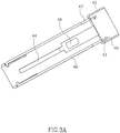
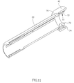
- FIGs. 1A and 1B illustrate a needle protector device 10 for use with a hypodermic needle assembly 12, constructed and operative in accordance with an embodiment of the present invention.
- Hypodermic needle assembly 12 may comprise a syringe 14 in which is slidingly fitted a plunger 16.
- Plunger 16 comprises a distal elastomeric pusher 18 ( Fig. 1B ) and a proximal head 20.
- the distal (outlet) end of syringe 14 may be in fluid communication with a hub portion 22 of a needle 24 comprising a needle tip 26.
- the entire hypodermic needle assembly 12 and needle protector device 10 may be molded or otherwise constructed of a medically-approved plastic and provided to the end-user, e.g., the medical practitioner, in a sealed package (not shown), so that the assembly and device are in a completely sterile condition when removed from the package.
- hypodermic needle assembly 12 is disposed inside needle protector device 10.
- Needle protector device 10 may comprise a protector tube 30, such as an inner hollow tube configured to slide over syringe 14.
- Protector tube 30 may be slidingly disposed in an outer hollow tube 40.
- protector tube 30 comprise one or more abutments in the form of resilient tongues 34 at a proximal end thereof, which may be formed with outwardly chamfered proxirnal ends 36.
- Resilient tongues 34 tend to spring radially outwards from the outer contour of protecfor tube 30.
- Protector tube 30 may be formed with an elongate axial groove 32 and a depression 38 formed proximal to groove 32. Depression 38 may be axially aligned with groove 32.
- Axial groove 32 and depression 38 may be formed through the thickness of the wall of protector tube 30.
- Groove 32 may be formed with a chamfered, proximal ramp 37.
- outer tube 40 comprises a proximal enlarged end 42, in which a proximal hub 17 of syringe 14 may be received (as seen in Fig. 1 ).
- Outer tube 40 may be formed with an elongate axial groove 44 and a depression 46 formed proximal to groove 44. Depression 46 may be axially aligned with groove 44. Axial groove 44 and depression 46 may be formed through the thickness of the wall of outer tube 40.
- One or more resilient tongues 48 may be formed at a distal end of outer tube 40, which may be formed with inwardly facing lugs 49.
- One or more channels 47 may be formed at a proximal end of outer tube 40 distally of enlarged end 42.
- enlarged end 42 may comprise a plurality of inner, radially spaced, resilient retaining members 43, which may be formed with inwardly chamfered proximal ends 45.
- the proximal hub 17 of syringe 14 may be fixedly received and held by retaining members 43.
- a biasing device 50 such as but not limited to, a coil spring, is disposed inside outer tube 40 and provide an urging force on a proximal end of protector tube 30, which forces tends to urge protector tube 30 distally towards the needle end of hypodermic needle assembly 12.
- a biasing device 50 such as but not limited to, a coil spring
- the proximal end 36 of tongue 34 is initially fixedly received in depression 46 of outer tube 40. In this position, protector tube 30 is prevented from being urge distally along syringe 14. It may be seen in Fig. 1A and Fig. 4 that lugs 49 are initially received in axial groove 32.
- a release mechanism 52 is disposed in outer tube 40.
- Release mechanism 52 shown in detail in Fig. 5 to which reference is now made, comprises a ring 53 with proximally extending syringe interface members 54 and distally extending fingers 55. Fingers 55 may comprise bent ends 56, which may serve as chamfered surfaces to better push against ends 36 of tongues 34 of protector tube 30, as is described below. As seen in Fig. 4 , syringe interface members 54 sit in grooves of the shaft of plunger 16, and fingers 55 do initially not abut tongues 34 of protector tube 30. Release mechanism 52 may be made of any suitably sturdy material, such as but not limited to, stainless steel.
- Plunger 16 may be pushed distally in the direction of an arrow 58 to inject fluid (not shown) from syringe 14 through needle 24.
- head 20 of plunger 16 contacts and distally pushes syringe interface members 54 of release mechanism 52.
- This causes bent ends 56 ( Fig. 5 ) of fingers 55 to slide over ends 36 of tongues 34 of protector tube 30, thereby radially pushing tongues 34 inwards and out of engagement with depressions 46 of outer tube 40.
- channels 47 may permit unobstructed distal movement of release mechanism 52 with respect to outer tube 40.
- protector tube 30 has moved distally towards covering needle tip 26, and is illustrated at a position where it may be stopped by the skin of a patient (not shown).
- Axial groove 32 has slid distally such that ramp 37 (at the proximal end of axial groove 32) is now adjacent lug 49 of outer tube 40.
- protector tube 30 has continued to be urged distally and now covers needle tip 26.
- Ramp 37 has moved past lug 49 of outer tube 40, and lug 49 is now fixedly received in depression 38 of protector tube 30.
- Distal movement is also prevented by tongue 34 abutting the distal end of groove 44 and the syringe body.
- protector tube 30 protects against accidental or inadvertent pricking by needle tip 26.
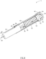
- Needle protector device 60 is similar in construction to needle protector device 10, with like elements being designated by like numerals.
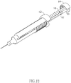
- Needle protector device 60 may comprise an elongate release mechanism 62, shown more in detail in Fig. 10 .
- Release mechanism 62 may comprise a ring 63 with proximally extending syringe interface members 64 and distally extending fingers 65.
- Syringe interface members 64 may extend from relatively long attachment members 66 which extend from ring 63.
- Attachment members 66 may be provided with transverse ears 67 near syringe interface members 64.
- Release mechanism 62 may be made of any suitably sturdy material, such as but not limited to, stainless steel.
- release mechanism 62. and the operation of needle protector device 60 may be similar to that described hereinabove for needle protector device 10. That is, upon distal pushing of plunger 16, head 20 of plunger 16 contacts and distally pushes syringe interface members 64 of release mechanism 62. This may cause fingers 65 to move tongues 34 of protector tube 30 out of engagement with depressions 46 of outer tube 40, thereby permitting biasing device 50 to urge protector tube 30 distally to cover needle tip 26.
- protector tube 30 comprises one or more outer abutments 61 ( Fig. 9 ), which initially are proximal to one or more retaining stubs 69 ( Fig. 11 ) formed in outer tube 40.
- Retaining stubs 69 may be configured to easily yield, break, rupture or shear.
- the trigger release action of this embodiment may be as follows. Upon distal pushing of plunger 16, head 20 of plunger 16 contacts and distally pushes syringe interface members 64 of release mechanism 62.
- biasing device 50 may urge protector tube 30 distally to cover needle tip 26.
- the biasing device 50 may not have to be initially in a contracted state. Instead, due to the long attachment members 66, release mechanism 62 contracts biasing device 50 upon distal pushing of plunger head 20, prior to fingers 65 triggering release of protector tube 30. By the time fingers 65 do release protector tube 30, biasing device 50 has sufficiently contracted to store the potential energy necessary for urging and propelling protector tube 30 distally to cover needle tip 26.
- syringe holding device 70 may comprise one or more resilient dogs 72 that face the proximal end of enlarged end 42, and chamfered protrusions 74 protruding from enlarged end 42, whose chamfered edges also faces the proximal end of enlarged end 42.
- the proximal hub 17 of syringe 14 ( Fig. 9 ) may fit snugly in a notch 76 ( Fig. 11 ) formed in resilient dogs 72.
- a plunger head holding device 80 may be provided.
- Plunger head holding device 80 may comprise one or more chamfered lugs 82 formed with a groove 83 in which the head 20 of plunger 16 may be fixedly received, such as by snap fit.
- a cap member 84 may distally extend from the outer periphery of lugs 82 and terminate in a plurality of catches 85 that face radially inwards. As seen in Fig. 12 , after plunger head 20 has been pushed distally towards proximal hub 17 of syringe 14, catches 85 hook together with dogs 72.
- transverse ears 67 may snappingly lock on to chamfered protrusions 74 of enlarged end 42 so as to arrest movement of release mechanism 62 and thus reliably prevent inadvertent movement of protector tube 30 after removal of the needle from the patient's skin.
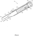
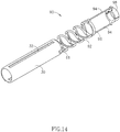
- Needle protector device 90 may comprise a biasing device 92 which is an integral extension of protector tube 30.
- Biasing device 92 may comprise a spiral spring molded of plastic together with protector tube 30.
- One or more proximally extending arms 94 may extend from an end ring 96 of biasing device 92.
- a clamping ring 98 may be attached to the proximal end of arms 94, and may be used to clamp on head 20 of syringe 14 (not shown in Fig. 14 ).
- the trigger mechanism that releases protector tube 30 and permits biasing device 92 to urge protector tube 30 distally to cover needle tip 26 may be similar to that described hereinabove for the embodiment illustrated in Fig. 9 and 11 . That is, the outer abutments 61 of protector tube 30 may be initially proximal to retaining stubs 69 ( Fig. 11 ) formed in outer tube 40. Upon distal pushing of plunger 16, outer abutments 61 push against and eventually shear retaining stubs 69. Once retaining stubs 69 are sheared, biasing device 92 may urge protector tube 30 distally to cover needle tip 26.
- biasing device 92 may not have to be initially in a contracted state. Instead, by the time outer abutments 61 shear retaining stubs 69, biasing device 92 has sufficiently contracted to store the potential energy necessary for urging and propelling protector tube 30 distally to cover needle tip 26.
Landscapes
- Health & Medical Sciences (AREA)
- Engineering & Computer Science (AREA)
- Heart & Thoracic Surgery (AREA)
- Vascular Medicine (AREA)
- Anesthesiology (AREA)
- Biomedical Technology (AREA)
- Environmental & Geological Engineering (AREA)
- Hematology (AREA)
- Life Sciences & Earth Sciences (AREA)
- Animal Behavior & Ethology (AREA)
- General Health & Medical Sciences (AREA)
- Public Health (AREA)
- Veterinary Medicine (AREA)
- Infusion, Injection, And Reservoir Apparatuses (AREA)
Claims (8)
- Nadelschutzvorrichtung (10), umfassend:ein Schutzrohr (30), das gleitend in einem Außenrohr (40) angeordnet ist und gleitend über eine eine Nadel (24) umfassende Spritze (14) angeordnet ist, wobei das Schutzrohr (30) mindestens einen Anschlag (34) umfasst, der anfänglich mit dem Außenrohr (40) so in Eingriff steht, dass das Schutzrohr (30) am Bewegen in distaler Richtung bezüglich der Spritze (14) gehindert ist, wobei das Außenrohr (40) ein proximal vergrößertes Ende (42) umfasst, in welches eine proximale Nabe der Spritze aufgenommen ist;eine im Innern des Außenrohrs (40) angeordnete Vorspannungsvorrichtung (50), die so funktioniert, dass sie eine Treibkraft an dem Schutzrohr (30) in einer Richtung bereitstellt, die dazu neigt, das Schutzrohr (30) distal in Richtung einer Spitze (26) der Nadel (24) zu treiben; und einen Freigabemechanismus (52), der so funktioniert, dass er den mindestens einen Anschlag (34) aus dem Eingriff mit dem Außenrohr (40) bei distalem Schieben eines Kolbens (16) der Spritze (14) herausbewegt, so dass, wenn der mindestens eine Anschlag (34) außer Eingriff mit dem Außenrohr (40) ist, die Vorspannvorrichtung (50) das Schutzrohr (30) distal in Richtung der Spitze (26) der Nadel (24) treibt;wobei der mindestens eine Anschlag (34) mindestens eine federnde Zunge (34) umfasst, die dazu neigt, radial nach außen von einer Außenkontur des Schutzrohrs (30) zu federn, dadurch gekennzeichnet, dass der Freigabemechanismus (52) im Außenrohr (40) angeordnet ist und einen Ring (53) mit sich in proximaler Richtung erstreckenden Spritzenschnittstellenelementen (54), die in Nuten eines Schaftes des Kolbens (16) sitzen, und sich in distaler Richtung erstreckende Finger (55), wobei jeder gestaltet, um anfänglich nicht an einer jeweiligen Zunge (34) anstoßen, umfasst, wobei der Freigabemechanismus so gestaltet ist, dass beim distalen Schieben des Kolbens (16) der Kopf (20) des Kolbens (16) die Spritzenschnittstellenelemente (54) berührt und in distaler Richtung schiebt, was dazu führt, dass die sich in distaler Richtung erstreckenden Finger (55) gegen ein Ende der jeweiligen mindestens einen federnden Zunge (34) schieben, wodurch sie die mindestens eine federnde Zunge (34) radial nach innen und außer Eingriff mit dem Außenrohr (40) schieben.
- Nadelschutzvorrichtung nach Anspruch 1, wobei das Schutzrohr mit einer langgestreckten axialen Nut und einer proximal zur Nut gebildeten Vertiefung gebildet ist, und das Außenrohr mit einer langgestreckten axialen Nut und einer proximal zur Nut gebildeten Vertiefung, und mindestens einer federnden, an einem distalen Ende davon, das Ansätze umfasst, gebildeten Zunge gebildet ist, wobei ein proximales Ende der mindestens einen federnden Zunge des Schutzrohrs anfänglich in der Vertiefung des Außenrohrs fest aufgenommen ist, und die Ansätze anfänglich in der axialen Nut des Schutzrohrs aufgenommen sind.
- Nadelschutzvorrichtung (10) nach Anspruch 2, wobei die Vertiefung (38) des Schutzrohrs (30) axial mit der Nut (32) des Schutzrohrs ausgerichtet ist.
- Nadelschutzvorrichtung (10) nach Anspruch 2, wobei die axiale Nut (32) und die Vertiefung (38) des Schutzrohrs (30) mittels einer Wanddicke des Schutzrohrs (30) gebildet sind.
- Nadelschutzvorrichtung (10) nach Anspruch 2, wobei die axiale Nut (32) des Schutzrohrs (30) mit einer abgeschrägten, proximalen Rampe (37) gebildet ist.
- Nadelschutzvorrichtung (10) nach Anspruch 2, wobei die Vertiefung (38) des Außenrohrs (40) axial mit der Nut (44) des Außenrohrs (40) ausgerichtet ist.
- Nadelschutzvorrichtung (10) nach Anspruch 2, wobei die axiale Nut (32) und die Vertiefung (38) des Außenrohrs (40) mittels einer Wanddicke des Außenrohrs (40) gebildet sind.
- Nadelschutzvorrichtung (10) nach einem der vorhergehenden Ansprüche, ferner gekennzeichnet durch ein Kappenelement (84), das darin einen Kopf (20) des Kolbens (16) der Spritze (14) aufnimmt, wobei das Kappenelement (84) angeordnet ist, um auf einem Teil des Außenrohrs (40) nach ausreichendem distalen Schieben des Kolbens (16) der Spritze (14) einzurasten, um eine Bewegung des Kolbens (16) zu arretieren.
Applications Claiming Priority (3)
| Application Number | Priority Date | Filing Date | Title |
|---|---|---|---|
| US334071 | 1989-04-06 | ||
| US10/334,071 US6846302B2 (en) | 2002-12-31 | 2002-12-31 | Needle protector device |
| PCT/IL2003/001099 WO2004058338A1 (en) | 2002-12-31 | 2003-12-23 | Needle protector device |
Publications (2)
| Publication Number | Publication Date |
|---|---|
| EP1578462A1 EP1578462A1 (de) | 2005-09-28 |
| EP1578462B1 true EP1578462B1 (de) | 2018-03-07 |
Family
ID=32654918
Family Applications (1)
| Application Number | Title | Priority Date | Filing Date |
|---|---|---|---|
| EP03780587.6A Expired - Lifetime EP1578462B1 (de) | 2002-12-31 | 2003-12-23 | Nadelschutzvorrichtung |
Country Status (4)
| Country | Link |
|---|---|
| US (1) | US6846302B2 (de) |
| EP (1) | EP1578462B1 (de) |
| AU (1) | AU2003288512A1 (de) |
| WO (1) | WO2004058338A1 (de) |
Families Citing this family (83)
| Publication number | Priority date | Publication date | Assignee | Title |
|---|---|---|---|---|
| US11083841B2 (en) | 2002-08-09 | 2021-08-10 | Fenwal, Inc. | Needle protector, needle assembly and fluid processing set including the same |
| WO2004069302A2 (en) * | 2003-01-30 | 2004-08-19 | Becton, Dickinson And Company | Holder with safety shield for a drug delivery device |
| US7449012B2 (en) * | 2004-08-06 | 2008-11-11 | Meridian Medical Technologies, Inc. | Automatic injector |
| US8048035B2 (en) * | 2004-08-06 | 2011-11-01 | Meridian Medical Technologies, Inc. | Automatic injector with needle cover |
| FR2884723B1 (fr) | 2005-04-20 | 2008-03-14 | Becton Dickinson France Soc Pa | Dispositif de protection d'un dispositif d'injection |
| US8372044B2 (en) * | 2005-05-20 | 2013-02-12 | Safety Syringes, Inc. | Syringe with needle guard injection device |
| GB0600212D0 (en) * | 2006-01-06 | 2006-02-15 | Liversidge Barry P | Medical needle safety device |
| US7856751B1 (en) * | 2007-01-23 | 2010-12-28 | Alien Products, Incorporated | Dual purpose fishing tool |
| CA2679968C (en) | 2007-03-07 | 2013-07-02 | Becton, Dickinson And Company | Safety blood collection assembly with indicator |
| US8888713B2 (en) | 2007-03-07 | 2014-11-18 | Becton, Dickinson And Company | Safety blood collection assembly with indicator |
| US10420880B2 (en) | 2007-10-02 | 2019-09-24 | West Pharma. Services IL, Ltd. | Key for securing components of a drug delivery system during assembly and/or transport and methods of using same |
| US7967795B1 (en) | 2010-01-19 | 2011-06-28 | Lamodel Ltd. | Cartridge interface assembly with driving plunger |
| WO2009044401A2 (en) * | 2007-10-02 | 2009-04-09 | Yossi Gross | External drug pump |
| US9656019B2 (en) | 2007-10-02 | 2017-05-23 | Medimop Medical Projects Ltd. | Apparatuses for securing components of a drug delivery system during transport and methods of using same |
| US9345836B2 (en) | 2007-10-02 | 2016-05-24 | Medimop Medical Projects Ltd. | Disengagement resistant telescoping assembly and unidirectional method of assembly for such |
| FR2922112B1 (fr) * | 2007-10-11 | 2009-12-04 | Rexam Pharma La Verpilliere | Dispositif de securite pour une seringue d'injection de liquide et ensemble a seringue comprenant ce dispositif |
| USD596290S1 (en) * | 2007-12-25 | 2009-07-14 | Daikyo Seiko, Ltd. | Syringe barrel body cover |
| US8814337B2 (en) * | 2007-12-27 | 2014-08-26 | Eastman Kodak Company | Inkjet ink sets for high speed printing on plain papers and glossy media |
| US8356892B2 (en) * | 2007-12-27 | 2013-01-22 | Eastman Kodak Company | Inkjet inks for printing on both plain and photo-glossy papers |
| US8323251B2 (en) | 2008-01-14 | 2012-12-04 | Fenwal, Inc. | Phlebotomy needle assembly and frangible cover |
| US8721603B2 (en) | 2008-01-15 | 2014-05-13 | West Pharmaceutical Services, Inc. | Syringe with co-molded hub and cannula |
| CN101896214B (zh) * | 2008-01-15 | 2013-05-29 | 西部制药服务公司 | 将插管模制到注射器针筒上的筒夹机构和方法 |
| US8603009B2 (en) | 2008-03-07 | 2013-12-10 | Becton, Dickinson And Company | Flashback blood collection needle |
| US8795198B2 (en) | 2008-03-07 | 2014-08-05 | Becton, Dickinson And Company | Flashback blood collection needle |
| US7676982B1 (en) * | 2008-03-19 | 2010-03-16 | San Fu Lee | Method and apparatus for venting fish |
| EP2110149B1 (de) * | 2008-03-28 | 2017-05-03 | Fenwal, Inc. | Flügelnadelanordnung und zerbrechliche Hülle |
| US7934336B2 (en) * | 2008-07-03 | 2011-05-03 | Cooksey Thomas C | Fish pressure equilibrating tool |
| EP2143456B1 (de) * | 2008-07-08 | 2011-08-03 | Kunststofftechnik Waidhofen an der Thaya GmbH | Kanülenschutz und Einwegspritzensystem |
| US9393369B2 (en) | 2008-09-15 | 2016-07-19 | Medimop Medical Projects Ltd. | Stabilized pen injector |
| US12097357B2 (en) | 2008-09-15 | 2024-09-24 | West Pharma. Services IL, Ltd. | Stabilized pen injector |
| US20100145305A1 (en) * | 2008-11-10 | 2010-06-10 | Ruth Alon | Low volume accurate injector |
| EP2201975A1 (de) * | 2008-12-23 | 2010-06-30 | Sanofi-Aventis Deutschland GmbH | Vorrichtung zur Verabreichung von Medikamenten |
| US8152779B2 (en) * | 2008-12-30 | 2012-04-10 | Medimop Medical Projects Ltd. | Needle assembly for drug pump |
| CA2753812C (en) | 2009-03-13 | 2015-07-21 | Eli Lilly And Company | Apparatus for injecting a pharmaceutical with automatic syringe retraction following injection |
| US8864725B2 (en) | 2009-03-17 | 2014-10-21 | Baxter Corporation Englewood | Hazardous drug handling system, apparatus and method |
| US9526846B2 (en) | 2009-08-19 | 2016-12-27 | Safety Syringes, Inc. | Patient-contact activated needle stick safety device |
| US8337468B1 (en) | 2009-08-26 | 2012-12-25 | Tonya Reis | Needlestick injury prevention device |
| US10071198B2 (en) | 2012-11-02 | 2018-09-11 | West Pharma. Servicees IL, Ltd. | Adhesive structure for medical device |
| US10071196B2 (en) | 2012-05-15 | 2018-09-11 | West Pharma. Services IL, Ltd. | Method for selectively powering a battery-operated drug-delivery device and device therefor |
| US8157769B2 (en) | 2009-09-15 | 2012-04-17 | Medimop Medical Projects Ltd. | Cartridge insertion assembly for drug delivery system |
| US8348898B2 (en) | 2010-01-19 | 2013-01-08 | Medimop Medical Projects Ltd. | Automatic needle for drug pump |
| GB2478349A (en) | 2010-03-05 | 2011-09-07 | Owen Mumford Ltd | Injection device having projections reducing the diameter of the syringe passage |
| GB201004102D0 (en) * | 2010-03-12 | 2010-04-28 | Liversidge Barry P | Syringe barrels and handling systems |
| EP2569031B1 (de) | 2010-05-10 | 2017-10-11 | Medimop Medical Projects Ltd. | Genauer injektor für geringe volumen |
| KR101204565B1 (ko) | 2010-09-03 | 2012-11-23 | 강진희 | 주사기용 삽입장치 |
| WO2012055839A2 (en) * | 2010-10-25 | 2012-05-03 | Sanofi-Aventis Deutschland Gmbh | Safety devices |
| CN103328038A (zh) * | 2010-12-01 | 2013-09-25 | 史拜诺莫度雷森公司 | 向神经解剖结构直接递送药剂 |
| WO2012093069A1 (en) * | 2011-01-04 | 2012-07-12 | Sanofi-Aventis Deutschland Gmbh | Adaptor means for use in combination with a pre-filled syringe and a safety device, safety device and injection device |
| USD702834S1 (en) | 2011-03-22 | 2014-04-15 | Medimop Medical Projects Ltd. | Cartridge for use in injection device |
| USD693002S1 (en) | 2011-09-21 | 2013-11-05 | West Pharmaceutical Services, Inc. | Hub for medical container |
| EP2578256A1 (de) * | 2011-10-06 | 2013-04-10 | Sanofi-Aventis Deutschland GmbH | Nadelsicherheitsvorrichtung |
| MX366271B (es) | 2011-11-07 | 2019-07-04 | Safety Syringes Inc | Guarda de aguja para liberacion de activador de contacto. |
| US9072827B2 (en) | 2012-03-26 | 2015-07-07 | Medimop Medical Projects Ltd. | Fail safe point protector for needle safety flap |
| USD689188S1 (en) | 2012-07-19 | 2013-09-03 | West Pharmaceutical Services, Inc. | Syringe plunger rod |
| EP2722066A1 (de) * | 2012-10-16 | 2014-04-23 | Sanofi-Aventis Deutschland GmbH | Medikamentenbehälterträger |
| US9421323B2 (en) | 2013-01-03 | 2016-08-23 | Medimop Medical Projects Ltd. | Door and doorstop for portable one use drug delivery apparatus |
| US9011164B2 (en) | 2013-04-30 | 2015-04-21 | Medimop Medical Projects Ltd. | Clip contact for easy installation of printed circuit board PCB |
| USD765838S1 (en) | 2015-03-26 | 2016-09-06 | Tech Group Europe Limited | Syringe retention clip |
| US10293120B2 (en) | 2015-04-10 | 2019-05-21 | West Pharma. Services IL, Ltd. | Redundant injection device status indication |
| US10149943B2 (en) | 2015-05-29 | 2018-12-11 | West Pharma. Services IL, Ltd. | Linear rotation stabilizer for a telescoping syringe stopper driverdriving assembly |
| TW201703802A (zh) * | 2015-06-03 | 2017-02-01 | 賽諾菲阿凡提斯德意志有限公司 | 注射器支架及自動注射器(一) |
| TW201707738A (zh) * | 2015-06-03 | 2017-03-01 | 賽諾菲阿凡提斯德意志有限公司 | 注射器支架及自動注射器(二) |
| US11207465B2 (en) | 2015-06-04 | 2021-12-28 | West Pharma. Services Il. Ltd. | Cartridge insertion for drug delivery device |
| US9987432B2 (en) | 2015-09-22 | 2018-06-05 | West Pharma. Services IL, Ltd. | Rotation resistant friction adapter for plunger driver of drug delivery device |
| US10086145B2 (en) | 2015-09-22 | 2018-10-02 | West Pharma Services Il, Ltd. | Rotation resistant friction adapter for plunger driver of drug delivery device |
| US10576207B2 (en) | 2015-10-09 | 2020-03-03 | West Pharma. Services IL, Ltd. | Angled syringe patch injector |
| JP7044708B2 (ja) | 2015-10-09 | 2022-03-30 | ウェスト ファーマ サービシーズ イスラエル リミテッド | カスタマイズシリンジの充填方法 |
| CN113041432B (zh) | 2016-01-21 | 2023-04-07 | 西医药服务以色列有限公司 | 包括视觉指示物的药剂输送装置 |
| US10646643B2 (en) | 2016-01-21 | 2020-05-12 | West Pharma. Services IL, Ltd. | Needle insertion and retraction mechanism |
| CN111544704B (zh) | 2016-01-21 | 2022-06-03 | 西医药服务以色列有限公司 | 自动注射器中的力牵制 |
| WO2017161076A1 (en) | 2016-03-16 | 2017-09-21 | Medimop Medical Projects Ltd. | Staged telescopic screw assembly having different visual indicators |
| US10376647B2 (en) | 2016-03-18 | 2019-08-13 | West Pharma. Services IL, Ltd. | Anti-rotation mechanism for telescopic screw assembly |
| JP6957525B2 (ja) | 2016-06-02 | 2021-11-02 | ウェスト ファーマ サービシーズ イスラエル リミテッド | 3つの位置による針の退避 |
| JP6869327B2 (ja) | 2016-08-01 | 2021-05-12 | ウェスト ファーマ サービシーズ イスラエル リミテッド | 回転防止カートリッジ |
| WO2018026385A1 (en) | 2016-08-01 | 2018-02-08 | Medimop Medical Projects Ltd. | Partial door closure prevention spring |
| CN113855913A (zh) | 2017-05-30 | 2021-12-31 | 西部制药服务有限公司(以色列) | 用于穿戴式注射器的模块化驱动机构 |
| JP7402799B2 (ja) | 2017-12-22 | 2023-12-21 | ウェスト ファーマ サービシーズ イスラエル リミテッド | サイズの異なるカートリッジを利用可能な注射器 |
| LT3801694T (lt) | 2018-06-08 | 2025-12-10 | Antares Pharma, Inc. | Automatinio įterpimo injektorius |
| CA3150005A1 (en) * | 2019-09-17 | 2021-03-25 | Becton Dickinson Holdings Pte. Ltd. | PASSIVE SAFETY DEVICE, INJECTION DEVICE COMPRISING IT, AND METHOD FOR MANUFACTURING SUCH INJECTION DEVICE |
| WO2023066684A1 (en) * | 2021-10-21 | 2023-04-27 | Shl Medical Ag | Delivery member cover |
| WO2023155067A1 (zh) * | 2022-02-16 | 2023-08-24 | 王济扬 | 一种疫苗针的安全针套 |
| USD1109322S1 (en) | 2023-10-02 | 2026-01-13 | Regeneron Pharmaceuticals, Inc. | Drug-delivery device |
| USD1108627S1 (en) | 2023-10-02 | 2026-01-06 | Regeneron Pharmaceuticals, Inc. | Drug-delivery device |
Family Cites Families (11)
| Publication number | Priority date | Publication date | Assignee | Title |
|---|---|---|---|---|
| AU3245393A (en) * | 1991-12-09 | 1993-07-19 | Square One Medical | Rotary lock for needle sheaths |
| US5201720A (en) * | 1992-04-21 | 1993-04-13 | Joseph Borgia | Syringe holding and ejecting assembly |
| GB9212742D0 (en) * | 1992-06-16 | 1992-07-29 | Sterimatic Holdings Ltd | Syringe or blood collection system |
| FR2770405B1 (fr) * | 1997-10-30 | 1999-12-10 | Aguettant Lab | Seringue de securite a usage medical |
| US6319233B1 (en) * | 1998-04-17 | 2001-11-20 | Becton, Dickinson And Company | Safety shield system for prefilled syringes |
| US6679864B2 (en) * | 1998-04-17 | 2004-01-20 | Becton Dickinson And Company | Safety shield system for prefilled syringes |
| US6030366A (en) * | 1998-11-09 | 2000-02-29 | Safety Syringes, Inc. | Syringe guard system for a unit dose syringe |
| FR2801795B1 (fr) * | 1999-12-07 | 2002-07-05 | Plastef Investissements | Dispositif de support de securite pour une seringue et ensemble d'un tel dispositif et d'une seringue |
| GB0003790D0 (en) * | 2000-02-18 | 2000-04-05 | Astrazeneca Uk Ltd | Medical device |
| WO2001080931A2 (en) * | 2000-04-21 | 2001-11-01 | Eli Lilly And Company | Safety device for a syringe |
| US6613022B1 (en) * | 2000-05-05 | 2003-09-02 | Safety Syringes, Inc. | Passive needle guard for syringes |
-
2002
- 2002-12-31 US US10/334,071 patent/US6846302B2/en not_active Expired - Lifetime
-
2003
- 2003-12-23 EP EP03780587.6A patent/EP1578462B1/de not_active Expired - Lifetime
- 2003-12-23 AU AU2003288512A patent/AU2003288512A1/en not_active Abandoned
- 2003-12-23 WO PCT/IL2003/001099 patent/WO2004058338A1/en not_active Ceased
Also Published As
| Publication number | Publication date |
|---|---|
| US20040127857A1 (en) | 2004-07-01 |
| EP1578462A1 (de) | 2005-09-28 |
| US6846302B2 (en) | 2005-01-25 |
| AU2003288512A1 (en) | 2004-07-22 |
| WO2004058338A1 (en) | 2004-07-15 |
Similar Documents
| Publication | Publication Date | Title |
|---|---|---|
| EP1578462B1 (de) | Nadelschutzvorrichtung | |
| JP3946324B2 (ja) | ロック可能な安全遮蔽体を有する医用注入装置 | |
| CN101594899B (zh) | 具有封锁住的保护位置的针保护装置 | |
| US8357125B2 (en) | Autoinjector with deactivating means moveable by a safety shield | |
| JP4644185B2 (ja) | 薬物送達装置用の安全シールド付き保持器 | |
| JP4699192B2 (ja) | 注射器用自動作動式安全シールドシステム | |
| EP1946789B1 (de) | Sicherheitsschirmsystem für vorgefüllte Spritzen | |
| EP1694389B1 (de) | Sicherheitsvorrichtung für eine spritze | |
| JP3370948B2 (ja) | 医療装置及びその遮蔽体装置 | |
| US6485469B1 (en) | Shielded dental safety needle | |
| ES2795977T3 (es) | Inyector de seguridad con botón pulsador | |
| US20100137810A1 (en) | Safety guards for syringe needle | |
| EP0307367A2 (de) | Selbstblockierende Hypodermische Spritze zum Einmalgebrauch mit Nadel-Schutzkappe | |
| CN111712287A (zh) | 用于注射组合物的设置有安全针盖的医疗装置 | |
| US6945958B2 (en) | Safety needle apparatus | |
| EP4233939A2 (de) | Sicherheitsnadelvorrichtung | |
| CN219050059U (zh) | 带有防针刺功能的药剂输送装置 | |
| US5352208A (en) | Safe non-reusable hypodermic syringe | |
| CN111712288A (zh) | 用于支承填充有药物组分的医疗容器的医疗注射装置 | |
| TR2023002933T2 (tr) | Önceden doldurulmuş şiringa ve enjeksi̇yon ci̇hazi i̇çi̇n emni̇yet ci̇hazi |
Legal Events
| Date | Code | Title | Description |
|---|---|---|---|
| PUAI | Public reference made under article 153(3) epc to a published international application that has entered the european phase |
Free format text: ORIGINAL CODE: 0009012 |
|
| 17P | Request for examination filed |
Effective date: 20050718 |
|
| AK | Designated contracting states |
Kind code of ref document: A1 Designated state(s): AT BE BG CH CY CZ DE DK EE ES FI FR GB GR HU IE IT LI LU MC NL PT RO SE SI SK TR |
|
| AX | Request for extension of the european patent |
Extension state: AL LT LV MK |
|
| DAX | Request for extension of the european patent (deleted) | ||
| 17Q | First examination report despatched |
Effective date: 20150710 |
|
| GRAP | Despatch of communication of intention to grant a patent |
Free format text: ORIGINAL CODE: EPIDOSNIGR1 |
|
| RIC1 | Information provided on ipc code assigned before grant |
Ipc: A61M 5/50 20060101ALN20170906BHEP Ipc: A61M 5/32 20060101AFI20170906BHEP |
|
| INTG | Intention to grant announced |
Effective date: 20171005 |
|
| GRAS | Grant fee paid |
Free format text: ORIGINAL CODE: EPIDOSNIGR3 |
|
| GRAA | (expected) grant |
Free format text: ORIGINAL CODE: 0009210 |
|
| AK | Designated contracting states |
Kind code of ref document: B1 Designated state(s): AT BE BG CH CY CZ DE DK EE ES FI FR GB GR HU IE IT LI LU MC NL PT RO SE SI SK TR |
|
| REG | Reference to a national code |
Ref country code: GB Ref legal event code: FG4D |
|
| REG | Reference to a national code |
Ref country code: CH Ref legal event code: EP Ref country code: AT Ref legal event code: REF Ref document number: 975884 Country of ref document: AT Kind code of ref document: T Effective date: 20180315 |
|
| REG | Reference to a national code |
Ref country code: DE Ref legal event code: R096 Ref document number: 60351028 Country of ref document: DE |
|
| REG | Reference to a national code |
Ref country code: IE Ref legal event code: FG4D |
|
| REG | Reference to a national code |
Ref country code: NL Ref legal event code: MP Effective date: 20180307 |
|
| PG25 | Lapsed in a contracting state [announced via postgrant information from national office to epo] |
Ref country code: ES Free format text: LAPSE BECAUSE OF FAILURE TO SUBMIT A TRANSLATION OF THE DESCRIPTION OR TO PAY THE FEE WITHIN THE PRESCRIBED TIME-LIMIT Effective date: 20180307 Ref country code: CY Free format text: LAPSE BECAUSE OF FAILURE TO SUBMIT A TRANSLATION OF THE DESCRIPTION OR TO PAY THE FEE WITHIN THE PRESCRIBED TIME-LIMIT Effective date: 20180307 Ref country code: FI Free format text: LAPSE BECAUSE OF FAILURE TO SUBMIT A TRANSLATION OF THE DESCRIPTION OR TO PAY THE FEE WITHIN THE PRESCRIBED TIME-LIMIT Effective date: 20180307 |
|
| REG | Reference to a national code |
Ref country code: AT Ref legal event code: MK05 Ref document number: 975884 Country of ref document: AT Kind code of ref document: T Effective date: 20180307 |
|
| PG25 | Lapsed in a contracting state [announced via postgrant information from national office to epo] |
Ref country code: SE Free format text: LAPSE BECAUSE OF FAILURE TO SUBMIT A TRANSLATION OF THE DESCRIPTION OR TO PAY THE FEE WITHIN THE PRESCRIBED TIME-LIMIT Effective date: 20180307 Ref country code: BG Free format text: LAPSE BECAUSE OF FAILURE TO SUBMIT A TRANSLATION OF THE DESCRIPTION OR TO PAY THE FEE WITHIN THE PRESCRIBED TIME-LIMIT Effective date: 20180607 Ref country code: GR Free format text: LAPSE BECAUSE OF FAILURE TO SUBMIT A TRANSLATION OF THE DESCRIPTION OR TO PAY THE FEE WITHIN THE PRESCRIBED TIME-LIMIT Effective date: 20180608 |
|
| PG25 | Lapsed in a contracting state [announced via postgrant information from national office to epo] |
Ref country code: IT Free format text: LAPSE BECAUSE OF FAILURE TO SUBMIT A TRANSLATION OF THE DESCRIPTION OR TO PAY THE FEE WITHIN THE PRESCRIBED TIME-LIMIT Effective date: 20180307 Ref country code: RO Free format text: LAPSE BECAUSE OF FAILURE TO SUBMIT A TRANSLATION OF THE DESCRIPTION OR TO PAY THE FEE WITHIN THE PRESCRIBED TIME-LIMIT Effective date: 20180307 Ref country code: NL Free format text: LAPSE BECAUSE OF FAILURE TO SUBMIT A TRANSLATION OF THE DESCRIPTION OR TO PAY THE FEE WITHIN THE PRESCRIBED TIME-LIMIT Effective date: 20180307 Ref country code: EE Free format text: LAPSE BECAUSE OF FAILURE TO SUBMIT A TRANSLATION OF THE DESCRIPTION OR TO PAY THE FEE WITHIN THE PRESCRIBED TIME-LIMIT Effective date: 20180307 |
|
| PG25 | Lapsed in a contracting state [announced via postgrant information from national office to epo] |
Ref country code: AT Free format text: LAPSE BECAUSE OF FAILURE TO SUBMIT A TRANSLATION OF THE DESCRIPTION OR TO PAY THE FEE WITHIN THE PRESCRIBED TIME-LIMIT Effective date: 20180307 Ref country code: SK Free format text: LAPSE BECAUSE OF FAILURE TO SUBMIT A TRANSLATION OF THE DESCRIPTION OR TO PAY THE FEE WITHIN THE PRESCRIBED TIME-LIMIT Effective date: 20180307 Ref country code: CZ Free format text: LAPSE BECAUSE OF FAILURE TO SUBMIT A TRANSLATION OF THE DESCRIPTION OR TO PAY THE FEE WITHIN THE PRESCRIBED TIME-LIMIT Effective date: 20180307 |
|
| REG | Reference to a national code |
Ref country code: DE Ref legal event code: R097 Ref document number: 60351028 Country of ref document: DE |
|
| PG25 | Lapsed in a contracting state [announced via postgrant information from national office to epo] |
Ref country code: PT Free format text: LAPSE BECAUSE OF FAILURE TO SUBMIT A TRANSLATION OF THE DESCRIPTION OR TO PAY THE FEE WITHIN THE PRESCRIBED TIME-LIMIT Effective date: 20180709 |
|
| PLBE | No opposition filed within time limit |
Free format text: ORIGINAL CODE: 0009261 |
|
| STAA | Information on the status of an ep patent application or granted ep patent |
Free format text: STATUS: NO OPPOSITION FILED WITHIN TIME LIMIT |
|
| PG25 | Lapsed in a contracting state [announced via postgrant information from national office to epo] |
Ref country code: DK Free format text: LAPSE BECAUSE OF FAILURE TO SUBMIT A TRANSLATION OF THE DESCRIPTION OR TO PAY THE FEE WITHIN THE PRESCRIBED TIME-LIMIT Effective date: 20180307 |
|
| PGFP | Annual fee paid to national office [announced via postgrant information from national office to epo] |
Ref country code: DE Payment date: 20181210 Year of fee payment: 16 |
|
| 26N | No opposition filed |
Effective date: 20181210 |
|
| PG25 | Lapsed in a contracting state [announced via postgrant information from national office to epo] |
Ref country code: SI Free format text: LAPSE BECAUSE OF FAILURE TO SUBMIT A TRANSLATION OF THE DESCRIPTION OR TO PAY THE FEE WITHIN THE PRESCRIBED TIME-LIMIT Effective date: 20180307 |
|
| PGFP | Annual fee paid to national office [announced via postgrant information from national office to epo] |
Ref country code: FR Payment date: 20181219 Year of fee payment: 16 Ref country code: GB Payment date: 20181218 Year of fee payment: 16 |
|
| REG | Reference to a national code |
Ref country code: CH Ref legal event code: PL |
|
| PG25 | Lapsed in a contracting state [announced via postgrant information from national office to epo] |
Ref country code: LU Free format text: LAPSE BECAUSE OF NON-PAYMENT OF DUE FEES Effective date: 20181223 Ref country code: MC Free format text: LAPSE BECAUSE OF FAILURE TO SUBMIT A TRANSLATION OF THE DESCRIPTION OR TO PAY THE FEE WITHIN THE PRESCRIBED TIME-LIMIT Effective date: 20180307 |
|
| REG | Reference to a national code |
Ref country code: IE Ref legal event code: MM4A |
|
| REG | Reference to a national code |
Ref country code: BE Ref legal event code: MM Effective date: 20181231 |
|
| PG25 | Lapsed in a contracting state [announced via postgrant information from national office to epo] |
Ref country code: IE Free format text: LAPSE BECAUSE OF NON-PAYMENT OF DUE FEES Effective date: 20181223 |
|
| PG25 | Lapsed in a contracting state [announced via postgrant information from national office to epo] |
Ref country code: BE Free format text: LAPSE BECAUSE OF NON-PAYMENT OF DUE FEES Effective date: 20181231 |
|
| PG25 | Lapsed in a contracting state [announced via postgrant information from national office to epo] |
Ref country code: LI Free format text: LAPSE BECAUSE OF NON-PAYMENT OF DUE FEES Effective date: 20181231 Ref country code: CH Free format text: LAPSE BECAUSE OF NON-PAYMENT OF DUE FEES Effective date: 20181231 |
|
| PG25 | Lapsed in a contracting state [announced via postgrant information from national office to epo] |
Ref country code: TR Free format text: LAPSE BECAUSE OF FAILURE TO SUBMIT A TRANSLATION OF THE DESCRIPTION OR TO PAY THE FEE WITHIN THE PRESCRIBED TIME-LIMIT Effective date: 20180307 |
|
| PG25 | Lapsed in a contracting state [announced via postgrant information from national office to epo] |
Ref country code: HU Free format text: LAPSE BECAUSE OF FAILURE TO SUBMIT A TRANSLATION OF THE DESCRIPTION OR TO PAY THE FEE WITHIN THE PRESCRIBED TIME-LIMIT; INVALID AB INITIO Effective date: 20031223 |
|
| REG | Reference to a national code |
Ref country code: DE Ref legal event code: R119 Ref document number: 60351028 Country of ref document: DE |
|
| GBPC | Gb: european patent ceased through non-payment of renewal fee |
Effective date: 20191223 |
|
| PG25 | Lapsed in a contracting state [announced via postgrant information from national office to epo] |
Ref country code: GB Free format text: LAPSE BECAUSE OF NON-PAYMENT OF DUE FEES Effective date: 20191223 Ref country code: FR Free format text: LAPSE BECAUSE OF NON-PAYMENT OF DUE FEES Effective date: 20191231 Ref country code: DE Free format text: LAPSE BECAUSE OF NON-PAYMENT OF DUE FEES Effective date: 20200701 |