EP1577960B1 - Module d'actionneur - Google Patents
Module d'actionneur Download PDFInfo
- Publication number
- EP1577960B1 EP1577960B1 EP04106329A EP04106329A EP1577960B1 EP 1577960 B1 EP1577960 B1 EP 1577960B1 EP 04106329 A EP04106329 A EP 04106329A EP 04106329 A EP04106329 A EP 04106329A EP 1577960 B1 EP1577960 B1 EP 1577960B1
- Authority
- EP
- European Patent Office
- Prior art keywords
- actuator
- sleeve
- centring
- housing
- cover
- Prior art date
- Legal status (The legal status is an assumption and is not a legal conclusion. Google has not performed a legal analysis and makes no representation as to the accuracy of the status listed.)
- Expired - Lifetime
Links
- 229920001971 elastomer Polymers 0.000 claims description 3
- 239000000806 elastomer Substances 0.000 claims description 3
- 230000003993 interaction Effects 0.000 claims description 2
- 239000000446 fuel Substances 0.000 description 8
- 239000000919 ceramic Substances 0.000 description 4
- 238000002485 combustion reaction Methods 0.000 description 3
- 238000002347 injection Methods 0.000 description 3
- 239000007924 injection Substances 0.000 description 3
- 238000005452 bending Methods 0.000 description 2
- 238000005516 engineering process Methods 0.000 description 2
- 238000004519 manufacturing process Methods 0.000 description 2
- 229910001369 Brass Inorganic materials 0.000 description 1
- 239000010951 brass Substances 0.000 description 1
- 230000008602 contraction Effects 0.000 description 1
- 230000001419 dependent effect Effects 0.000 description 1
- 230000017525 heat dissipation Effects 0.000 description 1
- 238000001746 injection moulding Methods 0.000 description 1
- 238000007650 screen-printing Methods 0.000 description 1
Images


Classifications
-
- F—MECHANICAL ENGINEERING; LIGHTING; HEATING; WEAPONS; BLASTING
- F02—COMBUSTION ENGINES; HOT-GAS OR COMBUSTION-PRODUCT ENGINE PLANTS
- F02M—SUPPLYING COMBUSTION ENGINES IN GENERAL WITH COMBUSTIBLE MIXTURES OR CONSTITUENTS THEREOF
- F02M51/00—Fuel-injection apparatus characterised by being operated electrically
- F02M51/005—Arrangement of electrical wires and connections, e.g. wire harness, sockets, plugs; Arrangement of electronic control circuits in or on fuel injection apparatus
-
- H—ELECTRICITY
- H10—SEMICONDUCTOR DEVICES; ELECTRIC SOLID-STATE DEVICES NOT OTHERWISE PROVIDED FOR
- H10N—ELECTRIC SOLID-STATE DEVICES NOT OTHERWISE PROVIDED FOR
- H10N30/00—Piezoelectric or electrostrictive devices
- H10N30/80—Constructional details
- H10N30/87—Electrodes or interconnections, e.g. leads or terminals
- H10N30/875—Further connection or lead arrangements, e.g. flexible wiring boards, terminal pins
-
- H—ELECTRICITY
- H10—SEMICONDUCTOR DEVICES; ELECTRIC SOLID-STATE DEVICES NOT OTHERWISE PROVIDED FOR
- H10N—ELECTRIC SOLID-STATE DEVICES NOT OTHERWISE PROVIDED FOR
- H10N30/00—Piezoelectric or electrostrictive devices
- H10N30/80—Constructional details
- H10N30/88—Mounts; Supports; Enclosures; Casings
- H10N30/883—Additional insulation means preventing electrical, physical or chemical damage, e.g. protective coatings
-
- F—MECHANICAL ENGINEERING; LIGHTING; HEATING; WEAPONS; BLASTING
- F02—COMBUSTION ENGINES; HOT-GAS OR COMBUSTION-PRODUCT ENGINE PLANTS
- F02M—SUPPLYING COMBUSTION ENGINES IN GENERAL WITH COMBUSTIBLE MIXTURES OR CONSTITUENTS THEREOF
- F02M63/00—Other fuel-injection apparatus having pertinent characteristics not provided for in groups F02M39/00 - F02M57/00 or F02M67/00; Details, component parts, or accessories of fuel-injection apparatus, not provided for in, or of interest apart from, the apparatus of groups F02M39/00 - F02M61/00 or F02M67/00; Combination of fuel pump with other devices, e.g. lubricating oil pump
- F02M63/0012—Valves
- F02M63/0014—Valves characterised by the valve actuating means
- F02M63/0015—Valves characterised by the valve actuating means electrical, e.g. using solenoid
- F02M63/0026—Valves characterised by the valve actuating means electrical, e.g. using solenoid using piezoelectric or magnetostrictive actuators
Definitions
- the invention relates to an actuator module according to the preamble of the main claim, see for example the document DE 197 15 487 A.
- An actuator module has already been proposed, having an actuator in an actuator sleeve which is provided in an actuator housing, with at least one centering cover arranged at the end side on the actuator with two through openings and with a housing cover closing the actuator housing with two connection openings, two external electrodes of the housing Actuator for contacting with an external voltage source in each case via one of the passage openings and one of the connection openings extend to the outside.
- a disadvantage is that the actuator is aligned or centered in the actuator housing and in the actuator sleeve by direct interaction of the soft outer electrodes with the through holes and the connection openings. Because of the soft outer electrodes often only insufficient centering of the actuator is achieved in the actuator housing in the actuator sleeve, which can lead to an eccentricity of the actuator in the actuator housing. This eccentricity results in bending forces that can damage the actuator.
- the actuator module according to the invention with the characterizing features of the main claim has the advantage that in a simple manner an improvement is achieved in that a reliable and very accurate centering of the actuator in the actuator housing and in the actuator sleeve is achieved by at the Zentrierdeckel at least two Centering sleeves are arranged, which enclose the outer electrodes in each case in an annular manner and which center the actuator in the actuator sleeve by cooperation with the connection openings of the housing cover.
- the additional centering sleeves are more stable and mechanically stronger in cooperation with the connection openings of the housing cover as it can be the soft outer electrodes in direct cooperation with the connection openings, so that a much better centering of the actuator in the Aktorhülse can be achieved than in the prior art.
- centering sleeves protrude into the connection openings of the housing cover and form an at least almost play-free connection, since the actuator is aligned in this way particularly accurately in the actuator sleeve.
- the first centering sleeve has a round cross section and the second centering sleeve has an oval or elliptical cross section, wherein the connection openings each have a round cross section.
- first centering sleeve and the second centering sleeve on a round cross-section wherein a first connection opening has a round cross-section and a second connection opening is formed as a slot.
- the second centering sleeve having an oval cross section has a largest diameter, which corresponds approximately to the diameter of the first centering sleeve with a round cross section, since in this way a backlash-free connection can be achieved.
- first centering sleeve and the second centering sleeve are made of plastic.
- the actuator is a piezoelectric actuator, since in this way very small strokes, short switching times and thus a very accurate metering of the injected fuel can be achieved.
- the actuator has a casing of thermally conductive elastomer on the circumference, since in this way the heat generated in the actuator is dissipated particularly well to the actuator housing.
- the centering cover has a centering opening, which projects through the actuator, since the centering lid is mechanically coupled in this way very easy with the actuator.
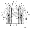
- FIG. 1 shows an inventive actuator module
- Figure 2 is a sectional view of the actuator module according to the invention along the line II-II in Figure 1
- Figure 3 is a sectional view of the actuator module according to the invention along the line II-II in Figure 1 a second embodiment.
- the actuator module according to the invention relates, for example, to a fuel injection valve which injects fuel from a fuel reservoir into a combustion chamber or a suction pipe of an internal combustion engine.
- a fuel injection valve has been proposed, for example, in the unpublished German patent application 103 10 790, the content of which is expressly intended to be part of the disclosure of this application.
- the actuator module has an actuator, for example a piezoelectric actuator 1, which is provided in an example cylindrical actuator sleeve 2.
- the actuator sleeve 2 in turn is arranged in an actuator housing 6, which is designed, for example, cylindrical.
- the actuator housing 6 is provided for example in a valve housing 14.
- the piezoactuator 1 is composed of a multiplicity of ceramic layers stacked on top of one another, which, stacked one above the other, form a so-called multilayer stack. Between the piezoelectric ceramic layers in each case an electrode layer is provided, which are printed, for example, on the ceramic layers by means of screen printing technology. The ceramic layers are electrically non-conductive and polarizable.
- the piezoelectric actuator 1 extends in the direction of an actuator axis 5 and is formed, for example, cuboid with a square or rectangular cross-section.
- the piezoelectric actuator 1 has two outer electrodes, a first outer electrode 3 and a second outer electrode 4, which are electrically connected to the electrode layers of the piezoelectric actuator 1, for example via so-called bonding wires.
- the outer electrodes 3,4, for example, have a diameter of 0.8 millimeters and are made of brass.
- an electrical voltage from a voltage source 27 abut, wherein the electrical voltage, for example by means of an electronic control unit 8, for example, clocked switched on or off.
- the actuator sleeve 2 is for example a cylindrical elastic tube spring, which protects the piezoelectric actuator 1 against external mechanical influences, for example bending stresses, tensile stresses and torsional stresses.
- a Bourdon tube is, for example, in the unpublished German patent application 103 10 787 the content of which is expressly intended to be part of the disclosure of this application.
- the piezoelectric actuator 1 has on the circumference, for example, a sheath 9, which surrounds the actuator 1 directly and the heat dissipation in the direction of the actuator sleeve 2 is used.
- the sheath 9 consists for example of an elastomer with a good thermal conductivity.
- a cylindrical centering cover 10 is provided with a centering opening 11, which projects through the piezoelectric actuator 1 in the direction of the actuator axis 5.
- the Zentrierdeckel 10 is placed for example on the piezoelectric actuator 1 and connected only by a transversely acting to Aktorachse 5 positive locking with this. In this way, the centering cover 10 is mechanically coupled to the piezoelectric actuator 1 only transversely to the actuator axis 5.
- the centering opening 11 is formed, for example, as the piezoelectric actuator 1 square.
- the centering cover 10 is made for example of a plastic.
- the outer electrodes 3,4 extend from the bonding wires connected to the electrode layers, starting from the jacket 9 of the piezoactuator 1 in the direction of the actuator axis 5 and penetrate the centering cover 10, the actuator sleeve 2 and the actuator housing 6, outside of the actuator housing 6 on a connection side 12 the actuator module to be contacted with an electrical connection line 28.
- the outer electrodes 3,4 are, for example, enclosed by the centering cover 10 in the direction of the voltage source 27 by an insulating layer 29.
- the valve housing 14, the actuator housing 6 and the actuator sleeve 2 are frontally, on the connection side 12 of the actuator module, closed by a housing cover 7, the For example, with a first shoulder 15 in the front of the actuator sleeve 2, with a second shoulder 16 projects into the front of the actuator housing 6 and with its outer periphery in the valve housing 14.
- the housing cover 7 centered in this way the actuator housing 6 and the actuator sleeve 2 in the valve housing 14. But it can also be provided separate cover, each of the valve housing 14, the actuator housing 6 and the actuator sleeve 2 close.
- the first paragraph 15 of the housing cover 7 is frictionally and / or materially connected to the actuator housing 2 and the second paragraph 16 to the actuator housing 6, for example, welded.
- the housing cover 7 has on the connection side 12 of the actuator module, for example, an input channel 17 which is connected for example to a fuel line 18 to fuel via the input channel 17 into a gap 32 between the valve housing 14 and the actuator housing 6 in the direction of a combustion chamber or a To guide the suction pipe facing outlet opening to a valve seat of the fuel injection valve.
- the first outer electrode 3 penetrates the centering cover 10 through a first passage opening 19 and the housing cover 7 through a first connection opening 21.
- the second outer electrode 4 projects through the centering cover 10 through a second passage opening 20 and the housing cover 7 through a second connection opening 22.
- a first centering sleeve 23 and a second centering sleeve 24 are provided on the centering cover 10, wherein the first centering sleeve 23, the first outer electrode 3 and the second centering sleeve 24, the second outer electrode 4 annular surrounds.
- the centering sleeves 23,24 are provided as a sleeve-shaped elevation on the centering cover 10, which are molded, for example, in one piece to the Zentrierdeckel 10 by injection molding and made of plastic.
- the centering sleeves 23,24 are, for example, conical, in order to facilitate in this way the threading into the connection openings 21,22.
- the centering sleeves 23,24 of the centering cover 10 center the piezoelectric actuator 1 in the actuator sleeve 2 by cooperation with the connection openings 21,22 in the housing cover 7 and acting transversely to the Aktorachse 5 positive connection between the centering cover 10 and the piezoelectric actuator 1. In this way an at least almost play-free connection between the centering cover 10 and the housing cover 7 is formed.
- the piezoelectric actuator 1 is also arranged centrally to the actuator housing 6 and the housing cover 7.
- the Zentrierdeckel 10 projects with the centering sleeves 23,24 into the connection openings 21,22 of the housing cover 7 and sets in this way the position of the piezoelectric actuator 1 in the actuator sleeve 2, since the piezoelectric actuator 1 positively connected to the centering cover 10 and the housing cover. 7 is firmly aligned to the actuator sleeve 2.
- the first centering sleeve 23 according to a first embodiment, a round cross section and the second centering sleeve 24 has an oval or elliptical cross-section, wherein the connection openings 21,22 each have a round cross-section.
- the connection between the piezoelectric actuator 1 and the housing cover 7 is not statically overdetermined, since the connection between the oval centering sleeve 24 and the circular connection opening 22 permits a translatory compensation movement, for example caused by thermal expansion.
- FIG. 2 shows in section a view of the actuator module according to the invention along the line II-II in Figure 1.
- connection openings 21,22 each have a round cross-section.
- the connection openings 21,22 each have a round cross-section.
- the connection openings 21,22 each have a crescent-shaped gap 26 in the radial direction to the actuator axis 5, so that the piezoelectric actuator 1 with the second outer electrode 4 in the direction of the first outer electrode 3 or in the first outer electrode 3 opposite direction, for example thermally contraction can contract or expand.
- the diameter of the connection openings 21,22, the diameter of the first centering sleeve 23 and the dimension of the largest diameter of the second centering sleeve 24 are almost equal.
- FIG. 3 shows in section a view of the actuator module according to the invention according to a second embodiment along the line III-III in Figure 1.
- the actuator module according to FIG. 3 differs from the actuator module according to FIG. 2 in that the first centering sleeve 23 and the second centering sleeve 24 have a round cross section, wherein the first connection opening 21 has a round cross section and the second connection opening 22 is formed as a slot 25 is.
- the slot 25 extends both in the direction of the first outer electrode 3 and in the first outer electrode 3 opposite direction.
- the diameter of the first connection opening 21 and the double measure of the radii of the elongated hole formed as the second connection opening 22 and the diameter of the centering sleeves 23,24 are almost equal.
- This variant is more complicated to manufacture, but offers for the piezoelectric actuator 1 a better possibility for compensating movement.
Landscapes
- Engineering & Computer Science (AREA)
- Chemical & Material Sciences (AREA)
- Combustion & Propulsion (AREA)
- Mechanical Engineering (AREA)
- General Engineering & Computer Science (AREA)
- Fuel-Injection Apparatus (AREA)
Claims (10)
- Module actionneur comprenant un actionneur dans une douille d'actionneur (2) contenue dans un boîtier d'actionneur (6) comprenant au moins un couvercle de centrage (10) disposé sur le côté frontal de l'actionneur (1), muni de deux ouvertures de passage, et un couvercle de boîtier muni de deux ouvertures de raccordement fermant le boîtier d'actionneur sur le côté frontal, deux électrodes extérieures (3, 4) de l'actionneur (1) s'étendant vers l'extérieur respectivement à travers l'une des ouvertures de passage du couvercle de centrage (10) et l'une des ouvertures de raccordement (21, 22) du couvercle de boîtier (7),
caractérisé en ce que
sur le couvercle de centrage (10) au moins deux douilles de centrage (23, 24) sont disposées, lesquelles entourent chacune les électrodes extérieures (3, 4) de façon annulaire et centrent l'actionneur (1) dans la douille d'actionneur (2) grâce à une coopération avec les ouvertures de raccordement (21, 22). - Module actionneur selon la revendication 1,
caractérisé en ce que
les douilles de centrage (23, 24) font saillie dans les ouvertures de raccordement (21, 22) du couvercle de boîtier (7) et forment au moins une liaison sensiblement sans jeu. - Module actionneur selon la revendication 1,
caractérisé en ce que
la première douille de centrage (23) présente une section transversale ronde et la deuxième douille de centrage (24) une section transversale ovale ou elliptique, les ouvertures de raccordement (21, 22) ayant chacune une section transversale ronde. - Module actionneur selon la revendication 1,
caractérisé en ce que
la première douille de centrage (23) et la deuxième douille de centrage (24) présentent une section transversale ronde et une première ouverture de raccordement (21) a une section transversale ronde et une deuxième ouverture de raccordement (22) présente la forme d'un trou oblong (25). - Module actionneur selon la revendication 3,
caractérisé en ce que
la deuxième douille de centrage (24) présente un diamètre maximum qui correspond approximativement au diamètre de la première douille de centrage (23). - Module actionneur selon la revendication 1,
caractérisé en ce que
la première douille de centrage (23) et la deuxième douille de centrage (24) sont en matière plastique. - Module actionneur selon la revendication 1,
caractérisé en ce que
l'actionneur (1) est un actionneur piézo-électrique. - Module actionneur selon la revendication 1,
caractérisé par
une enveloppe (9) en élastomère d'une bonne conductibilité thermique sur la périphérie l'actionneur (1). - Module actionneur selon la revendication 1,
caractérisé en ce que
le couvercle de centrage (10) présente une ouverture de centrage (11) traversée par l'actionneur (1). - Module actionneur selon la revendication 1,
caractérisé en ce que
le couvercle de boîtier (7) centre le boîtier d'actionneur (6) et la douille d'actionneur (2) dans un boîtier de soupape (14).
Applications Claiming Priority (2)
| Application Number | Priority Date | Filing Date | Title |
|---|---|---|---|
| DE102004012926A DE102004012926A1 (de) | 2004-03-17 | 2004-03-17 | Aktormodul |
| DE102004012926 | 2004-03-17 |
Publications (2)
| Publication Number | Publication Date |
|---|---|
| EP1577960A1 EP1577960A1 (fr) | 2005-09-21 |
| EP1577960B1 true EP1577960B1 (fr) | 2006-12-27 |
Family
ID=34833148
Family Applications (1)
| Application Number | Title | Priority Date | Filing Date |
|---|---|---|---|
| EP04106329A Expired - Lifetime EP1577960B1 (fr) | 2004-03-17 | 2004-12-06 | Module d'actionneur |
Country Status (2)
| Country | Link |
|---|---|
| EP (1) | EP1577960B1 (fr) |
| DE (2) | DE102004012926A1 (fr) |
Families Citing this family (5)
| Publication number | Priority date | Publication date | Assignee | Title |
|---|---|---|---|---|
| DE102005046122A1 (de) * | 2005-09-27 | 2007-03-29 | Robert Bosch Gmbh | Brennstoffeinspritzventil |
| DE102005050784A1 (de) * | 2005-10-24 | 2007-04-26 | Robert Bosch Gmbh | Kraftstoffeinspritzventile für Brennkraftmaschinen |
| DE102006006077B4 (de) | 2006-02-09 | 2009-04-09 | Continental Automotive Gmbh | Piezokeramischer Vielschicht-Aktor, Verfahren zum Herstellen eines piezokeramischen Vielschicht-Aktors und Einspritzsystem |
| DE202012007128U1 (de) * | 2012-07-23 | 2012-08-02 | Robert Bosch Gmbh | Ventil zum Zumessen von Fluid |
| DE102018212145A1 (de) | 2018-07-20 | 2020-01-23 | Brose Fahrzeugteile GmbH & Co. Kommanditgesellschaft, Würzburg | Elektromotor sowie Pumpe mit einem solchen Elektromotor |
Family Cites Families (5)
| Publication number | Priority date | Publication date | Assignee | Title |
|---|---|---|---|---|
| DE19715487C2 (de) * | 1997-04-14 | 2002-06-13 | Siemens Ag | Piezoelektrischer Aktor mit einem Hohlprofil |
| DE19940347B4 (de) * | 1999-08-25 | 2006-06-08 | Siemens Ag | Elektrische Verbindungsvorrichtung zum Aufsetzen auf Anschlußstifte eines elektrischen Bausteins |
| DE10251225B4 (de) * | 2002-11-04 | 2010-04-08 | Continental Automotive Gmbh | Piezoaktorkontaktierung für Einspritzventil |
| DE10253956A1 (de) * | 2002-11-19 | 2004-06-24 | Siemens Ag | Piezoaktorkontaktierung für Einspritzventil und Verfahren zu dessen Herstellung |
| DE10321694A1 (de) * | 2003-05-14 | 2004-12-02 | Robert Bosch Gmbh | Aktormodul |
-
2004
- 2004-03-17 DE DE102004012926A patent/DE102004012926A1/de not_active Withdrawn
- 2004-12-06 DE DE502004002441T patent/DE502004002441D1/de not_active Expired - Lifetime
- 2004-12-06 EP EP04106329A patent/EP1577960B1/fr not_active Expired - Lifetime
Also Published As
| Publication number | Publication date |
|---|---|
| EP1577960A1 (fr) | 2005-09-21 |
| DE102004012926A1 (de) | 2005-10-06 |
| DE502004002441D1 (de) | 2007-02-08 |
Similar Documents
| Publication | Publication Date | Title |
|---|---|---|
| EP1147306B1 (fr) | Soupape d'injection de carburant et procede pour la faire fonctionner | |
| EP1045973B1 (fr) | Soupape d'injection de carburant | |
| EP0976165A1 (fr) | Actionneur piezoelectrique a nouveau mode de contact et son procede de fabrication | |
| EP1906464A1 (fr) | Piézoacteur doté d'une gaine, destiné à la saisie dans un piézoinjecteur | |
| EP1829128B1 (fr) | Dispositif comprenant un element a memoire de forme | |
| DE10335019A1 (de) | Piezoaktor | |
| EP1577960B1 (fr) | Module d'actionneur | |
| EP1714024A1 (fr) | Passe-cable et partie de systeme de carburant pourvue d'un passe-cable | |
| WO2012130538A1 (fr) | Soupape pour le dosage d'un milieu | |
| DE102007000225B4 (de) | Piezostellglied | |
| EP2417346B1 (fr) | Actionneur piézoélectrique et soupape d'injection de combustible | |
| EP0469099A1 (fr) | Reglette pour le contact électrique simultane d'une pluralité d'injecteurs de carburant électromagnetiques. | |
| EP1587152B1 (fr) | Dispositif avec actionneur piézoélectrique | |
| EP1920473B1 (fr) | Piézoactionneur doté de contacts intérieurs | |
| DE102005042759A1 (de) | Piezoelektrischer Aktor | |
| EP1673534B1 (fr) | Douille de reception pour corps d'actionneur | |
| EP2396535B1 (fr) | Actionneur piezoelectrique, procede de production de l'actionneur et injecteur | |
| DE102006032743A1 (de) | Aktor zum Hubantrieb eines Stellglieds | |
| DE102014219147A1 (de) | Aktormodul mit einem Stapel von Piezokeramiken | |
| EP3036431B1 (fr) | Actionneur piézo-électrique pour injecteur de carburant et injecteur de carburant | |
| DE102009027101A1 (de) | Elastische Hülse für einen piezoelektrischen Aktor und Aktormodul | |
| DE10350061A1 (de) | Aktormodul | |
| EP1820960B1 (fr) | Soupape d'injection de carburant | |
| DE102004058643B4 (de) | Kraftstoffinjektor für eine Brennkraftmaschine | |
| DE112012005186B4 (de) | Einspritzventil |
Legal Events
| Date | Code | Title | Description |
|---|---|---|---|
| PUAI | Public reference made under article 153(3) epc to a published international application that has entered the european phase |
Free format text: ORIGINAL CODE: 0009012 |
|
| AK | Designated contracting states |
Kind code of ref document: A1 Designated state(s): AT BE BG CH CY CZ DE DK EE ES FI FR GB GR HU IE IS IT LI LT LU MC NL PL PT RO SE SI SK TR |
|
| AX | Request for extension of the european patent |
Extension state: AL BA HR LV MK YU |
|
| 17P | Request for examination filed |
Effective date: 20060321 |
|
| AKX | Designation fees paid |
Designated state(s): DE FR IT |
|
| GRAP | Despatch of communication of intention to grant a patent |
Free format text: ORIGINAL CODE: EPIDOSNIGR1 |
|
| GRAS | Grant fee paid |
Free format text: ORIGINAL CODE: EPIDOSNIGR3 |
|
| GRAA | (expected) grant |
Free format text: ORIGINAL CODE: 0009210 |
|
| AK | Designated contracting states |
Kind code of ref document: B1 Designated state(s): DE FR IT |
|
| REF | Corresponds to: |
Ref document number: 502004002441 Country of ref document: DE Date of ref document: 20070208 Kind code of ref document: P |
|
| ET | Fr: translation filed | ||
| PLBE | No opposition filed within time limit |
Free format text: ORIGINAL CODE: 0009261 |
|
| STAA | Information on the status of an ep patent application or granted ep patent |
Free format text: STATUS: NO OPPOSITION FILED WITHIN TIME LIMIT |
|
| 26N | No opposition filed |
Effective date: 20070928 |
|
| PGFP | Annual fee paid to national office [announced via postgrant information from national office to epo] |
Ref country code: IT Payment date: 20121222 Year of fee payment: 9 |
|
| PG25 | Lapsed in a contracting state [announced via postgrant information from national office to epo] |
Ref country code: IT Free format text: LAPSE BECAUSE OF NON-PAYMENT OF DUE FEES Effective date: 20131231 |
|
| REG | Reference to a national code |
Ref country code: FR Ref legal event code: PLFP Year of fee payment: 12 |
|
| PG25 | Lapsed in a contracting state [announced via postgrant information from national office to epo] |
Ref country code: IT Free format text: LAPSE BECAUSE OF NON-PAYMENT OF DUE FEES Effective date: 20131206 |
|
| REG | Reference to a national code |
Ref country code: FR Ref legal event code: PLFP Year of fee payment: 13 |
|
| PGFP | Annual fee paid to national office [announced via postgrant information from national office to epo] |
Ref country code: FR Payment date: 20161221 Year of fee payment: 13 |
|
| PGFP | Annual fee paid to national office [announced via postgrant information from national office to epo] |
Ref country code: DE Payment date: 20180223 Year of fee payment: 14 |
|
| REG | Reference to a national code |
Ref country code: FR Ref legal event code: ST Effective date: 20180831 |
|
| PG25 | Lapsed in a contracting state [announced via postgrant information from national office to epo] |
Ref country code: FR Free format text: LAPSE BECAUSE OF NON-PAYMENT OF DUE FEES Effective date: 20180102 |
|
| REG | Reference to a national code |
Ref country code: DE Ref legal event code: R119 Ref document number: 502004002441 Country of ref document: DE |
|
| PG25 | Lapsed in a contracting state [announced via postgrant information from national office to epo] |
Ref country code: DE Free format text: LAPSE BECAUSE OF NON-PAYMENT OF DUE FEES Effective date: 20190702 |