EP1577637A1 - Optischer Heterodyninterferometer für Formmessung - Google Patents
Optischer Heterodyninterferometer für Formmessung Download PDFInfo
- Publication number
- EP1577637A1 EP1577637A1 EP05005271A EP05005271A EP1577637A1 EP 1577637 A1 EP1577637 A1 EP 1577637A1 EP 05005271 A EP05005271 A EP 05005271A EP 05005271 A EP05005271 A EP 05005271A EP 1577637 A1 EP1577637 A1 EP 1577637A1
- Authority
- EP
- European Patent Office
- Prior art keywords
- light
- intensity
- interference light
- interference
- current component
- Prior art date
- Legal status (The legal status is an assumption and is not a legal conclusion. Google has not performed a legal analysis and makes no representation as to the accuracy of the status listed.)
- Granted
Links
- 230000003287 optical effect Effects 0.000 title claims abstract description 207
- 238000005259 measurement Methods 0.000 title description 48
- 230000001902 propagating effect Effects 0.000 claims abstract description 42
- 238000001514 detection method Methods 0.000 claims description 40
- 230000035559 beat frequency Effects 0.000 claims description 23
- 230000001360 synchronised effect Effects 0.000 claims description 5
- 238000005520 cutting process Methods 0.000 claims description 4
- 238000001444 catalytic combustion detection Methods 0.000 abstract description 105
- 238000012545 processing Methods 0.000 abstract description 28
- 238000005070 sampling Methods 0.000 description 142
- 238000000034 method Methods 0.000 description 33
- 230000000875 corresponding effect Effects 0.000 description 31
- 230000014509 gene expression Effects 0.000 description 25
- 238000004364 calculation method Methods 0.000 description 15
- 238000012935 Averaging Methods 0.000 description 12
- 230000001427 coherent effect Effects 0.000 description 9
- 238000009826 distribution Methods 0.000 description 8
- 238000006243 chemical reaction Methods 0.000 description 6
- 238000010586 diagram Methods 0.000 description 6
- 238000002834 transmittance Methods 0.000 description 6
- 238000003384 imaging method Methods 0.000 description 5
- 238000003860 storage Methods 0.000 description 5
- 0 C*(C)CCC(C)(*)C(CCC1)C1(CCCC1)C11CCCCCCC1 Chemical compound C*(C)CCC(C)(*)C(CCC1)C1(CCCC1)C11CCCCCCC1 0.000 description 4
- 238000003491 array Methods 0.000 description 4
- 230000001276 controlling effect Effects 0.000 description 4
- 230000008859 change Effects 0.000 description 3
- 230000004907 flux Effects 0.000 description 3
- 238000012634 optical imaging Methods 0.000 description 3
- 230000004044 response Effects 0.000 description 3
- 230000017531 blood circulation Effects 0.000 description 2
- 210000004087 cornea Anatomy 0.000 description 2
- 238000013461 design Methods 0.000 description 2
- 238000005516 engineering process Methods 0.000 description 2
- 238000000691 measurement method Methods 0.000 description 2
- 230000010363 phase shift Effects 0.000 description 2
- 238000004904 shortening Methods 0.000 description 2
- 238000004458 analytical method Methods 0.000 description 1
- 238000000149 argon plasma sintering Methods 0.000 description 1
- 230000002596 correlated effect Effects 0.000 description 1
- 230000003247 decreasing effect Effects 0.000 description 1
- 238000002059 diagnostic imaging Methods 0.000 description 1
- 230000000694 effects Effects 0.000 description 1
- 210000002889 endothelial cell Anatomy 0.000 description 1
- 231100001261 hazardous Toxicity 0.000 description 1
- 238000005286 illumination Methods 0.000 description 1
- 238000005304 joining Methods 0.000 description 1
- 239000007788 liquid Substances 0.000 description 1
- 239000004973 liquid crystal related substance Substances 0.000 description 1
- 239000013307 optical fiber Substances 0.000 description 1
- 230000005693 optoelectronics Effects 0.000 description 1
- 230000000737 periodic effect Effects 0.000 description 1
- 230000008569 process Effects 0.000 description 1
- 230000009467 reduction Effects 0.000 description 1
- 210000001525 retina Anatomy 0.000 description 1
- 230000035945 sensitivity Effects 0.000 description 1
- 230000003595 spectral effect Effects 0.000 description 1
- 238000003325 tomography Methods 0.000 description 1
Images


Classifications
-
- G—PHYSICS
- G01—MEASURING; TESTING
- G01B—MEASURING LENGTH, THICKNESS OR SIMILAR LINEAR DIMENSIONS; MEASURING ANGLES; MEASURING AREAS; MEASURING IRREGULARITIES OF SURFACES OR CONTOURS
- G01B9/00—Measuring instruments characterised by the use of optical techniques
- G01B9/02—Interferometers
- G01B9/02001—Interferometers characterised by controlling or generating intrinsic radiation properties
- G01B9/02007—Two or more frequencies or sources used for interferometric measurement
-
- G—PHYSICS
- G01—MEASURING; TESTING
- G01B—MEASURING LENGTH, THICKNESS OR SIMILAR LINEAR DIMENSIONS; MEASURING ANGLES; MEASURING AREAS; MEASURING IRREGULARITIES OF SURFACES OR CONTOURS
- G01B9/00—Measuring instruments characterised by the use of optical techniques
- G01B9/02—Interferometers
- G01B9/02001—Interferometers characterised by controlling or generating intrinsic radiation properties
- G01B9/02002—Interferometers characterised by controlling or generating intrinsic radiation properties using two or more frequencies
- G01B9/02003—Interferometers characterised by controlling or generating intrinsic radiation properties using two or more frequencies using beat frequencies
-
- G—PHYSICS
- G01—MEASURING; TESTING
- G01B—MEASURING LENGTH, THICKNESS OR SIMILAR LINEAR DIMENSIONS; MEASURING ANGLES; MEASURING AREAS; MEASURING IRREGULARITIES OF SURFACES OR CONTOURS
- G01B9/00—Measuring instruments characterised by the use of optical techniques
- G01B9/02—Interferometers
- G01B9/02041—Interferometers characterised by particular imaging or detection techniques
-
- G—PHYSICS
- G01—MEASURING; TESTING
- G01B—MEASURING LENGTH, THICKNESS OR SIMILAR LINEAR DIMENSIONS; MEASURING ANGLES; MEASURING AREAS; MEASURING IRREGULARITIES OF SURFACES OR CONTOURS
- G01B9/00—Measuring instruments characterised by the use of optical techniques
- G01B9/02—Interferometers
- G01B9/02055—Reduction or prevention of errors; Testing; Calibration
- G01B9/02062—Active error reduction, i.e. varying with time
- G01B9/02067—Active error reduction, i.e. varying with time by electronic control systems, i.e. using feedback acting on optics or light
- G01B9/02069—Synchronization of light source or manipulator and detector
-
- G—PHYSICS
- G01—MEASURING; TESTING
- G01B—MEASURING LENGTH, THICKNESS OR SIMILAR LINEAR DIMENSIONS; MEASURING ANGLES; MEASURING AREAS; MEASURING IRREGULARITIES OF SURFACES OR CONTOURS
- G01B2290/00—Aspects of interferometers not specifically covered by any group under G01B9/02
- G01B2290/45—Multiple detectors for detecting interferometer signals
-
- G—PHYSICS
- G01—MEASURING; TESTING
- G01J—MEASUREMENT OF INTENSITY, VELOCITY, SPECTRAL CONTENT, POLARISATION, PHASE OR PULSE CHARACTERISTICS OF INFRARED, VISIBLE OR ULTRAVIOLET LIGHT; COLORIMETRY; RADIATION PYROMETRY
- G01J9/00—Measuring optical phase difference; Determining degree of coherence; Measuring optical wavelength
- G01J9/02—Measuring optical phase difference; Determining degree of coherence; Measuring optical wavelength by interferometric methods
- G01J2009/0234—Measurement of the fringe pattern
Definitions
- the present invention relates to an optical image measuring apparatus employing a structure in which an object to be measured which is particularly a light scattering medium is irradiated with a light beam and a surface form or inner form of the obj ect to be measured is measured based on a reflected light beam or a transmitted light beam to produce an image of a measured form. More particularly, the present invention relates to an optical image measuring apparatus for measuring the surface form or inner form of the object to be measured by using an optical heterodyne detection method to produce the image of the measured form.
- optical imaging techniques for producing an image of a surface or inner portion of an object to be measured using a laser light source or the like.
- optical imaging technique is not hazardous to human bodies. Therefore, its application to the field of medical imaging is highly desired.
- An example of a typical method of the optical imaging technique is a low coherent interference method (also called “optical coherent tomography” or the like).
- This method uses the low coherence of a broad band light source having a wide spectral width, such as a super luminescent diode (SLD).
- SLD super luminescent diode
- reflection light from an object to be measured or light transmitting therethrough can be detected with a superior distance resolution of ⁇ m order (for example, see Naohiro Tanno, Kogaku (Japanese Journal of Optics), Volume 28, No. 3, 116 (1999)).
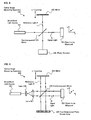
- FIG. 8 shows a fundamental structure of a conventional optical image measuring apparatus based on a Michelson interferometer, serving as an example of an apparatus using the low coherent interference method.
- An optical image measuring apparatus 100 includes a wide band light source 101, a mirror 102, a beam splitter (half mirror) 103, and a photo detector 104.
- An obj ect to be measured 105 is made of a scattering medium.
- a light beam from the broad band light source 101 is divided by the beam splitter 103 into two parts, that is, a reference light R propagating to the mirror 102 and a signal light S propagating to the object to be measured 105.
- the reference light R is a light beam reflected by the beam splitter 103.
- the signal light S is a light beam transmitting through the beam splitter 103.
- the propagating directionof the signal light S is set as a z-axis and a plane orthogonal to the propagating direction of the signal light S is defined as an x-y plane.
- the mirror 102 is shiftable ineitherthe forward and backward directions, as indicated by a double-headed arrow in Fig. 8 (z-scanning direction).
- the reference light R is subj ected to a Doppler frequency shift by z-scanning when is reflected by the z-scanning mirror 102.
- the signal light S is reflected from the surface of the object to be measured 105 and from the inner layers thereof when the object to be measured 105 is irradiated with the light. Because the object to be measured 105 is a scattering medium, the signal light S reflected from the object may include the multiply scattered light wave having random phases.
- the signal light reflected from the object to be measured 105 and the reference light reflected from the.mirror 102 to be subjected to the frequency shift are superimposed on each other by the beam splitter 103 to produce an interference light.
- interference occurs only when a difference in optical path length between the signal light S and the reference light R is within the coherent length, of the broad band light source 101, which is of the order of several ⁇ m to tens of ⁇ m.
- the component of the signal light S whose phase is correlated to that of the reference light R interferes with the reference light R. That is, only the coherent signal light component of the signal light S selectively interferes with the reference light R.
- the position of the mirror 102 is shifted by the z-scanning operation to vary the optical path length of the reference light R, so a reflectance profile of the inner layers of the object to be measured 105 is measured.
- the interference light is detected by the photo detector 104 during each z-scan.
- An electrical signal (heterodyne signal) output from the photo detector 104 provides a backscatter profile of the inner layers of object to be measured 105, and a two-dimensional cross-sectional image of the object to be measured 105 is produced by scanning the signal light S across the object to be measured 105 while recording the reflectance profile at each transverse position (see Naohiro Tanno, Kogaku (Japanese Journal of Optics), Volume 28, No. 3, 116 (1999)).
- a heterodyne signal as expressed by the following expression is outputted from the photo detector (for example, Yoshizawa and Seta "Optical Heterodyne Technology (revised edition)", New Technology Communications (2003), p.2).
- the third term of the right side of the expression (1) indicates an alternating current electrical signal and the frequency f if thereof is equal to the frequency difference between the reference light R and the signal light S.
- the frequency f if of an alternating current component of the heterodyne signal is called a beat frequency or the like.
- the first and second terms of the right side of the expression (1) indicate the direct current components of the heterodyne signal and correspond to the background light intensity.
- the two-dimensional cross-sectional image is intended to be obtained by means of the conventional low coherent interference method, it is necessary to scan the signal light beam S across the reflectance profile at the object to be measured 105 and to successively detect reflection light waves from each transverse position. Therefore, the measurement of the object to be measured 105 can be time consuming. In addition, it is hard to shorten a measurement time in view of measurement fundamentals.
- an optical image measuring apparatus 200 for shortening a measurement time has been proposed.
- Fig. 9 shows a fundamental structure of an example of such an apparatus.
- an optical image measuring apparatus 200 includes a broad band light source 201, a mirror 202, a beam splitter (half mirror) 203, a two-dimensional photo sensor array 204 serving for light detection, and lenses 206 and 207.
- a light beam from the light source 201 is converted into a parallel light flux by the lenses 206 and 207 and a beam diameter thereof is increased thereby.
- the parallel light flux is divided by the beam splitter 203 into two, that is, the reference light R and the signal light S.
- the reference light R is subjected to a Doppler frequency shift by z-scanning of the mirror 202.
- the signal light S is incident on the object to be measured 205 over a wide area of the x-y plane, as a consequence of a widened beam diameter. Therefore, the signal light S reflected from the object to be measured 205 contains information related to the surface and inner portion of the object to be measured 205 over a wide area.
- the reference light R and the signal light S are superimposed on each other by the beam splitter 103 and detected by the elements (photo sensors) arranged in parallel on the surface of the two-dimensiorial photo sensor array 204. Thus, it is possible to obtain a two-dimensional cross-sectional image of the object to be measured 205 in real time without scanning the signal light S.
- the optical image measuring apparatus includes a light source for emitting a light beam, an interference optical system, and a signal processing portion.
- the interference optical system the light beam emitted from the light source is divided into two, that is, a signal light propagating through an examined object locating position in which an obj ect to be examined is located, and a reference light propagating along an optical path different from an optical path passing through the examined object locating position.
- the optical interference system includes a frequency shifter, light cutoff devices, and photo sensors.
- the frequency shifter shifts a frequency of the signal light and a frequency of the reference light relative to each other.
- the interference light is divided into two parts.
- the light cutoff devices periodically cut off the two divided parts of the interference light to generate two interference light pulse trains with a phase difference of 90 degrees therebetween.
- the photo sensors respectively receive the two interference light pulse trains.
- the photo sensors each have a plurality of light receiving elements which are spatially arranged and each of which separately obtains a light receiving signal.
- the signal processing portion combines a plurality of light receiving signals obtained by each of the photo sensors to generate signals of the signal light which correspond to respective points of interest of a surface or inner layers of the object to be examined which is located in the examined obj ect locating position on a propagation path of the signal light.
- the interference light in which the reference light and the signal light interfere with each other is divided into two parts and the two parts of the interference light are received by the two photo sensors (two-dimensional photo sensor arrays) and respectively sampled by the light cutoff devices disposed in fronts of both sensor arrays.
- a phase difference of ⁇ /2 is provided between sampling periods of the two divided parts of the interference light. Therefore, an intensity of the signal light and an intensity of reference light which compose background light of the interference light and phase quadrature components (sine component and cosine component) of the interference light are detected.
- an intensity of the background light included in the outputs from both the sensor arrays is subtracted from the outputs of both the sensor arrays to calculate two phase quadrature components of the interference light.
- An amplitude of the interference light is obtained based on a result obtained by calculation.
- the interference light is continuously received with the shutter opened and time averaging of a result obtained by receiving the light is performed to obtain the direct current component.
- other obtaining methods are not specifically disclosed, so the degree of freedom of a measurement mode is small. Therefore, in order to improve the operability and the degree of freedom of an apparatus structure, it may be necessary to devise other measurement modes.
- the optical image measuring apparatus includes a light source for emitting a light beam and an interference optical system.
- the interference optical system the light beam emitted from the light source is divided into two, that is, signal light propagating through an examined object locating position in which an object to be examined is located and reference light propagating on an optical path different from an optical path passing through the examined object locating position.
- the signal light propagating through the examined object locating position and the reference light propagating on the different optical path are superimposed on each other to produce interference light in which the signal light and the reference light interfere with each other.
- the interference optical system includes a frequency shifter and an optical device.
- the frequency shifter shifts a frequency of the signal light and a frequency of the reference light relative to each other.
- the optical device is disposed on an optical path of at least one of the signal light and the reference light and periodically cuts off light.
- the cutoff frequency of the optical device is set to be equal to a frequency difference between the signal light and the reference light. According to the optical image measuring apparatus, the interference light can be sampled at the cutoff frequency equal to a beat frequency, so suitable optical heterodyne measurement is realized.
- the direct current component composed of the background light can be obtained by one-time measurement without separate measurement in the optical image measuring apparatus described in JP 2001-330558 A and JP 3245135 B, simple measurement is realized to shorten a measurement time. However, it is hard to realize this by the optical image measuring apparatus described in those patent documents.
- An object of the present invention is to provide an optical image measuring apparatus capable of effectively obtaining a direct current component of a heterodyne signal composed of background light of interference light.
- Another obj ect of the present invention is to provide an optical image measuring apparatus in which usefulness is improved by an increase in degree of freedom of a sampling mode for interference light.
- an optical image measuring apparatus for forming an image of an object to be measured based on interference light, including: a light source for emitting a light beam; an interference optical system that divides the light beam emitted from the light source into signal light propagating through the object to be measured and reference light propagating through a predetermined reference object, shifts a frequency of the signal light and a frequency of the reference light relative to each other, and then superimposes the signal light propagating through the object to be measured and the reference light propagating through the predetermined reference object on each other to produce the interference light; intensity modulating means for modulating an intensity of the interference light at a predetermined frequency; a photo detector for receiving the interference light whose intensity is modulated and converting the received interference light into an electrical signal to be outputted; and calculating means for calculating an intensity of a direct current component composed of background light of the interference light based on the electrical signal outputted from the photo detector.
- an optical image measuring apparatus including: a light source for emitting a light beam; an interference optical system that divides the light beam emitted from the light source into signal light propagating through the object to be measured and reference light propagating through a predetermined reference object, shifts a frequency of the signal light and a frequency of the reference light relative to each other, and then superimposes the signal light propagating through the object to be measured and the reference light propagating through the predetermined reference object on each other to produce the interference light; optical path dividing means for driving an optical path of the interference light produced by the optical interference system into a plurality of optical paths to produce a plurality of interference light beams; at least one intensity modulating means for modulating an intensity of at least one of the interference light beams at a predetermined frequency, which is provided on at least one first optical path of the plurality of optical paths; a plurality of photo detectors each provided on each of the plurality of optical paths, where at least one first photo detector of the plurality of
- the term "at least one first (second) optical path” means an arbitrary number of optical paths out of the plural (N) optical paths, that is, 1 to N optical paths.
- the predetermined optical path includes at least two optical paths, on each of which the intensity modulating means is provided, each of the at least two intensity modulating means provided on the optical paths modulates the intensity of the interference light beam such that a part of the interference light beam in which a phase difference is ⁇ (180 degrees) is received by the photo detector provided on a corresponding optical path, and the calculating means time-averages the electrical signals outputted from the photo detectors to calculate the intensity of the direct current component.
- the optical image measuring apparatus in the optical image measuring apparatus according to the second aspect of the present invention, the optical image measuring apparatus according to the second aspect, wherein the predetermined optical path includes an optical path in which the intensity modulating means is not provided, and the calculating means time-averages the electrical signal outputted from the photo detector located on the optical path in which the intensitymodulating means is not provided to calculate the intensity of the direct current component.
- the intensity modulating means modulates the intensity of the interference light beam plural times such that a part of the interference light beam in which a phase difference is ⁇ is received by the photo detector, the photo detector receives the interference light beam corresponding to each intensity modulation and outputs the received interference light beam as an electrical signal, and the calculating means time-averages the electrical signal corresponding to each intensity modulation which is outputted from the photo detector to calculate the intensity of the direct current component.
- the intensity modulating means modulates the intensity of the interference light beam at a frequency which is not synchronized with a beat frequency of the interference light beam
- the calculating means time-averages the electrical signal outputted from the photo detector based on the interference light beam whose intensity is modulated at the frequency to calculate the intensity of the direct current component.
- an optical image measuring apparatus for forming an image of an object to be measured based on interference light, including: a light source for emitting a light beam; an optical interference system that divides the light beam emitted from the light source into signal light propagating through the object to be measured and reference light propagating through a predetermined reference object, shifts a frequency of the signal light and a frequency of the reference light relative to each other, and then superimposes the signal light propagating through the object to be measured and the reference light propagating through the predetermined reference object on each other to produce the interference light; intensity modulating means for modulating an intensity of the interference light at a predetermined frequency; photo detection means for receiving the interference light whose intensity is modulated and converting the received interference light into an electrical signal to be outputted; and calculating means for calculating an intensity of a direct current component composed of background light of the interference light and at least one of an intensity and phase of an alternating current component of the interference light based on the electrical signal outputted from photo detection
- the optical image measuring apparatus further includes light receiving time changing means for changing a light receiving time of the interference light beam received by the photo detection means between a first light receiving time equal to or longer than a beat period of the interference light beam and a second light receiving time shorter than the beat period in accordance with the beat period, wherein the calculating means time-averages an electrical signal outputted from the photo detection means to calculate the intensity of the direct current component when the light receiving time is changed to the first light receiving time by the light receiving time changing means, and calculates at least one of the intensity and phase of the alternating current component based on an electrical signal outputted from the photo detection means when the light receiving time is changed to the second light receiving time and the direct current component whose intensity is calculated corresponding to the first light receiving time.
- the light receiving time changing means changes the light receiving time every beat period of the interference light, and the first light receiving time is the beat period.
- the light receiving time changing means changes the light receiving time everybeat period of the interference light, and the second light receiving time is half of the beat period.
- the predetermined frequency at which the intensity of the interference light is modulated by the intensity modulating means is an integral multiple of a beat frequency of the interference light.
- the intensity modulating means includes shutter means for cutting off the interference light at the predetermined frequency.
- the optical image measuring apparatus includes: the intensity modulating means for modulating the intensity of the interference light at the predetermined frequency; the photo detection means for receiving the interference light whose intensity is modulated and converting the received interference light into the electrical signal to be outputted; and the calculating means for calculating the intensity of the direct current component composed of the background light of the interference light based on the outputted electrical signal. Consequently, it is possible to effectively obtain the direct current component composed of the background light of the interference light.
- the direct current component can be obtained based on the electrical signal outputted from one or two photo detectionmeans . Consequently, it is possible to effectively obtain the direct current component according to the number of photo detection means provided in the optical image measuring apparatus.
- the direct current component can be obtained based on the electrical signal outputted from the photo detection means on the optical path in which the intensity modulating means is not provided. Consequently, an apparatus structure can be simplified.
- the direct current component is effectively calculated corresponding to the change of the light receiving time of the interference light received by the photo detection means, to the first light receiving time.
- the alternating current component is calculated based on a result obtained by calculation of the direct current component, corresponding to the change of the light receiving time to the second light receiving time. Consequently, when the optical image measuring apparatus is applied to measurement performed during, for example, scanning in a depth direction of the obj ect to be measured (z-scanning), the alternating current component can be successively obtained based on a value of the direct current component calculated just before. Thus, the measurement precision can be improved.
- the interference light can be sampled at various frequencies. Consequently, it is possible to increase the degree of freedom of the structure.
- an intensity of the interference light is periodically modulated.
- the periodically modulated interference light is received and outputted as an electrical signal (heterodyne signal).
- the intensity of the direct current component is calculated based on the outputted heterodyne signal.
- various sampling modes effective in obtaining characteristics of the interference light are provided. Examples of the characteristics of the interference light include the direct current component indicated in the above-mentioned expression (1), a signal intensity of the interference light, and a spatial phase distribution thereof.
- an optical image measuring apparatus having a structure capable of obtaining the intensity of the direct current component composed of the background light, the signal intensity of the interference light, and the spatial phase distribution thereof based on the heterodyne signals obtained from three interference light beams into which the interference light is divided will be described as an embodiment of the present invention.
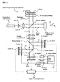
- Fig. 1 shows an example of a schematic structure showing an optical image measuring apparatus 1 according to the present invention, which is constructed to divide the interference light into three to perform measurement.
- the optical image measuring apparatus 1 is an apparatus available for, for example, medical care and industry and has a structure for obtaining two-dimensional sectional images of an object to be measured O which is made of a scattering medium at respective depths (in z-direction) to form a three-dimensional image.
- the optical image measuring apparatus 1 includes a wide band light source 2, lenses 3 and 4, a beam splitter 5, and a mirror 7.
- the light source 2 is composed of a SLD, a light emitting diode (LED), or the like and outputs a low-coherent light beam.
- the lenses 3 and 4 convert the light beams from the light source 2 into a parallel light flux and increase a beam diameter thereof.
- the beam splitter 5 divides the light beam into signal light S and reference light R and superimposes the signal light S and the reference light R on each other to produce interference light L.
- the mirror 7 is a total reflection mirror.
- the light source 2 suitably outputs the light beam such as continuous light or pulse light.
- a coherent length of an available near-infrared region SLD is about 30 ⁇ m and a coherent length of an LED is about 10 ⁇ m.
- a drive device for moving the mirror 7 in a propagating direction of the reference light (z-scanning) is provided.
- a frequency shifter 6 composed of an optoelectronic modulator, an acoustooptic modulator, or the like is disposed immediately in front of the mirror 7 and shifts a frequency of the reference light R passing therethrough.
- the frequency shifter 6 is unnecessary.
- the apparatus may be constructed such that both the frequency shifter 6 and the z-scanning can be used.
- the lenses 3 and 4, the beam splitter 5, the frequency shifter 6, and the mirror 7 compose an "interference optical system” in the present invention.
- the mirror 7 composes a "reference object” in the present invention.
- the optical image measuring apparatus 1 further includes an imaging lens group 8, beam splitters 11 and 12, CCDs (cameras) 21, 22, and 23, and shutters 31, 32, and 33.
- the imaging lens group 8 images the interference light L produced by the beam splitter 5.
- the beam splitters 11 and 12 divide the interference light L into three interference light beams L1, L2, and L3.
- Each of the CCDs 21, 22, and 23 is a storage type two-dimensional photo sensor array for interference light beam detection.
- the shutters 31, 32, and 33 are disposed immediately in front of the CCDs 21, 22, and 23, respectively and periodically cut off the interference light beams L1, L2, and L3, respectively.
- Each of the shutters 31, 32, and 33 is, for example, a high-speed shutter such as a liquid crystal shutter.
- the shutters 31, 32, and 33 are not necessarily disposed immediately in front of the CCDs 21, 22, and 23, respectively.
- the shutters 31, 32, and 33 can be respectively disposed at arbitrary positions on respective optical paths joining branch points of the interference light beams L1, L2, and L3 separated by the beam splitters 11 and 12 with the CCDs 21, 22, and 23. That is, the shutters 31, 32, and 33 may be disposed at positions in which the respective interference light beams L1, L2, and L3 can be cut off to change the quantities of light beams received by the CCDs 21, 22, and 23 to 0.
- the beam splitters 11 and 12 compose an "optical path dividing means" in the present invention.
- the CCDs 21, 22, and 23 composes a "photo detection means” in the present invention.
- the shutters 31, 32, and 33 compose an "intensity modulating means” and a “shutter means” in the present invention.
- the optical image measuring apparatus 1 further includes a pulse signal generator 50 and phase shifters 41, 42, and 43.
- the pulse signal generator 50 generates a pulse signal.
- the phase shifters 41, 42, and 43 each shift a phase of the pulse signal generated by the pulse signal generator 50 to produce timing signals for separately controlling open-and-close timings of the respective shutters 31, 32, and 33.
- the respective shutters 31, 32, and 33 periodically cut off the interference light beams L1, L2, and L3 , respectively, in response to the timing signals from the phase shifters 41, 42, and 43 at predetermined frequencies in order to sample the respective interference light beams. Therefore, the respective CCDs 21, 22, and 23 periodically receive the corresponding interference light beams L1, L2, and L3. As shown in Fig. 2C later, each of the interference light beams is received as a periodic pulse train. At this time, the respective shutters 31, 32, and 33 are separately opened and closed, so the pulses of the interference light beams L1, L2, and L3 detected by the CCDs 21, 22, and 23 have predetermined phase differences.
- the CCDs 21, 22, and 23 perform photoelectric conversion on the interference light beams L1, L2, and L3 which are detected at each pixel and output heterodyne signals which are results obtained by the conversion to a signal processing portion 60.
- Each of the heterodyne signals is an electrical signal reflecting the intensity and phase of the detected interference light beam.
- the signal processing portion 60 is a "calculating means" in the present invention, which executes calculation processing described later based on the heterodyne signals outputted from the CCDs 21, 22, and 23.
- the signal processing portion 60 also analyzes a result obtained by the calculation processing, forms various images including a two-dimensional sectional image of the object to be measured O based on the analyzed result, and causes a display device such as a monitor device which is not shown to display the images.
- the signal processing portion 60 is composed of, for example, a computer which includes a storage device storing a predetermined calculationprogram, such as a ROM, and a CPU executing the calculation program.
- a beam diameter of a light beam emitted from the light source 2 is increased by the lenses 3 and 4.
- the light beam is divided into the signal light S and the reference light R by the beam splitter 5.
- the signal light S is incident on the object to be measured O and then incident on the beam splitter 5 again as a reflection light wave including information related to a surface form and inner form of the object to be measured O.
- the reference light R passes through the frequency shifter 6 to be subjected to frequency shift, and then propagates to the mirror 7 and is reflected thereon.
- the reflected reference light R passes through the frequency shifter 6 again to be subjected to additional frequency shift and is incident on the beam splitter 5 again.
- the frequency of the reference light R may be shifted by z-scanning of the mirror 7.
- a part of the signal light S from the object to be measured O is reflected on the beam splitter 5. Simultaneously, a part of the reference light R subjected to the frequency shift transmits through the beam splitter 5. Therefore, the signal light S and the reference light R are superimposed on each other by the beam splitter 5 to produce the interference light L.
- the interference light L passes through the imaging lens group 8 and propagates to the beam splitter 11.
- An optical path of the interference light L is divided into two by the beam splitter 11.
- the interference light beam L1 reflected on the beam splitter 11 is detected by the CCD 21 through the shutter 31.
- An optical path of interference light transmitting through the beam splitter 11 is further divided into two by the beam splitter 12.
- the interference light beam L2 reflected on the beam splitter 12 is detected by the CCD 22 through the shutter 32.
- the interference light beam L3 transmitting through the beam splitter 12 is detected by the CCD 23 through the shutter 33.
- an interference light dividing ratio of the beam splitter 11 that is, an intensity ratio of the transmitted interference light to the reflected interference light beam L1 be 2:1. In other words, it is desirable that the beam splitter 11 transmit 2/3 of the incident light and reflect 1/3 thereof. In addition, it is desirable that an intensity ratio of the interference light beam L3 transmitting through the beam splitter 12 to the interference light beam L2 reflected thereon be 1:1. In other words, it is desirable that the beam splitter 12 transmit 1/2 of the incident light and reflect 1/2 thereof. Therefore, intensity levels of the interference light beams L1, L2, and L3 detected by the CCDs 21, 22, and 23 are made equal to one another, so this is suitable for performing calculation processing described later. An intensity ratio between the divided interference light beams is not limited to those and thus can be set as appropriate.
- the optical image measuring apparatus 1 the interference light beams -L1, L2, and L3 for which predetermined phase differences are provided according to the open-and-close timings of the shutters 31, 32, and 33 are sampled for detection. Therefore, the intensity of the direct current component composed of the background light, the signal intensity of the interference light L, and the spatial phase distribution thereof are obtained by one-time measurement without a time difference.
- sampling functions for controlling the open-and-close timings of the shutters 31, 32, and 33 are set in advance.
- the phases of the pulses periodically generated by the pulse signal generator 50 are shifted by the phase shifters 41, 42, and 43 and the phase-shifted pulses are respectively outputted to the shutters 31, 32, and 33 to produce the sampling functions.
- Figs. 2A to 2C are explanatory diagrams showing sampling operation of the interference light beam L1 which is performed by the shutter 31.
- Fig. 2A shows a time waveform of the interference light beam L1 received by the CCD 21.
- a heterodyne signal related to the interference light beam L1 can be expected to be a signal in which a direct current component composed of the background light proportional to the intensity of the reference light R and the intensity of the signal light S is superimposed on an alternating current component having a beat frequency of the interference light beam L1 (which is called a beat signal or the like).
- the interference light beam L1 is sampled by periodically opening and closing (switching on and off) the shutter 31 based on a sampling function m 1 (t) shown in Fig. 2B.
- Fig. 2C schematically shows a time waveform of the interference light beam L1 which is allowed to enter the CCD 21 when the interference light beam L1 is sampled using the sampling function m 1 (t).
- a difference between the frequency f sm of the sampling function m 1 (t) and the beat frequency f if of the heterodyne signal which is indicated in the expression (1) ( ⁇ f
- ) is set to a value sufficiently smaller than a response frequency of the CCD 21 serving as the storage type photo sensor. Therefore, a part of the interference light beam L1 having substantially the same phase is sampled during each period thereof.
- an output i 1 (t) from the CCD 21 that receives the interference light beam L1 is proportional to the amount of photocharge stored in the CCD 21 during a measurement period. More specifically, the output i 1 (t) is expressed by the following expression (for example, see M. Akiba, K. P. Chan, and N. Tanno, Optics Letters, Vol. 28, 816 (2003)).
- ⁇ -> indicates a time average produced by a storage effect of the CCD 21.
- ⁇ indicates an initial phase value for measurement and K 1 indicates photo detection efficiency including reflectance of the beam splitter 11 and a photoelectric conversion rate of the CCD 21.
- the interference light beam L2 is sampled by the shutter 32 whose open-and-close timings are controlled based on a predetermined sampling function m 2 (t), and is then detected by the CCD 22.
- the sampling function m 2 (t) has a waveform of a rectangular train with a duty of 50% and a frequency f sm thereof is equal to that of the sampling function m 1 (t) for sampling the interference light beam L1.
- the sampling function m 2 (t) has a phase difference ⁇ 1,2 with the sampling function m 1 (t).
- the phase difference ⁇ 1,2 is provided by setting phase shift amounts produced by the phase shifters 41 and 42 in advance. Under the above-mentioned condition, the following output i 2 (t) is obtained from the CCD 22 based on the same fundamentals as the expression (2).
- K 2 indicates photo detection efficiency including transmittance of the beam splitter 11, reflectance of the beam splitter 12, and a photoelectric conversion rate of the CCD 22.
- each of the outputs from the CCDs 21 and 22 includes the term of an intensity Is of the signal light S and the term of an intensity I r of the reference light R.
- the output from the CCD 21 includes the term related to an amplitude ⁇ (I s I r ) of the interference light beam L1 and a phase (2 ⁇ ft + ⁇ ) thereof.
- the output from the CCD 22 includes the term related to an amplitude ⁇ (I s I r ) of the interference light beam L2 and a phase (2 ⁇ ft + ⁇ 1,2 ) thereof.
- the interference light beam L3 is sampled by the shutter 33 whose open-and-close timings are controlled based on a sampling function m 3 (t), and is then detected by the CCD 23.
- the sampling function m 3 (t) has a waveform of a rectangular train with a duty of 50% and a frequency f sm thereof is equal to that of the sampling function m 1 (t) for sampling the interference light beam L1.
- the sampling function m 3 (t) has a phase difference ⁇ 1,3 with the sampling function m 1 (t).
- the phase difference ⁇ 1,3 is provided by setting phase shift amounts produced by the phase shifters 41 and 43 in advance. In this time, the following output i 3 (t) is obtained from the CCD 23 based on the same fundamentals as the expression (2).
- K 3 indicates photo detection efficiency including respective transmittances of the beam splitter 11 and 12 and a photoelectric conversion rate of the CCD 23.
- phase difference ⁇ 1,2 between the sampling function m 1 (t) and the sampling function m 2 (t) is set to - ⁇ /2.
- the phase difference ⁇ 1,3 between the sampling function m 1 (t) and the sampling function m 3 (t) is set to ⁇ /2.
- an intensity S 1 of the direction current component of the heterodyne signal which is composed of the background light of the interference light L and phase quadrature components (sine component and cosine component) S 2 and S 3 thereof are expressed by the following respective expressions.
- the intensity of the direct current component corresponding to the background light of the interference light L can be calculated based on the electrical signals from the two CCDs 22 and 23 of the three CCDs 21, 22 and 23.
- the amplitude of the heterodyne signal expressed by the expression (1) is expressed by the following expression. I s I r ⁇ S 2 2 + S 3 2
- a proportionality factor related to the right side is ⁇ /4.
- the amplitude of the heterodyne signal can be calculated using the direct current component obtained by the expression (5). Therefore, when the direct current component is added to the amplitude of the heterodyne signal, the intensity of the heterodyne signal, that is, the intensity of the interference light L can be obtained.
- the optical image measuring apparatus 1 is effective for image measurement in which the intensity of the background light is hard to measure in advance, such as optical sectional image measurement for a moving object. It is unnecessary to separately measure the intensity of the direct current component composed of the background light, so a measurement process can be simplified. Thus, measurement trouble is reduced to shorten a measurement time.
- the spatial phase distributionof the interference light L canbe obtained for imaging by the following measurement method.
- a signal S 4 does not depend on the amplitude of the interference light L and includes only phase information thereof. Therefore, a phase ⁇ (x, y, t 1 ) of the heterodyne signal which is outputted from each of pixels of the CCDs 21, 22, and 23, each of which is the two-dimensional photo sensor array, is expressed by the following expression.
- (x, y) indicate positional coordinates of each of the pixels which are set on the CCDs.
- the second term 2 ⁇ ft 1 of the expression (10) is an instantaneous phase value of an alternating current signal having a frequency ⁇ f of zero or substantially zero at the measurement time t 1 and kept constant regardless of a position (that is, variables x, y) of a pixel of each of the CCDs 21, 22, and 23.
- a spatial phase distribution of the heterodyne signals that is, a spatial phase distribution of the interference light L can be imaged. It is expected that such measurement of the spatial phase distribution of the interference light is effective for image measurement using phase difference values as references, such as high precision measurement on a mirror surface, which is performed by a heterodyne interference method.
- ⁇ f 1 2 ⁇ ⁇ ( x , y , t 1 ) - ⁇ ( x , y , t 2 ) t 1 - t 2
- the frequency f if of the heterodyne signal that is, the frequency of the interference light L can be calculated based on a result calculated from the expression (11). It is expected that the heterodyne frequency measuring method is effectively usable for Doppler velocity measurement using a heterodyne interference method, such as blood flow measurement on a fundus of an eye to be examined.
- each of the shutters 31, 32, and 33 such as the high-speed shutters is used as the intensity modulating means in the present invention.
- the intensity modulating means is not limited to this.
- a spatial light modulator (SLM) whose transmittance for transmitting the interference light can be periodically changed is provided instead of such a shutter means that completely cuts off the interference light. Therefore, the intensity of the interference light received by a photo detection means such as the CCD can be modulated to sample the interference light. That is, the shutter means changes the intensity of the interference light received by the photo detection means between 0 and 100 (maximal intensity).
- a structure for periodically changing the intensity of the interference light between, for example, 10 and 80 can be applied as the intensity modulating means in the present invention.
- the modulated intensity of the interference between the two values it is possible to employ a method of periodically switching among at least three values or a method of periodically and successively switching between two values based on a sampling mode or the like.
- An interval for intensity modulation may be determined in view of the sensitivity of the CCD, or the like. If the intensity of the interference light can be periodically modulated, any structure may be employed as the intensity modulating means in the present invention. It is also possible to integrally form the intensity modulating means and the photo detection means.
- An arbitrary type beam splitter can be used as each of the beam splitters 5, 11, and 12.
- a cube type beam splitter When a cube type beam splitter is used, reflection light on a boundary surface with air is likely to be incident on a CCD. Therefore, it is preferable to use a plate type beam splitter, a wedge type beam splitter, or the like.
- the optical system in which the optical path of the illumination system in which the lenses 3 and 4 are disposed is separated from the optical path of the detection system in which the imaging lens group 8 and the like are disposed is used to eliminate the influences of reflected light from the optical elements located on the respective optical paths.
- the three separate CCDs 21, 22, and 23 are provided in the optical image measuring apparatus 1.
- a three-chip CCD camera (unit) such as a 3-CCD type color CCD camera may be used and the intensity modulating means may be disposed in front of each of the CCD chips to construct an apparently single CCD camera. Therefore, it is possible to achieve the simplification of an apparatus structure, and the inner space saving of the apparatus, and the like.
- a single intensity modulating means composed of, for example, a liquid SLM having a size necessary to cover the plurality of regions of the CCD may be disposed and a region of the intensity modulating means corresponding to each of the regions of the CCD may be controlled to detect the interference light.
- Offset adjustment of a direct current component of a charge stored in the CCD and gain adjustment of an alternating current signal may be suitably performed to improve the contrast of interference fringes produced by the detected interference light.
- the method is employed in which the phase difference ⁇ 1,2 between the sampling function m 1 (t) and the sampling function m 2 (t) and the phase difference ⁇ 1,3 between the sampling function m 1 (t) and the sampling function m 3 (t) are set to - ⁇ /2 and ⁇ /2, respectively, to obtain the direct current component corresponding to the background light.
- amode for obtaining the direct current component is not limited to this method.
- examples of another mode for obtaining the direct current component will be described. According to modified examples of the mode, the degree of freedom of a structure for obtaining the direct current component is increased, with the result that the usefulness of the apparatus is improved.
- the phase difference ⁇ 2,3 between the sampling functionm 2 (t) and the sampling function m 3 (t) is set to ⁇ (180 degrees).
- a sampling range L1' of the interference light beam L1 sampled based on the sampling function m 1 (t) is set to 0 to ⁇ /4.
- a sampling range L2' of the interference light beam L2 sampled based on the sampling function m 2 (t) is set to ⁇ /4 to ⁇ /2.
- a sampling range L3' of the interference light beam L3 sampled based on the sampling function m 3 (t) is set to 3 ⁇ /4 to 2 ⁇ .
- phase difference ⁇ 1,2 between the sampling function m 1 (t) and the sampling function m 2 (t) is ⁇ /4 and the phase difference ⁇ 1,3 between the sampling function m 1 (t) and the sampling function m 3 (t) is 3 ⁇ /4.
- each of the sampling functions m 1 (t), m 2 (t), and m 3 (t) has a frequency equal to the beat frequency and a duty ratio of each of the sampling functions m 1 (t), m 2 (t), and m 3 (t) is 25%.
- the signal processing portion 60 time-averages respective electrical signals outputted from the CCDs 22 and 23 to calculate a direct current component corresponding to the background light of the interference light L. That is, because the phase difference ⁇ 2,3 between a sampling range L2' of the interference light beam L2 and the sampling range L3' of the interference light beam L3 is ⁇ , when the electrical signals are time-averaged, an alternating current component is canceled to extract only a direct current component i D . Then, an intensity of a target direct current component is obtained based on the direct current component i D . Note that the above-mentioned embodiment in which the phase difference ⁇ 1,2 is set to - ⁇ /2 and the phase difference ⁇ 1,3 is set to ⁇ /2 corresponds to this case.
- time averaging of an electrical signal means processing for averaging a light receiving quantity indicated by the electrical signal from the CCD (photo detection means) with, for example, a time required for the CCD to obtain one frame image.
- time averaging of a plurality of electrical signals means processing for obtaining time averaging values of the respective electrical signals and calculating an average value of the obtained time averaging values.
- the "time” in the processing for time averaging is not limited to a time corresponding to one frame. Therefore, for example, a desirable constant time such as a sampling period can be used.
- phase difference between the respective interference light beams received by the two CCDs is set to ⁇ and the respective electrical signals outputted from the two CCDs are time-averaged, it is possible to calculate the direct current component corresponding to the background light of the interference light L.
- start and end timings of each sampling can be arbitrarily set. Therefore, the degree of freedom of the measurement mode for obtaining the direct current component is improved.
- the direct current component can be similarly obtained from electrical signals corresponding to three or more interference light beams sampled such that each of phase differences becomes ⁇ .
- FIG. 4 shows a sampling mode for this method.
- a structure including the CCD 22 of the optical image measuring apparatus 1 shown in Fig. 1 is used.
- the direct current component can be similarly obtained.
- sampling of an interference light beam L2 is performed plural times (for example, twice) such that a phase difference ⁇ 2,2 becomes ⁇ .
- two sampling functions for sampling the interference light beam L2 are given by m 2 (t) and n 2 (t).
- the sampling range L2' of the interference light beam L2 sampled based on the sampling function m 2 (t) is set to ⁇ /4 to ⁇ /2.
- a sampling range L2'' of the interference light beam L2 sampled based on the sampling function n 2 (t) is set to 3 ⁇ /4 to 2 ⁇ .
- each of the sampling functions m 2 (t) and n 2 (t) has a frequency equal to the beat frequency and a duty ratio of each of the sampling functions m 2 (t) and n 2 (t) is 25%.
- the signal processing portion 60 time-averages two electrical signals outputted from the CCD 22 to calculate a direct current component corresponding to the background light of the interference light L. That is, because the phase difference ⁇ 2,2 between the sampling ranges L2' and L2'' of the interference light beam L2 is ⁇ , when the electrical signals are time-averaged, an alternating current component is canceled to extract only the direct current component i D . Then, an intensity of the direct current component is obtained based on the direct current component i D .
- the interference light beam on the same optical path is sampled twice such that a phase difference between respective samples becomes ⁇ .
- the respective electrical signals outputted from the single CCD located on the optical path are time-averaged. Therefore, it is possible to calculate the direct current component corresponding to the background light of the interference light L.
- start and end timings of each sampling can be arbitrarily set.
- the degree of freedom of the measurement mode for obtaining the direct current component is improved. Even in the optical image measuring apparatus including only the single CCD, the direct current component can be effectively measured.
- the direct current component can be similarly calculated from electrical signals corresponding to samples obtained by sampling the interference light beam three times or more such that each of phase differences becomes ⁇ .
- the direct current component can be obtained based on electrical signals outputted from the CCD when sampling is performed at a frequency which is 2n times as high as the beat frequency.
- electrical signals outputted from the CCD during sampling become signals indicating an intensity of the direct current component. Therefore, the intensity of the direct current component may be obtained from the signals.
- a third modified example of a mode for obtaining the direct current component composed of the background light will be described.
- a single CCD for example, the CCD 22
- a frequency of the sampling function m 2 (t) is set to a value which is not synchronized with the frequency of the heterodyne signal (beat frequency) f if .
- parts of the interference light beam which have different phases are successively sampled, with the result that (substantially) the entire phase range 0 to 2 ⁇ of the interference light beam is sampled.
- the alternating current component is canceled to extract only the direct current component.
- a first sampling range L2(1) corresponds to a phase range 0 to ⁇ of the interference light beam L2
- a second sampling range L2 (2) corresponds to a phase range ⁇ /2 to 3 ⁇ /2 thereof
- a third sampling range L2(3) corresponds to a phase range ⁇ to 2 ⁇ thereof
- a fourth sampling range L2 (4) corresponds to a phase range 3 ⁇ /2 to ⁇ /2 thereof (same as above).
- the interference light beam L2 is sampled in a phase range of 0 to 2 ⁇ .
- the alternating current component is canceled to extract only the direct current component i D .
- the direct current component can be obtained by the following fourth modified example.
- the optical image measuring apparatus 1' shown in Fig. 6 has the same structure as that of the optical image measuring apparatus 1 shown in Fig. 1 except that the intensity modulating means (shutter 33) is not disposed in front of the CCD 23.
- the CCD 23 of the optical image measuring apparatus 1' successively receives the interference light beam L3, converts the received interference light beam into an electrical signal, and outputs the electrical signal to the signal processing portion 60.
- the signal processing portion 60 can calculate a time average value of successive electrical signals from the CCD 23 to extract only the direct current component of the interference light. That is, because the successively received interference light beam L3 is a random signal, when time averaging is performed, the alternating current component is canceled to effectively extract only the direct current component.
- the alternating current component can be obtained based on the electrical signals from the CCDs 21 and 22 by using, for example, the method described in JP 2001-330558 A made by the inventors of the present invention.
- the electrical signals from the photo detection means disposed on the optical path in which the intensity modulating means is not provided are subj ected to averaging, it is also possible to obtain the direct current component composed of the background light of the interference light.
- the direct current component composed of the background light of the interference light and the alternating current component thereof can be obtained without a time lag, so the convenience of the apparatus such as the shortening of a measurement time is improved.
- the number of intensity modulating means necessary to construct the apparatus is two. Therefore, it is possible to achieve the simplification of the structure, a reduction in cost, and the inner space saving of the apparatus.
- the two CCDs and the two intensity modulating means may be synchronously controlled, with the result that the simplification of control is achieved.
- the alternating current component can be calculated based on the result obtained from the two interference light beams received through the intensity modulating means, so a calculation time can be also expected to be shortened.
- the CCD 23 is a specific photo detection means for obtaining the intensity of the background light.
- the intensity modulating means is not provided in front of the CCD 23.
- the interference light beam L3 may be weak.
- the quantity of interference light beam L3 incident on the CCD 23 may be set to about several % of the interference light L. This is because the calculation may be performed after a gain of the electrical signal from the CCD 23 is adjusted by the signal processing portion 60. Therefore, when the structure is employed, it is unnecessary to limit the interference light intensity dividing ratio of the beam splitter 12 to 1:1.
- the transmittance of the beam splitter 12 can be set to a value smaller than the reflectance thereof.
- a modified example will be described in which a direct current component corresponding to the background light of the interference light can be successively calculated by controlling the sampling operation of the intensity modulating means such that a light receiving time of an interference light beam received by the photo detection means is changed, for example, at intervals.
- Fig. 7 shows a sampling mode in this modified example.
- the interference light beam L1 is sampled by the shutter 31.
- a sampling period is synchronized with the period T 0 of the heterodyne signal.
- the shutter 31 composes a light receiving time changing means in the present invention.
- a first sampling range is L1 (1) corresponding to one period
- a second sampling range is L1(2) corresponding to a half period
- a third sampling range is L1(3) corresponding to one period
- a fourth sampling range is L1(4) corresponding to a half period. That is, a sampling function in this modified example has, for example, a rectangular waveform in which a duty ratio is alternately changed between 100% and 50%.
- the interference light beam L1 in the sampling ranges L1(1), L1(3), L1 (5), ..., each of which has a phase of 0 to 2 ⁇ , and the interference light beam L1 in the sampling ranges L1 (2), L1 (4), L1 (6), ..., each of which has a phase of 0 to ⁇ , are alternately received by the CCD 21.
- a ratio of the light receiving time of the CCD 21 between the odd-number-th sampling range and even-number-th sampling range of the interference light beam L1 becomes 2:1.
- the CCD 21 successively transmits electrical signals corresponding to the received interference light beams in the respective sampling ranges to the signal processing portion 60.
- the signal processing portion 60 calculates a time average value of the electrical signals corresponding to the odd-number-th sampling ranges L1(1), L1(3), L1(5), ... to obtain the intensity i D of the direct current component composed of the background light of the interference light. This is based on the fact that the alternating current component is canceled to extract only the direct current component when time averaging is performed because each of the odd-number-th sampling ranges corresponds to the phase of 0 to 2 ⁇ , that is, one period.
- the signal processing portion 60 calculates the amplitude and phase of the alternating current component based on an electrical signal corresponding to an even-number-th sampling range from the CCD 21, electrical signals outputted from the CCD 22 and/or the CCD 23 in synchronization with the electrical signal from the CCD 21, and an intensity of a direct current component calculated from an electrical signal corresponding to the odd-number-th sampling range immediately before the even-number-th sampling range.
- the direct current component and the alternating current component are successively and alternately calculated. Therefore, when measurement is performed while a depth of the object to be measured O is changed by, for example, z-scanning, an intensity of a direct current component (substantially) corresponding to each depth can be successively calculated and an alternating current component can be obtained based on a result obtained by calculation. Thus, the measurement precision of the object to be measured O is improved for each depth.
- the alternating current component is calculated based on the output signals from the three CCDs, it is possible to use, for example, the calculation method described in the above-mentioned embodiment.
- the alternating current component is calculated based on the output signals from the two CCDs, it is possible to use, for example, the method described in JP 2001-330558 A.
- sampling for calculating the direct current component every one period.
- the sampling can be performed at arbitrary timing, for example, every two periods or every three periods.
- a sampling interval may be changed. For example, first sampling is performed every one period and next sampling is performed every two periods.
- the intensity modulating means such as an SLM other than the shutter means for completely cutting off the interference light beam can be used as the light receiving time changing means.
- the light receiving time of the interference light beam received by the photo detection means is adjusted.
- the direct current component is obtained based on the electrical signals outputted from the photo detection means when the light receiving time is long (first light receiving time).
- the alternating current component is obtained based on the electrical signals outputted from the photo detection means when the light receiving time is short (second light receiving time) and the obtained direct current component.
- the first light receiving time be a time equal to or longer than a beat period of the interference light beam (for example, an integral multiple of the beat period) or a time equal to the beat period.
- the second light receiving time be a time shorter than the beat period of the interference light beam or a time equal to half of the beat period. That is, a duty ratio of sampling for obtaining the alternating current component is set to 50% because the measurement can be effectively performed.
- sampling mode which can be applied to the optical image measuring apparatus according to the present invention.
- modified examples with respect to the sampling frequency, the duty ratio, the waveform of the sampling function, and the like will be described. According to the following modified examples, the degree of freedom of the sampling mode is increased, with the result that the usefulness of the apparatus is improved.
- the sampling is performed at the sampling frequency (substantially) equal to the beat frequency.
- the present invention is not limited to such sampling.
- a frequency which is an integral multiple of the beat frequency of the interference light beam is applied as the sampling frequency, each of a plurality of phase ranges of the interference light beam can be periodically sampled.
- the plurality of phase ranges can be sampled for each period of the interference light beam, so the interference light can be analyzed in more detail. Therefore, it can be expected to improve the measurement precision.
- the sampling function used for the optical image measuring apparatus of the present invention have the duty of 50%. This reason is as follows. That is, when the duty is smaller than 50%, the quantities of light beams received by the CCDs 21, 22, and 23 is decreased to reduce the detection efficiency of the interference light beam. On the other hand, even when the duty ratio exceeds 50%, the detection efficiency reduces. However, for example, when sampling is performed as shown in Figs. 3 to 5, it is possible to apply a desirable duty ratio as appropriate.
- the sampling function used for the optical image measuring apparatus of the present invention in order to suitably control the open-and-close timings of the shutters 31, 32, and 33, it is preferable to use the rectangular waveform as shown in Fig. 2B.
- a sampling function having a waveform other than a rectangle such as a sine wave or a triangular wave, can be used as appropriate.
- the intensity modulating means other than the shutter means for switching between passing and cutting off of the interference light beam is used, it is possible to effectively use a waveform other than a rectangle.
- the intensity of the transmitted interference light beam is modulated by successively changing the transmittance of the intensity modulating means using a sampling function having a sine waveform or a rectangular waveform
- the intensity of the interference light beam received by the CCD can be successively modulated.
- the same sampling as that using the sampling function having the rectangular waveform can be performed using the sampling function having, for example, the sine wave.
- sampling of the interference light beam can be controlled based on the detected signal. More specifically, for example, ⁇ 1/ ⁇ 2 of a maximal amplitude of the detected beat signal is set as a threshold value. When the amplitude passes through the threshold value, on and off of the shutter are instantly switched. At this time, phase ranges ⁇ /4 to 3 ⁇ /4 and 5 ⁇ /4 to 7 ⁇ /4 of the interference light beam are sampled. The duty ratio is 50% and the sampling frequency is a value twice as high as the beat frequency.
- the threshold value is not limited to ⁇ 1/ ⁇ 2 of the maximal amplitude and thus can be set to an arbitrary value.
- the number of switching between the on and off of the shutter for one period of the beat signal may be any number but four.
- the threshold value is changed as appropriate, it is possible to arbitrarily adjust the quantity of the interference light beam received by the CCD.
- the quantity of the interference light is not uniformly divided owing to, for example, the influences of transmittances and reflectances of the respective beam splitters.
- the above-mentioned threshold value for controlling the shutter located on each of the optical paths is suitably adjusted, it is possible to uniform the quantities of light beams received by the respective CCDs.
- the sampling function having the sine waveform When used, it is expected to improve a calculation speed related to Fourier analysis. Thus, it may be possible to suitably improve a response speed of the photo detection means such as the CCD.
- the optical image measuring apparatus 1 is not limited to the structure in which the optical path of the interference light is divided into the three optical paths as in the above-mentioned embodiment.
- the number of optical paths for detecting the interference light beam is arbitrary. For example, assume that the optical path of the interference light is divided into a plurality of optical paths, for example, four optical paths. In this case, as also shown in Fig. 6, it is preferable to provide the photo detection means such as the CCD on each of the four optical paths.
- the intensity modulating means such as the shutter on each of three optical paths other than an optical path or provide the intensity modulating means on each of the four optical paths.
- a design for providing the intensity modulating means on any number of optical paths of the plurality of divided optical paths can be employed according to a measurement method and a calculation method.
- a line sensor including an integrating circuit, or the like can be applied as the photo detection means in the optical image measuring apparatus according to the present invention.
- Various types of one-dimensional or two-dimensional devices having both a function for receiving the interference light beam and performing photoelectric conversion thereon and a function for storing charges caused by the received interference light beam can be used for the photo detection means in the present invention.
- the optical image measuring apparatus having the Michelson type interference optical system has been described. It is also possible to use another interference optical system such as a Mach-Zehnder type interference optical system (for example, see JP 3245135 B).
- a Mach-Zehnder type interference optical system for example, see JP 3245135 B.
- An optical fiber (bundle) used as a light guide member is provided in a part of the interference optical system. Therefore, the degree of freedom of apparatus design can be improved, the apparatus can be made compact, or the degree of freedom of location of the object to be measured can be improved (for example, see JP 3245135 B).
- optical image measuring apparatus of the present invention When the optical image measuring apparatus of the present invention is applied to, for example, an ophthalmologic field, two-dimensional sectional images of retina and cornea, and the like can be obtained in addition to the blood flow measurement on the eye fundus. Therefore, it is possible to measure, for example, the number of endothelial cells of the cornea.
- Various other applications are also possible in other fields such as a medical field and an industrial field.
Landscapes
- Physics & Mathematics (AREA)
- General Physics & Mathematics (AREA)
- Engineering & Computer Science (AREA)
- Automation & Control Theory (AREA)
- Optics & Photonics (AREA)
- Investigating Or Analysing Materials By Optical Means (AREA)
- Length Measuring Devices By Optical Means (AREA)
- Eye Examination Apparatus (AREA)
Applications Claiming Priority (2)
| Application Number | Priority Date | Filing Date | Title |
|---|---|---|---|
| JP2004074409A JP4522724B2 (ja) | 2004-03-16 | 2004-03-16 | 光画像計測装置 |
| JP2004074409 | 2004-03-16 |
Publications (2)
| Publication Number | Publication Date |
|---|---|
| EP1577637A1 true EP1577637A1 (de) | 2005-09-21 |
| EP1577637B1 EP1577637B1 (de) | 2012-11-14 |
Family
ID=34836509
Family Applications (1)
| Application Number | Title | Priority Date | Filing Date |
|---|---|---|---|
| EP05005271A Expired - Lifetime EP1577637B1 (de) | 2004-03-16 | 2005-03-10 | Optische Bildmessvorrichtung |
Country Status (4)
| Country | Link |
|---|---|
| US (1) | US7268885B2 (de) |
| EP (1) | EP1577637B1 (de) |
| JP (1) | JP4522724B2 (de) |
| CN (1) | CN1670508B (de) |
Cited By (2)
| Publication number | Priority date | Publication date | Assignee | Title |
|---|---|---|---|---|
| EP1583260A3 (de) * | 2004-03-31 | 2008-01-23 | Kabushiki Kaisha TOPCON | Optisches Bildübertragungssystem, optisches Bildsendegerät, optisches Bildempfangsgerät und optisches Bildsendeverfahren |
| CN119555226A (zh) * | 2024-07-26 | 2025-03-04 | 中国科学院光电技术研究所 | 一种片上波导光栅天线相位误差检测方法 |
Families Citing this family (24)
| Publication number | Priority date | Publication date | Assignee | Title |
|---|---|---|---|---|
| JP4409331B2 (ja) * | 2004-03-30 | 2010-02-03 | 株式会社トプコン | 光画像計測装置 |
| JP4566685B2 (ja) * | 2004-10-13 | 2010-10-20 | 株式会社トプコン | 光画像計測装置及び光画像計測方法 |
| US7643078B2 (en) * | 2006-05-19 | 2010-01-05 | Eastman Kodak Company | CCD with improved charge transfer |
| US7936462B2 (en) * | 2007-01-19 | 2011-05-03 | Thorlabs, Inc. | Optical coherence tomography imaging system and method |
| US8705047B2 (en) | 2007-01-19 | 2014-04-22 | Thorlabs, Inc. | Optical coherence tomography imaging system and method |
| EP2339329A3 (de) * | 2007-02-21 | 2012-04-04 | Agfa HealthCare N.V. | System und Verfahren zur optischen Kohärenztomographie |
| JP5117787B2 (ja) * | 2007-08-13 | 2013-01-16 | 株式会社トプコン | 光画像計測装置 |
| ES2673575T3 (es) | 2007-09-06 | 2018-06-22 | Alcon Lensx, Inc. | Fijación de objetivo precisa de foto-disrupción quirúrgica |
| JP5154868B2 (ja) * | 2007-09-10 | 2013-02-27 | テルモ株式会社 | 画像診断装置及びその作動方法 |
| US9492322B2 (en) | 2009-11-16 | 2016-11-15 | Alcon Lensx, Inc. | Imaging surgical target tissue by nonlinear scanning |
| US8265364B2 (en) | 2010-02-05 | 2012-09-11 | Alcon Lensx, Inc. | Gradient search integrated with local imaging in laser surgical systems |
| US8414564B2 (en) | 2010-02-18 | 2013-04-09 | Alcon Lensx, Inc. | Optical coherence tomographic system for ophthalmic surgery |
| US8873027B2 (en) * | 2010-04-23 | 2014-10-28 | Hamamatsu Photonics K.K. | Cell observation device and cell observation method |
| US8398236B2 (en) | 2010-06-14 | 2013-03-19 | Alcon Lensx, Inc. | Image-guided docking for ophthalmic surgical systems |
| US9532708B2 (en) | 2010-09-17 | 2017-01-03 | Alcon Lensx, Inc. | Electronically controlled fixation light for ophthalmic imaging systems |
| US8459794B2 (en) | 2011-05-02 | 2013-06-11 | Alcon Lensx, Inc. | Image-processor-controlled misalignment-reduction for ophthalmic systems |
| US9622913B2 (en) | 2011-05-18 | 2017-04-18 | Alcon Lensx, Inc. | Imaging-controlled laser surgical system |
| US8398238B1 (en) | 2011-08-26 | 2013-03-19 | Alcon Lensx, Inc. | Imaging-based guidance system for ophthalmic docking using a location-orientation analysis |
| CN102353463B (zh) * | 2011-09-01 | 2012-11-21 | 哈尔滨工业大学 | 一种基于四通道探测技术的激光鉴频鉴相方法及实现该方法的装置 |
| US9066784B2 (en) | 2011-12-19 | 2015-06-30 | Alcon Lensx, Inc. | Intra-surgical optical coherence tomographic imaging of cataract procedures |
| US9023016B2 (en) | 2011-12-19 | 2015-05-05 | Alcon Lensx, Inc. | Image processor for intra-surgical optical coherence tomographic imaging of laser cataract procedures |
| JP6852455B2 (ja) | 2017-02-23 | 2021-03-31 | オムロン株式会社 | 光学計測装置 |
| JP7175982B2 (ja) * | 2018-07-20 | 2022-11-21 | 株式会社日立ハイテク | 光計測装置および試料観察方法 |
| JP7509578B2 (ja) * | 2020-05-22 | 2024-07-02 | 株式会社Screenホールディングス | 光走査装置、対象物認識装置および光走査方法 |
Citations (3)
| Publication number | Priority date | Publication date | Assignee | Title |
|---|---|---|---|---|
| US5392121A (en) * | 1991-09-30 | 1995-02-21 | Canon Kabushiki Kaisha | Speckle interferometry spatial filters or the like to achieve using phase selection |
| JP2001066247A (ja) * | 1999-08-26 | 2001-03-16 | Japan Science & Technology Corp | 光計測装置 |
| JP2001330558A (ja) * | 2000-05-25 | 2001-11-30 | Japan Science & Technology Corp | 2次元光ヘテロダイン検出法を用いた光画像計測装置 |
Family Cites Families (1)
| Publication number | Priority date | Publication date | Assignee | Title |
|---|---|---|---|---|
| CN1180222C (zh) * | 2002-06-07 | 2004-12-15 | 清华大学 | 双频共焦台阶高度显微测量装置 |
-
2004
- 2004-03-16 JP JP2004074409A patent/JP4522724B2/ja not_active Expired - Fee Related
-
2005
- 2005-03-08 US US11/073,712 patent/US7268885B2/en not_active Expired - Fee Related
- 2005-03-10 EP EP05005271A patent/EP1577637B1/de not_active Expired - Lifetime
- 2005-03-15 CN CN200510055319.5A patent/CN1670508B/zh not_active Expired - Fee Related
Patent Citations (3)
| Publication number | Priority date | Publication date | Assignee | Title |
|---|---|---|---|---|
| US5392121A (en) * | 1991-09-30 | 1995-02-21 | Canon Kabushiki Kaisha | Speckle interferometry spatial filters or the like to achieve using phase selection |
| JP2001066247A (ja) * | 1999-08-26 | 2001-03-16 | Japan Science & Technology Corp | 光計測装置 |
| JP2001330558A (ja) * | 2000-05-25 | 2001-11-30 | Japan Science & Technology Corp | 2次元光ヘテロダイン検出法を用いた光画像計測装置 |
Non-Patent Citations (2)
| Title |
|---|
| PATENT ABSTRACTS OF JAPAN vol. 2000, no. 20 10 July 2001 (2001-07-10) * |
| PATENT ABSTRACTS OF JAPAN vol. 2002, no. 03 3 April 2002 (2002-04-03) * |
Cited By (2)
| Publication number | Priority date | Publication date | Assignee | Title |
|---|---|---|---|---|
| EP1583260A3 (de) * | 2004-03-31 | 2008-01-23 | Kabushiki Kaisha TOPCON | Optisches Bildübertragungssystem, optisches Bildsendegerät, optisches Bildempfangsgerät und optisches Bildsendeverfahren |
| CN119555226A (zh) * | 2024-07-26 | 2025-03-04 | 中国科学院光电技术研究所 | 一种片上波导光栅天线相位误差检测方法 |
Also Published As
| Publication number | Publication date |
|---|---|
| JP2005265440A (ja) | 2005-09-29 |
| US20050206906A1 (en) | 2005-09-22 |
| JP4522724B2 (ja) | 2010-08-11 |
| EP1577637B1 (de) | 2012-11-14 |
| US7268885B2 (en) | 2007-09-11 |
| CN1670508A (zh) | 2005-09-21 |
| CN1670508B (zh) | 2011-11-09 |
Similar Documents
| Publication | Publication Date | Title |
|---|---|---|
| EP1577637B1 (de) | Optische Bildmessvorrichtung | |
| EP1568963B1 (de) | Interferometrische Vorrichtung zum Messen von Formen | |
| EP1582143B1 (de) | Optischer Interferometer für Bildaufnahme aus verschiedenen Tiefen eines Objektes | |
| US7248371B2 (en) | Optical image measuring apparatus | |
| EP1630520B1 (de) | Vorrichtung und Verfahren für Bilderzeugung mittels Heterodyninterferometrie | |
| US7372578B2 (en) | Optical image measuring apparatus | |
| US7492466B2 (en) | Optical image measuring apparatus and optical image measuring method | |
| US7312876B2 (en) | Optical image measuring apparatus | |
| US7486402B2 (en) | Optical image measuring apparatus | |
| JP4602372B2 (ja) | 光画像計測装置及び光画像計測方法 | |
| JP4409334B2 (ja) | 光画像計測装置 |
Legal Events
| Date | Code | Title | Description |
|---|---|---|---|
| PUAI | Public reference made under article 153(3) epc to a published international application that has entered the european phase |
Free format text: ORIGINAL CODE: 0009012 |
|
| AK | Designated contracting states |
Kind code of ref document: A1 Designated state(s): AT BE BG CH CY CZ DE DK EE ES FI FR GB GR HU IE IS IT LI LT LU MC NL PL PT RO SE SI SK TR |
|
| AX | Request for extension of the european patent |
Extension state: AL BA HR LV MK YU |
|
| 17P | Request for examination filed |
Effective date: 20060227 |
|
| AKX | Designation fees paid |
Designated state(s): AT BE BG CH CY CZ DE DK EE ES FI FR GB GR HU IE IS IT LI LT LU MC NL PL PT RO SE SI SK TR |
|
| 17Q | First examination report despatched |
Effective date: 20071121 |
|
| GRAP | Despatch of communication of intention to grant a patent |
Free format text: ORIGINAL CODE: EPIDOSNIGR1 |
|
| GRAS | Grant fee paid |
Free format text: ORIGINAL CODE: EPIDOSNIGR3 |
|
| GRAA | (expected) grant |
Free format text: ORIGINAL CODE: 0009210 |
|
| AK | Designated contracting states |
Kind code of ref document: B1 Designated state(s): AT BE BG CH CY CZ DE DK EE ES FI FR GB GR HU IE IS IT LI LT LU MC NL PL PT RO SE SI SK TR |
|
| REG | Reference to a national code |
Ref country code: GB Ref legal event code: FG4D |
|
| REG | Reference to a national code |
Ref country code: CH Ref legal event code: EP Ref country code: AT Ref legal event code: REF Ref document number: 584231 Country of ref document: AT Kind code of ref document: T Effective date: 20121115 |
|
| REG | Reference to a national code |
Ref country code: IE Ref legal event code: FG4D |
|
| REG | Reference to a national code |
Ref country code: DE Ref legal event code: R096 Ref document number: 602005036933 Country of ref document: DE Effective date: 20130110 |
|
| REG | Reference to a national code |
Ref country code: NL Ref legal event code: VDEP Effective date: 20121114 |
|
| REG | Reference to a national code |
Ref country code: AT Ref legal event code: MK05 Ref document number: 584231 Country of ref document: AT Kind code of ref document: T Effective date: 20121114 |
|
| REG | Reference to a national code |
Ref country code: LT Ref legal event code: MG4D |
|
| PG25 | Lapsed in a contracting state [announced via postgrant information from national office to epo] |
Ref country code: ES Free format text: LAPSE BECAUSE OF FAILURE TO SUBMIT A TRANSLATION OF THE DESCRIPTION OR TO PAY THE FEE WITHIN THE PRESCRIBED TIME-LIMIT Effective date: 20130225 Ref country code: LT Free format text: LAPSE BECAUSE OF FAILURE TO SUBMIT A TRANSLATION OF THE DESCRIPTION OR TO PAY THE FEE WITHIN THE PRESCRIBED TIME-LIMIT Effective date: 20121114 Ref country code: SE Free format text: LAPSE BECAUSE OF FAILURE TO SUBMIT A TRANSLATION OF THE DESCRIPTION OR TO PAY THE FEE WITHIN THE PRESCRIBED TIME-LIMIT Effective date: 20121114 Ref country code: FI Free format text: LAPSE BECAUSE OF FAILURE TO SUBMIT A TRANSLATION OF THE DESCRIPTION OR TO PAY THE FEE WITHIN THE PRESCRIBED TIME-LIMIT Effective date: 20121114 |
|
| PG25 | Lapsed in a contracting state [announced via postgrant information from national office to epo] |
Ref country code: BE Free format text: LAPSE BECAUSE OF FAILURE TO SUBMIT A TRANSLATION OF THE DESCRIPTION OR TO PAY THE FEE WITHIN THE PRESCRIBED TIME-LIMIT Effective date: 20121114 Ref country code: SI Free format text: LAPSE BECAUSE OF FAILURE TO SUBMIT A TRANSLATION OF THE DESCRIPTION OR TO PAY THE FEE WITHIN THE PRESCRIBED TIME-LIMIT Effective date: 20121114 Ref country code: CY Free format text: LAPSE BECAUSE OF FAILURE TO SUBMIT A TRANSLATION OF THE DESCRIPTION OR TO PAY THE FEE WITHIN THE PRESCRIBED TIME-LIMIT Effective date: 20121114 Ref country code: GR Free format text: LAPSE BECAUSE OF FAILURE TO SUBMIT A TRANSLATION OF THE DESCRIPTION OR TO PAY THE FEE WITHIN THE PRESCRIBED TIME-LIMIT Effective date: 20130215 Ref country code: PT Free format text: LAPSE BECAUSE OF FAILURE TO SUBMIT A TRANSLATION OF THE DESCRIPTION OR TO PAY THE FEE WITHIN THE PRESCRIBED TIME-LIMIT Effective date: 20130314 Ref country code: PL Free format text: LAPSE BECAUSE OF FAILURE TO SUBMIT A TRANSLATION OF THE DESCRIPTION OR TO PAY THE FEE WITHIN THE PRESCRIBED TIME-LIMIT Effective date: 20121114 |
|
| PG25 | Lapsed in a contracting state [announced via postgrant information from national office to epo] |
Ref country code: AT Free format text: LAPSE BECAUSE OF FAILURE TO SUBMIT A TRANSLATION OF THE DESCRIPTION OR TO PAY THE FEE WITHIN THE PRESCRIBED TIME-LIMIT Effective date: 20121114 |
|
| PG25 | Lapsed in a contracting state [announced via postgrant information from national office to epo] |
Ref country code: DK Free format text: LAPSE BECAUSE OF FAILURE TO SUBMIT A TRANSLATION OF THE DESCRIPTION OR TO PAY THE FEE WITHIN THE PRESCRIBED TIME-LIMIT Effective date: 20121114 Ref country code: BG Free format text: LAPSE BECAUSE OF FAILURE TO SUBMIT A TRANSLATION OF THE DESCRIPTION OR TO PAY THE FEE WITHIN THE PRESCRIBED TIME-LIMIT Effective date: 20130214 Ref country code: CZ Free format text: LAPSE BECAUSE OF FAILURE TO SUBMIT A TRANSLATION OF THE DESCRIPTION OR TO PAY THE FEE WITHIN THE PRESCRIBED TIME-LIMIT Effective date: 20121114 Ref country code: SK Free format text: LAPSE BECAUSE OF FAILURE TO SUBMIT A TRANSLATION OF THE DESCRIPTION OR TO PAY THE FEE WITHIN THE PRESCRIBED TIME-LIMIT Effective date: 20121114 Ref country code: EE Free format text: LAPSE BECAUSE OF FAILURE TO SUBMIT A TRANSLATION OF THE DESCRIPTION OR TO PAY THE FEE WITHIN THE PRESCRIBED TIME-LIMIT Effective date: 20121114 |
|
| PG25 | Lapsed in a contracting state [announced via postgrant information from national office to epo] |
Ref country code: NL Free format text: LAPSE BECAUSE OF FAILURE TO SUBMIT A TRANSLATION OF THE DESCRIPTION OR TO PAY THE FEE WITHIN THE PRESCRIBED TIME-LIMIT Effective date: 20121114 Ref country code: RO Free format text: LAPSE BECAUSE OF FAILURE TO SUBMIT A TRANSLATION OF THE DESCRIPTION OR TO PAY THE FEE WITHIN THE PRESCRIBED TIME-LIMIT Effective date: 20121114 Ref country code: IT Free format text: LAPSE BECAUSE OF FAILURE TO SUBMIT A TRANSLATION OF THE DESCRIPTION OR TO PAY THE FEE WITHIN THE PRESCRIBED TIME-LIMIT Effective date: 20121114 |
|
| PLBE | No opposition filed within time limit |
Free format text: ORIGINAL CODE: 0009261 |
|
| STAA | Information on the status of an ep patent application or granted ep patent |
Free format text: STATUS: NO OPPOSITION FILED WITHIN TIME LIMIT |
|
| 26N | No opposition filed |
Effective date: 20130815 |
|
| PG25 | Lapsed in a contracting state [announced via postgrant information from national office to epo] |
Ref country code: MC Free format text: LAPSE BECAUSE OF NON-PAYMENT OF DUE FEES Effective date: 20130331 |
|
| REG | Reference to a national code |
Ref country code: CH Ref legal event code: PL |
|
| GBPC | Gb: european patent ceased through non-payment of renewal fee |
Effective date: 20130310 |
|
| REG | Reference to a national code |
Ref country code: DE Ref legal event code: R097 Ref document number: 602005036933 Country of ref document: DE Effective date: 20130815 |
|
| REG | Reference to a national code |
Ref country code: IE Ref legal event code: MM4A |
|
| PG25 | Lapsed in a contracting state [announced via postgrant information from national office to epo] |
Ref country code: LI Free format text: LAPSE BECAUSE OF NON-PAYMENT OF DUE FEES Effective date: 20130331 Ref country code: GB Free format text: LAPSE BECAUSE OF NON-PAYMENT OF DUE FEES Effective date: 20130310 Ref country code: IE Free format text: LAPSE BECAUSE OF NON-PAYMENT OF DUE FEES Effective date: 20130310 Ref country code: CH Free format text: LAPSE BECAUSE OF NON-PAYMENT OF DUE FEES Effective date: 20130331 |
|
| REG | Reference to a national code |
Ref country code: FR Ref legal event code: PLFP Year of fee payment: 11 |
|
| PGFP | Annual fee paid to national office [announced via postgrant information from national office to epo] |
Ref country code: DE Payment date: 20150305 Year of fee payment: 11 |
|
| PGFP | Annual fee paid to national office [announced via postgrant information from national office to epo] |
Ref country code: FR Payment date: 20150309 Year of fee payment: 11 |
|
| PG25 | Lapsed in a contracting state [announced via postgrant information from national office to epo] |
Ref country code: TR Free format text: LAPSE BECAUSE OF FAILURE TO SUBMIT A TRANSLATION OF THE DESCRIPTION OR TO PAY THE FEE WITHIN THE PRESCRIBED TIME-LIMIT Effective date: 20121114 |
|
| PG25 | Lapsed in a contracting state [announced via postgrant information from national office to epo] |
Ref country code: LU Free format text: LAPSE BECAUSE OF NON-PAYMENT OF DUE FEES Effective date: 20130310 Ref country code: HU Free format text: LAPSE BECAUSE OF FAILURE TO SUBMIT A TRANSLATION OF THE DESCRIPTION OR TO PAY THE FEE WITHIN THE PRESCRIBED TIME-LIMIT; INVALID AB INITIO Effective date: 20050310 |
|
| PG25 | Lapsed in a contracting state [announced via postgrant information from national office to epo] |
Ref country code: IS Free format text: LAPSE BECAUSE OF FAILURE TO SUBMIT A TRANSLATION OF THE DESCRIPTION OR TO PAY THE FEE WITHIN THE PRESCRIBED TIME-LIMIT Effective date: 20121114 |
|
| REG | Reference to a national code |
Ref country code: DE Ref legal event code: R119 Ref document number: 602005036933 Country of ref document: DE |
|
| REG | Reference to a national code |
Ref country code: FR Ref legal event code: ST Effective date: 20161130 |
|
| PG25 | Lapsed in a contracting state [announced via postgrant information from national office to epo] |
Ref country code: DE Free format text: LAPSE BECAUSE OF NON-PAYMENT OF DUE FEES Effective date: 20161001 Ref country code: FR Free format text: LAPSE BECAUSE OF NON-PAYMENT OF DUE FEES Effective date: 20160331 |