EP1577527A1 - Verfahren zur Bestimmung von defekten Aktoren einer Brennkraftmaschine - Google Patents
Verfahren zur Bestimmung von defekten Aktoren einer Brennkraftmaschine Download PDFInfo
- Publication number
- EP1577527A1 EP1577527A1 EP05100385A EP05100385A EP1577527A1 EP 1577527 A1 EP1577527 A1 EP 1577527A1 EP 05100385 A EP05100385 A EP 05100385A EP 05100385 A EP05100385 A EP 05100385A EP 1577527 A1 EP1577527 A1 EP 1577527A1
- Authority
- EP
- European Patent Office
- Prior art keywords
- deviation
- actuator
- parameter
- measured variable
- actuators
- Prior art date
- Legal status (The legal status is an assumption and is not a legal conclusion. Google has not performed a legal analysis and makes no representation as to the accuracy of the status listed.)
- Granted
Links
- 238000000034 method Methods 0.000 title claims abstract description 26
- 238000002485 combustion reaction Methods 0.000 title claims description 7
- 230000002950 deficient Effects 0.000 claims abstract description 15
- 230000001419 dependent effect Effects 0.000 claims abstract description 8
- 238000012935 Averaging Methods 0.000 claims description 3
- 230000015572 biosynthetic process Effects 0.000 claims 2
- 238000005259 measurement Methods 0.000 abstract 2
- 230000003679 aging effect Effects 0.000 description 2
- 238000003745 diagnosis Methods 0.000 description 2
- 241001136792 Alle Species 0.000 description 1
- 230000032683 aging Effects 0.000 description 1
- 238000002405 diagnostic procedure Methods 0.000 description 1
- 239000000446 fuel Substances 0.000 description 1
- 238000002347 injection Methods 0.000 description 1
- 239000007924 injection Substances 0.000 description 1
Images

Classifications
-
- F—MECHANICAL ENGINEERING; LIGHTING; HEATING; WEAPONS; BLASTING
- F02—COMBUSTION ENGINES; HOT-GAS OR COMBUSTION-PRODUCT ENGINE PLANTS
- F02D—CONTROLLING COMBUSTION ENGINES
- F02D41/00—Electrical control of supply of combustible mixture or its constituents
- F02D41/22—Safety or indicating devices for abnormal conditions
- F02D41/221—Safety or indicating devices for abnormal conditions relating to the failure of actuators or electrically driven elements
-
- F—MECHANICAL ENGINEERING; LIGHTING; HEATING; WEAPONS; BLASTING
- F02—COMBUSTION ENGINES; HOT-GAS OR COMBUSTION-PRODUCT ENGINE PLANTS
- F02D—CONTROLLING COMBUSTION ENGINES
- F02D41/00—Electrical control of supply of combustible mixture or its constituents
- F02D41/20—Output circuits, e.g. for controlling currents in command coils
- F02D41/2096—Output circuits, e.g. for controlling currents in command coils for controlling piezoelectric injectors
-
- F—MECHANICAL ENGINEERING; LIGHTING; HEATING; WEAPONS; BLASTING
- F02—COMBUSTION ENGINES; HOT-GAS OR COMBUSTION-PRODUCT ENGINE PLANTS
- F02M—SUPPLYING COMBUSTION ENGINES IN GENERAL WITH COMBUSTIBLE MIXTURES OR CONSTITUENTS THEREOF
- F02M65/00—Testing fuel-injection apparatus, e.g. testing injection timing ; Cleaning of fuel-injection apparatus
- F02M65/007—Cleaning
- F02M65/008—Cleaning of injectors only
Definitions
- the invention relates to a method for the determination of defective Actuators of an internal combustion engine, in particular actuators self-igniting internal combustion engines.
- Injection system Injection system must have a diagnosis that detects faulty piezo actuators. Checking the piezo capacity has prevailed for it.
- Known diagnoses set a fixed upper and lower capacity threshold in the Diagnosis routine. Are the thresholds or the Limit values are exceeded upwards or downwards, so will the piezo actuator is detected as defective by the diagnostics routine.
- the value of the capacity of the piezo is very strong depends on the temperature of the component. So can an internal combustion engine Operating temperatures of -30 ° C to + 400 ° C reach.
- the piezo actuators can work at low temperatures have a capacity of, for example, 1.5 pF and at higher temperatures 6 ⁇ F.
- the invention has for its object to introduce a method for determining defective actuators of an internal combustion engine, which reliably detects in particular early occurring aging effects of actuators.
- the method for the determination of defective forms Actuators of an internal combustion engine with at least one Cylinder the mean, in particular the arithmetic mean, a measure of all existing on the cylinders Actuators of a kind, this measure of at least one Parameter depends.
- Each cylinder has at least one actuator on. So a cylinder can be several with piezo and / or with Magnet actuators have operated injectors, but as well with solenoid actuators operated inlet and outlet valves.
- the process forms a deviation, which is independent of the parameter. This ensures that that over the entire parameter range, the deviation constant remains.
- the limits, in particular the upper and lower limits, formed, those depending on the deviation and the above-formed mean are. If a single value of the measured variable exceeds one the two limits, so recognizes the inventive method this actuator as faulty or defective.
- Such a method according to the invention recognizes a defective one Actuator earlier and more accurate than a state of the art of the technique.
- an exchange of an actuator may be preferred be, for example at workshop intervals, before the Vehicle remains lying.
- the inventive Be carried out during vehicle operation, For example, if exhaust limits worsen.
- An advantageous embodiment of the invention is that the deviation from the number of available actuators one kind is dependent.
- a Cylinders have multiple actuators of different types. So can a cylinder valves, with magnetic actuators operated and magnetic actuators for injecting the Have fuel. These differ in the Purpose and in kind. So the deviation is only intended by one Actuator to be dependent on a type and purpose.
- a further advantageous embodiment of the invention is to use as parameter the time and / or the actuator temperature. This then offers the possibility of averaging the Store measured variable over the entire parameter range if the individual values are within the permitted limit band stay. This well-located mean will be in regular Time intervals formed and stored. Once a Single value exceeds the limits, the last saved Mean value used. This offers the advantage that the stored mean is independent of a faulty one Actuator is. Nevertheless, the time change remains due to aging.
- Another embodiment of the invention is with a such stored or stored mean the upper and lower limits narrower than the above limits define. This offers the possibility of defective actuators to recognize at a very early stage.
- the inventive method is not on piezo actuators limited, but can also be applied to magnetic actuators become.
- Figures 1 and 2 show a first embodiment of the method according to the invention. Both figures show a temperature dependence of the piezocapacities.
- the piezoelectric capacitance C is used as the measured variable u.
- the actuator temperature T a is used as parameter p.
- the curve C 1 represents the temperature dependence of the first piezoelectric actuator.
- the curve C 2 shows the temperature dependence of the capacitance of the second piezoelectric actuator, etc.
- the third actuator which is represented by the curve C 3
- the curve C 3 is defective by the temperature T 1 , because the curve C 3 exceeds the upper limit G + .
- the average ⁇ dependent on the individual values C 1 to C 3 has an upwardly directed dent 1 in the region around the temperature T 1 .
- This dimple 1 is transmitted to the limit value curves G + and G - , which can be seen as dimples 2 and 3 in FIG.
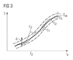
- the second embodiment which is reproduced in FIG. 3, shows an average ⁇ ok , which is independent of the defective piezo actuators.
- the mean value is formed in the same way as in FIG. This well-found mean value in FIG. 1 is stored as ⁇ ok . If a defective piezo actuator occurs at a later point in time, then a mean value ⁇ ok stored shortly before is used to define new limit values, which are identified by g + and g_. In contrast to the limit values from FIG. 1, these new limit values g + and g_ depend on the stored mean value ⁇ ok and on a new deviation ⁇ . This new deviation ⁇ is smaller than the deviation ⁇ .
- the curve C 3 of the third piezoelectric actuator exceeds the upper limit curve g + . Due to this exceeding of the limit value of this third piezoelectric actuator is detected as faulty. It should be noted that neither the new limit values g + and g_ nor the stored mean value ⁇ ok depend on the faulty third actuator which forms the curve C 3 .
Landscapes
- Engineering & Computer Science (AREA)
- Chemical & Material Sciences (AREA)
- Combustion & Propulsion (AREA)
- Mechanical Engineering (AREA)
- General Engineering & Computer Science (AREA)
- Combined Controls Of Internal Combustion Engines (AREA)
- Electrical Control Of Air Or Fuel Supplied To Internal-Combustion Engine (AREA)
- Fuel-Injection Apparatus (AREA)
Abstract
Description
Somit liegt der Erfindung die Aufgabe zugrunde, ein Verfahren zur Bestimmung von defekten Aktoren einer Brennkraftmaschine vorzustellen, das insbesondere frühzeitig auftretende Alterungseffekte von Aktoren zuverlässig erkennt.
- Figur 1
- die Temperaturabhängigkeit von den Piezoaktoren mit den erfindungsgemäß gebildeten Grenzwerten und dem erfindungsgemäß gebildeten Mittelwert;
- Figur 2
- die Temperaturabhängigkeiten der Kapazitäten der Piezoaktoren, wobei eine Kurve eines Piezos eine der Grenzen überschreitet;
- Figur 3
- die Temperaturabhängigkeiten der Kapazitäten der Piezoaktoren, wobei der Mittelwert unabhängig vom defekten Aktor ist.
Claims (12)
- Verfahren zur Bestimmung von defekten Aktoren einer Brennkraftmaschine mit mindestens einem Zylinder, wobei jeder Zylinder mindestens einen Aktor aufweist, umfassend folgende Schritte:a) Mittelwertbildung (µ) einer Messgröße (u) aller an den Zylindern vorhandenen Aktoren einer Art in Abhängigkeit von mindestens einem Parameter (p),b) Bildung einer Abweichung (µ), die vom Parameter (p) unabhängig ist,c) Bildung von unteren (G-) und oberen (G+) Grenzwerten, die von der Abweichung (µ) und vom Mittelwert (µ) abhängig sind,d) Einstufen eines Aktors als fehlerhaft, wenn einer der Grenzwerte (G-) oder (G+) durch einen Einzelwert (ui) der Messgröße (u) des Aktors überschritten wird.
- Verfahren nach Anspruch 1, dadurch gekennzeichnet, dass die Abweichung (µ) von der Anzahl der vorhandenen Aktoren einer Art abhängig ist.
- Verfahren nach mindestens einem der vorigen Ansprüche,
dadurch gekennzeichnet, dass der untere Grenzwert (G_) wie folgt gebildet wird: G_ = µ(p) - µ ;
wobei µ der Mittelwert der Messgröße u ist und vom Parameter p abhängt und µ für die Abweichung steht. - Verfahren nach mindestens einem der vorigen Ansprüche,
dadurch gekennzeichnet, dass der obere Grenzwert (G+) wie folgt gebildet wird: G+ = µ(p) + µ ;
wobei µ der Mittelwert der Messgröße u ist und vom Parameter p abhängt und µ für die Abweichung steht. - Verfahren nach mindestens einem der vorigen Ansprüche,
dadurch gekennzeichnet, dass der Parameter (p) gleich der Zeit (t) ist. - Verfahren nach mindestens einem der vorigen Ansprüche,
dadurch gekennzeichnet, dass der Parameter (p) gleich der Aktortemperatur (Ta) ist. - Verfahren nach mindestens einem der vorigen Ansprüche,
dadurch gekennzeichnet, dass die Mittelwertbildung der Messgröße (u) über den gesamten Parameterbereich abgespeichert wird, wenn über den gesamten Parameterbereich keiner der Einzelwerte (ui) der Messgröße (u) die beiden Grenzwerte (G_) und (G+) überschreitet. - Verfahren nach Anspruch 7, dadurch gekennzeichnet, dass nach dem Speichern des Mittelwerts (µok) der obere Grenzwert G+ wie folgt gebildet wird:
G+ = µok(p) + µ;
wobei µok der gespeicherte Mittelwert der Messgröße u ist und vom Parameter p abhängt und µ für die neue Abweichung steht, wobei die neue Abweichung µ kleiner als die Abweichung µ ist. - Verfahren nach Ansprüchen 7 und 8, dadurch gekennzeichnet, dass nach dem Speichern des Mittelwerts (µok) der untere Grenzwert (G_) wie folgt gebildet wird:
G_ = µok (p) - µ;
wobei µok der gespeicherte Mittelwert der Messgröße u ist und vom Parameter p abhängt und µ für die neue Abweichung steht, wobei die neue Abweichung µ kleiner als die Abweichung µ ist. - Verfahren nach mindestens einem der vorigen Ansprüche,
dadurch gekennzeichnet, dass eine Art eines Aktors ein Piezoelement ist und die Messgröße (u) die Aktorkapazität (C) ist. - Verfahren nach mindestens einem der Ansprüche 1 bis 9,
dadurch gekennzeichnet, dass eine Art eines Aktors eine Magnetspule ist und die Messgröße (u) die Aktorinduktivität ist. - Verfahren nach mindestens einem der vorigen Ansprüche,
dadurch gekennzeichnet, dass die Messgröße (u) der elektrische Widerstand des Aktors ist.
Applications Claiming Priority (2)
| Application Number | Priority Date | Filing Date | Title |
|---|---|---|---|
| DE102004012491 | 2004-03-15 | ||
| DE102004012491A DE102004012491B4 (de) | 2004-03-15 | 2004-03-15 | Verfahren zur Bestimmung von defekten Aktoren einer Brennkraftmaschine |
Publications (2)
| Publication Number | Publication Date |
|---|---|
| EP1577527A1 true EP1577527A1 (de) | 2005-09-21 |
| EP1577527B1 EP1577527B1 (de) | 2006-07-26 |
Family
ID=34833118
Family Applications (1)
| Application Number | Title | Priority Date | Filing Date |
|---|---|---|---|
| EP05100385A Expired - Lifetime EP1577527B1 (de) | 2004-03-15 | 2005-01-21 | Verfahren zur Bestimmung von defekten Aktoren einer Brennkraftmaschine |
Country Status (3)
| Country | Link |
|---|---|
| US (1) | US7146269B2 (de) |
| EP (1) | EP1577527B1 (de) |
| DE (2) | DE102004012491B4 (de) |
Cited By (3)
| Publication number | Priority date | Publication date | Assignee | Title |
|---|---|---|---|---|
| WO2009071393A1 (de) * | 2007-12-07 | 2009-06-11 | Robert Bosch Gmbh | Verfahren zum betreiben eines piezoelektrischen aktors |
| EP1843028A3 (de) * | 2006-04-07 | 2009-12-30 | Robert Bosch Gmbh | Verfahren zur Leckageprüfung eines ein Magnetventil aufweisenden Kraftstoffinjektors |
| EP3910101A1 (de) * | 2020-05-14 | 2021-11-17 | KARL MAYER STOLL R&D GmbH | Verfahren zur wartung einer kettenwirkmaschine |
Families Citing this family (2)
| Publication number | Priority date | Publication date | Assignee | Title |
|---|---|---|---|---|
| KR20100088676A (ko) * | 2007-11-21 | 2010-08-10 | 볼보 컨스트럭션 이큅먼트 에이비 | 센서를 보정하는 방법 |
| DE102013208528B3 (de) | 2013-05-08 | 2014-08-21 | Continental Automotive Gmbh | Verfahren zur Ermittlung der Öffnungs- und/oder Schließzeit der Düsennadel eines Einspritzventils |
Citations (2)
| Publication number | Priority date | Publication date | Assignee | Title |
|---|---|---|---|---|
| US6619245B1 (en) * | 1999-12-02 | 2003-09-16 | Nissan Motor Co., Ltd. | Failsafe control system and method for an electromagnetically driven valve |
| DE10236819A1 (de) * | 2002-08-10 | 2004-02-26 | Robert Bosch Gmbh | Verfahren, Computerprogramm, sowie Steuer- und/oder Regelgerät zum Betreiben eines Aktors mit einem kapazitiven Element, sowie Brennkraftmaschine |
Family Cites Families (3)
| Publication number | Priority date | Publication date | Assignee | Title |
|---|---|---|---|---|
| JPS60184948A (ja) * | 1984-03-02 | 1985-09-20 | Toyota Motor Corp | 電子制御デイ−ゼルエンジンの気筒別燃料噴射量学習制御方法 |
| DE19536109A1 (de) * | 1995-09-28 | 1997-04-03 | Bosch Gmbh Robert | Verfahren und Vorrichtung zur Überwachung eines Kraftstoffzumeßsystems |
| DE19845042C2 (de) * | 1998-09-30 | 2000-08-24 | Siemens Ag | Verfahren und Anordnung zur Diagnose eines kapazitiven Aktors |
-
2004
- 2004-03-15 DE DE102004012491A patent/DE102004012491B4/de not_active Expired - Fee Related
-
2005
- 2005-01-21 DE DE502005000046T patent/DE502005000046D1/de not_active Expired - Lifetime
- 2005-01-21 EP EP05100385A patent/EP1577527B1/de not_active Expired - Lifetime
- 2005-02-24 US US11/065,675 patent/US7146269B2/en not_active Expired - Fee Related
Patent Citations (2)
| Publication number | Priority date | Publication date | Assignee | Title |
|---|---|---|---|---|
| US6619245B1 (en) * | 1999-12-02 | 2003-09-16 | Nissan Motor Co., Ltd. | Failsafe control system and method for an electromagnetically driven valve |
| DE10236819A1 (de) * | 2002-08-10 | 2004-02-26 | Robert Bosch Gmbh | Verfahren, Computerprogramm, sowie Steuer- und/oder Regelgerät zum Betreiben eines Aktors mit einem kapazitiven Element, sowie Brennkraftmaschine |
Cited By (3)
| Publication number | Priority date | Publication date | Assignee | Title |
|---|---|---|---|---|
| EP1843028A3 (de) * | 2006-04-07 | 2009-12-30 | Robert Bosch Gmbh | Verfahren zur Leckageprüfung eines ein Magnetventil aufweisenden Kraftstoffinjektors |
| WO2009071393A1 (de) * | 2007-12-07 | 2009-06-11 | Robert Bosch Gmbh | Verfahren zum betreiben eines piezoelektrischen aktors |
| EP3910101A1 (de) * | 2020-05-14 | 2021-11-17 | KARL MAYER STOLL R&D GmbH | Verfahren zur wartung einer kettenwirkmaschine |
Also Published As
| Publication number | Publication date |
|---|---|
| DE102004012491A1 (de) | 2005-10-13 |
| US20050199051A1 (en) | 2005-09-15 |
| US7146269B2 (en) | 2006-12-05 |
| DE502005000046D1 (de) | 2006-09-07 |
| EP1577527B1 (de) | 2006-07-26 |
| DE102004012491B4 (de) | 2008-12-24 |
Similar Documents
| Publication | Publication Date | Title |
|---|---|---|
| EP1573188B1 (de) | Vorrichtung und verfahren zum erkennen von fehlern in einem kraftstoffeinspritzsystem | |
| WO2006094516A1 (de) | Verfahren zur steuerung und regelung einer brennkraftmaschine | |
| DE102006010194A1 (de) | Verfahren und Vorrichtung zum Betreiben der Glühkerzen einer selbstzündenden Brennkraftmaschine | |
| WO2001025625A1 (de) | Vorrichtung und verfahren zur zündung einer brennkraftmaschine | |
| DE112008001486T5 (de) | Verfahren zum Erkennen einer Kraftstoffeinspritzeinrichtung mit einer Fehlfunktion eines mehrzylindrigen Verbrennungsmotors | |
| DE102015214780A1 (de) | Verfahren zur Erkennung fehlerhafter Komponenten eines Kraftstoffeinspritzsystems | |
| DE112016004358T5 (de) | Kraftstoffeinspritzsteuervorrichtung für Maschine mit interner Verbrennung | |
| DE102004006554B3 (de) | Verfahren zur Zylindergleichstellung bezüglich der Kraftstoff-Einspritzmengen bei einer Brennkraftmaschine | |
| EP2076667B1 (de) | Verfahren und vorrichtung zur überwachung eines kraftstoffeinspritzsystems | |
| DE102009046417A1 (de) | Verfahren zur Erkennung eines Kraftstoffeintrags in das Schmieröl einer Brennkraftmaschine, insbesondere eines Kraftfahrzeugs | |
| EP1577527B1 (de) | Verfahren zur Bestimmung von defekten Aktoren einer Brennkraftmaschine | |
| DE102014208941A1 (de) | Verfahren zur Erkennung von an einem Einspritzsystem einer Brennkraftmaschine insbesondere eines Kraftfahrzeugs vorgenommenen Manipulationen | |
| DE102016119043B4 (de) | Lernverfahren zur Bestimmung des Einspritzverhaltens eines Kraftstoffinjektors und Verfahren zur Regelung von Einspritzmengen eines Kraftstoffinjektors an einem Verbrennungsmotor | |
| DE102018204450A1 (de) | Verfahren zum Prüfen einer variablen Ventilhubsteuerung eines Verbrennungsmotors | |
| DE10247942A1 (de) | Diagnoseverfahren für einen Motor mit variabler Kompression | |
| EP1278949B1 (de) | Verfahren zum betreiben eines kraftstoffversorgungssystems für eine brennkraftmaschine insbesondere eines kraftfahrzeugs | |
| DE102012211722A1 (de) | Verfahren zur Diagnose eines Bauteils, eines Systems oder einer Systemkomponente einer Brennkraftmaschine | |
| DE10100412B4 (de) | Verfahren zur Steuerung einer Brennkraftmaschine | |
| DE102011076287A1 (de) | Verfahren zum Betreiben einer Brennkraftmaschine | |
| DE102017206416B3 (de) | Verfahren zum Ermitteln eines dauereinspritzenden Brennraums, Einspritzsystem und Brennkraftmaschine mit einem solchen Einspritzsystem | |
| EP3234328B1 (de) | Verfahren und vorrichtung zur diagnose eines kraftstofffördersystems | |
| DE102005026054B4 (de) | Verfahren und Vorrichtung zur Überwachung der Funktionstüchtigkeit einer Ventilhub-Verstelleinrichtung einer Brennkraftmaschine in einer Kaltstartphase | |
| DE10338775B4 (de) | Diagnoseeinrichtung für einen Verbrennungsmotor | |
| DE102010025177A1 (de) | Diagnoseverfahren und Diagnosesystem zur Erkennung von Leckageströmen in Kraftfahrzeug-Hochdruckeinspritzanlagen | |
| DE102019122779A1 (de) | Modellbasierte Überwachung von Maschinenkomponenten |
Legal Events
| Date | Code | Title | Description |
|---|---|---|---|
| PUAI | Public reference made under article 153(3) epc to a published international application that has entered the european phase |
Free format text: ORIGINAL CODE: 0009012 |
|
| AK | Designated contracting states |
Kind code of ref document: A1 Designated state(s): AT BE BG CH CY CZ DE DK EE ES FI FR GB GR HU IE IS IT LI LT LU MC NL PL PT RO SE SI SK TR |
|
| AX | Request for extension of the european patent |
Extension state: AL BA HR LV MK YU |
|
| 17P | Request for examination filed |
Effective date: 20051021 |
|
| GRAP | Despatch of communication of intention to grant a patent |
Free format text: ORIGINAL CODE: EPIDOSNIGR1 |
|
| AKX | Designation fees paid |
Designated state(s): DE FR GB IT |
|
| GRAS | Grant fee paid |
Free format text: ORIGINAL CODE: EPIDOSNIGR3 |
|
| GRAA | (expected) grant |
Free format text: ORIGINAL CODE: 0009210 |
|
| AK | Designated contracting states |
Kind code of ref document: B1 Designated state(s): DE FR GB IT |
|
| PG25 | Lapsed in a contracting state [announced via postgrant information from national office to epo] |
Ref country code: IT Free format text: LAPSE BECAUSE OF FAILURE TO SUBMIT A TRANSLATION OF THE DESCRIPTION OR TO PAY THE FEE WITHIN THE PRESCRIBED TIME-LIMIT;WARNING: LAPSES OF ITALIAN PATENTS WITH EFFECTIVE DATE BEFORE 2007 MAY HAVE OCCURRED AT ANY TIME BEFORE 2007. THE CORRECT EFFECTIVE DATE MAY BE DIFFERENT FROM THE ONE RECORDED. Effective date: 20060726 |
|
| REG | Reference to a national code |
Ref country code: GB Ref legal event code: FG4D Free format text: NOT ENGLISH |
|
| GBT | Gb: translation of ep patent filed (gb section 77(6)(a)/1977) |
Effective date: 20060728 |
|
| REF | Corresponds to: |
Ref document number: 502005000046 Country of ref document: DE Date of ref document: 20060907 Kind code of ref document: P |
|
| ET | Fr: translation filed | ||
| PLBE | No opposition filed within time limit |
Free format text: ORIGINAL CODE: 0009261 |
|
| STAA | Information on the status of an ep patent application or granted ep patent |
Free format text: STATUS: NO OPPOSITION FILED WITHIN TIME LIMIT |
|
| 26N | No opposition filed |
Effective date: 20070427 |
|
| PGRI | Patent reinstated in contracting state [announced from national office to epo] |
Ref country code: IT Effective date: 20090301 |
|
| REG | Reference to a national code |
Ref country code: FR Ref legal event code: TP |
|
| REG | Reference to a national code |
Ref country code: GB Ref legal event code: 732E Free format text: REGISTERED BETWEEN 20110825 AND 20110831 |
|
| REG | Reference to a national code |
Ref country code: FR Ref legal event code: PLFP Year of fee payment: 12 |
|
| REG | Reference to a national code |
Ref country code: FR Ref legal event code: PLFP Year of fee payment: 13 |
|
| REG | Reference to a national code |
Ref country code: FR Ref legal event code: PLFP Year of fee payment: 14 |
|
| PGFP | Annual fee paid to national office [announced via postgrant information from national office to epo] |
Ref country code: GB Payment date: 20180119 Year of fee payment: 14 |
|
| PGFP | Annual fee paid to national office [announced via postgrant information from national office to epo] |
Ref country code: IT Payment date: 20180129 Year of fee payment: 14 Ref country code: FR Payment date: 20180119 Year of fee payment: 14 |
|
| GBPC | Gb: european patent ceased through non-payment of renewal fee |
Effective date: 20190121 |
|
| PG25 | Lapsed in a contracting state [announced via postgrant information from national office to epo] |
Ref country code: FR Free format text: LAPSE BECAUSE OF NON-PAYMENT OF DUE FEES Effective date: 20190131 |
|
| PG25 | Lapsed in a contracting state [announced via postgrant information from national office to epo] |
Ref country code: GB Free format text: LAPSE BECAUSE OF NON-PAYMENT OF DUE FEES Effective date: 20190121 |
|
| PG25 | Lapsed in a contracting state [announced via postgrant information from national office to epo] |
Ref country code: IT Free format text: LAPSE BECAUSE OF FAILURE TO SUBMIT A TRANSLATION OF THE DESCRIPTION OR TO PAY THE FEE WITHIN THE PRESCRIBED TIME-LIMIT Effective date: 20190121 |
|
| REG | Reference to a national code |
Ref country code: DE Ref legal event code: R084 Ref document number: 502005000046 Country of ref document: DE |
|
| REG | Reference to a national code |
Ref country code: DE Ref legal event code: R081 Ref document number: 502005000046 Country of ref document: DE Owner name: VITESCO TECHNOLOGIES GMBH, DE Free format text: FORMER OWNER: CONTINENTAL AUTOMOTIVE GMBH, 30165 HANNOVER, DE |
|
| PGFP | Annual fee paid to national office [announced via postgrant information from national office to epo] |
Ref country code: DE Payment date: 20210131 Year of fee payment: 17 |
|
| REG | Reference to a national code |
Ref country code: DE Ref legal event code: R081 Ref document number: 502005000046 Country of ref document: DE Owner name: VITESCO TECHNOLOGIES GMBH, DE Free format text: FORMER OWNER: VITESCO TECHNOLOGIES GMBH, 30165 HANNOVER, DE |
|
| REG | Reference to a national code |
Ref country code: DE Ref legal event code: R119 Ref document number: 502005000046 Country of ref document: DE |
|
| PG25 | Lapsed in a contracting state [announced via postgrant information from national office to epo] |
Ref country code: DE Free format text: LAPSE BECAUSE OF NON-PAYMENT OF DUE FEES Effective date: 20220802 |