EP1577249A2 - Safety monitoring for elevator cab - Google Patents
Safety monitoring for elevator cab Download PDFInfo
- Publication number
- EP1577249A2 EP1577249A2 EP05002269A EP05002269A EP1577249A2 EP 1577249 A2 EP1577249 A2 EP 1577249A2 EP 05002269 A EP05002269 A EP 05002269A EP 05002269 A EP05002269 A EP 05002269A EP 1577249 A2 EP1577249 A2 EP 1577249A2
- Authority
- EP
- European Patent Office
- Prior art keywords
- elevator car
- elevator
- predetermined
- microprocessors
- speed
- Prior art date
- Legal status (The legal status is an assumption and is not a legal conclusion. Google has not performed a legal analysis and makes no representation as to the accuracy of the status listed.)
- Granted
Links
Images


Classifications
-
- B—PERFORMING OPERATIONS; TRANSPORTING
- B66—HOISTING; LIFTING; HAULING
- B66B—ELEVATORS; ESCALATORS OR MOVING WALKWAYS
- B66B5/00—Applications of checking, fault-correcting, or safety devices in elevators
- B66B5/02—Applications of checking, fault-correcting, or safety devices in elevators responsive to abnormal operating conditions
- B66B5/04—Applications of checking, fault-correcting, or safety devices in elevators responsive to abnormal operating conditions for detecting excessive speed
- B66B5/06—Applications of checking, fault-correcting, or safety devices in elevators responsive to abnormal operating conditions for detecting excessive speed electrical
Definitions
- the invention relates to a security monitoring device for a Elevator car.
- a device for delay control intended.
- the elevator shaft are located at the top of the pit and on the mechanical side Buffers that serve to decelerate the elevator car in an emergency.
- the speed of the elevator car a does not exceed the predetermined limit.
- the Braking device for the elevator car when the limit exceeded will be started soon enough for a sufficient deceleration, the takes place in accordance with a braking ramp, it can be done so that the buffer the Residual braking can take over.
- the device arranged for delay control at the appropriate location in the shaft electromechanical switch comprising, with a safety relay module coupled, and when they are reached in an elevator ride in the direction of Buffer and exceeding the limit for the speed Cab brakes triggered and simultaneously the drive is turned off.
- a device for retracting and if necessary to provide readjustments with open doors with a Bridging device for electromechanical door contacts that monitor whether the shaft door is closed.
- a Bridging device for electromechanical door contacts that monitor whether the shaft door is closed.
- Such mechanically based safety devices do not allow any continuous monitoring, but only a one-off.
- EP 0 694 792 B1 and EP 1 030 190 B1 is a Device for detecting the position of an elevator car is known, wherein in the Elevator shaft a sound signal conductor with predetermined, uniform Sound propagation speed is while the elevator car a Signal coupler for coupling a clocked sound signal in the Having sound signal conductor. At both ends of the sound signal conductor are Signal output coupler arranged with an evaluation unit for determining the Duration difference of the coupled-in sound signal from the coupling point to the signal extractors and for generating a for the current position of the Elevator car in the elevator shaft representative signal are connected.
- the object of the invention is to provide a security monitoring device for to create an elevator car that provides continuous safety monitoring allows.
- Fig. 1 shows a block diagram of an elevator monitoring and control with a position detection device for an elevator car.
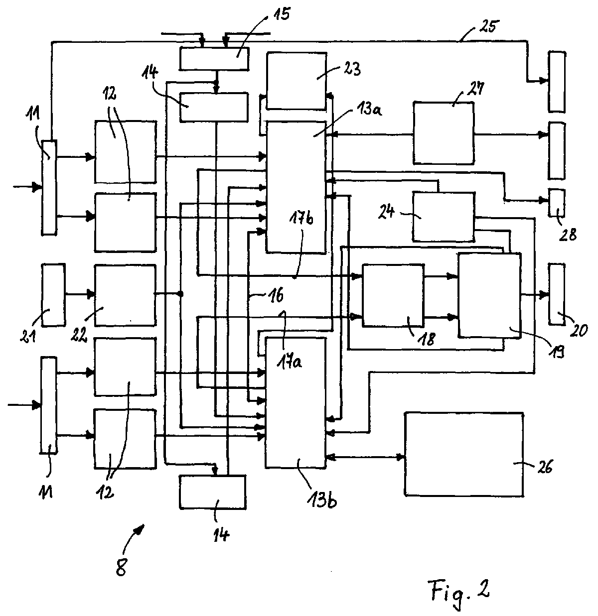
- FIG. 2 shows a block diagram of a security monitoring device for the elevator control of Fig. 1.
- Fig. 3 shows a velocity-time diagram as a motion profile for a Elevator car.
- a Position detection device for one along an elevator shaft A means a traction drive D movable elevator car 1 is the latter with a Signal coupler 2 provided, which serves to sound signals in a Sound signal conductor 3 with predetermined, uniform Sound propagation speed, which along the Elevator shaft extends. In both end regions of the sound signal conductor. 3 There is in each case a receiver unit 4a or 4b, which has a signal output coupler 5 and an evaluation unit 6 include. One of the evaluation units 6 supplies Trigger signals corresponding to a predetermined time grid to the signal coupler 2 of the elevator car 1, which is the coupling of a sound signal in the sound signal conductor 3 trigger, and to the other evaluation unit 6, so this also knows the respective triggering time.
- the signal coupler 2 both Evaluation 6 tell the time of coupling the sound signal, so that both evaluation units 6 each separately from the predetermined, uniform sound propagation velocity and signal transit time the Can calculate the position of the elevator car 1.
- the outputs 7a, 7b of the evaluation units 6 serve as inputs for a Safety monitoring device 8.
- the latter communicates with a Elevator control 9, via which the driving profile of the elevator car 1 is predetermined, and a safety circuit 10 for shutting off the elevator drive.
- the safety monitoring device 8 comprises two bushes 11, with to which the outputs 7a, 7b of the evaluation units 6 are connected. About one Interface 12, the position signals of the evaluation units 6, the corresponding the trigger signals are supplied in a predetermined time frame, respectively a microprocessor 13 a and 13 b given, for each one Power supply unit 14 is provided. The latter are connected to a network and connected to an emergency battery power supply 15 connected. At this dual-channel security monitoring, the microprocessors 13a communicate 13b for the purpose of mutual control over a line 16 with each other, whereby a crosswise data comparison, which also synchronizes the two Microprocessors 13a, 13b can be used.
- microprocessors 13a, 13b can be speed and acceleration and optionally one jerky movement of the elevator car 1 location dependent notice and currently compare with a given motion profile.
- an amplifier 18, which may also simultaneously as Comparator can act only to from both microprocessors 13a, 13b Maschinenminalten be present, the same output signals to be driven, the a safety relay stage 19 is actuated, the - in response to the microprocessors 13a, 13b - on the elevator control 9 and the safety circuit 10th acting with an appropriate jack 20 of the Safety monitoring device 8 is connected.
- Microprocessor 13a and 13b may optionally also have two interfaces 12 be provided to receive signals from different types of encoders to be able to process.
- a curve K1 is shown by way of example, which represents the driving profile of an elevator car 1 between two further floors, which is predetermined by the elevator control 9.
- the curve K1 has at the time of departure starting from a starting ramp up to a rated speed v nenn and from the latter to the arrival time a braking ramp.
- the curve K2, also shown by way of example in FIG. 3, is the driving profile between two closely adjacent storeys, the nominal speed vnom not being reached.
- the microprocessors 13a, 13b simultaneously or within a time window emit a corresponding signal which causes the traction drive to stop via the safety relay stage 19.
- a device for limiting the speed of the elevator car 1 is formed, which not only reacts to a predetermined exceeding of vnenn , but is a speed profile and thus more responsive.
- the safety monitoring device 8 can be used at the same time as a device for deceleration control, by then, if it is determined at a certain point in the elevator shaft A, that the current speed of the elevator car 1 a predetermined amount (not necessarily V nominal) exceeds, so that braking is no longer ensured by located in the elevator shaft a buffer, the microprocessors 13a, 13b leave the same time or within a time window, a corresponding signal to the safety relay stage 19 a stopping of the Travel drive and triggering the braking device causes. - As a result, smaller sized buffer can be used, or you can completely do without it.
- the security monitoring device 8 as a control for retractable with open doors usable.
- a request signal of a user are present from the elevator car 1 or from the corresponding floor, about via a socket 21 of the safety monitoring device 8 and an interface 22 is given to the microprocessors 13a, 13b. If the request signal arrives too late because the user has pressed the corresponding button too late, the speed is too high and the microprocessors 13a, 13b are not giving Bridging signal for the door contacts off, so that the doors open either can not be started before the standstill of the elevator car 1 or the Elevator car 1 even passes through.
- the security monitoring device 8 also for Creation of a virtual shelter on the head and / or pit side elevator shaft A, for example, when carrying out work in this Be used area, i. that at a corresponding request signal the route of the elevator car 1 is limited accordingly, so that a Intrusion into the virtual shelter is prevented.
- microprocessors 13a, 13b can also be used in Reference to the acceleration and the derivative thereof (the latter for evaluation of jerky movements).
- a diagnostic LED display 23 may be connected to the microprocessors 13a, 13b be coupled.
- the safety relay 19 can also have its own Power supply unit 24, in turn, from the microprocessors 13a, 13b is monitored.
- the respective position of the elevator car 1 is either from the position detection device via a line 25 or one of the Microprocessors 13 a, 13 b transmitted to the elevator controller 9.
- Over a Input device 26 in the form of a keyboard or the like. can the microprocessors 13a, 13b required data are entered. However, the data can also are received via the line 25 from the elevator controller 9.
- an output 28 may be present, which is the bottom flush of elevator car 1 and floor displays.
Landscapes
- Maintenance And Inspection Apparatuses For Elevators (AREA)
- Indicating And Signalling Devices For Elevators (AREA)
- Electric Propulsion And Braking For Vehicles (AREA)
- Forklifts And Lifting Vehicles (AREA)
Abstract
Die Erfindung betrifft eine Sicherheitsüberwachungseinrichtung für eine in einem
Aufzugsschacht (A) mittels eines Fahrantriebs (D) über eine Aufzugssteuerung (9)
verfahrbare Aufzugskabine (1), deren momentane Position mittels einer
Positionserfassungseinrichtung erfaßbar ist, die zwei unabhängig voneinander
erstellte Positionssignale in einem vorbestimmten Zeitraster liefert, mit einer
zweikanaligen Auswertung der Positionssignale durch jeweils einen Mikroprozessor
(13a, 13b) zur ortsabhängigen, momentanen Bestimmung der Geschwindigkeit der
Aufzugskabine (1 ) und zum Vergleichen mit einem vorgegebenen Bewegungsprofil,
wobei bei Überschreiten eines vorbestimmten momentanen
Geschwindigkeitssollwertes ein über eine Sicherheitsrelaisstufe (19) abgebbares
Auslösesignal erzeugbar ist.
Description
Die Erfindung betrifft eine Sicherheitsüberwachungseinrichtung für eine Aufzugskabine.The invention relates to a security monitoring device for a Elevator car.
Bei Aufzügen ist es üblich, Sicherheitsfunktionen vorzusehen, um das Fahrverhalten der Aufzugskabine (oder des Fahrkorbs) zu überwachen, damit Unfälle vermieden werden können.In elevators, it is common to provide safety features to the To monitor the driving behavior of the elevator car (or the car) so that Accidents can be avoided.
Hierzu ist beispielsweise eine Einrichtung zur Verzögerungskontrolle vorgesehen. Im Aufzugsschacht befinden sich gruben- und kopfseitig mechanische Puffer, die dazu dienen, die Aufzugskabine im Notfall abzubremsen. Allerdings ist dafür Voraussetzung, daß die Geschwindigkeit der Aufzugskabine einen vorbestimmten Grenzwert nicht überschreitet. Um dies zu erreichen, muß die Bremseinrichtung für die Aufzugskabine dann, wenn der Grenzwert überschritten wird, früh genug in Gang gesetzt werden, damit eine genügende Abbremsung, die entsprechend einer Bremsrampe stattfindet, derart erfolgen kann, daß die Puffer die Restabbremsung übernehmen können. Hierzu ist es bekannt, daß die Einrichtung zur Verzögerungskontrolle an entsprechender Stelle im Schacht angeordnete elektromechanische Schalter umfaßt, die mit einem Sicherheitsrelaisbaustein gekoppelt sind, und bei deren Erreichen bei einer Aufzugsfahrt in Richtung der Puffer und Überschreiten des Grenzwertes für die Geschwindigkeit die Kabinenbremsung ausgelöst und gleichzeitig der Antrieb abgestellt wird.For this purpose, for example, a device for delay control intended. In the elevator shaft are located at the top of the pit and on the mechanical side Buffers that serve to decelerate the elevator car in an emergency. However, that is for that condition that the speed of the elevator car a does not exceed the predetermined limit. To achieve this, the Braking device for the elevator car when the limit exceeded will be started soon enough for a sufficient deceleration, the takes place in accordance with a braking ramp, it can be done so that the buffer the Residual braking can take over. For this purpose it is known that the device arranged for delay control at the appropriate location in the shaft electromechanical switch comprising, with a safety relay module coupled, and when they are reached in an elevator ride in the direction of Buffer and exceeding the limit for the speed Cab brakes triggered and simultaneously the drive is turned off.
Ferner ist es bekannt, eine mechanische Einrichtung zur Geschwindigkeitsbegrenzung der Aufzugskabine vorzusehen, die dazu dient, bei Überschreiten eines vorbestimmten Sollwertes der Geschwindigkeit der Aufzugskabine ein an der Aufzugskabine befindliches Bremssystem Fliehkraft gesteuert auszulösen.It is also known to provide a mechanical device for Provide speed limit of the elevator car, which serves, at Exceeding a predetermined setpoint of the speed of Elevator car a centrifugal force located on the elevator car controlled to trigger.
Außerdem ist es bekannt, eine Einrichtung zum Einfahren und gegebenenfalls Nachstellen mit offenen Türen vorzusehen, wobei eine Überbrückungseinrichtung für elektromechanische Türkontakte, die überwachen, ob die Schachttür geschlossen ist, vorgesehen ist. - Bei hohen Gebäuden mit sehr vielen Stockwerken ist zum Einsparen von Fahrzeit vorgesehen, daß die Türen sich bereits ab einer bestimmten Distanz vor Erreichen der gewählten Stockwerksposition, d.h. beim Einfahren in letztere, anfangen zu öffnen, so daß sie bei Erreichen dieser Position geöffnet sind. - Wenn eine größere Last in eine Aufzugskabine eingebracht oder daraus entfernt wird, bewegt sich der Boden der Aufzugskabine in Bezug auf das Bodenniveau des entsprechenden Stockwerks, an dem die Aufzugskabine hält. Damit ein Nachstellen zum Fluchten der Bodenniveaus von Aufzugskabine und Stockwerk bei geöffneten Türen stattfinden kann, ist ebenfalls eine entsprechende Überbrückung der Türkontakte notwendig. - Entsprechendes trifft für den Fall zu, daß eine Bodenhöhenanpassung der Aufzugskabine an eine Beladungsrampenhöhe etwa eines LKW's vorgenommen werden soll, sogenannte Rampenfahrtsteuerung.It is also known, a device for retracting and if necessary to provide readjustments with open doors, with a Bridging device for electromechanical door contacts that monitor whether the shaft door is closed, is provided. - For tall buildings with a lot many floors is provided to save driving time that the doors themselves already at a certain distance before reaching the chosen one Floor position, i. when entering the latter, start to open, so that they are open when reaching this position. - If a larger load in one The elevator car is moved or removed, the bottom moves Elevator car in relation to the floor level of the corresponding floor, at which holds the elevator car. Thus an adjustment to the alignment of the soil levels elevator car and floor can be held with the doors open also a corresponding bridging the door contacts necessary. - The same applies in the event that a floor height adjustment of Elevator car to a loading ramp height made about a truck should be, so-called ramp control.
Derartige mechanisch basierte Sicherheitseinrichtungen erlauben keine kontinuierliche Überwachung, sondern nur eine punktuelle.Such mechanically based safety devices do not allow any continuous monitoring, but only a one-off.
Beispielsweise aus EP 0 694 792 B1 und EP 1 030 190 B1 ist eine Einrichtung zur Positionserfassung einer Aufzugskabine bekannt, wobei sich in dem Aufzugsschacht ein Schallsignalleiter mit vorbestimmter, gleichmäßiger Schallausbreitungsgeschwindigkeit befindet, während die Aufzugskabine einen Signaleinkoppler zum Einkoppeln eines getakteten Schallsignals in den Schallsignalleiter aufweist. An beiden Enden des Schallsignalleiters sind Signalauskoppler angeordnet, die mit einer Auswerteeinheit zur Bestimmung der Laufzeitdifferenz des eingekoppelten Schallsignals von der Einkopplungsstelle zu den Signalauskopplern und zur Erzeugung eines für die momentane Position der Aufzugskabine im Aufzugsschacht repräsentativen Signals verbunden sind.For example, from EP 0 694 792 B1 and EP 1 030 190 B1 is a Device for detecting the position of an elevator car is known, wherein in the Elevator shaft a sound signal conductor with predetermined, uniform Sound propagation speed is while the elevator car a Signal coupler for coupling a clocked sound signal in the Having sound signal conductor. At both ends of the sound signal conductor are Signal output coupler arranged with an evaluation unit for determining the Duration difference of the coupled-in sound signal from the coupling point to the signal extractors and for generating a for the current position of the Elevator car in the elevator shaft representative signal are connected.
Aufgabe der Erfindung ist es, eine Sicherheitsüberwachungseinrichtung für eine Aufzugskabine zu schaffen, die eine kontinuierliche Sicherheitsüberwachung ermöglicht.The object of the invention is to provide a security monitoring device for to create an elevator car that provides continuous safety monitoring allows.
Diese Aufgabe wird entsprechend den Merkmalen des Anspruchs 1 gelöst.This object is achieved according to the features of claim 1.
Infolge einer zweikanaligen Auswertung von Positionssignalen der Aufzugskabine durch jeweils einen Mikroprozessor wird hierbei ortsabhängig momentan die Geschwindigkeit und gegebenenfalls die Beschleunigung (sowie eventuell deren Ableitung) der Aufzugskabine bestimmt und mit einem vorgegebenen Bewegungsprofil verglichen, wobei bei Überschreiten eines vorbestimmten Sollwertes ein Auslösesignal erzeugbar ist, so daß die Sicherheitsüberwachungseinrichtung im entsprechenden Störungsfall für eine oder mehrere der eingangs bzw. später genannten Sicherheitsfunktionen einsetzbar ist. Hierbei ist eine kontinuierliche Kontrolle nicht nur in Bezug auf einen bestimmten Sollwert, sondern in Bezug auf eine Sollkurve möglich.As a result of a two - channel evaluation of position signals of the Elevator cabin by a microprocessor is in each case location-dependent currently the speed and possibly the acceleration (as well possibly its derivative) of the elevator car determined and with a predefined movement profile, wherein when exceeding a predetermined setpoint, a trigger signal can be generated, so that the Safety monitoring device in the corresponding fault case for one or several of the above or later mentioned security functions can be used. Here is a continuous control not only in relation to a particular Setpoint, but with respect to a setpoint curve possible.
Weitere Ausgestaltungen der Erfindung sind der nachfolgenden Beschreibung und den Unteransprüchen zu entnehmen.Further embodiments of the invention are the following Description and the dependent claims.
Die Erfindung wird nachstehend anhand eines in den beigefügten Abbildungen dargestellten Ausführungsbeispiels näher erläutert.The invention is described below with reference to one of the attached Illustrated illustrations illustrated embodiment.
Fig. 1 zeigt ein Blockschaltbild einer Aufzugsüberwachung und -steuerung mit einer Positionserfassungseinrichtung für eine Aufzugskabine.Fig. 1 shows a block diagram of an elevator monitoring and control with a position detection device for an elevator car.
Fig. 2 zeigt ein Blockschaltbild einer Sicherheitsüberwachungseinrichtung für die Aufzugssteuerung von Fig. 1.FIG. 2 shows a block diagram of a security monitoring device for the elevator control of Fig. 1.
Fig. 3 zeigt ein Geschwindigkeits-Zeit-Diagramm als Bewegungsprofil für eine Aufzugskabine.Fig. 3 shows a velocity-time diagram as a motion profile for a Elevator car.
Bei der in Fig. 1 dargestellten Aufzugsüberwachung und -steuerung ist eine
Positionserfassungseinrichtung für eine längs eines Aufzugsschachtes A mittels
eines Fahrantriebs D verfahrbare Aufzugskabine 1 ist letztere mit einem
Signaleinkoppler 2 versehen, der dazu dient, Schallsignale in einen
Schallsignalleiter 3 mit vorbestimmter, gleichmäßiger
Schallausbreitungsgeschwindigkeit einzukoppeln, der sich entlang des
Aufzugsschachtes erstreckt. In beiden Endbereichen des Schallsignalleiters 3
befindet sich jeweils eine Empfängereinheit 4a bzw. 4b, die einen Signalauskoppler
5 und eine Auswerteeinheit 6 umfassen. Eine der Auswerteeinheiten 6 liefert
Triggersignale entsprechend einem vorbestimmten Zeitraster an den Signaleinkoppler
2 der Aufzugskabine 1, die das Einkoppeln eines Schallsignals in den Schallsignalleiter
3 auslösen, und an die andere Auswerteeinheit 6, damit diese ebenfalls
den jeweiligen Auslösezeitpunkt kennt. Aus der Laufzeit des eingekoppelten
Schallsignals entlang des Schallsignalleiters 3 vom Schallsignaleinkoppler 2 zu den
beiden Schallsignalauskopplern 5 und der Schallausbreitungsgeschwindigkeit im
Schallsignalleiter 3 berechnen die Auswerteeinheiten 6 jeweils separat und
redundant den Einkopplungsort und damit die Position der Aufzugskabine 1.In the elevator monitoring and control shown in Fig. 1 is a
Position detection device for one along an elevator shaft A means
a traction drive D movable elevator car 1 is the latter with a
Stattdessen kann aber auch der Signaleinkoppler 2 beiden
Auswerteeinheiten 6 den Zeitpunkt des Einkoppeln des Schallsignals mitteilen, so
daß beide Auswerteeinheiten 6 jeweils separat aus der vorbestimmten,
gleichmäßigen Schallausbreitungsgeschwindigkeit und der Signallaufzeit die
Position der Aufzugskabine 1 berechnen können.Instead, however, the signal coupler 2 both
Die Ausgänge 7a, 7b der Auswerteeinheiten 6 dienen als Eingänge für eine
Sicherheitsüberwachungseinrichtung 8. Letztere kommuniziert mit einer
Aufzugssteuerung 9, über die das Fahrprofil der Aufzugskabine 1 vorgegeben ist,
und einem Sicherheitskreis 10 zum Abschalten des Aufzugsantriebs.The
Die Sicherheitsüberwachungseinrichtung 8 umfaßt zwei Buchsen 11, mit
denen die Ausgänge 7a, 7b der Auswerteeinheiten 6 verbunden sind. Über ein
Interface 12 werden die Positionssignale der Auswerteeinheiten 6, die entsprechend
den Triggersignalen in einem vorbestimmten Zeitraster geliefert werden, jeweils auf
einen Mikroprozessor 13a bzw. 13b gegeben, für die jeweils eine
Stromversorgungseinheit 14 vorgesehen ist. Letztere sind an ein netzbetriebenes
und mit einer Notbatterie gekoppeltes Netzteil 15 angeschlossen. Bei dieser
zweikanaligen Sicherheitsüberwachung kommunizieren die Mikroprozessoren 13a,
13b zwecks gegenseitiger Kontrolle über eine Leitung 16 miteinander, wodurch ein
kreuzweiser Datenvergleich stattfindet, der auch zur Synchronisierung der beiden
Mikroprozessoren 13a, 13b genutzt werden kann. Mittels der Mikroprozessoren 13a,
13b läßt sich Geschwindigkeit und Beschleunigung sowie gegebenenfalls eine
ruckartige Bewegung der Aufzugskabine 1 ortsabhängig momentan feststellen und
mit einem vorgegebenen Bewegungsprofil vergleichen. Im Gefahrenfall kann über
Leitungen 17a, 17b ein Verstärker 18, der eventuell gleichzeitig auch als
Komparator wirken kann, um nur bei von beiden Mikroprozessoren 13a, 13b
vorliegenden gleichen Ausgangssignalen durchzuschalten, angesteuert werden, der
eine Sicherheitsrelaisstufe 19 betätigt, die - unter Rückmeldung an die Mikroprozessoren
13a, 13b - auf die Aufzugssteuerung 9 und den Sicherheitskreis 10
einwirkt, die mit einer ent-sprechenden Buchse 20 der
Sicherheitsüberwachungseinrichtung 8 verbunden ist.The
Für die Signalübertragung von der jeweiligen Buchse 11 zum zugehörigen
Mikroprozessor 13a bzw. 13b können gegebenenfalls auch zwei Interfaces 12
vorgesehen sein, um Signale von unterschiedlichen Typen von Weggebern
verarbeiten zu können.For the signal transmission from the
In Fig. 3, die ein Geschwindigkeits-Zeit-Diagramm darstellt, ist beispielhaft
eine Kurve K1 dargestellt, die das Fahrprofil einer Aufzugskabine 1 zwischen zwei
weiter entfernten Stockwerken darstellt, die von der Aufzugssteuerung 9
vorgegeben wird. Die Kurve K1 besitzt beim Abfahrzeitpunkt beginnend eine
Anfahrrampe bis zu einer Nenngeschwindigkeit vnenn und von letzterer bis zum
Ankunftszeitpunkt eine Bremsrampe. - Bei der ebenfalls in Fig. 3 beispielhaft
dargestellten Kurve K2 handelt es sich um das Fahrprofil zwischen zwei nahe
benachbarten Stockwerken, wobei die Nenngeschwindigkeit vnenn nicht erreicht wird.In FIG. 3, which illustrates a speed-time diagram, a curve K1 is shown by way of example, which represents the driving profile of an elevator car 1 between two further floors, which is predetermined by the
Wenn die momentane Geschwindigkeit der Aufzugskabine 1 aufgrund einer
Störung um einen vorbestimmten Betrag, der sich prozentual oder nach einer
Sollkurve S1 (hier für die Kurve K1) bestimmt, überschritten wird, befindet sich die
Geschwindigkeit in einem verbotenen Bereich. Dies führt dazu, daß die
Mikroprozessoren 13a, 13b gleichzeitig oder innerhalb eines Zeitfensters ein
entsprechendes Signal abgeben, das über die Sicherheitsrelaisstufe 19 ein
Stillsetzen des Fahrantriebs bewirkt. Hierdurch wird eine Einrichtung zur
Geschwindigkeitsbegrenzung der Aufzugskabine 1 gebildet, die nicht nur auf ein
vorbestimmtes Überschreiten von vnenn reagiert, sondern eines
Geschwindigkeitsprofils und somit entsprechend reaktionsfähiger ist.If the current speed of the elevator car 1 is exceeded due to a disturbance by a predetermined amount, which determines in percentage or after a setpoint curve S1 (here for the curve K1), the speed is in a prohibited area. As a result, the
Da durch die Mikroprozessoren 13a, 13b die Geschwindigkeit einer
bestimmten Position der Aufzugskabine 1 zugeordnet wird, kann die
Sicherheitsüberwachungseinrichtung 8 zugleich als Einrichtung zur
Verzögerungskontrolle verwendet werden, indem dann, wenn an einer bestimmten
Stelle im Aufzugsschacht A festgestellt wird, daß die momentane Geschwindigkeit
der Aufzugskabine 1 einen vorbestimmten Betrag (nicht notwendigerweise vnenn)
überschreitet, so daß ein Abbremsen durch im Aufzugsschacht A befindliche Puffer
nicht mehr gewährleistet ist, die Mikroprozessoren 13a, 13b gleichzeitig oder
innerhalb eines Zeitfensters ein entsprechendes Signal abgeben, das über die
Sicherheitsrelaisstufe 19 ein Stillsetzen des Fahrantriebs und ein Auslösen der
Bremseinrichtung bewirkt. - Hierdurch können kleiner dimensionierte Puffer zur
Anwendung gelangen, oder man kann ganz auf diese verzichten.Since the speed of a specific position of the elevator car 1 is assigned by the
Gleichzeitig ist die Sicherheitsüberwachungseinrichtung 8 als Kontrolle für
das Einfahren mit offenen Türen verwendbar. Hierzu ist wiederum die momentane
Geschwindigkeit der Aufzugskabine 1 und deren Position, d.h. deren Abstand zum
nächsten Halt, zu kontrollieren. Hierzu muß ein Anforderungssignal eines Benutzers
aus der Aufzugskabine 1 oder vom entsprechenden Stockwerk vorliegen, das etwa
über eine Buchse 21 der Sicherheitsüberwachungseinrichtung 8 und ein Interface
22 an die Mikroprozessoren 13a, 13b gegeben wird. Wenn das Anforderungssignal
zu spät eintrifft, weil der Benutzer den entsprechenden Knopf zu spät betätigt hat,
ist die Geschwindigkeit zu groß und die Mikroprozessoren 13a, 13b geben kein
Überbrückungssignal für die Türkontakte ab, so daß das Öffnen der Türen entweder
nicht vor dem Stillstand der Aufzugskabine 1 begonnen werden kann oder die
Aufzugskabine 1 sogar durchfährt.At the same time, the
Entsprechendes gilt für das Nachstellen der Aufzugskabine 1 bei offenen Türen zum bodenseitigen Nivellieren von Aufzugskabine 1 und Stockwerk. Hierbei ist wiederum durch die Sicherheitsüberwachungseinrichtung 8 ein Überbrückungssignal für die Türkontakte abzugeben, damit die Aufzugskabine 1 bei offenen Türen entsprechend verfahren werden kann.The same applies to the readjustment of the elevator car 1 when open Doors for floor leveling of elevator car 1 and floor. in this connection is in turn by the security monitoring device 8 a Give over bridging signal for the door contacts, so that the elevator car 1 at open doors can be moved accordingly.
Bei Rampenfahrtsteuerung muß zunächst ein entsprechendes
Berechtigungssignal etwa mittels eines schlüsselbetätigbaren Schalters vorhanden
sein, so daß wiederum durch die Sicherheitsüberwachungseinrichtung 8 ein
Überbrückungssignal für die Türkontakte abgegeben wird, so daß das Verfahren der
Aufzugskabine 1 innerhalb eines vorbestimmten Distanzintervalls ermöglicht wird,
das über die Position der Aufzugskabine 1 von den Mikroprozessoren 13a, 13b
kontrolliert wird. An den Grenzen des Distanzintervalls wird dann ein Signal zum
Stillsetzen des Fahrantriebs D erzeugt.When ramp control must first a corresponding
Authorization signal about by means of a key-operated switch available
be, so that in turn by the security monitoring device 8 a
Bridging signal is issued for the door contacts, so that the process of
Elevator car 1 is allowed within a predetermined distance interval,
that about the position of the elevator car 1 from the
Gegebenenfalls kann die Sicherheitsüberwachungseinrichtung 8 auch zur
Schaffung eines virtuellen Schutzraums etwa an der Kopf- und/oder Grubenseite
des Aufzugsschachtes A zum Beispiel bei der Vornahme von Arbeiten in diesem
Bereich verwendet werden, d.h. daß bei einem entsprechenden Anforderungssignal
die Fahrtstrecke der Aufzugskabine 1 entsprechend begrenzt wird, so daß ein
Eindringen in den virtuellen Schutzraum verhindert wird.Optionally, the
Entsprechend können die Mikroprozessoren 13a, 13b zusätzlich auch in
Bezug auf die Beschleunigung und die Ableitung hiervon (letzteres zur Bewertung
von ruckartigen Bewegungen) eingesetzt werden.Correspondingly, the
Auch die Funktion von entsprechenden Notendschaltern für die Fahrtstrecke
der Aufzugskabine 1 oder sonstigen Sicherheitsschaltern kann ebenso von der
Sicherheitsüberwachungseinrichtung 8 übernommen werden.Also the function of appropriate emergency limit switches for the route
the elevator car 1 or other safety switches can also from the
Gegebenenfalls erfolgt durch die Auswerteeinheiten 6 nur eine
entsprechende Signalaufbereitung für die Positionssignale, während die
Mikroprozessoren 13a, 13b selbst das eigentliche Berechnen der Position der
Aufzugskabine 1 übernehmen.Optionally, only one takes place through the
Eine Diagnose-LED-Anzeige 23 kann mit den Mikroprozessoren 13a, 13b
gekoppelt sein. Die Sicherheitsrelais 19 können ferner eine eigene
Stromversorgungseinheit 24 aufweisen, die wiederum von den Mikroprozessoren
13a, 13b überwacht wird. Die jeweilige Position der Aufzugskabine 1 wird entweder
von der Positionserfassungseinrichtung über eine Leitung 25 oder von einem der
Mikroprozessoren 13a, 13b an die Aufzugssteuerung 9 übermittelt. Über eine
Eingabeeinrichtung 26 in Form einer Tastatur od.dgl. können den Mikroprozessoren
13a, 13b benötigte Daten eingegeben werden. Gleichwohl können die Daten auch
über die Leitung 25 von der Aufzugssteuerung 9 erhalten werden. Gegebenenfalls
kann die entsprechende Anfahr- oder Bremsrampe oder das komplette
Bewegungsprofil oder die daraus abgeleiteten Schaltpunkte, wenn diese nicht durch
die Aufzugssteuerung 9 vorgegeben werden, von einem der Mikroprozessoren 13a,
13b über einen Datenbus- oder Relaistreiber 27 an die Aufzugssteuerung 9 geliefert
werden. Gegebenenfalls kann auch ein Ausgang 28 vorhanden sein, der die
bodenseitige Bündigkeit von Aufzugskabine 1 und Stockwerk anzeigt.A
Zwar wurde die vorstehend beschriebene Ausführungsform in Zusammenhang mit einer bestimmten Positionserfassungseinrichtung beschrieben, jedoch ist ersichtlich, daß es hierauf nicht ankommt, sondern nur darauf, daß von einer Positionserfassungseinrichtung entsprechende Signale, die für die momentane Position der Aufzugskabine 1 repräsentativ sind, geliefert werden.Although the embodiment described above has been described in Described in connection with a specific position detection device, but it is evident that this is not important, but only that of a position detection device corresponding signals for the instantaneous position of the elevator car 1 are representative, are supplied.
Claims (8)
Applications Claiming Priority (2)
| Application Number | Priority Date | Filing Date | Title |
|---|---|---|---|
| DE102004009250 | 2004-02-20 | ||
| DE102004009250A DE102004009250A1 (en) | 2004-02-20 | 2004-02-20 | Safety monitoring device for an elevator traveling in a shaft using a drive, comprises microprocessors for determining the speed of an elevator cabin and comparing with a predetermined movement profile |
Publications (3)
| Publication Number | Publication Date |
|---|---|
| EP1577249A2 true EP1577249A2 (en) | 2005-09-21 |
| EP1577249A3 EP1577249A3 (en) | 2008-05-28 |
| EP1577249B1 EP1577249B1 (en) | 2020-05-13 |
Family
ID=34833045
Family Applications (1)
| Application Number | Title | Priority Date | Filing Date |
|---|---|---|---|
| EP05002269.8A Expired - Lifetime EP1577249B1 (en) | 2004-02-20 | 2005-02-03 | Safety monitoring for elevator cab |
Country Status (7)
| Country | Link |
|---|---|
| US (1) | US7438158B2 (en) |
| EP (1) | EP1577249B1 (en) |
| JP (1) | JP2005231897A (en) |
| CN (1) | CN100581972C (en) |
| BR (1) | BRPI0500593A (en) |
| CA (1) | CA2491806C (en) |
| DE (1) | DE102004009250A1 (en) |
Cited By (1)
| Publication number | Priority date | Publication date | Assignee | Title |
|---|---|---|---|---|
| EP3892579A1 (en) * | 2020-04-06 | 2021-10-13 | Otis Elevator Company | Elevator safety systems |
Families Citing this family (18)
| Publication number | Priority date | Publication date | Assignee | Title |
|---|---|---|---|---|
| DE10301504B3 (en) * | 2003-01-17 | 2004-10-21 | Phoenix Contact Gmbh & Co. Kg | Single signal transmission of safe process information |
| DE102004058756A1 (en) * | 2004-12-06 | 2006-06-14 | Siemens Ag | Speed monitoring method in an automation system for a conveyor system |
| ATE371624T1 (en) * | 2005-01-07 | 2007-09-15 | Thyssen Krupp Aufzuege Gmbh | ELEVATOR SYSTEM WITH A CONTROL DEVICE |
| WO2008062500A1 (en) * | 2006-11-20 | 2008-05-29 | Mitsubishi Electric Corporation | Elevator system |
| ES2475865T3 (en) | 2009-01-07 | 2014-07-11 | K. A. Schmersal Gmbh & Co. Kg | Method to monitor the expansion of an elevator pit |
| DE102009037347A1 (en) * | 2009-08-14 | 2011-02-17 | K.A. Schmersal Holding Gmbh & Co. Kg | Electronic security system for a lift |
| FI122598B (en) * | 2011-04-01 | 2012-04-13 | Kone Corp | METHOD FOR MONITORING THE OPERATION OF THE LIFT SYSTEM |
| EP2594519A1 (en) * | 2011-11-15 | 2013-05-22 | Inventio AG | Lift with safety device |
| ES2619637T3 (en) * | 2012-10-30 | 2017-06-26 | Inventio Ag | Movement monitoring system of an elevator installation |
| WO2014131656A1 (en) * | 2013-02-26 | 2014-09-04 | Kone Corporation | Elevator structure test |
| CN103818794B (en) * | 2014-03-03 | 2016-06-08 | 中山市卓梅尼控制技术有限公司 | Prevent the protector of accidental movement of elevator cage |
| DE102014113341A1 (en) * | 2014-09-16 | 2016-03-17 | Manfred Lienemann | Method for operating an elevator installation and elevator installation for persons and / or loads |
| DE102015211488A1 (en) * | 2015-06-22 | 2016-12-22 | Thyssenkrupp Ag | Safety device of an elevator installation |
| CN109155086A (en) * | 2016-05-26 | 2019-01-04 | 三菱电机株式会社 | access management system |
| EP3403967B1 (en) * | 2017-05-15 | 2019-07-03 | KONE Corporation | A current cut-off arrangement of an elevator |
| JP7140634B2 (en) * | 2018-10-30 | 2022-09-21 | 株式会社日立製作所 | elevator control system |
| CN111204640B (en) * | 2018-11-19 | 2021-04-23 | 赣州德业电子科技有限公司 | A monitoring device and method of using the same |
| CN112744658B (en) * | 2020-12-18 | 2025-06-03 | 广东省特种设备检测研究院珠海检测院 | No-load test system for elevator downward braking performance with load |
Family Cites Families (11)
| Publication number | Priority date | Publication date | Assignee | Title |
|---|---|---|---|---|
| US3902572A (en) * | 1973-11-28 | 1975-09-02 | Westinghouse Electric Corp | Elevator system |
| US5274203A (en) * | 1989-06-30 | 1993-12-28 | Otis Elevator Company | "Smart" position transducer system for elevators |
| CA2002409C (en) | 1989-11-07 | 1995-03-14 | Klaus Katzy | System for monitoring the operation of a cage moving in a mine shaft |
| DE4426793C1 (en) * | 1994-07-28 | 1995-10-26 | Schmersal K A Gmbh & Co | Position measurement appts. for e.g. elevator or lift shaft |
| MY118747A (en) | 1995-11-08 | 2005-01-31 | Inventio Ag | Method and device for increased safety in elevators |
| US5883345A (en) * | 1997-12-23 | 1999-03-16 | Otis Elevator Company | Sonic position measurement system |
| DE19903644C1 (en) * | 1999-01-29 | 2000-07-06 | Schmersal K A Gmbh & Co | Position detection arrangement has sound signal line extending along measurement path, derives position correction value from calibration signal distance and transition time |
| DE10146044A1 (en) | 2001-09-18 | 2003-04-03 | Militzer Otto Michael | Monitoring movement processes in escalators involves generating mean system speed from drive shaft revolution rate via sensor, signal channel with delivered pulse rate |
| JP4553535B2 (en) * | 2001-09-28 | 2010-09-29 | 三菱電機株式会社 | Elevator equipment |
| DE10150463A1 (en) * | 2001-10-16 | 2003-04-17 | Hcs Hydraulic Control Systems | Electronic device for regulating functions of hydraulic and electric elevators |
| US7204347B2 (en) * | 2001-11-15 | 2007-04-17 | Otis Elevator Company | Arrhythmic pulse sequence for sonic distance measurement |
-
2004
- 2004-02-20 DE DE102004009250A patent/DE102004009250A1/en not_active Withdrawn
-
2005
- 2005-01-10 CA CA2491806A patent/CA2491806C/en not_active Expired - Lifetime
- 2005-01-27 US US11/045,939 patent/US7438158B2/en active Active
- 2005-01-31 JP JP2005022952A patent/JP2005231897A/en active Pending
- 2005-02-03 EP EP05002269.8A patent/EP1577249B1/en not_active Expired - Lifetime
- 2005-02-07 CN CN200510008023A patent/CN100581972C/en not_active Expired - Fee Related
- 2005-02-18 BR BR0500593-0A patent/BRPI0500593A/en not_active Application Discontinuation
Cited By (1)
| Publication number | Priority date | Publication date | Assignee | Title |
|---|---|---|---|---|
| EP3892579A1 (en) * | 2020-04-06 | 2021-10-13 | Otis Elevator Company | Elevator safety systems |
Also Published As
| Publication number | Publication date |
|---|---|
| US7438158B2 (en) | 2008-10-21 |
| CA2491806C (en) | 2011-05-31 |
| EP1577249A3 (en) | 2008-05-28 |
| CN1657390A (en) | 2005-08-24 |
| JP2005231897A (en) | 2005-09-02 |
| CN100581972C (en) | 2010-01-20 |
| US20050230191A1 (en) | 2005-10-20 |
| CA2491806A1 (en) | 2005-08-20 |
| DE102004009250A1 (en) | 2005-09-08 |
| EP1577249B1 (en) | 2020-05-13 |
| BRPI0500593A (en) | 2005-10-04 |
Similar Documents
| Publication | Publication Date | Title |
|---|---|---|
| EP1577249B1 (en) | Safety monitoring for elevator cab | |
| DE112009004592B4 (en) | Elevator installation and method for checking the same | |
| EP2022742B1 (en) | Lift system | |
| DE102011054590B4 (en) | Device for detecting the position of an elevator car and method for operating an elevator system | |
| EP1698580B1 (en) | Elevator system | |
| EP1404603A1 (en) | Lift installation having a virtual protection area at the bottom and/or the top of the lift shaft, and method for controlling the same | |
| DE112013007449T5 (en) | winder | |
| EP2367746A1 (en) | Elevator installation | |
| WO2013092274A1 (en) | Safety device for an elevator having several cabs | |
| EP3310699A1 (en) | Safety device of a lift system | |
| AT523076B1 (en) | Cable car station with safety barrier | |
| EP2457860A2 (en) | Safety device for a lift | |
| EP4267503A1 (en) | Elevator, method for controlling an elevator | |
| WO2021037912A1 (en) | Lift system which transfers a lift car to a safety operating state depending on a closed state signal and a position of the lift car | |
| EP2319791A1 (en) | Lift assembly | |
| EP2511218B1 (en) | Method for monitoring the expansion of a lift shaft | |
| EP1118574B1 (en) | Elevator plant with reduced shaftpit depth | |
| EP1466853A1 (en) | Method for the maintenance of an elevator | |
| EP3814264A1 (en) | Maintenance panel and lift controller for controlling displacement movements of a lift cabin | |
| DE19833751A1 (en) | Operating electric lock for motor vehicle door in which doors are opened when supply voltage falls or crash detected | |
| DE112017004022T5 (en) | LIFT SYSTEM | |
| WO2016096699A1 (en) | Maintenance of an elevator system | |
| EP2463223B1 (en) | Device for monitoring the stopping position of a lift cabin | |
| DE102014113341A1 (en) | Method for operating an elevator installation and elevator installation for persons and / or loads | |
| EP1151953A1 (en) | Device for the evacuation of the passengers of an elevator |
Legal Events
| Date | Code | Title | Description |
|---|---|---|---|
| PUAI | Public reference made under article 153(3) epc to a published international application that has entered the european phase |
Free format text: ORIGINAL CODE: 0009012 |
|
| AK | Designated contracting states |
Kind code of ref document: A2 Designated state(s): AT BE BG CH CY CZ DE DK EE ES FI FR GB GR HU IE IS IT LI LT LU MC NL PL PT RO SE SI SK TR |
|
| AX | Request for extension of the european patent |
Extension state: AL BA HR LV MK YU |
|
| PUAL | Search report despatched |
Free format text: ORIGINAL CODE: 0009013 |
|
| AK | Designated contracting states |
Kind code of ref document: A3 Designated state(s): AT BE BG CH CY CZ DE DK EE ES FI FR GB GR HU IE IS IT LI LT LU MC NL PL PT RO SE SI SK TR |
|
| AX | Request for extension of the european patent |
Extension state: AL BA HR LV MK YU |
|
| 17P | Request for examination filed |
Effective date: 20080912 |
|
| AKX | Designation fees paid |
Designated state(s): DE FR GB IT |
|
| 17Q | First examination report despatched |
Effective date: 20170714 |
|
| GRAP | Despatch of communication of intention to grant a patent |
Free format text: ORIGINAL CODE: EPIDOSNIGR1 |
|
| INTG | Intention to grant announced |
Effective date: 20191219 |
|
| GRAS | Grant fee paid |
Free format text: ORIGINAL CODE: EPIDOSNIGR3 |
|
| GRAA | (expected) grant |
Free format text: ORIGINAL CODE: 0009210 |
|
| STAA | Information on the status of an ep patent application or granted ep patent |
Free format text: STATUS: THE PATENT HAS BEEN GRANTED |
|
| REG | Reference to a national code |
Ref country code: DE Ref legal event code: R081 Ref document number: 502005016137 Country of ref document: DE Owner name: K.A. SCHMERSAL HOLDING KG, DE Free format text: FORMER OWNER: K.A. SCHMERSAL HOLDING KG, 42279 WUPPERTAL, DE |
|
| AK | Designated contracting states |
Kind code of ref document: B1 Designated state(s): DE FR GB IT |
|
| REG | Reference to a national code |
Ref country code: GB Ref legal event code: FG4D Free format text: NOT ENGLISH |
|
| REG | Reference to a national code |
Ref country code: DE Ref legal event code: R096 Ref document number: 502005016137 Country of ref document: DE |
|
| REG | Reference to a national code |
Ref country code: DE Ref legal event code: R097 Ref document number: 502005016137 Country of ref document: DE |
|
| PLBE | No opposition filed within time limit |
Free format text: ORIGINAL CODE: 0009261 |
|
| STAA | Information on the status of an ep patent application or granted ep patent |
Free format text: STATUS: NO OPPOSITION FILED WITHIN TIME LIMIT |
|
| 26N | No opposition filed |
Effective date: 20210216 |
|
| PGFP | Annual fee paid to national office [announced via postgrant information from national office to epo] |
Ref country code: FR Payment date: 20230220 Year of fee payment: 19 |
|
| PGFP | Annual fee paid to national office [announced via postgrant information from national office to epo] |
Ref country code: IT Payment date: 20230223 Year of fee payment: 19 Ref country code: GB Payment date: 20230220 Year of fee payment: 19 |
|
| P01 | Opt-out of the competence of the unified patent court (upc) registered |
Effective date: 20230524 |
|
| PGFP | Annual fee paid to national office [announced via postgrant information from national office to epo] |
Ref country code: DE Payment date: 20240430 Year of fee payment: 20 |
|
| GBPC | Gb: european patent ceased through non-payment of renewal fee |
Effective date: 20240203 |
|
| PG25 | Lapsed in a contracting state [announced via postgrant information from national office to epo] |
Ref country code: GB Free format text: LAPSE BECAUSE OF NON-PAYMENT OF DUE FEES Effective date: 20240203 |
|
| PG25 | Lapsed in a contracting state [announced via postgrant information from national office to epo] |
Ref country code: FR Free format text: LAPSE BECAUSE OF NON-PAYMENT OF DUE FEES Effective date: 20240229 |
|
| PG25 | Lapsed in a contracting state [announced via postgrant information from national office to epo] |
Ref country code: GB Free format text: LAPSE BECAUSE OF NON-PAYMENT OF DUE FEES Effective date: 20240203 Ref country code: FR Free format text: LAPSE BECAUSE OF NON-PAYMENT OF DUE FEES Effective date: 20240229 |
|
| REG | Reference to a national code |
Ref country code: DE Ref legal event code: R071 Ref document number: 502005016137 Country of ref document: DE |
|
| PG25 | Lapsed in a contracting state [announced via postgrant information from national office to epo] |
Ref country code: IT Free format text: LAPSE BECAUSE OF NON-PAYMENT OF DUE FEES Effective date: 20240203 |