EP1576713B1 - Adaptateur, electroreducteur et boitier d'electroreducteur - Google Patents
Adaptateur, electroreducteur et boitier d'electroreducteur Download PDFInfo
- Publication number
- EP1576713B1 EP1576713B1 EP03795882A EP03795882A EP1576713B1 EP 1576713 B1 EP1576713 B1 EP 1576713B1 EP 03795882 A EP03795882 A EP 03795882A EP 03795882 A EP03795882 A EP 03795882A EP 1576713 B1 EP1576713 B1 EP 1576713B1
- Authority
- EP
- European Patent Office
- Prior art keywords
- brake
- adapter
- locking
- housing
- motor
- Prior art date
- Legal status (The legal status is an assumption and is not a legal conclusion. Google has not performed a legal analysis and makes no representation as to the accuracy of the status listed.)
- Expired - Lifetime
Links
- 230000008878 coupling Effects 0.000 claims description 33
- 238000010168 coupling process Methods 0.000 claims description 33
- 238000005859 coupling reaction Methods 0.000 claims description 33
- 210000000078 claw Anatomy 0.000 claims description 7
- 230000008901 benefit Effects 0.000 description 13
- 230000005540 biological transmission Effects 0.000 description 10
- 238000010276 construction Methods 0.000 description 5
- 210000003746 feather Anatomy 0.000 description 4
- 230000001419 dependent effect Effects 0.000 description 3
- 230000000694 effects Effects 0.000 description 3
- 230000006835 compression Effects 0.000 description 2
- 238000007906 compression Methods 0.000 description 2
- 230000017525 heat dissipation Effects 0.000 description 2
- 239000000463 material Substances 0.000 description 2
- 229910001060 Gray iron Inorganic materials 0.000 description 1
- 229910000831 Steel Inorganic materials 0.000 description 1
- 230000009471 action Effects 0.000 description 1
- 230000004888 barrier function Effects 0.000 description 1
- 230000008859 change Effects 0.000 description 1
- 238000001816 cooling Methods 0.000 description 1
- 230000005484 gravity Effects 0.000 description 1
- 230000005226 mechanical processes and functions Effects 0.000 description 1
- 239000010959 steel Substances 0.000 description 1
- 230000001960 triggered effect Effects 0.000 description 1
Images


Classifications
-
- H—ELECTRICITY
- H02—GENERATION; CONVERSION OR DISTRIBUTION OF ELECTRIC POWER
- H02K—DYNAMO-ELECTRIC MACHINES
- H02K7/00—Arrangements for handling mechanical energy structurally associated with dynamo-electric machines, e.g. structural association with mechanical driving motors or auxiliary dynamo-electric machines
- H02K7/10—Structural association with clutches, brakes, gears, pulleys or mechanical starters
- H02K7/102—Structural association with clutches, brakes, gears, pulleys or mechanical starters with friction brakes
-
- F—MECHANICAL ENGINEERING; LIGHTING; HEATING; WEAPONS; BLASTING
- F16—ENGINEERING ELEMENTS AND UNITS; GENERAL MEASURES FOR PRODUCING AND MAINTAINING EFFECTIVE FUNCTIONING OF MACHINES OR INSTALLATIONS; THERMAL INSULATION IN GENERAL
- F16D—COUPLINGS FOR TRANSMITTING ROTATION; CLUTCHES; BRAKES
- F16D51/00—Brakes with outwardly-movable braking members co-operating with the inner surface of a drum or the like
- F16D51/10—Brakes with outwardly-movable braking members co-operating with the inner surface of a drum or the like shaped as exclusively radially-movable brake-shoes
- F16D51/12—Brakes with outwardly-movable braking members co-operating with the inner surface of a drum or the like shaped as exclusively radially-movable brake-shoes mechanically actuated
-
- F—MECHANICAL ENGINEERING; LIGHTING; HEATING; WEAPONS; BLASTING
- F16—ENGINEERING ELEMENTS AND UNITS; GENERAL MEASURES FOR PRODUCING AND MAINTAINING EFFECTIVE FUNCTIONING OF MACHINES OR INSTALLATIONS; THERMAL INSULATION IN GENERAL
- F16D—COUPLINGS FOR TRANSMITTING ROTATION; CLUTCHES; BRAKES
- F16D59/00—Self-acting brakes, e.g. coming into operation at a predetermined speed
-
- F—MECHANICAL ENGINEERING; LIGHTING; HEATING; WEAPONS; BLASTING
- F16—ENGINEERING ELEMENTS AND UNITS; GENERAL MEASURES FOR PRODUCING AND MAINTAINING EFFECTIVE FUNCTIONING OF MACHINES OR INSTALLATIONS; THERMAL INSULATION IN GENERAL
- F16H—GEARING
- F16H57/00—General details of gearing
- F16H57/02—Gearboxes; Mounting gearing therein
- F16H57/025—Support of gearboxes, e.g. torque arms, or attachment to other devices
-
- H—ELECTRICITY
- H02—GENERATION; CONVERSION OR DISTRIBUTION OF ELECTRIC POWER
- H02K—DYNAMO-ELECTRIC MACHINES
- H02K7/00—Arrangements for handling mechanical energy structurally associated with dynamo-electric machines, e.g. structural association with mechanical driving motors or auxiliary dynamo-electric machines
- H02K7/003—Couplings; Details of shafts
-
- F—MECHANICAL ENGINEERING; LIGHTING; HEATING; WEAPONS; BLASTING
- F16—ENGINEERING ELEMENTS AND UNITS; GENERAL MEASURES FOR PRODUCING AND MAINTAINING EFFECTIVE FUNCTIONING OF MACHINES OR INSTALLATIONS; THERMAL INSULATION IN GENERAL
- F16H—GEARING
- F16H57/00—General details of gearing
- F16H57/02—Gearboxes; Mounting gearing therein
- F16H57/033—Series gearboxes, e.g. gearboxes based on the same design being available in different sizes or gearboxes using a combination of several standardised units
- F16H2057/0335—Series transmissions of modular design, e.g. providing for different transmission ratios or power ranges
-
- F—MECHANICAL ENGINEERING; LIGHTING; HEATING; WEAPONS; BLASTING
- F16—ENGINEERING ELEMENTS AND UNITS; GENERAL MEASURES FOR PRODUCING AND MAINTAINING EFFECTIVE FUNCTIONING OF MACHINES OR INSTALLATIONS; THERMAL INSULATION IN GENERAL
- F16H—GEARING
- F16H57/00—General details of gearing
- F16H57/02—Gearboxes; Mounting gearing therein
- F16H57/033—Series gearboxes, e.g. gearboxes based on the same design being available in different sizes or gearboxes using a combination of several standardised units
Definitions
- the invention relates to an adapter, geared motor and geared motor kit.
- the adapter is used only for coupling a transmission to a motor for the purpose of forming a geared motor.
- the geared motor can be used as a drive for lifts, construction hoists and hoists. In case of power failure, such a construction hoist moves as long as unrestrained, so accelerated by gravity, down to the engine brake of the electric motor incident.
- an electric motor with brake for example, from DE 198 38 171 A1 known, wherein the brake is designed there as an electromagnetically actuated brake.
- a brakeable electric drive which has a brake arranged between the engine and the transmission.
- the invention is therefore the object of developing a geared motor such that the safety, especially for lifts, hoists and hoists is improved in a cost effective manner.
- the adapter is provided for connecting a first device and a second device, wherein a shaft of the first device with a first coupling part of the adapter is positively and / or non-positively connectable, wherein the first coupling part is cooperatively provided with a second coupling part for transmitting torque, wherein an adapter shaft with the second coupling part of the adapter is positively and / or non-positively connectable, wherein the adapter housing has an interface to the first device for detachable, centerable connection to the housing of the first device, wherein the adapter housing on the output side has a further interface for detachable, mutually centerable connection with a housing part of the second device, in particular with a gearbox housing cover, wherein on the second coupling part of springs held together centrifugal jaws are arranged on the circumference, by means of which a brake pad can be pressed onto a friction surface of the adapter housing when a critical value of rotational speed and / or centrifugal
- the advantage here is that with free rotation of the geared motor, such as an unrestrained falling construction hoist, so with increasing speed rotating geared motor, a centrifugal brake after Dearret ist causes a limitation of the fall speed and thus the safety can be increased.
- the heat generated during braking this centrifugal brake is dissipated by means of the adapter housing to the environment and the adapter housing not only has housing-forming function, mechanical function, such as torque and / or power dissipation, but also the function of a brake bearing plate and said heat dissipation function.
- the adapter shaft with at least one bearing in a gear housing part such as gear housing cover or gear housing, stored and the output side connected to a toothing part of the transmission.
- a gear housing part such as gear housing cover or gear housing
- the gearbox housing cover to the transmission has such an interface that the adapter shaft is very accurately positioned, in particular centered, the gearbox and its Veryak fixing out.
- the coupling between the motor shaft and adapter shaft is made possible in the adapter housing and not positioned in the area between the two, provided in the gear housing cover bearings. Centrifugal force and clutch introduced forces and / or torques are therefore compensated in the range of the adapter housing.
- an inner surface of a housing part which is made of steel or gray cast iron, can be used as a friction surface and thus an otherwise necessary part with friction surface can be saved.
- the centrifugal jaws are locked in such a way that the brake pad only presses on the friction surface when a locking means is released.
- the advantage here is that various security concepts for construction hoists can be realized. This means that operating modes with high rotational speeds above the stated critical value can also be provided.
- the centrifugal brake is activated only when no locking is performed.
- a locking bell is provided as a locking means, which is arranged axially displaceable, in particular on a sleeve which is arranged on the circumference of the first and second coupling part.
- the locking bell is displaceable by a spring in an axial direction and displaceable by means of another component or device in the other axial direction.
- the spring can be executed as a compression spring and so providable that at low speeds or stationary drive locking takes place.
- the locking bell is mounted on a bearing in a non-rotatable relative to the adapter housing part, in particular in a switch body, said non-rotatable part is arranged axially displaceable together with the bearing and the locking bell.
- the non-rotatable part is displaceable by means of a Bowden cable.
- the Bowden cable is connected to a brake lever such that upon actuation, in particular rotation of the brake lever first the locking bell to Dearretieren, so unlocking, is displaceable and further continued pressing, in particular turning, a release of the engine brake is executable.
- first claws are provided on the first coupling part and second claws are provided on the second coupling part, which are in engagement with the first jaws.
- the geared motor comprises at least one electric motor, an adapter and a transmission, wherein the adapter comprises a centrifugal brake, wherein the brake lining is assigned a provided within the inner surface of the adapter housing friction surface.
- the adapter housing can be used as a friction surface and heat dissipation, especially when using cast material.
- the electric motor comprises an electromagnetically actuated brake, which comprises a device for releasing the brake, such as brake levers or the like, wherein by means of the device for releasing the brake and a locking of the centrifugal brake is controllable.
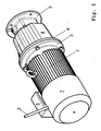
- FIG. 1 the geared motor with adapter is shown in a 3D perspective view.
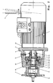
- FIG. 2 is a section through the adapter shown.
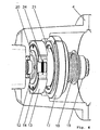
- FIG. 3 this section is enlarged and shown in FIG. 4 is a spatial view in a partially cut adapter to see.
- the motor is designed as a brake motor comprising a motor housing 1, in particular a cooling fins comprehensive, and a hood 7 for the B-side engine brake arranged, wherein the brake is designed as an electromagnetically actuated brake.
- the hood 7 is also useful in engines that include not only a B-side brake but additionally B-side encoders and / or fans.
- the brake In de-energized operation, the brake is applied because compression springs press an armature disc of the brake against a brake pad carrier with brake pad.
- a brake lever 2 the brake is released; This is carried out such that the armature disk and the Bremsbeiagexcellent with brake pad can be brought apart by means of the actuation of a brake lever and then the rotor of the electric motor is freely rotatable.
- a Bowden cable 23 is connected to this brake lever 2, which is arranged to actuate a locking of an A-side, integrated in an adapter designed and cooperating with an adapter clutch centrifugal brake.
- the electric motor 1 has electrical connection devices for the electrical supply lines and the brake lines in its terminal box.
- the motor 1 is connected by means of its motor flange 3 with the adapter housing part 4, which in turn is connected to the transmission housing cover 5 and for this purpose has a corresponding, precisely worked interface for releasable connection.
- the gear housing cover 5 sits a bearing 11 and a driven side bearing arranged, the advantageously as a roller bearing 10 is executable.
- the adapter shaft 9 is mounted in the housing part 5.
- the adapter shaft 9 is connected by means of a dog clutch with the motor shaft 8, so the rotor shaft.
- the dog clutch consists of a first and a second coupling part, each comprising jaws which engage with each other.
- the first coupling part 19 is positively connected by means of key 22 with the motor shaft 8.
- the second coupling part is designed as a Fliehbackenexcellent 12 with claws.
- the centrifugal jaws 14 are arranged on the circumference of the second coupling part and held by the holding plates (15,20) in its axial position. In the radial direction, the centrifugal jaws 14 are arranged to be movable, although the centrifugal jaws 14 have a lathed extension and there by means of circumferentially arranged springs, namely by means of in FIG. 4 shown tension springs 24 for centrifugal jaws, are held together and can overcome the spring force and change their radial position only when a correspondingly large centrifugal force occurs. But prevents the Arretierglocke 21 this radial movement when the lock is active, ie the in FIG. 3 shown state.
- the locking bell 21 has a cylindrical end portion which blocks an axial end portion on the outer circumference of the centrifugal jaws.
- the Bowden cable 23 of the associated switching body 17 moves axially away from the centrifugal bodies, overcoming the spring force of the spring 18, and the bearing 16, via which the non-co-rotating switching body 17 is mounted on the locking bell 21, moves away and thus dearretiert, so the centrifugal jaws 14 released.
- the spring 18 presses the locking bell 21 again in the locked state, ie in the state of locking the centrifugal jaws by means of the locking bell when the Bowden cable no longer exerts force.
- the adapter housing thus has not only the housing function but also the function of a friction surface and ensures the removal of the frictional heat generated during braking to the environment.
- a material which has good thermal conductivity It is essential that the engine can reach high operating temperatures and thus a dissipation of heat over the range of the engine and the motor housing unfavorable would.
- the Adaptergeophuseausfilhrung is therefore advantageous if the thermal resistance of the friction surface to the environment is lower than the thermal resistance of the friction surface above the inner region of the engine including the rotor and the motor housing to the environment.
- the brake lever 2 is mechanically coupled to the Bowden cable 23.
- the Bowden cable is connected directly to the brake cable with its end and is thus actuated immediately upon rotation of the brake lever 2 of the Bowden cable 23.
- the engine brake is released only after turning for a certain minimum amount.
- FIG. 2 In FIG. 2 is shown a starting position of the brake lever 2 and another, dashed line position.
- the named critical value of rotational speed or centrifugal force is determined by the structural design and dimensioning, thus also dimensioning, of all components.
- a significant advantage of the invention is thus that by means of this design, the critical value is so providable that it is smaller than the operating speed, by means of the locking means is releasable, whether the braking effect occurs or not.
- the centrifugal jaws achieve braking effect even at a very low rotational speed and corresponding shift lever position. This allows for very different types of applications.
- an embodiment is providable, in the beginning, so in the free travel, only the brake is released and then only the lock is releasable.
- dearrating and airing are predictable at the same time.
- Embodiments are also conceivable in which, instead of being locked, the locking is achieved.
- a Bowden cable and technically equivalent couplings between brake lever and locking bell of the centrifugal clutch are advantageously executable. It is essential that the mechanical part for this purpose has an equivalent mode of action.
- another coupling according to the prior art can be used advantageously, such as tooth clutch or other positive, frictional and / or non-positive clutches.
- an adapter of the type described that is, with an executable by locking switching function or not.
- the adapter housing is provided with a closure means.
- FIG. 5 a further embodiment is shown in which the first and second coupling part, ie jaw coupling part and Fliehback carrier are made in one piece as Fliehbackendelt 508.
- the coupling part function is integrated in this Fliehbackenriad.
- the transmission case cover 501 is detachably connected to the adapter case 504.
- the adapter shaft 502 is supported by bearings 505 and 506.
- the motor flange 503 is detachably connected to the adapter housing part 504.
- the centrifugal jaws 509 with brake lining 510 are provided on the centrifugal jaw carrier 508.
- the locking bell 511 is in turn pressed by the spring element 512 for locking in the centrifugal jaws 509, depending on the position of the shift lever 516, which is fixedly connected at its one end to a ball 515 or has a correspondingly shaped spherical end. With this ball, the shift lever 516 engages in a bearing 513 mounted on the switch body ring and can therefore perform an axial movement of the switch body.
- a lever extension 519 is screwed in, which is advantageous for manual operation.
- the shift lever is coupled to the brake lever 518 of the motor with joint.
- the adapter housing part 604 comprises a coil 620 in a bobbin 621. With this coil, a magnetic field is generated, which makes the locking bell 611 due to the reluctance effect in the axial direction against the spring force of the springs 612 movable on the turn integrally designed Fliehbackenarni 608th
- the mechanical coupling between the brake and centrifugal clutch is also replaceable by an electronically executed coupling.
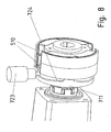
- FIG. 7 another embodiment is shown, in which the shape of the locking bell 711 is selected such that by retracting the locking unit 723, an axial movement of the locking bell 711 can be generated against the springs 712.
- the locking bell 711 is by means of a driving ball 722 in Fliehbackenarme 708 for torque transmission held.
- torque is transmittable up to a critical value from exceeding the critical torque value advances the driver ball 722.
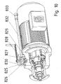
- FIG. 9 and 10 a further embodiment is shown in partial section, in which in turn the transmission housing cover 801, the adapter shaft 802 is mounted via bearings 805 and bearing 806. To the motor flange 803, the adapter housing part 804 is connected.
- the motor shaft 807 is in turn connected to the Fliehbackenarme 808, which is connected to the centrifugal jaws 809 and 810, for which the adapter housing part 804 is provided as a braking surface.
- the locking bell 811 must be moved axially against the spring force of the spring element 812.
- the switching body 814 mounted on the locking bell 811 via bearing 813 is axially movable when the switching shaft 829 is rotated, for example by 90 °.
- the shift shaft 829 is namely formed accordingly at its end facing the switch body.
- the rotary movement is triggered by manual operation, ie by turning the hand lever 827 with handle.
- leg spring 826 When the manual operation is completed, a reverse rotation is effected by the leg spring 826 whose first end is connected in the adapter housing part 804 and whose second end is connected to the pin 831 with the switching shaft 829.
- the camshaft 829 also carries a cam 825 disposed within the housing forming lid 830, which is shaped so that when a greater rotation than the above, for example, 180 °, is performed, the cam moves the pad 828 in the B side direction. This movement is then transmitted by means of the push rod 832 and the hinge 833 to the brake lever of the brake for releasing the same.
- the orientation and shape of the end of the switching shaft 829 determines the value of the rotation angle from which the centrifugal brake is released. The braking is then speed-dependent.
- the orientation and shape of the cam 825 determines the value of the angle of rotation from which the brake is vented.
- a rotation of the hand lever 827 by means of an electric motor, stepper motor or actuator is possible.
- the brake itself and also the electric motor is advantageous according to the characteristics of DE 199 24 735 A1 and / or according to the state of the art cited therein, in particular FIG. 1 corresponding.
Claims (14)
- Adaptateur conçu pour relier un premier dispositif et un second dispositif,
sachant qu'un arbre (8) du premier dispositif peut être relié, par concordance de formes et/ou mécaniquement, à une première partie d'accouplement (19) dudit adaptateur,
sachant que ladite première partie d'accouplement (19) est prévue pour coopérer avec une seconde partie d'accouplement (12), en vue de la transmission d'un couple de rotation,
sachant qu'un arbre d'adaptateur (9) peut être relié, par concordance de formes et/ou mécaniquement, à ladite seconde partie d'accouplement (12) de l'adaptateur,
sachant que le carter (4) de l'adaptateur offre un interface, vers le premier dispositif, en vue de la liaison libérable, avec faculté de centrage réciproque, avec le carter dudit premier dispositif,
sachant que ledit carter (4) de l'adaptateur offre, côté mené, un autre interface (5) en vue de la liaison libérable, avec faculté de centrage réciproque, avec une partie du carter du second dispositif, en particulier avec un couvercle de carter de transmission,
caractérisé par
la présence, sur le pourtour de la seconde partie d'accouplement (12), de mâchoires centrifuges (14) dont la cohésion est assurée par des ressorts (24) et au moyen desquelles, lors d'un dépassement d'une valeur critique de la vitesse angulaire et/ou de la force centrifuge, une garniture de freinage (13) peut être pressée sur une surface de frottement du carter (4) de l'adaptateur,
sachant que lesdites mâchoires centrifuges (14) peuvent être arrêtées de façon telle que ladite garniture de freinage exerce une pression, sur ladite surface de frottement, uniquement lorsqu'un moyen d'arrêt est neutralisé et qu'une valeur critique de la vitesse angulaire est dépassée,
sachant qu'une calotte d'arrêt (21), remplissant la fonction d'un moyen d'arrêt, peut être animée de coulissements à l'aide d'un levier et/ou d'une biellette,
sachant que ledit levier est relié à un levier de freinage (2) de façon telle que, lors d'un actionnement et notamment d'une rotation dudit levier de freinage, ladite calotte d'arrêt (21) puisse être animée de coulissements en vue de la neutralisation de l'arrêt, c'est-à-dire en vue du déverrouillage ; et qu'un désaérage du frein, en particulier du frein moteur, puisse avoir lieu lors d'une poursuite de l'actionnement, en particulier de la rotation. - Adaptateur selon la revendication 1,
caractérisé par le fait que
le premier dispositif est un moteur électrique entraîneur (1, 7), et le second dispositif est une transmission située côté mené. - Adaptateur selon au moins l'une des revendications précédentes,
caractérisé par le fait que
les première et seconde parties d'accouplement sont de réalisation monobloc, c'est-à-dire d'une seule pièce. - Adaptateur selon au moins l'une des revendications précédentes,
caractérisé par le fait que
l'arbre d'adaptateur est monté par au moins un palier (10, 11), notamment par deux paliers (10, 11), dans la partie de carter de transmission telle qu'un couvercle (5) du carter de transmission ou ledit carter de transmission ; et peut être relié, côté mené, à une partie dentée de ladite transmission. - Adaptateur selon au moins l'une des revendications précédentes,
caractérisé par le fait
qu'une calotte d'arrêt (21), prévue en tant que moyen d'arrêt, est agencée à coulissement axial, en particulier sur une douille disposée sur le pourtour des première et seconde parties d'accouplement (19, 12). - Adaptateur selon au moins l'une des revendications précédentes,
caractérisé par le fait que
la calotte d'arrêt (21) peut être animée de coulissements dans une direction axiale, par un ou plusieurs ressort(s) (18) ; et peut être amenée à la position de libération par coulissement dans l'autre direction axiale, au moyen d'un autre élément constitutif ou d'un autre dispositif (16, 17, 23). - Adaptateur selon au moins l'une des revendications précédentes,
caractérisé par le fait que
la calotte d'arrêt (21) est montée, par l'intermédiaire d'un palier (16), dans une pièce non rotative par rapport au carter (4) de l'adaptateur, en particulier dans un organe de commutation (17), cette pièce non rotative étant agencée à coulissement axial conjointement audit palier (16) et à ladite calotte d'arrêt (21). - Adaptateur selon au moins l'une des revendications précédentes,
caractérisé par le fait que
la pièce non rotative peut être animée de coulissements au moyen d'une tringlerie Bowden (23). - Adaptateur selon au moins l'une des revendications précédentes,
caractérisé par le fait que
la tringlerie Bowden (23) est reliée à un levier de freinage (2) de façon telle que, lors d'un actionnement et notamment d'une rotation dudit levier de freinage, ladite calotte d'arrêt (21) puisse être animée de coulissements en vue de la neutralisation de l'arrêt, c'est-à-dire en vue du déverrouillage ; et qu'un désaérage du frein, en particulier du frein moteur, puisse avoir lieu lors d'une poursuite de l'actionnement, en particulier de la rotation. - Adaptateur selon au moins l'une des revendications précédentes,
caractérisé par le fait que
des premières griffes sont prévues sur la première partie d'accouplement (19) et
des secondes griffes, en prise avec lesdites premières griffes, sont prévues sur la seconde partie d'accouplement (12). - Electroréducteur
comprenant au moins un moteur électrique (1, 2, 6, 7), un adaptateur selon au moins l'une des revendications précédentes, et une transmission,
ledit adaptateur incluant un frein centrifuge, sachant qu'une surface de frottement, prévue dans la surface intérieure du carter de l'adaptateur, est associée à la garniture de freinage,
caractérisé par le fait que
le moteur électrique (1, 2, 6, 7) englobe un frein actionnable électromagnétiquement, en particulier un frein moteur qui renferme un dispositif de désaérage du frein, tel qu'un levier de freinage (2) ou élément similaire,
sachant qu'un arrêt dudit frein centrifuge peut également être commandé au moyen dudit dispositif de désaérage du frein. - Electroréducteur selon la revendication 11,
caractérisé par le fait que
le frein actionnable électromagnétiquement est un frein moteur. - Electroréducteur selon la revendication 11,
caractérisé par le fait que
le dispositif de désaérage du frein est un levier de freinage. - Ensemble modulaire d'électroréducteurs,
incluant au moins une taille de réalisation englobant, à chaque fois, au moins deux variantes d'électroréducteurs équipés d'adaptateurs,
la première variante comprenant un adaptateur selon l'une des revendications 1 à 10, de manière à autoriser un arrêt ou une neutralisation de l'arrêt,
et la seconde variante comprenant un adaptateur selon l'une des revendications 1 à 10, sachant toutefois que des évidements, pratiqués dans le carter dudit adaptateur et affectés à des moyens d'arrêt, sont obturés par des moyens obturateurs, et que les éléments constitutifs sont déverrouillés.
Applications Claiming Priority (7)
| Application Number | Priority Date | Filing Date | Title |
|---|---|---|---|
| DE10260078 | 2002-12-19 | ||
| DE10260078 | 2002-12-19 | ||
| DE10305434A DE10305434B4 (de) | 2002-12-19 | 2003-02-11 | Adapter und Getriebemotor |
| DE10305434 | 2003-02-11 | ||
| DE10353909 | 2003-11-18 | ||
| DE10353909 | 2003-11-18 | ||
| PCT/EP2003/014038 WO2004057732A1 (fr) | 2002-12-19 | 2003-12-11 | Adaptateur, electroreducteur et boitier d'electroreducteur |
Publications (2)
| Publication Number | Publication Date |
|---|---|
| EP1576713A1 EP1576713A1 (fr) | 2005-09-21 |
| EP1576713B1 true EP1576713B1 (fr) | 2009-09-02 |
Family
ID=32685655
Family Applications (1)
| Application Number | Title | Priority Date | Filing Date |
|---|---|---|---|
| EP03795882A Expired - Lifetime EP1576713B1 (fr) | 2002-12-19 | 2003-12-11 | Adaptateur, electroreducteur et boitier d'electroreducteur |
Country Status (3)
| Country | Link |
|---|---|
| EP (1) | EP1576713B1 (fr) |
| AU (1) | AU2003298173A1 (fr) |
| WO (1) | WO2004057732A1 (fr) |
Cited By (4)
| Publication number | Priority date | Publication date | Assignee | Title |
|---|---|---|---|---|
| DE102009022706A1 (de) * | 2009-05-26 | 2010-12-02 | Siemens Aktiengesellschaft | Fahrgeschäft |
| DE102017107519A1 (de) * | 2017-04-07 | 2018-10-11 | Auma Riester Gmbh & Co. Kg | Stellantrieb mit Bremsvorrichtung |
| ES2706394A1 (es) * | 2018-06-08 | 2019-03-28 | Embragatges I Derivats S A | Freno centrifugo desacoplable para un equipo elevador |
| WO2023099024A1 (fr) * | 2021-11-30 | 2023-06-08 | Sew-Eurodrive Gmbh & Co. Kg | Entraînement comprenant une transmission avec un carter de transmission, ensemble frein à actionnement électromagnétique et moteur électrique |
Families Citing this family (6)
| Publication number | Priority date | Publication date | Assignee | Title |
|---|---|---|---|---|
| DE102007014707B4 (de) * | 2007-03-23 | 2009-12-17 | Sew-Eurodrive Gmbh & Co. Kg | Getriebe, Baukasten und Verfahren |
| DE102010049748B4 (de) * | 2010-10-29 | 2022-09-08 | Sew-Eurodrive Gmbh & Co Kg | Elektromotor |
| EP2735774A1 (fr) * | 2012-11-26 | 2014-05-28 | Siemens Aktiengesellschaft | Adaptateur de couplage |
| EP3023673B1 (fr) * | 2014-11-24 | 2018-01-31 | Siemens Aktiengesellschaft | Chaîne cinématique et dispositif adaptateur |
| DE102015201501A1 (de) * | 2015-01-29 | 2016-08-04 | Aktiebolaget Skf | Getriebeanordnung |
| FR3093959B1 (fr) * | 2019-03-22 | 2022-09-09 | Renault Sas | Motorisation electrique et procede d’usinage de carter |
Family Cites Families (6)
| Publication number | Priority date | Publication date | Assignee | Title |
|---|---|---|---|---|
| DE2919644C2 (de) | 1979-05-16 | 1983-09-08 | Robert Scheuffele GmbH & Co KG, 7120 Bietigheim-Bissingen | Fliehkraft-Schaltkupplung |
| SE8007159L (sv) * | 1980-10-13 | 1982-04-14 | Asea Ab | Hallbroms |
| DE3840281C2 (de) * | 1988-11-30 | 1997-12-04 | Zahnradfabrik Friedrichshafen | Hebezeugantrieb |
| EP0761925A1 (fr) * | 1995-09-07 | 1997-03-12 | Becker Antriebe GmbH | Dispositif de frein pour un rideau coupe-fumée, rideau coupe-feu ou rideau similaire |
| DE19637361C2 (de) * | 1996-09-13 | 1998-10-08 | Sew Eurodrive Gmbh & Co | Adapter und Adaptersystem zum Verbinden von Motoren mit Getrieben |
| DE19935196C1 (de) * | 1999-07-27 | 2000-12-28 | Abb Patent Gmbh | Bremsbarer elektromotorischer Antrieb |
-
2003
- 2003-12-11 EP EP03795882A patent/EP1576713B1/fr not_active Expired - Lifetime
- 2003-12-11 AU AU2003298173A patent/AU2003298173A1/en not_active Abandoned
- 2003-12-11 WO PCT/EP2003/014038 patent/WO2004057732A1/fr not_active Application Discontinuation
Cited By (5)
| Publication number | Priority date | Publication date | Assignee | Title |
|---|---|---|---|---|
| DE102009022706A1 (de) * | 2009-05-26 | 2010-12-02 | Siemens Aktiengesellschaft | Fahrgeschäft |
| DE102017107519A1 (de) * | 2017-04-07 | 2018-10-11 | Auma Riester Gmbh & Co. Kg | Stellantrieb mit Bremsvorrichtung |
| ES2706394A1 (es) * | 2018-06-08 | 2019-03-28 | Embragatges I Derivats S A | Freno centrifugo desacoplable para un equipo elevador |
| WO2019234267A1 (fr) * | 2018-06-08 | 2019-12-12 | Embragatges I Derivats, S.A. | Frein centrifuge désaccouplable pour équipement élévateur |
| WO2023099024A1 (fr) * | 2021-11-30 | 2023-06-08 | Sew-Eurodrive Gmbh & Co. Kg | Entraînement comprenant une transmission avec un carter de transmission, ensemble frein à actionnement électromagnétique et moteur électrique |
Also Published As
| Publication number | Publication date |
|---|---|
| EP1576713A1 (fr) | 2005-09-21 |
| WO2004057732A1 (fr) | 2004-07-08 |
| AU2003298173A1 (en) | 2004-07-14 |
Similar Documents
| Publication | Publication Date | Title |
|---|---|---|
| EP3354920B1 (fr) | Système d'embrayage pour un groupe propulseur et transmission comprenant un tel système d'embrayage | |
| EP1388682B1 (fr) | Dispositif de transmission de couple dans un automobile | |
| WO2018054412A1 (fr) | Système d'actionnement et dispositif embrayage pour un véhicule automobile | |
| EP2041446B1 (fr) | Roue libre à complémentarité de forme à commande électromécanique, frein électromécanique de véhicule automobile pourvu d'une roue libre de ce type et procédé de réglage du jeu d'un frein de ce type | |
| EP1576713B1 (fr) | Adaptateur, electroreducteur et boitier d'electroreducteur | |
| DE102009028568B4 (de) | Vorrichtung zur Blockierung eines linearen Stellantriebs | |
| DE102005022218A1 (de) | Drehmomentübertragunsmechanismus mit Sperrvorrichtung | |
| DE3918565A1 (de) | Differentialgetriebe | |
| WO2016165701A1 (fr) | Système d'embrayage | |
| EP1143160A2 (fr) | Ensemble à embrayage double | |
| DE10305434B4 (de) | Adapter und Getriebemotor | |
| DE102015209791B3 (de) | Kupplungssystem | |
| DE102014214297B4 (de) | Kupplungsanordnung | |
| EP2284413B1 (fr) | Couplage de limitation du couple | |
| EP2438275B1 (fr) | Embrayage ou frein dans ou sur une transmission | |
| DE60204256T2 (de) | Durch Drehmoment lösbare Scheibenbremse | |
| EP1400716B1 (fr) | Système d'embrayage et dispositif de retenue pour retenir au moins un embrayage du système d'embrayage dans un état temporaire ou dans un état d'engagement prédéterminé | |
| DE10234848A1 (de) | Elektromechanische Bremse | |
| DE2128418A1 (de) | Waschmaschinenantrieb | |
| DE4225158A1 (de) | Elektromaschinensystem | |
| EP0729913B1 (fr) | Palan à chaíne muni d'un accoupplement actionné par un frein | |
| DE10018646A1 (de) | Doppelkupplungsanordnung | |
| DE102017202248B4 (de) | Kupplungsanordnung für einen Antriebsstrang eines Kraftfahrzeugs | |
| DE19848584A1 (de) | Selbstverstärkende Reibungskupplung | |
| EP1293696A1 (fr) | Embrayage limitateur de couple |
Legal Events
| Date | Code | Title | Description |
|---|---|---|---|
| PUAI | Public reference made under article 153(3) epc to a published international application that has entered the european phase |
Free format text: ORIGINAL CODE: 0009012 |
|
| 17P | Request for examination filed |
Effective date: 20050719 |
|
| AK | Designated contracting states |
Kind code of ref document: A1 Designated state(s): AT BE BG CH CY CZ DE DK EE ES FI FR GB GR HU IE IT LI LU MC NL PT RO SE SI SK TR |
|
| AX | Request for extension of the european patent |
Extension state: AL LT LV MK |
|
| DAX | Request for extension of the european patent (deleted) | ||
| TPAC | Observations filed by third parties |
Free format text: ORIGINAL CODE: EPIDOSNTIPA |
|
| 17Q | First examination report despatched |
Effective date: 20061221 |
|
| GRAP | Despatch of communication of intention to grant a patent |
Free format text: ORIGINAL CODE: EPIDOSNIGR1 |
|
| RAP1 | Party data changed (applicant data changed or rights of an application transferred) |
Owner name: HESS, ANDREAS Owner name: SEW-EURODRIVE GMBH & CO |
|
| GRAS | Grant fee paid |
Free format text: ORIGINAL CODE: EPIDOSNIGR3 |
|
| GRAA | (expected) grant |
Free format text: ORIGINAL CODE: 0009210 |
|
| RAP1 | Party data changed (applicant data changed or rights of an application transferred) |
Owner name: SEW-EURODRIVE GMBH & CO |
|
| AK | Designated contracting states |
Kind code of ref document: B1 Designated state(s): AT BE BG CH CY CZ DE DK EE ES FI FR GB GR HU IE IT LI LU MC NL PT RO SE SI SK TR |
|
| REG | Reference to a national code |
Ref country code: CH Ref legal event code: EP |
|
| REG | Reference to a national code |
Ref country code: IE Ref legal event code: FG4D Free format text: LANGUAGE OF EP DOCUMENT: GERMAN |
|
| REF | Corresponds to: |
Ref document number: 50311876 Country of ref document: DE Date of ref document: 20091015 Kind code of ref document: P |
|
| PG25 | Lapsed in a contracting state [announced via postgrant information from national office to epo] |
Ref country code: FI Free format text: LAPSE BECAUSE OF FAILURE TO SUBMIT A TRANSLATION OF THE DESCRIPTION OR TO PAY THE FEE WITHIN THE PRESCRIBED TIME-LIMIT Effective date: 20090902 Ref country code: SE Free format text: LAPSE BECAUSE OF FAILURE TO SUBMIT A TRANSLATION OF THE DESCRIPTION OR TO PAY THE FEE WITHIN THE PRESCRIBED TIME-LIMIT Effective date: 20090902 |
|
| NLV1 | Nl: lapsed or annulled due to failure to fulfill the requirements of art. 29p and 29m of the patents act | ||
| PG25 | Lapsed in a contracting state [announced via postgrant information from national office to epo] |
Ref country code: NL Free format text: LAPSE BECAUSE OF FAILURE TO SUBMIT A TRANSLATION OF THE DESCRIPTION OR TO PAY THE FEE WITHIN THE PRESCRIBED TIME-LIMIT Effective date: 20090902 Ref country code: SI Free format text: LAPSE BECAUSE OF FAILURE TO SUBMIT A TRANSLATION OF THE DESCRIPTION OR TO PAY THE FEE WITHIN THE PRESCRIBED TIME-LIMIT Effective date: 20090902 |
|
| PG25 | Lapsed in a contracting state [announced via postgrant information from national office to epo] |
Ref country code: CY Free format text: LAPSE BECAUSE OF FAILURE TO SUBMIT A TRANSLATION OF THE DESCRIPTION OR TO PAY THE FEE WITHIN THE PRESCRIBED TIME-LIMIT Effective date: 20090902 |
|
| REG | Reference to a national code |
Ref country code: IE Ref legal event code: FD4D |
|
| PG25 | Lapsed in a contracting state [announced via postgrant information from national office to epo] |
Ref country code: ES Free format text: LAPSE BECAUSE OF FAILURE TO SUBMIT A TRANSLATION OF THE DESCRIPTION OR TO PAY THE FEE WITHIN THE PRESCRIBED TIME-LIMIT Effective date: 20091213 Ref country code: RO Free format text: LAPSE BECAUSE OF FAILURE TO SUBMIT A TRANSLATION OF THE DESCRIPTION OR TO PAY THE FEE WITHIN THE PRESCRIBED TIME-LIMIT Effective date: 20090902 Ref country code: PT Free format text: LAPSE BECAUSE OF FAILURE TO SUBMIT A TRANSLATION OF THE DESCRIPTION OR TO PAY THE FEE WITHIN THE PRESCRIBED TIME-LIMIT Effective date: 20100104 Ref country code: IE Free format text: LAPSE BECAUSE OF FAILURE TO SUBMIT A TRANSLATION OF THE DESCRIPTION OR TO PAY THE FEE WITHIN THE PRESCRIBED TIME-LIMIT Effective date: 20090902 Ref country code: CZ Free format text: LAPSE BECAUSE OF FAILURE TO SUBMIT A TRANSLATION OF THE DESCRIPTION OR TO PAY THE FEE WITHIN THE PRESCRIBED TIME-LIMIT Effective date: 20090902 Ref country code: EE Free format text: LAPSE BECAUSE OF FAILURE TO SUBMIT A TRANSLATION OF THE DESCRIPTION OR TO PAY THE FEE WITHIN THE PRESCRIBED TIME-LIMIT Effective date: 20090902 |
|
| PG25 | Lapsed in a contracting state [announced via postgrant information from national office to epo] |
Ref country code: SK Free format text: LAPSE BECAUSE OF FAILURE TO SUBMIT A TRANSLATION OF THE DESCRIPTION OR TO PAY THE FEE WITHIN THE PRESCRIBED TIME-LIMIT Effective date: 20090902 |
|
| BERE | Be: lapsed |
Owner name: SEW-EURODRIVE G.M.B.H. & CO Effective date: 20091231 |
|
| PLBE | No opposition filed within time limit |
Free format text: ORIGINAL CODE: 0009261 |
|
| STAA | Information on the status of an ep patent application or granted ep patent |
Free format text: STATUS: NO OPPOSITION FILED WITHIN TIME LIMIT |
|
| PG25 | Lapsed in a contracting state [announced via postgrant information from national office to epo] |
Ref country code: MC Free format text: LAPSE BECAUSE OF NON-PAYMENT OF DUE FEES Effective date: 20100701 Ref country code: DK Free format text: LAPSE BECAUSE OF FAILURE TO SUBMIT A TRANSLATION OF THE DESCRIPTION OR TO PAY THE FEE WITHIN THE PRESCRIBED TIME-LIMIT Effective date: 20090902 |
|
| REG | Reference to a national code |
Ref country code: CH Ref legal event code: PL |
|
| 26N | No opposition filed |
Effective date: 20100603 |
|
| PG25 | Lapsed in a contracting state [announced via postgrant information from national office to epo] |
Ref country code: BE Free format text: LAPSE BECAUSE OF NON-PAYMENT OF DUE FEES Effective date: 20091231 Ref country code: CH Free format text: LAPSE BECAUSE OF NON-PAYMENT OF DUE FEES Effective date: 20091231 Ref country code: GR Free format text: LAPSE BECAUSE OF FAILURE TO SUBMIT A TRANSLATION OF THE DESCRIPTION OR TO PAY THE FEE WITHIN THE PRESCRIBED TIME-LIMIT Effective date: 20091203 Ref country code: LI Free format text: LAPSE BECAUSE OF NON-PAYMENT OF DUE FEES Effective date: 20091231 |
|
| PG25 | Lapsed in a contracting state [announced via postgrant information from national office to epo] |
Ref country code: BG Free format text: LAPSE BECAUSE OF FAILURE TO SUBMIT A TRANSLATION OF THE DESCRIPTION OR TO PAY THE FEE WITHIN THE PRESCRIBED TIME-LIMIT Effective date: 20091231 Ref country code: IT Free format text: LAPSE BECAUSE OF NON-PAYMENT OF DUE FEES Effective date: 20091211 |
|
| PG25 | Lapsed in a contracting state [announced via postgrant information from national office to epo] |
Ref country code: LU Free format text: LAPSE BECAUSE OF NON-PAYMENT OF DUE FEES Effective date: 20091211 |
|
| PG25 | Lapsed in a contracting state [announced via postgrant information from national office to epo] |
Ref country code: AT Free format text: LAPSE BECAUSE OF NON-PAYMENT OF DUE FEES Effective date: 20091211 |
|
| PG25 | Lapsed in a contracting state [announced via postgrant information from national office to epo] |
Ref country code: HU Free format text: LAPSE BECAUSE OF FAILURE TO SUBMIT A TRANSLATION OF THE DESCRIPTION OR TO PAY THE FEE WITHIN THE PRESCRIBED TIME-LIMIT Effective date: 20100303 |
|
| PGRI | Patent reinstated in contracting state [announced from national office to epo] |
Ref country code: IT Effective date: 20110616 |
|
| PG25 | Lapsed in a contracting state [announced via postgrant information from national office to epo] |
Ref country code: TR Free format text: LAPSE BECAUSE OF FAILURE TO SUBMIT A TRANSLATION OF THE DESCRIPTION OR TO PAY THE FEE WITHIN THE PRESCRIBED TIME-LIMIT Effective date: 20090902 |
|
| REG | Reference to a national code |
Ref country code: FR Ref legal event code: PLFP Year of fee payment: 13 |
|
| REG | Reference to a national code |
Ref country code: FR Ref legal event code: PLFP Year of fee payment: 14 |
|
| REG | Reference to a national code |
Ref country code: FR Ref legal event code: PLFP Year of fee payment: 15 |
|
| PGFP | Annual fee paid to national office [announced via postgrant information from national office to epo] |
Ref country code: IT Payment date: 20221111 Year of fee payment: 20 Ref country code: GB Payment date: 20221103 Year of fee payment: 20 Ref country code: FR Payment date: 20221110 Year of fee payment: 20 Ref country code: DE Payment date: 20221231 Year of fee payment: 20 |
|
| REG | Reference to a national code |
Ref country code: DE Ref legal event code: R071 Ref document number: 50311876 Country of ref document: DE |
|
| REG | Reference to a national code |
Ref country code: GB Ref legal event code: PE20 Expiry date: 20231210 |
|
| PG25 | Lapsed in a contracting state [announced via postgrant information from national office to epo] |
Ref country code: GB Free format text: LAPSE BECAUSE OF EXPIRATION OF PROTECTION Effective date: 20231210 |
|
| PG25 | Lapsed in a contracting state [announced via postgrant information from national office to epo] |
Ref country code: GB Free format text: LAPSE BECAUSE OF EXPIRATION OF PROTECTION Effective date: 20231210 |