EP1576343B2 - Weighing module comprising a dust-removal device - Google Patents
Weighing module comprising a dust-removal device Download PDFInfo
- Publication number
- EP1576343B2 EP1576343B2 EP03796003.6A EP03796003A EP1576343B2 EP 1576343 B2 EP1576343 B2 EP 1576343B2 EP 03796003 A EP03796003 A EP 03796003A EP 1576343 B2 EP1576343 B2 EP 1576343B2
- Authority
- EP
- European Patent Office
- Prior art keywords
- gas
- housing
- weighing module
- dust
- distributor
- Prior art date
- Legal status (The legal status is an assumption and is not a legal conclusion. Google has not performed a legal analysis and makes no representation as to the accuracy of the status listed.)
- Expired - Lifetime
Links
- 238000005303 weighing Methods 0.000 title claims abstract description 40
- 239000000428 dust Substances 0.000 claims abstract description 37
- 238000000034 method Methods 0.000 claims abstract description 6
- 230000005540 biological transmission Effects 0.000 claims description 22
- 230000007717 exclusion Effects 0.000 abstract 1
- 238000005259 measurement Methods 0.000 abstract 1
- 239000007789 gas Substances 0.000 description 49
- 238000000151 deposition Methods 0.000 description 3
- 238000009826 distribution Methods 0.000 description 3
- 238000004140 cleaning Methods 0.000 description 2
- 230000008021 deposition Effects 0.000 description 2
- 238000007789 sealing Methods 0.000 description 2
- 230000015572 biosynthetic process Effects 0.000 description 1
- 238000011109 contamination Methods 0.000 description 1
- 230000001419 dependent effect Effects 0.000 description 1
- 230000003670 easy-to-clean Effects 0.000 description 1
- 230000000694 effects Effects 0.000 description 1
- 238000009434 installation Methods 0.000 description 1
- 230000035515 penetration Effects 0.000 description 1
- 239000002244 precipitate Substances 0.000 description 1
- 230000001681 protective effect Effects 0.000 description 1
- 230000001105 regulatory effect Effects 0.000 description 1
Images

Classifications
-
- G—PHYSICS
- G01—MEASURING; TESTING
- G01G—WEIGHING
- G01G21/00—Details of weighing apparatus
- G01G21/30—Means for preventing contamination by dust
Definitions
- the invention relates to a balance, in particular a weighing module, with a load cell on all sides surrounding housing, with a force transmission member which is connectable to a load bearing device, wherein the transmission member passes through an opening of a housing wall and with a vertically movable part of the load cell in a rigid connection stands.
- Such scales or weighing modules are preferably used in industrial environments, for example as so-called belt weighers, wherein the weighing module is arranged, for example, below a conveyor belt in order to weigh objects transported by the latter.
- the environment in which such a weighing module is installed very dusty.
- the weighing module must be surrounded by a protective housing and, in particular in the region of openings of the housing, be protected by suitable measures against the ingress of dust.
- Particularly critical is the implementation of the power transmission member serving housing opening, as these must be known to be mandatory in order to connect a load bearing with the vertically movable part of the load cell can.
- various measures are proposed to prevent the ingress of dirt into the interior of a balance housing.
- the EP-A-1 146 322 a scale with a sealing lock, which consists in an elastic arbitrarily expandable and reducible device for installation between a fixed part connected to the balance housing and a movable part by the load relative to the balance housing.
- This device releases the moving part of the scale during the weighing process and keeps it locked during the rest of the time.
- the lock has a certain sealing effect, which is particularly efficient when the elastic means between the power transmission member and the balance housing is arranged.
- Another measure, as disclosed in the same document is to provide the power transmission member with a cup-shaped cover and optionally provide them as part of a labyrinth seal.
- the DE 85 08 424 U1 discloses an upper shell scale in which the interior of the housing can be externally vented.
- the housing has a connecting piece, through which a gas stream can be introduced into the interior of the housing.
- the weighing pan is supported via a connecting piece through an opening in the upper part of the housing onto a load receiver disposed within the housing.
- the housing On the bottom, the housing also has a breakthrough, with the load receptor extends into this breakthrough.
- these provisions may be sufficient to protect against the ingress of dust, but there is the problem that is relatively small by the cup-shaped cover, the distance between the fixed housing of the weighing module and the vertically movable power transmission member together with cover and so there is the danger that forms a dust bridge, so to speak, as a mechanical connection, between the two parts.
- This may be dust from the air or weighing goods falling from the load support.
- a dust bridge can already produce a mechanical short circuit and thereby falsify the weighing result.
- a balance in particular a weighing module with a housing surrounding a load cell on all sides, has a vertically movable force transmission member which is connectable to a load bearing device, wherein the force transmission member passes through a passage opening of a housing wall and is in a rigid connection with a vertically movable part of the load cell ,
- a gas supply device for dust removal which has a at least one flow channel having gas distributor to prevent dust deposition between the fixed housing and the vertically movable power transmission member.
- the at least one flow channel communicates with a gas inlet and has a gas outlet for generating a gas flow directed away from the movable part of the balance.
- the gas distributor may be arranged substantially within the balance housing or be placed on the balance housing from the outside.
- a method for preventing dust deposition between the stationary housing and the vertically movable power transmission member in a weighing, in particular a weighing module can be realized, in which a gas flow occurring both during the weighing operation and outside the weighing operation is directed away from the movable part of the balance ,
- the gas stream is continuous or alternatively in the form of pulsed gas ejections.
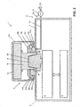
- the FIG. 1 schematically shows a weighing module 1, for example, to be arranged below a weighing section of a conveyor belt belt scale, which has a tightly closed, easy to clean housing 2.
- a known load cell 3 is arranged, which is connected to a weighing electronics 4.
- the power transmission member 6 is an integral part of the movable part of the balance.
- the pot-shaped cap 5 rests on a hub 13 connected to a part 14, which is placed on the cone-shaped force transducer 9.
- the hub part 14 has a corresponding cone-shaped receiving recess 36.
- the cap 5 has a sleeve-shaped outer ring 10 and a tubular inner ring 12 with different diameters, which are arranged coaxially to one another and laterally delimit an intermediate cavity.
- a labyrinth seal in cooperation with the concentric rings 10 and 12, a labyrinth seal against the ingress of dust into the balance housing 2 forming intermediate ring 11 between the outer ring 10 and the inner ring 12 on the housing 2 is arranged.
- the cap 5 can be lifted for the purpose of cleaning. This is especially necessary in dusty environment. However, since, as described above, even during the weighing operation a lot of dust on the balance housing 2 can precipitate, so that this forms a mechanical bridge between the non-movable balance housing 2 and the vertically movable power transmission member 6, in particular the cap 5, is the balance 1 provided with a device for dust removal 15, which in the in FIG. 1 embodiment shown is arranged primarily within the balance housing 2.
- the device for removing dust 15 has a gas distributor 16, which is fixedly connected to the underside of the housing wall 7 of the balance housing 2, and a gas supply device 17, which passes through the housing 2 passing gas, in particular compressed air, the gas distributor 16 from below.
- the gas pressure or that of the compressed air can be regulated via the valve 18.
- the gas distributor 16 has along its inner circumference a recess which forms a flow channel 19. In this, the gas or compressed air passes through a gas inlet 20.
- the compressed air from the flow channel 19 passes directly into a gas outlet 23, as a kind of gap, which is arranged parallel to the housing wall 7, and which blows under the cover 5 through the compressed air located in the flow channel 19 in the horizontal direction to the outside.
- a gas outlet 23 as a kind of gap, which is arranged parallel to the housing wall 7, and which blows under the cover 5 through the compressed air located in the flow channel 19 in the horizontal direction to the outside.
- this embodiment is the Device for removing dust 15 perfectly integrated into the balance housing 2.
- the supply of gas or compressed air is manually or automatically controlled by means of a valve 18, via a pressure line 34.
- the valve 18 has a manually operated or automatic device 35, which allows gas via the pressure line 34 in the flow channel 19th to introduce under a predefined pressure.
- FIG. 2 shows a weighing module with another embodiment of a device according to the invention for dust removal 115. Parts that in their execution compared to FIG. 1 are not changed are marked with the same reference numeral.
- This device for dust removal 115 can be mounted from the top to the top 7 of the balance housing 2 and is therefore modular, since the gas distributor 116 can be attached afterwards and can also be removed again at any time.
- the gas distributor 116 is formed in two parts and consists of a distributor ring 124 and a cover 125.
- first flow channel 119 is provided with a part of a first flow channel 119 forming special bulge, which comes to lie exactly above the gas inlet 120 with mounted on the distributor ring 124 lid 125 and which is adapted to introduce the gas or the compressed air into the circular first flow channel 119.
- the first flow channel 119 is connected to a second flow channel 126, to which the gas outlet 123, in turn configured as a gap encompassing the entire circumference of the gas distributor 116, follows.
- FIG. 2 embodiment shown on a simplified form of a cap 105.
- Such a two-part gas distributor 116 in addition to its improved mounting options still has the advantage of being particularly easy to disassemble for cleaning purposes.
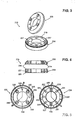
- a gas distributor 216 in three-dimensional representation, is depicted in a third embodiment. It consists in turn of a distributor ring 224 and a lid 225 and has as well as the basis of the FIG. 2 described embodiment, two preferably one above the other arranged flow channels (only one of which is visible in the figure).
- the first flow passage 219 is composed of a respective circular recess formed in the lower manifold ring and in the lid. This forms in the assembled state, the first flow channel, which with the second flow channel 226 via a plurality of preferably circular gas passage openings 227 (see also FIG. 5 ) is connected, through which flows the gas, or the compressed air, from the first into the second flow channel.
- the compressed air in turn passes through a gas outlet, in the form of an annular gap, which forms when mounted on the upper housing wall 7 gas distributor 216 between the housing wall 7 and lower distributor ring 224.
- the dimensions of the gap are at a thickness of 0.1 to 0.5 mm in order to maintain a sufficiently high flow pressure can.
- both the cover 225 and the distribution ring 224 of the gas distributor can be seen in the plan.
- the first flow channel 219 with the second flow channel 226 (see FIG. 4 ) connecting gas passage openings 227 are clearly visible here.
- For the attachment of the cover 225 on the distributor ring 224 serve screws which are screwed through the through holes 228 in the threaded holes 229 in the cover 225.
- the through-bores 230 in the cover 225 and the through-holes 231 in the distributor ring 224 are provided for fastening the gas distributor 216 to the upper housing wall 7.
- the opening 232 in the distributor ring 224 is part of the gas inlet and opens when the lid is mounted in a bulge 233, from where the compressed air enters the first flow channel 219.
- the second flow channel 226 (see Figur4 ) is connected to the at least one housing wall 7 such that a narrow gap is present through which the air flows in a predominantly radial direction to the outside.
- one-piece or multi-part, in particular two-part, embodiments of a gas distributor are conceivable, such having a flow channel or two flow channels communicating with one another.
- a device according to the invention for dust removal is not necessarily arranged on the upper housing wall. Rather, it is in each case arranged where the passage for the power transmission member is attached to the balance, so for example below, in the case of an underfloor scale, or on the side for a lateral passage of the power transmission member through the balance housing.
Landscapes
- Physics & Mathematics (AREA)
- General Physics & Mathematics (AREA)
- Measuring Volume Flow (AREA)
- Cleaning Implements For Floors, Carpets, Furniture, Walls, And The Like (AREA)
- Air Conditioning Control Device (AREA)
- Cleaning By Liquid Or Steam (AREA)
- Prevention Of Fouling (AREA)
- Filtering Of Dispersed Particles In Gases (AREA)
- Brushes (AREA)
- Structure Of Belt Conveyors (AREA)
- Framework For Endless Conveyors (AREA)
- Cleaning In General (AREA)
Abstract
Description
Die Erfindung betrifft eine Waage, insbesondere ein Wägemodul, mit einem eine Wägezelle allseitig umgebenden Gehäuse, mit einem Kraftübertragungsglied, welches mit einer Lastauflagevorrichtung verbindbar ist, wobei das Übertragungsglied durch eine Öffnung einer Gehäusewand hindurch tritt und mit einem vertikal beweglichen Teil der Wägezelle in starrer Verbindung steht.The invention relates to a balance, in particular a weighing module, with a load cell on all sides surrounding housing, with a force transmission member which is connectable to a load bearing device, wherein the transmission member passes through an opening of a housing wall and with a vertically movable part of the load cell in a rigid connection stands.
Solche Waagen oder Wägemodule finden ihren Einsatz bevorzugt in industrieller Umgebung, beispielsweise als sogenannte Bandwaagen, wobei das Wägemodul beispielsweise unterhalb eines Förderbandes angeordnet ist, um von letzterem transportierte Gegenstände zu verwiegen. Häufig ist jedoch die Umgebung, in welcher ein solches Wägemodul installiert ist, sehr staubig. Das heisst das Wägemodul muss von einem Schutzgehäuse umgeben sein und, insbesondere im Bereich von Öffnungen des Gehäuses, durch geeignete Massnahmen gegen das Eindringen von Staub geschützt werden. Als besonders kritisch erweist sich die der Durchführung des Kraftübertragungsgliedes dienende Gehäuseöffnung, da diese bekanntermassen zwingend vorhanden sein muss, um eine Lastauflage mit dem vertikal beweglichen Teil der Wägezelle verbinden zu können. Im Stand der Technik werden zur Vermeidung des Eindringens von Schmutz in das Innere eines Waagengehäuses verschiedene Massnahmen vorgeschlagen.Such scales or weighing modules are preferably used in industrial environments, for example as so-called belt weighers, wherein the weighing module is arranged, for example, below a conveyor belt in order to weigh objects transported by the latter. Frequently, however, the environment in which such a weighing module is installed, very dusty. This means that the weighing module must be surrounded by a protective housing and, in particular in the region of openings of the housing, be protected by suitable measures against the ingress of dust. Particularly critical is the implementation of the power transmission member serving housing opening, as these must be known to be mandatory in order to connect a load bearing with the vertically movable part of the load cell can. In the prior art, various measures are proposed to prevent the ingress of dirt into the interior of a balance housing.
So offenbart die
Die
In besonders staubiger Umgebung mögen diese Vorkehrungen zum Schutz gegen das Eindringen von Staub zwar ausreichend sein, es stellt sich jedoch das Problem, dass durch die topfförmige Abdeckung, der Abstand zwischen dem feststehenden Gehäuse des Wägemoduls und dem vertikal beweglichen Kraftübertragungsglied mitsamt Abdeckung relativ klein ist, und so die Gefahr besteht, dass sich eine Staubbrücke, sozusagen als mechanische Verbindung, zwischen den beiden Teilen ausbildet. Es kann sich dabei um Staub aus der Luft oder um von der Lastauflage herabfallendes Wägegut handeln. Bei Wägemodulen, die mit einer empfindlichen, hochauflösenden Wägezelle versehen sind, kann eine solche Staubbrücke bereits einen mechanischen Kurzschluss herstellen und dadurch das Wägeergebnis verfälschen.In dusty environments, these provisions may be sufficient to protect against the ingress of dust, but there is the problem that is relatively small by the cup-shaped cover, the distance between the fixed housing of the weighing module and the vertically movable power transmission member together with cover and so there is the danger that forms a dust bridge, so to speak, as a mechanical connection, between the two parts. This may be dust from the air or weighing goods falling from the load support. For weigh modules that are equipped with a sensitive, high-resolution load cell, such a dust bridge can already produce a mechanical short circuit and thereby falsify the weighing result.
Es ist daher Aufgabe der Erfindung, eine Waage, insbesondere ein Wägemodul, dahin gehend zu verbessern, dass die Ausbildung einer "Staubbrücke" zwischen feststehendem Gehäuse und beweglichem Teil der Waage vermieden wird.It is therefore an object of the invention to improve a balance, in particular a weighing module, to the extent that the formation of a "dust bridge" between the fixed housing and the movable part of the balance is avoided.
Diese Aufgabe wird erfindungsgemäss mit den Merkmalen des Anspruchs 1 gelöst. Eine Waage, insbesondere ein Wägemodul mit einem eine Wägezelle allseitig umgebenden Gehäuse, weist ein vertikal bewegliches Kraftübertragungsglied auf, welches mit einer Lastauflagevorrichtung verbindbar ist, wobei das Kraftübertragungsglied durch eine Durchtrittsöffnung einer Gehäusewand hindurch tritt und mit einem vertikal beweglichen Teil der Wägezelle in starrer Verbindung steht. Es ist eine mit einer Gaszufuhr versehene Vorrichtung zur Staubentfernung vorhanden, welche zur Vermeidung einer Staubablagerung zwischen dem feststehenden Gehäuse und dem vertikal beweglichen Kraftübertragungsglied über einen mindestens einen Strömungskanal aufweisenden Gasverteiler verfügt. Der mindestens eine Strömungskanal steht mit einem Gaseinlass in Verbindung und weist einen Gasauslass auf, zur Erzeugung eines vom beweglichen Teil der Waage weg gerichteten Gasstroms.This object is achieved according to the invention with the features of
Dies hat den Vorteil, dass sich keine Staubbrükken zwischen dem feststehenden und dem beweglichen Teil der Waage, insbesondere zwischen dem Kraftübertragungsglied und dem Waagengehäuse, bilden, und dass der Einfluss von Staub und sonstiger Verschmutzung auf das Wägeergebnis sowie auf dessen Anzeige minimiert ist.This has the advantage that no dust bridges between the fixed and the movable part of the balance, in particular between the power transmission member and the balance housing, form, and that the influence of dust and other contamination on the weighing result and on its display is minimized.
Weitere bevorzugte Gestaltungen sind Gegestand der Unteransprüche.Further preferred embodiments are the subject of the dependent claims.
Der Gasverteiler kann im wesentlichen innerhalb des Waagengehäuses angeordnet sein oder von aussen auf das Waagengehäuse aufgesetzt sein.The gas distributor may be arranged substantially within the balance housing or be placed on the balance housing from the outside.
Mit der Erfindung lässt sich ein Verfahren zur Vermeidung einer Staubablagerung zwischen dem feststehenden Gehäuse und dem vertikal beweglichen Kraftübertragungsglied bei einerWaage, insbesondere einem Wägemodul realisieren, bei welchem ein sowohl während des Wägevorgangs, als auch ausserhalb des Wägevorgangs erfolgender Gasstrom vom beweglichen Teil der Waage weggerichtet ist. In bevorzugter Weise erfolgt der Gasstrom kontinuierlich oder alternativ in Form von pulsförmigen Gasausstössen.With the invention, a method for preventing dust deposition between the stationary housing and the vertically movable power transmission member in a weighing, in particular a weighing module can be realized, in which a gas flow occurring both during the weighing operation and outside the weighing operation is directed away from the movable part of the balance , Preferably, the gas stream is continuous or alternatively in the form of pulsed gas ejections.
Nachfolgend wird die Erfindung anhand von stark schematisierten Zeichnungen näher erläutert. Dabei zeigt:
Figur 1- den Längsschnitt durch ein Wägemodul mit einer erfindungsgemässen Vorrichtung zum Entfernen des Staubs mittels eines Gases,
Figur 2- den Längsschnitt durch ein Wägemodul mit einer anderen erfindungsgemässen, oben auf dem Gehäuse anzubringenden Vorrichtung zum Entfernen des Staubs,
Figur 3- einen zweiteiligen Gasverteiler, in Perspektivischer Darstellung, in einer weiteren Ausführungsform,
Figur 4- den Gasverteiler aus
Figur 3 Figur 5- den Gasverteiler aus
Figur 3
- FIG. 1
- the longitudinal section through a weighing module with an inventive device for removing the dust by means of a gas,
- FIG. 2
- the longitudinal section through a weighing module with another inventive device to be mounted on top of the housing device for removing the dust,
- FIG. 3
- a two-part gas distributor, in perspective view, in a further embodiment,
- FIG. 4
- the gas distributor
FIG. 3 , on average, - FIG. 5
- the gas distributor
FIG. 3 in the supervision.
Die
Die topfförmige Abdeckkappe 5 ruht auf einem mit einem Nabenteil 14 verbundenen Aufsatz 13, welcher auf dem konusförmigen Kraftaufnehmer 9 aufgesetzt ist. Das Nabenteil 14 besitzt eine entsprechend konusförmige Aufnahmevertiefung 36.The pot-
Die Abdeckkappe 5 weist einen hülsenförmigen Aussenring 10 und einen röhrenförmigen Innenring 12 mit unterschiedlichen Durchmessern auf, die koaxial zueinander angeordnet sind und einen dazwischen liegenden Hohlraum seitlich begrenzen. Konzentrisch zur Öffnung 8 des Gehäuses 2 ist ein in Zusammenwirken mit den konzentrischen Ringen 10 und 12 eine Labyrinthdichtung gegen das Eindringen von Staub in das Waagengehäuse 2 bildender Zwischenring 11 zwischen dem Aussenring 10 und dem Innenring 12 am Gehäuse 2 angeordnet.The
Die Abdeckkappe 5 kann zum Zwecke der Reinigung abgehoben werden. Dies ist insbesondere in staubiger Umgebung erforderlich. Da sich jedoch, wie eingangs beschrieben, bereits während des Wägebetriebs sehr viel Staub auf dem Waagengehäuse 2 niederschlagen kann, so dass dieser eine mechanische Brücke zwischen dem nicht beweglichen Waagengehäuse 2 und dem vertikal beweglichen Kraftübertragungsglied 6, insbesondere der Abdeckkappe 5 ausbildet, ist die Waage 1 mit einer Vorrichtung zur Staubentfernung 15 versehen, die in der in
Die Vorrichtung zur Staubentfernung 15 verfügt über einen Gasverteiler 16, welcher fest mit der Unterseite der Gehäusewand 7 des Waagengehäuses 2 verbunden ist, sowie einer Gaszufuhreinrichtung 17, welche durch das Gehäuse 2 hindurch führend Gas, insbesondere Druckluft, dem Gasverteiler 16 von unten her zuführt. Der Gasdruck beziehungsweise derjenige der Druckluft kann über das Ventil 18 geregelt werden. Der Gasverteiler 16 weist entlang seinem Innenumfang eine Ausnehmung auf, welche einen Strömungskanal 19 bildet. In diesen gelangt das Gas oder die Druckluft durch einen Gaseinlass 20. Entlang eines schmalen Verbindungsspalts 21, der sich zwischen der Begrenzung 22 der Durchführung 8 einerseits und der Gehäusewand 7 andererseits befindet, gelangt die Druckluft aus dem Strömungskanal 19 direkt in einen Gasauslass 23, als eine Art Spalt, welcher parallel zur Gehäusewand 7 angeordnet ist, und welcher unter der Abdeckkappe 5 hindurch die im Strömungskanal 19 befindliche Druckluft in horizontaler Richtung nach aussen bläst. Auf diese Weise wird sich auf der Gehäusewand 7 ablagernder Staub weggeblasen, und es kann sich keine Staubbrücke zwischen der Abdeckkappe 5 und dem Waagengehäuse 2 bilden. Gleichzeitig wird durch die Begrenzung 22 vermieden, dass die ausströmende Druckluft die vertikale Bewegung des Kraftübertragungsglieds 6 beeinträchtigt und dadurch die Wägung beeinflusst.The device for removing
Insbesondere ist diese Ausführungsform der Vorrichtung zur Staubentfernung 15 hervorragend in das Waagengehäuse 2 integriert.In particular, this embodiment is the Device for removing
Die Zufuhr des Gases oder der Druckluft erfolgt manuell oder automatisch gesteuert mittels eines Ventils 18, über eine Druckleitung 34. Das Ventil 18 verfügt dazu über eine manuell zu betätigende oder automatische Vorrichtung 35, die es erlaubt, Gas über die Druckleitung 34 in den Strömungskanal 19 unter einem vordefinierten Druck einzuführen.The supply of gas or compressed air is manually or automatically controlled by means of a
Die
Ein solcher zweiteiliger Gasverteiler 116 hat neben seinen verbesserten Montagemöglichkeiten noch den Vorteil, zu Reinigungszwecken besonders gut zerlegbar zu sein.Such a two-
In der
Wie aus der
In der
Der zweite Strömungskanal 226 (siehe
Im übrigen ist es unerheblich, ob der Gasauslass direkt zwischen der Gehäusewand und dem Verteilerring ausgebildet ist oder, wie beispielsweise in der Figur 2 dargestellt, oder zwischen dem Verteilerring und dem Deckel angeordnet ist, oder ob der Verteilerring auf einem Sockel platziert ist, welcher seinerseits an der Gehäusewand befestigt ist.Incidentally, it is irrelevant whether the gas outlet is formed directly between the housing wall and the distributor ring or, as shown for example in Figure 2, or between the distributor ring and the lid is arranged, or whether the distributor ring is placed on a base, which in turn attached to the housing wall.
Im Rahmen der vorliegenden Erfindung sind einteilige oder mehrteilige, insbesondere zweiteilige Ausführungsformen eines Gasverteilers denkbar, wobei ein solcher über einen Strömungskanal oder über zwei miteinander in Verbindung stehende Strömungskanäle verfügen kann.In the context of the present invention, one-piece or multi-part, in particular two-part, embodiments of a gas distributor are conceivable, such having a flow channel or two flow channels communicating with one another.
Selbstverständlich ist eine erfindungsgemässe Vorrichtung zur Staubentfernung nicht zwingend an der oberen Gehäusewand angeordnet. Vielmehr ist sie jeweils dort angeordnet, wo auch der Durchgang für das Kraftübertragungsglied an der Waage angebracht ist, also beispielsweise unten, im Falle einer Unterflurwaage, oder an der Seite für einen seitlichen Durchtritt des Kraftübertragungsglieds durch das Waagengehäuse.Of course, a device according to the invention for dust removal is not necessarily arranged on the upper housing wall. Rather, it is in each case arranged where the passage for the power transmission member is attached to the balance, so for example below, in the case of an underfloor scale, or on the side for a lateral passage of the power transmission member through the balance housing.
- 11
- Waage, WägemodulBalance, weigh module
- 22
- Waagengehäuse, GehäuseScale housing, housing
- 33
- Wägezelleload cell
- 44
- WägeelektronikWeighing Electronics
- 5, 1055, 105
- Abdeckkappecap
- 66
- KraftübertragungsgliedPower transmission member
- 77
- Obere GehäusewandUpper housing wall
- 88th
- Öffnung des WaagengehäusesOpening of the balance housing
- 99
- konusförmiger Kraftaufnehmerconical force transducer
- 1010
- hülsenförmiger Aussenringsleeve-shaped outer ring
- 1111
- Zwischenringintermediate ring
- 1212
- röhrenförmiger Innenringtubular inner ring
- 1313
- Aufsatzessay
- 1414
- Nabenteilhub part
- 15,11515,115
- Vorrichtung zur StaubentfernungDevice for removing dust
- 16,116,21616,116,216
- Gasverteilergas distributor
- 1717
- GaszufuhreinrichtungGas supply means
- 1818
- VentilValve
- 1919
- Strömungskanalflow channel
- 119,219119.219
- erster Strömungskanalfirst flow channel
- 20, 12020, 120
- Gaseinlassgas inlet
- 21, 12121, 121
- Verbindungsspaltcommunication gap
- 2222
- Begrenzunglimit
- 23,12323.123
- Gasauslassgas outlet
- 124,224124.224
- Verteilerringdistribution ring
- 125,225125.225
- Deckelcover
- 126,226126.226
- Zweiter StrömungskanalSecond flow channel
- 227227
- GasdurchlassöffnungGas port
- 228228
- DurchgangslöcherThrough holes
- 229229
- Gewindebohrungenthreaded holes
- 230230
- DurchgangsbohrungenThrough holes
- 231231
- DurchgangsbohrungenThrough holes
- 232232
- Öffnungopening
- 233233
- Ausbuchtungbulge
- 3434
- Druckleitungpressure line
- 3535
- Manuell zu betätigende VorrichtungManually operated device
- 3636
- Aufnahmevertiefungreceiving recess
Claims (10)
- A weighing module (1) with a housing (2) surrounding a load cell (3) on all sides, with a vertically movable load transmission element (6), which can be connected to a load support device, wherein the load transmission element (6) passes through an opening (8) of a housing wall (7) and is rigidly connected to a vertically movable part of the load cell (3) and wherein, in order to avoid the deposit of dust between the stationary housing (2) and the vertically movable load transmission element (6), a device for dust removal (15, 115) is present, which is provided with a gas supply unit (17), characterised in that the device for dust removal (15, 115) comprises a gas distributor (16, 116, 216) having at least one annular flow channel (19, 119, 219, 126, 226) for an over-pressurised gas, the at least one flow channel being connected to a gas inlet (20, 120) and having a gas outlet (23, 123), for generating a gas current directed away from the moving part of the weigh scale, wherein the dust removal device is designed to allow the occurrence of the gas current directed away from the moving part of the weigh scale, and wherein the gas outlet is configured in the form of a gap surrounding the device for dust removal such that the gas current exiting the gas outlet is directed away from the moving part of the weigh scale.
- The weighing module (1) according to claim 1, characterised in that the gas distributor (116, 216) is of multi-part design, in particular two-part design and consists of a distributor ring (124, 224) and a lid (125, 225) connectable thereto.
- The weighing module (1) according to claim 1 or 2, characterised in that the gas distributor (16, 116, 216) consists of two flow channels (119, 219, 126, 226) connected to each other, wherein a first flow channel (119, 219) is connected to a gas inlet (20, 120) and a second flow channel (126, 226) comprises a gas outlet (123).
- The weighing module (1) according to one of claims 1 to 3, characterised in that the gas distributor (16) is arranged substantially within the weigh scale housing (2).
- The weighing module (1) according to one of claims 1 to 3, characterised in that the gas distributor (116, 216) is placed onto the weigh scale housing (2) from the outside.
- The weighing module (1) according to one of claims 1 to 5, characterised in that the device for dust removal (15, 115) is designed to form a continuous gas current.
- The weighing module (1) according to one of claims 1 to 5, characterised in that the device for dust removal (15, 115) is designed to form a gas current in the form of pulse-shaped gas emissions.
- A method for avoiding the deposit of dust between the stationary housing (2) and the vertically movable load transmission element (6) on a weigh scale (1) / a weighing module (1), with a device according to one of claims 1 to 7, characterised in that the gas current occurring both during and outside the weighing operation is directed away from the moving part of the weigh scale.
- The method according to claim 8, characterised in that the gas current occurs continuously.
- The method according to claim 8, characterised in that the gas current occurs in the form of pulse-shaped gas emissions.
Applications Claiming Priority (3)
| Application Number | Priority Date | Filing Date | Title |
|---|---|---|---|
| DE10253601 | 2002-11-15 | ||
| DE10253601A DE10253601B4 (en) | 2002-11-15 | 2002-11-15 | Weighing module with device for dust removal |
| PCT/EP2003/050804 WO2004046667A1 (en) | 2002-11-15 | 2003-11-07 | Weighing module comprising a dust-removal device |
Publications (3)
| Publication Number | Publication Date |
|---|---|
| EP1576343A1 EP1576343A1 (en) | 2005-09-21 |
| EP1576343B1 EP1576343B1 (en) | 2007-02-14 |
| EP1576343B2 true EP1576343B2 (en) | 2018-07-11 |
Family
ID=32185791
Family Applications (1)
| Application Number | Title | Priority Date | Filing Date |
|---|---|---|---|
| EP03796003.6A Expired - Lifetime EP1576343B2 (en) | 2002-11-15 | 2003-11-07 | Weighing module comprising a dust-removal device |
Country Status (6)
| Country | Link |
|---|---|
| US (1) | US7112750B2 (en) |
| EP (1) | EP1576343B2 (en) |
| AT (1) | ATE354077T1 (en) |
| AU (1) | AU2003298276A1 (en) |
| DE (2) | DE10253601B4 (en) |
| WO (1) | WO2004046667A1 (en) |
Families Citing this family (14)
| Publication number | Priority date | Publication date | Assignee | Title |
|---|---|---|---|---|
| DE102007058330C5 (en) * | 2007-12-04 | 2014-05-08 | Sartorius Lab Instruments Gmbh & Co. Kg | Libra |
| DE202008009407U1 (en) * | 2008-07-14 | 2008-09-25 | Wipotec Wiege- Und Positioniersysteme Gmbh | labyrinth seal |
| EP2159554A1 (en) | 2008-08-29 | 2010-03-03 | Mettler-Toledo AG | Method for monitoring the status of a power measuring device, power measuring device and power measuring module |
| DE102008056514C5 (en) * | 2008-11-08 | 2016-03-03 | Sartorius Lab Instruments Gmbh & Co. Kg | Load cell and method for controlling the temperature of a load cell |
| DE102008056515B4 (en) * | 2008-11-08 | 2013-03-14 | Sartorius Weighing Technology Gmbh | Load cell and method for sealing a load cell |
| DE102009013545B4 (en) * | 2009-03-19 | 2013-02-21 | Wipotec Wiege- Und Positioniersysteme Gmbh | sealing mechanism |
| PL2278285T3 (en) | 2009-07-23 | 2014-09-30 | Mettler Toledo Gmbh | Connectable load-bearer |
| EP2574900B1 (en) * | 2011-09-30 | 2015-07-08 | Mettler-Toledo AG | Measuring device for gravimetric moisture determination |
| JP6164613B2 (en) * | 2014-01-24 | 2017-07-19 | 株式会社タニタ | Scale |
| JP6486777B2 (en) * | 2015-06-19 | 2019-03-20 | アンリツインフィビス株式会社 | Weight measuring device |
| DE202015104676U1 (en) * | 2015-09-03 | 2015-11-23 | Leifheit Ag | kitchen scale |
| EP3153830B1 (en) | 2015-10-06 | 2018-06-20 | Mettler-Toledo GmbH | Load receiver with locking means |
| CN112067101B (en) * | 2020-07-29 | 2021-12-21 | 新兴铸管股份有限公司 | Truck scale weighing platform with dust removal function |
| JP7701471B2 (en) * | 2021-12-17 | 2025-07-01 | 株式会社エー・アンド・デイ | Waterproofing mechanism for weighing device |
Citations (10)
| Publication number | Priority date | Publication date | Assignee | Title |
|---|---|---|---|---|
| US3722895A (en) † | 1970-12-30 | 1973-03-27 | Dravo Corp | Sealing device |
| DE7730465U1 (en) † | 1977-10-01 | 1978-02-23 | Sartorius-Werke Gmbh (Und Vormals Goettinger Praezisionswaagenfabrik Gmbh), 3400 Goettingen | WINDSHIELD FOR TOP-PANEL FINE SCALES |
| EP0018656B1 (en) † | 1979-05-08 | 1983-07-27 | Sartorius GmbH. | Weighing scales for use in areas in danger of explosion |
| DE3205799A1 (en) † | 1982-02-18 | 1983-08-25 | Sartorius GmbH, 3400 Göttingen | Electronic balance with top-mounted pan |
| DE3800941A1 (en) † | 1988-01-15 | 1989-07-27 | Avt Anlagen Verfahrenstech | Sealing arrangement |
| DE68905195T2 (en) † | 1988-10-12 | 1993-06-17 | Setra Systems Inc | HUMIDITY CONTROL SYSTEM FOR A SCALE. |
| DE4309373A1 (en) † | 1993-03-23 | 1994-09-29 | Bolz Alfred Gmbh Co Kg | Method and device for filling dangerous substances into containers |
| DE10017528A1 (en) † | 2000-04-10 | 2001-10-18 | Mettler Toledo Gmbh | Libra with sealing lock |
| DE10025712C2 (en) † | 2000-05-25 | 2003-11-13 | Mettler Toledo Gmbh | Balance with overpressure housing |
| DE60123489T2 (en) † | 2001-11-02 | 2007-08-02 | Borgwarner Inc., Auburn Hills | CONTROLLED TURBOCHARGER WITH INTEGRATED BYPASS |
Family Cites Families (9)
| Publication number | Priority date | Publication date | Assignee | Title |
|---|---|---|---|---|
| DE633106C (en) * | 1933-06-01 | 1936-07-20 | Sachsenberg Akt Ges Geb | Diaphragm |
| FR998837A (en) * | 1949-10-17 | 1952-01-23 | Vandenbosch E | Improvements made to fixed weighing devices, in particular scales |
| DE8508424U1 (en) * | 1985-03-21 | 1986-04-24 | Sartorius GmbH, 3400 Göttingen | Upper pan scales |
| DE8805063U1 (en) * | 1988-04-16 | 1989-08-17 | Sartorius GmbH, 3400 Göttingen | Ventilation device for a scale |
| US5402672A (en) * | 1993-08-24 | 1995-04-04 | North Atlantic Equipment Sales, Inc. | Microwave oven moisture analyzer |
| CH689650A5 (en) * | 1995-04-04 | 1999-07-30 | Mettler Toledo Gmbh | In a Gehaeuse built drier. |
| DE20018310U1 (en) * | 1999-11-08 | 2001-03-29 | Sartorius AG, 37075 Göttingen | Analytical balance for weighing electrostatically charged goods |
| DE10022099B4 (en) * | 2000-05-08 | 2012-11-15 | Mettler-Toledo Ag | Cooling for a device for gravimetric moisture determination |
| DE10101366A1 (en) * | 2001-01-13 | 2002-08-08 | Itw Gema Ag | Spray coating powder center |
-
2002
- 2002-11-15 DE DE10253601A patent/DE10253601B4/en not_active Expired - Lifetime
-
2003
- 2003-11-07 EP EP03796003.6A patent/EP1576343B2/en not_active Expired - Lifetime
- 2003-11-07 DE DE50306543T patent/DE50306543D1/en not_active Expired - Lifetime
- 2003-11-07 AU AU2003298276A patent/AU2003298276A1/en not_active Abandoned
- 2003-11-07 WO PCT/EP2003/050804 patent/WO2004046667A1/en not_active Ceased
- 2003-11-07 AT AT03796003T patent/ATE354077T1/en not_active IP Right Cessation
-
2005
- 2005-05-13 US US11/128,540 patent/US7112750B2/en not_active Expired - Lifetime
Patent Citations (11)
| Publication number | Priority date | Publication date | Assignee | Title |
|---|---|---|---|---|
| US3722895A (en) † | 1970-12-30 | 1973-03-27 | Dravo Corp | Sealing device |
| DE7730465U1 (en) † | 1977-10-01 | 1978-02-23 | Sartorius-Werke Gmbh (Und Vormals Goettinger Praezisionswaagenfabrik Gmbh), 3400 Goettingen | WINDSHIELD FOR TOP-PANEL FINE SCALES |
| EP0018656B1 (en) † | 1979-05-08 | 1983-07-27 | Sartorius GmbH. | Weighing scales for use in areas in danger of explosion |
| DE3205799A1 (en) † | 1982-02-18 | 1983-08-25 | Sartorius GmbH, 3400 Göttingen | Electronic balance with top-mounted pan |
| DE3800941A1 (en) † | 1988-01-15 | 1989-07-27 | Avt Anlagen Verfahrenstech | Sealing arrangement |
| DE68905195T2 (en) † | 1988-10-12 | 1993-06-17 | Setra Systems Inc | HUMIDITY CONTROL SYSTEM FOR A SCALE. |
| DE4309373A1 (en) † | 1993-03-23 | 1994-09-29 | Bolz Alfred Gmbh Co Kg | Method and device for filling dangerous substances into containers |
| US5791123A (en) † | 1993-03-23 | 1998-08-11 | Helpmann Verfahrenstechnik Gmbh | Method and apparatus for decanting hazardous substances into containers |
| DE10017528A1 (en) † | 2000-04-10 | 2001-10-18 | Mettler Toledo Gmbh | Libra with sealing lock |
| DE10025712C2 (en) † | 2000-05-25 | 2003-11-13 | Mettler Toledo Gmbh | Balance with overpressure housing |
| DE60123489T2 (en) † | 2001-11-02 | 2007-08-02 | Borgwarner Inc., Auburn Hills | CONTROLLED TURBOCHARGER WITH INTEGRATED BYPASS |
Also Published As
| Publication number | Publication date |
|---|---|
| DE50306543D1 (en) | 2007-03-29 |
| EP1576343B1 (en) | 2007-02-14 |
| ATE354077T1 (en) | 2007-03-15 |
| AU2003298276A1 (en) | 2004-06-15 |
| US20050217902A1 (en) | 2005-10-06 |
| DE10253601B4 (en) | 2013-11-07 |
| DE10253601A1 (en) | 2004-05-27 |
| US7112750B2 (en) | 2006-09-26 |
| WO2004046667A1 (en) | 2004-06-03 |
| EP1576343A1 (en) | 2005-09-21 |
Similar Documents
| Publication | Publication Date | Title |
|---|---|---|
| EP1576343B2 (en) | Weighing module comprising a dust-removal device | |
| DE10149606C2 (en) | Labyrinth seal with detachable ring element and scale | |
| EP3153830B1 (en) | Load receiver with locking means | |
| DE202008017748U1 (en) | Blow-out device for the selective blowing out of items to be conveyed from a Fördergutstrom and sorting device with such a blow-out device | |
| EP3892974B1 (en) | Device for measuring loads, preferably traction, pressure and/or torsion loads acting on a commercial vehicle running gear part | |
| EP0660074B1 (en) | Photoelectric measuring head | |
| DE19600310C2 (en) | Cylinder device | |
| EP0794035B1 (en) | Device for the automatic support control of a workpiece | |
| EP0414036A2 (en) | Straightening machine for long material | |
| DE69832273T2 (en) | COVER FOR PRESSURE RELIEF DEVICE | |
| EP1294509A1 (en) | Tundish for pouring off a molten metal into a strip casting machine | |
| EP1060873B1 (en) | Tool arrangement for manufacturing annular pressed articles with a rotary press | |
| DE3802147C2 (en) | Method and device for quality monitoring of molded parts produced by injection or die casting machines | |
| DE10115097A1 (en) | Device for preventing a vortex effect in the outlet area of a metallurgical melting vessel | |
| EP0999034B1 (en) | Apparatus for calibrating extruded plastic profiles | |
| DE2943118C2 (en) | Support device for a horizontally movable mold carrier of a plastic injection molding machine carried by spars | |
| DE60000358T2 (en) | Temperature control device for the proximal portion of a heating cylinder in an injection molding machine | |
| DE10330788A1 (en) | Libra with windbreak element | |
| AT408965B (en) | DEVICE FOR CLOSING A TAPPING HOLE OF A METALLURGICAL VESSEL | |
| EP3670984A1 (en) | Device for changing a flow of bulk material, in particular a dosing device and device for connecting pipelines | |
| DE102007044126A1 (en) | Fireproof ceramic hole stone | |
| DE102008046179A1 (en) | Optoelectronic sensor and method of attachment | |
| DE3106790C2 (en) | Device for shielding an open area between an industrial furnace, in particular a converter, and a furnace chimney by means of a barrier gas curtain | |
| EP1296123B1 (en) | Transmitter installation in a process line of a process plant | |
| EP2205347B1 (en) | Lock device and method for opening the lock device |
Legal Events
| Date | Code | Title | Description |
|---|---|---|---|
| PUAI | Public reference made under article 153(3) epc to a published international application that has entered the european phase |
Free format text: ORIGINAL CODE: 0009012 |
|
| 17P | Request for examination filed |
Effective date: 20050613 |
|
| AK | Designated contracting states |
Kind code of ref document: A1 Designated state(s): AT BE BG CH CY CZ DE DK EE ES FI FR GB GR HU IE IT LI LU MC NL PT RO SE SI SK TR |
|
| AX | Request for extension of the european patent |
Extension state: AL LT LV MK |
|
| DAX | Request for extension of the european patent (deleted) | ||
| GRAP | Despatch of communication of intention to grant a patent |
Free format text: ORIGINAL CODE: EPIDOSNIGR1 |
|
| RAP1 | Party data changed (applicant data changed or rights of an application transferred) |
Owner name: METTLER-TOLEDO AG |
|
| GRAS | Grant fee paid |
Free format text: ORIGINAL CODE: EPIDOSNIGR3 |
|
| GRAA | (expected) grant |
Free format text: ORIGINAL CODE: 0009210 |
|
| AK | Designated contracting states |
Kind code of ref document: B1 Designated state(s): AT BE BG CH CY CZ DE DK EE ES FI FR GB GR HU IE IT LI LU MC NL PT RO SE SI SK TR |
|
| PG25 | Lapsed in a contracting state [announced via postgrant information from national office to epo] |
Ref country code: NL Free format text: LAPSE BECAUSE OF FAILURE TO SUBMIT A TRANSLATION OF THE DESCRIPTION OR TO PAY THE FEE WITHIN THE PRESCRIBED TIME-LIMIT Effective date: 20070214 Ref country code: SI Free format text: LAPSE BECAUSE OF FAILURE TO SUBMIT A TRANSLATION OF THE DESCRIPTION OR TO PAY THE FEE WITHIN THE PRESCRIBED TIME-LIMIT Effective date: 20070214 Ref country code: IE Free format text: LAPSE BECAUSE OF FAILURE TO SUBMIT A TRANSLATION OF THE DESCRIPTION OR TO PAY THE FEE WITHIN THE PRESCRIBED TIME-LIMIT Effective date: 20070214 Ref country code: FI Free format text: LAPSE BECAUSE OF FAILURE TO SUBMIT A TRANSLATION OF THE DESCRIPTION OR TO PAY THE FEE WITHIN THE PRESCRIBED TIME-LIMIT Effective date: 20070214 Ref country code: DK Free format text: LAPSE BECAUSE OF FAILURE TO SUBMIT A TRANSLATION OF THE DESCRIPTION OR TO PAY THE FEE WITHIN THE PRESCRIBED TIME-LIMIT Effective date: 20070214 |
|
| REG | Reference to a national code |
Ref country code: GB Ref legal event code: FG4D Free format text: NOT ENGLISH |
|
| REG | Reference to a national code |
Ref country code: CH Ref legal event code: EP |
|
| REF | Corresponds to: |
Ref document number: 50306543 Country of ref document: DE Date of ref document: 20070329 Kind code of ref document: P |
|
| REG | Reference to a national code |
Ref country code: IE Ref legal event code: FG4D Free format text: LANGUAGE OF EP DOCUMENT: GERMAN |
|
| PG25 | Lapsed in a contracting state [announced via postgrant information from national office to epo] |
Ref country code: SE Free format text: LAPSE BECAUSE OF FAILURE TO SUBMIT A TRANSLATION OF THE DESCRIPTION OR TO PAY THE FEE WITHIN THE PRESCRIBED TIME-LIMIT Effective date: 20070514 |
|
| PG25 | Lapsed in a contracting state [announced via postgrant information from national office to epo] |
Ref country code: BG Free format text: LAPSE BECAUSE OF EXPIRATION OF PROTECTION Effective date: 20070515 |
|
| PG25 | Lapsed in a contracting state [announced via postgrant information from national office to epo] |
Ref country code: ES Free format text: LAPSE BECAUSE OF FAILURE TO SUBMIT A TRANSLATION OF THE DESCRIPTION OR TO PAY THE FEE WITHIN THE PRESCRIBED TIME-LIMIT Effective date: 20070525 |
|
| GBT | Gb: translation of ep patent filed (gb section 77(6)(a)/1977) |
Effective date: 20070508 |
|
| PG25 | Lapsed in a contracting state [announced via postgrant information from national office to epo] |
Ref country code: PT Free format text: LAPSE BECAUSE OF FAILURE TO SUBMIT A TRANSLATION OF THE DESCRIPTION OR TO PAY THE FEE WITHIN THE PRESCRIBED TIME-LIMIT Effective date: 20070716 |
|
| NLV1 | Nl: lapsed or annulled due to failure to fulfill the requirements of art. 29p and 29m of the patents act | ||
| ET | Fr: translation filed | ||
| REG | Reference to a national code |
Ref country code: IE Ref legal event code: FD4D |
|
| PLBI | Opposition filed |
Free format text: ORIGINAL CODE: 0009260 |
|
| PG25 | Lapsed in a contracting state [announced via postgrant information from national office to epo] |
Ref country code: SK Free format text: LAPSE BECAUSE OF FAILURE TO SUBMIT A TRANSLATION OF THE DESCRIPTION OR TO PAY THE FEE WITHIN THE PRESCRIBED TIME-LIMIT Effective date: 20070214 |
|
| PLAX | Notice of opposition and request to file observation + time limit sent |
Free format text: ORIGINAL CODE: EPIDOSNOBS2 |
|
| 26 | Opposition filed |
Opponent name: WIPOTEC WIEGE- UND POSITIONIERSYSTEME GMBH Effective date: 20071114 |
|
| PG25 | Lapsed in a contracting state [announced via postgrant information from national office to epo] |
Ref country code: RO Free format text: LAPSE BECAUSE OF FAILURE TO SUBMIT A TRANSLATION OF THE DESCRIPTION OR TO PAY THE FEE WITHIN THE PRESCRIBED TIME-LIMIT Effective date: 20070214 Ref country code: CZ Free format text: LAPSE BECAUSE OF FAILURE TO SUBMIT A TRANSLATION OF THE DESCRIPTION OR TO PAY THE FEE WITHIN THE PRESCRIBED TIME-LIMIT Effective date: 20070214 |
|
| PLAF | Information modified related to communication of a notice of opposition and request to file observations + time limit |
Free format text: ORIGINAL CODE: EPIDOSCOBS2 |
|
| PG25 | Lapsed in a contracting state [announced via postgrant information from national office to epo] |
Ref country code: GR Free format text: LAPSE BECAUSE OF FAILURE TO SUBMIT A TRANSLATION OF THE DESCRIPTION OR TO PAY THE FEE WITHIN THE PRESCRIBED TIME-LIMIT Effective date: 20070515 Ref country code: IT Free format text: LAPSE BECAUSE OF FAILURE TO SUBMIT A TRANSLATION OF THE DESCRIPTION OR TO PAY THE FEE WITHIN THE PRESCRIBED TIME-LIMIT Effective date: 20070214 |
|
| BERE | Be: lapsed |
Owner name: METTLER-TOLEDO A.G. Effective date: 20071130 |
|
| PG25 | Lapsed in a contracting state [announced via postgrant information from national office to epo] |
Ref country code: MC Free format text: LAPSE BECAUSE OF NON-PAYMENT OF DUE FEES Effective date: 20071130 |
|
| PLBB | Reply of patent proprietor to notice(s) of opposition received |
Free format text: ORIGINAL CODE: EPIDOSNOBS3 |
|
| PG25 | Lapsed in a contracting state [announced via postgrant information from national office to epo] |
Ref country code: BE Free format text: LAPSE BECAUSE OF NON-PAYMENT OF DUE FEES Effective date: 20071130 |
|
| PG25 | Lapsed in a contracting state [announced via postgrant information from national office to epo] |
Ref country code: EE Free format text: LAPSE BECAUSE OF FAILURE TO SUBMIT A TRANSLATION OF THE DESCRIPTION OR TO PAY THE FEE WITHIN THE PRESCRIBED TIME-LIMIT Effective date: 20070214 |
|
| PG25 | Lapsed in a contracting state [announced via postgrant information from national office to epo] |
Ref country code: AT Free format text: LAPSE BECAUSE OF NON-PAYMENT OF DUE FEES Effective date: 20071107 |
|
| PG25 | Lapsed in a contracting state [announced via postgrant information from national office to epo] |
Ref country code: CY Free format text: LAPSE BECAUSE OF FAILURE TO SUBMIT A TRANSLATION OF THE DESCRIPTION OR TO PAY THE FEE WITHIN THE PRESCRIBED TIME-LIMIT Effective date: 20070214 |
|
| PG25 | Lapsed in a contracting state [announced via postgrant information from national office to epo] |
Ref country code: LU Free format text: LAPSE BECAUSE OF NON-PAYMENT OF DUE FEES Effective date: 20071107 |
|
| PG25 | Lapsed in a contracting state [announced via postgrant information from national office to epo] |
Ref country code: HU Free format text: LAPSE BECAUSE OF FAILURE TO SUBMIT A TRANSLATION OF THE DESCRIPTION OR TO PAY THE FEE WITHIN THE PRESCRIBED TIME-LIMIT Effective date: 20070815 Ref country code: TR Free format text: LAPSE BECAUSE OF FAILURE TO SUBMIT A TRANSLATION OF THE DESCRIPTION OR TO PAY THE FEE WITHIN THE PRESCRIBED TIME-LIMIT Effective date: 20070214 |
|
| PLCK | Communication despatched that opposition was rejected |
Free format text: ORIGINAL CODE: EPIDOSNREJ1 |
|
| APBM | Appeal reference recorded |
Free format text: ORIGINAL CODE: EPIDOSNREFNO |
|
| APBP | Date of receipt of notice of appeal recorded |
Free format text: ORIGINAL CODE: EPIDOSNNOA2O |
|
| APAH | Appeal reference modified |
Free format text: ORIGINAL CODE: EPIDOSCREFNO |
|
| APBQ | Date of receipt of statement of grounds of appeal recorded |
Free format text: ORIGINAL CODE: EPIDOSNNOA3O |
|
| REG | Reference to a national code |
Ref country code: CH Ref legal event code: PCOW Free format text: NEW ADDRESS: IM LANGACHER 44, 8606 GREIFENSEE (CH) |
|
| REG | Reference to a national code |
Ref country code: FR Ref legal event code: PLFP Year of fee payment: 13 |
|
| REG | Reference to a national code |
Ref country code: CH Ref legal event code: PFA Owner name: METTLER-TOLEDO GMBH, CH Free format text: FORMER OWNER: METTLER-TOLEDO AG, CH |
|
| RAP2 | Party data changed (patent owner data changed or rights of a patent transferred) |
Owner name: METTLER-TOLEDO GMBH |
|
| REG | Reference to a national code |
Ref country code: FR Ref legal event code: PLFP Year of fee payment: 14 |
|
| REG | Reference to a national code |
Ref country code: DE Ref legal event code: R081 Ref document number: 50306543 Country of ref document: DE Owner name: METTLER-TOLEDO GMBH, CH Free format text: FORMER OWNER: METTLER-TOLEDO AG, GREIFENSEE, CH |
|
| REG | Reference to a national code |
Ref country code: FR Ref legal event code: PLFP Year of fee payment: 15 |
|
| APBU | Appeal procedure closed |
Free format text: ORIGINAL CODE: EPIDOSNNOA9O |
|
| REG | Reference to a national code |
Ref country code: FR Ref legal event code: CJ Effective date: 20180409 |
|
| PUAH | Patent maintained in amended form |
Free format text: ORIGINAL CODE: 0009272 |
|
| STAA | Information on the status of an ep patent application or granted ep patent |
Free format text: STATUS: PATENT MAINTAINED AS AMENDED |
|
| 27A | Patent maintained in amended form |
Effective date: 20180711 |
|
| AK | Designated contracting states |
Kind code of ref document: B2 Designated state(s): AT BE BG CH CY CZ DE DK EE ES FI FR GB GR HU IE IT LI LU MC NL PT RO SE SI SK TR |
|
| REG | Reference to a national code |
Ref country code: DE Ref legal event code: R102 Ref document number: 50306543 Country of ref document: DE |
|
| REG | Reference to a national code |
Ref country code: CH Ref legal event code: AELC |
|
| REG | Reference to a national code |
Ref country code: FR Ref legal event code: PLFP Year of fee payment: 16 |
|
| PGFP | Annual fee paid to national office [announced via postgrant information from national office to epo] |
Ref country code: FR Payment date: 20191029 Year of fee payment: 17 |
|
| PGFP | Annual fee paid to national office [announced via postgrant information from national office to epo] |
Ref country code: GB Payment date: 20191029 Year of fee payment: 17 |
|
| GBPC | Gb: european patent ceased through non-payment of renewal fee |
Effective date: 20201107 |
|
| PG25 | Lapsed in a contracting state [announced via postgrant information from national office to epo] |
Ref country code: FR Free format text: LAPSE BECAUSE OF NON-PAYMENT OF DUE FEES Effective date: 20201130 |
|
| PG25 | Lapsed in a contracting state [announced via postgrant information from national office to epo] |
Ref country code: GB Free format text: LAPSE BECAUSE OF NON-PAYMENT OF DUE FEES Effective date: 20201107 |
|
| PGFP | Annual fee paid to national office [announced via postgrant information from national office to epo] |
Ref country code: DE Payment date: 20221128 Year of fee payment: 20 |
|
| PGFP | Annual fee paid to national office [announced via postgrant information from national office to epo] |
Ref country code: CH Payment date: 20221123 Year of fee payment: 20 |
|
| REG | Reference to a national code |
Ref country code: DE Ref legal event code: R071 Ref document number: 50306543 Country of ref document: DE |
|
| REG | Reference to a national code |
Ref country code: CH Ref legal event code: PL |