EP1575433B1 - Fixierungssystem für knochenplatte - Google Patents
Fixierungssystem für knochenplatte Download PDFInfo
- Publication number
- EP1575433B1 EP1575433B1 EP03773815A EP03773815A EP1575433B1 EP 1575433 B1 EP1575433 B1 EP 1575433B1 EP 03773815 A EP03773815 A EP 03773815A EP 03773815 A EP03773815 A EP 03773815A EP 1575433 B1 EP1575433 B1 EP 1575433B1
- Authority
- EP
- European Patent Office
- Prior art keywords
- face
- screw
- fastening
- piece
- screw head
- Prior art date
- Legal status (The legal status is an assumption and is not a legal conclusion. Google has not performed a legal analysis and makes no representation as to the accuracy of the status listed.)
- Expired - Lifetime
Links
Images


Classifications
-
- A—HUMAN NECESSITIES
- A61—MEDICAL OR VETERINARY SCIENCE; HYGIENE
- A61B—DIAGNOSIS; SURGERY; IDENTIFICATION
- A61B17/00—Surgical instruments, devices or methods
- A61B17/56—Surgical instruments or methods for treatment of bones or joints; Devices specially adapted therefor
- A61B17/58—Surgical instruments or methods for treatment of bones or joints; Devices specially adapted therefor for osteosynthesis, e.g. bone plates, screws or setting implements
- A61B17/68—Internal fixation devices, including fasteners and spinal fixators, even if a part thereof projects from the skin
- A61B17/70—Spinal positioners or stabilisers, e.g. stabilisers comprising fluid filler in an implant
- A61B17/7001—Screws or hooks combined with longitudinal elements which do not contact vertebrae
- A61B17/7035—Screws or hooks, wherein a rod-clamping part and a bone-anchoring part can pivot relative to each other
- A61B17/7037—Screws or hooks, wherein a rod-clamping part and a bone-anchoring part can pivot relative to each other wherein pivoting is blocked when the rod is clamped
-
- A—HUMAN NECESSITIES
- A61—MEDICAL OR VETERINARY SCIENCE; HYGIENE
- A61B—DIAGNOSIS; SURGERY; IDENTIFICATION
- A61B17/00—Surgical instruments, devices or methods
- A61B17/56—Surgical instruments or methods for treatment of bones or joints; Devices specially adapted therefor
- A61B17/58—Surgical instruments or methods for treatment of bones or joints; Devices specially adapted therefor for osteosynthesis, e.g. bone plates, screws or setting implements
- A61B17/68—Internal fixation devices, including fasteners and spinal fixators, even if a part thereof projects from the skin
- A61B17/70—Spinal positioners or stabilisers, e.g. stabilisers comprising fluid filler in an implant
- A61B17/7001—Screws or hooks combined with longitudinal elements which do not contact vertebrae
- A61B17/7002—Longitudinal elements, e.g. rods
- A61B17/701—Longitudinal elements with a non-circular, e.g. rectangular, cross-section
Definitions
- the present invention relates to an immobilization system of at least two vertebrae relative to each other.
- the present invention relates to a mechanical system that can be used by a surgeon to be mounted on two or more vertebrae of the spine to relatively immobilize these two vertebrae.
- Such systems are in themselves known. They are constituted by two pedicle screws which are screwed into the pedicle of the two vertebrae to be immobilized and by an elongate piece, most often called a plate whose ends are fixed on the heads of the two screws by mechanical securing members in such a way that thus, the distance between the heads of the screws and thus the distance between the two vertebrae remains fixed.
- the screw heads are spherical to form with the corresponding fastening member a swiveling system which allows the mounting of the plate regardless of the relative direction of the two screws without introducing stress on the screws, and therefore on the vertebrae in which these are fixed.
- a swiveling system which allows the mounting of the plate regardless of the relative direction of the two screws without introducing stress on the screws, and therefore on the vertebrae in which these are fixed.
- An object of the present invention is to provide an immobilization system of at least two vertebrae of the type mentioned above which better fulfills the two conditions set forth above.
- the securing system of the head of the pedicle screw and the elongate connecting piece is really effective.
- the head of the pedicle screw is plated with a suitable force on the bearing which surrounds the first part of the second opening under the effect of the clamping member, the axis of the clamping member and the axis of the opening having the scope being substantially merged.
- a securing piece which is formed in one piece, confers several advantages: on the one hand, this avoids the surgeon's need to assemble a large number of parts under delicate operating conditions and, on the other hand, the ring formed in one piece can have a smooth outer profile and regular, essentially free of asperities that could damage nearby human tissues.
- each connecting member can be easily engaged on the head of the screw, thanks to at the second part of the second opening and that the locking of the head of the screw, in the securing member, is also easy since it is sufficient to rotate the securing member and to activate the clamping member .
- each fastening member further comprises an intermediate piece insertable in the axial passage of the fastening piece, said intermediate piece having a first face adapted to be placed opposite the inner face of the wall of the fastening piece, said intermediate piece having a recess, opening into said first face, forming a bearing surface for at least a portion of said second spherical surface portion of the screw head, and a second bearing face adapted to to cooperate with the end of the connecting piece, whereby when said intermediate piece is inserted into the axial passage of the connecting piece, the clamping force developed by the clamping member is transmitted to said intermediate piece by intermediate of the end of the connecting piece.
- the tightening of the head of the screw on the bearing surface is performed by the clamping member via the intermediate piece.
- the presence of this intermediate piece improves the quality of the contact between the intermediate piece which receives the clamping force developed by the clamping member and the spherical head of the pedicle screw.
- the intermediate piece may be pre-mounted in the axial passage of the fastening piece before use. The presence of this piece does not make it more difficult to use the relative immobilization system of the vertebrae.
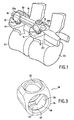
- the immobilization device bearing the general reference 10 is constituted by a first pedicle screw 12 screwed into the pedicle P1, a second pedicle screw 14 screwed into the pedicle P2, a first connecting member 16 associated with the pedicle screw 12 and a second securing member 18 associated with the pedicle screw 14.
- the immobilizing device 10 comprises an elongated connecting piece 20 which is most often called a plate.
- the connecting piece 20 is secured by each of its ends 20a, 20b pedicle screws 12 and 14 corresponding by a securing member 18, 20. It is understood that, after the establishment of 12 and 14, the surgeon, by adjusting the distance between the securing members 16 and 18, can set a spacing between the vertebrae V1 and V2 by means of the connecting piece 20.
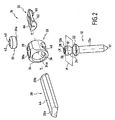
- the pedicle screw 12 which comprises a screwing body 12a and a head 12b.
- the screw has a longitudinal axis X, X 'and, preferably, the screw body 12a is connected to the head 12b by a flange 22.
- the screw head 12b has the shape of a spherical surface portion which can be divided by a plane P diametral and perpendicular to the axis X, X 'in a first portion of spherical surface 24 arranged between the plane P and the screw body 12a and a second spherical surface portion 26.
- the second spherical surface portion 26 is limited by a hexagonal or other blind hole 28 used for the establishment of the screwing tool. If we now consider the securing member 16, it consists essentially of a fastening piece 28, by a clamping member 30 and, preferably, but not necessarily, by an intermediate piece 32.
- the fastening piece 28 has the general shape of a ring constituted by a wall 34 whose inner face 34a is substantially cylindrical in revolution about an axis Y, Y '.
- This wall 34 of the piece 28 has an axial passage 36 limited by the inner face 34a and two openings respectively referenced 38 and 40 pierced in the wall 34.
- the first opening 38 has a wall 38a which is threaded or which forms part of a bayonet system.
- the opening 38 is intended to receive the clamping member 30.
- This clamping member comprises a threaded portion or constituting a bayonet system 30a and a head 40 provided, for example, with a blind hole 42 for the engagement of a screwing or tightening tool.
- the elongated connecting piece 20 has also been shown which has a substantially flat first face 44 intended to cooperate with the active part 30a of the clamping member 30.
- the part 20, or at least its ends 20a and 20b, are defined to be able to be engaged in the axial passage 36 of the fastening pieces 28.
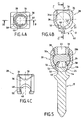
- the piece of solidarity 28 we will describe in more detail the piece of solidarity 28.
- the wall 34 of this part we find the wall 34 of this part with its cylindrical axial passage 36, its upper opening 38 intended to receive the clamping member 30 and its second opening or lower opening 40.
- the second opening 40 is constituted, in fact, by two parts respectively referenced 46 and 48 which communicate with one another and which are angularly offset around the axis Y, Y 'of the joining piece .
- the first portion 46 of the second opening 40 has the shape of a portion of a circle (substantially a semicircle) of axis ZZ 'coincides with the axis of the first opening 38.
- This opening 46 has a diameter D less than the diameter D 'of the head 26 of the screw 12.
- the rim of the opening of the portion 46 of the opening 40 constitutes a bearing surface 50, for example, in the form of a spherical surface portion.
- the second opening portion 48 has the shape of a circle portion of diameter D1 and axis T, T 'angulated by an angle ⁇ with respect to the axis Z-Z'.
- the angle a may be equal to 40 degrees.
- the diameter D1 of the second portion 48 of the opening 40 is greater than the diameter D 'of the head 26 of the screw 12.
- the contour of the second opening 40 is of course in the intersection of the portions of circles corresponding to the parts 46. and 48. It is now understood that the head 26 of the screw 12 can be freely engaged in the axial passage 36 of the fastening piece 28 through the second portion 48 of the opening 40 when the axis X, X ' of the screw coincides with the axis T, T 'of the opening portion 48.
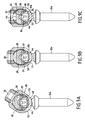
- the mounting of the immobilizing device according to the first embodiment is represented, that is to say the one in which the fastener does not comprise the intermediate part 32.
- the screw 12 is shown. engaged in the first portion 46 of the second opening 40 of the fastening piece 28.
- the first spherical surface portion 24 of the head 12b of the screw is therefore supported on the bearing 50 of this portion of the opening.
- the second face 52 of the end 20b of the connecting piece 20 comprises a longitudinal recess 54 which defines two longitudinal inclined bearing surfaces 56 and 58.
- each securing member 16, 18 further comprises an intermediate piece 32 which can be inserted into the axial passage 36 of the connecting piece 28.
- the intermediate piece 32 has a first face 60 having the shape of a cylindrical surface portion whose radius is substantially equal to that of the axial passage 36 of the fastening piece. 28.
- first face 60 is formed a recess 62 which will be described in more detail later.
- the second face 66 of the piece 32 is substantially flat.
- the piece 32 is provided with a rib 68, 70. The ribs are separated by an axial length L at least equal to the axial length of the piece 28.
- the recess 62 formed in the part 32 comprises an active part opening into the face 60 which constitutes a frustoconical surface 64 or possibly spherical.
- the useful part of the recess 62 is extended by a circular portion 72.
- the piece 32 comprises a longitudinal groove 74 arranged along the longitudinal median plane of the part to allow its elastic deformation, as will be explained later.
- the function of the intermediate piece 32 is to be inserted in the axial passage 36 of the connecting piece 28 between the head 12b of the screw 12 and the end 20a of the connecting piece 20. More precisely, the function of this piece is to transmit the clamping force exerted by the clamping member 30 on the upper face 44 of the connecting piece 20 to the second spherical portion 26 of the head of the screw 12b by cooperation of the frustoconical bearing surface 64 of the recess 62 of the piece 32 with the second spherical surface portion of the head 12b of the screw.
- the piece 20 always has a flat upper face 44 and its second face 80 is also flat and has an axial recess 82 in such a way that this face 80 defines two longitudinal plane bearing surfaces 84 and 86. As will be explained later, these bearings 84 and 86 come to bear on the flat upper face 66 of the intermediate piece 32.
- the intermediate piece 32 is pre-mounted inside the axial passage 36 of the securing piece and that the clamping member 30 is also pre-mounted on the member of solidarity.
- the screws 12 and 14 having been screwed by the surgeon into the pedicles of the vertebrae to be immobilized, the latter engages on the heads 12b of these screws the securing pieces 28 in such a way that the second portion 48 of the second opening 40 presents an axis T, T 'aligned with that of the screw 12.
- the head 12b of the screw can be freely engaged by the opening portion 48 to partially penetrate the axial passage 36. More specifically, this head 12B is housed in the inside of the recess 62 of the intermediate piece 32, the latter being in this state, free to pivot about the longitudinal axis of the fastening piece. Then, after having performed this operation for the screws 12 and 14, the surgeon sets up the elongated connecting piece 30 or, more precisely, the ends 20A and 20B of these parts could already be engaged in the fastening pieces 28.
- the piece 32 ' has a bottom face 60' in the form of a cylindrical surface sector intended to be applied against the inner wall 34 of the axial passage 36 of the fastening piece 28.
- the lower face 60 ' ends at its ends with ribs 68 'and 70' playing the same role as the ribs 68 and 70.
- a recess 62 ' which plays the same role as the recess 62 and which has a frustoconical or possibly spherical portion 64' intended to bear on the spherical head 12b of the screw 12.
- the upper face 80 'of the piece 32' has a central, semi-cylindrical bearing 82, shaped to receive the connecting rod 20 '.
- the central span 82 is extended at both ends by semi-frustoconical portions 84 and 86.
- the recess 62 ' opens at its upper end into the central span 82.
- This central span 82 could also be constituted by two symmetrical inclined plane surfaces. compared to the median plane of the room 32 '.
Landscapes
- Health & Medical Sciences (AREA)
- Orthopedic Medicine & Surgery (AREA)
- Life Sciences & Earth Sciences (AREA)
- Surgery (AREA)
- Neurology (AREA)
- General Health & Medical Sciences (AREA)
- Veterinary Medicine (AREA)
- Biomedical Technology (AREA)
- Heart & Thoracic Surgery (AREA)
- Medical Informatics (AREA)
- Molecular Biology (AREA)
- Animal Behavior & Ethology (AREA)
- Nuclear Medicine, Radiotherapy & Molecular Imaging (AREA)
- Public Health (AREA)
- Engineering & Computer Science (AREA)
- Surgical Instruments (AREA)
- Prostheses (AREA)
- Materials For Medical Uses (AREA)
- Fuel Cell (AREA)
- Clamps And Clips (AREA)
- Connection Of Plates (AREA)
- Crystals, And After-Treatments Of Crystals (AREA)
- Polarising Elements (AREA)
- Power-Operated Mechanisms For Wings (AREA)
Claims (6)
- Vorrichtung zum Festlegen von wenigstens zwei Wirbeln, mit wenigstens zwei Schrauben (12, 14), einem länglichen Verbindungsteil (20, 20') sowie wenigstens zwei Organen zum festen Verbinden (16, 18), wobei jede Schraube (12, 14) einen Einschraubkörper (12a) und einen Kopf (12b) umfaßt, welcher die Form eines Kugelteils aufweist, das von einem ersten Kugelflächenabschnitt (24), der zwischen dem Körper der Schraube und einer zur Achse des Körpers der Schraube orthogonalen Diametralebene angeordnet ist, sowie von einem zweiten Kugelflächenabschnitt (26) gebildet ist, dadurch gekennzeichnet, daß jedes Organ zum festen Verbinden (16, 18) wenigstens folgendes umfaßt:ein Klemmteil (30) undein einstückig ausgebildetes Teil zum festen Verbinden (28), das die Form eines Rings aufweist, der eine Seitenwand (34) hat, welche einen axialen Durchgang (36) umgibt, wobei die Wand eine erste Öffnung (38), welche geeignet ist, das Klemmteil aufzunehmen und mit diesem zusammenzuwirken, sowie eine zweite Öffnung (40) mit einem ersten (46) und einem zweiten Teil (48) aufweist, wobei die beiden Teile miteinander verbunden sind und gegenüber der Achse (Y, Y') des Teils zum festen Verbinden winkelmäßig versetzt sind, wobei der erste Teil eine diametrale Achse (Z, Z'), die im wesentlichen mit derjenigen der ersten Öffnung zusammenfällt, sowie einen eine Auflagefläche für den ersten Kugelflächenabschnitt (24) des Schraubenkopfes bildenden Rand (50) aufweist, wobei der zweite Teil (48) der zweiten Öffnung (40) den freien Durchgang des Kopfes der Schraube ermöglicht, wobei der axiale Durchgang geeignet ist, wenigstens ein Ende des Verbindungsteils (20, 20') und den Schraubenkopf (12b) aufzunehmen, wodurch der Kopf der Schraube über den zweiten Teil der zweiten Öffnung, durch Drehen des Teils zum festen Verbinden in den axialen Durchgang des Teils zum festen Verbinden frei einführbar ist, die Auflagefläche (50) des ersten Teils der zweiten Öffnung gegenüber dem ersten Kugelflächenabschnitt des Schraubenkopfes plaziert wird und, durch Aktivieren des Klemmteils, das Ende des Verbindungsteils und der Kopf der Schraube gegenüber dem Teil zum festen Verbinden gegen ein Drehen und Verschieben festgelegt werden.
- Festlegungsvorrichtung nach Anspruch 1, dadurch gekennzeichnet, daß das Organ zum festen Verbinden (16, 18) ferner ein Zwischenteil (32, 32') aufweist, das in den axialen Durchgang (36) des Teils zum festen Verbinden eingefügt werden kann, wobei das Zwischenteil (32, 32') eine erste Fläche (60), die geeignet ist, gegenüber der Innenseite der Wand (34) des Teils zum festen Verbinden (28) plaziert zu werden, wobei das Zwischenteil eine in die erste Fläche mündende Ausnehmung aufweist, die eine Auflagefläche für wenigstens einen Teil des zweiten Kugelflächenabschnitts (26) des Schraubenkopfes (12b) bildet, sowie eine zweite Auflagefläche (66) aufweist, die geeignet ist, mit dem Ende (20a) des Verbindungsteils (20, 20') zusammenzuwirken, wodurch dann, wenn das Zwischenteil (32) in den axialen Durchgang (36) des Verbindungsteils eingefügt ist, die durch das Klemmorgan (30) aufgebrachte Klemmkraft über das Ende des Verbindungsteils auf das Zwischenteil übertragen wird.
- Festlegungsvorrichtung nach Anspruch 1, dadurch gekennzeichnet, daß wenigstens jedes Ende (20a, 20b) des Verbindungsteils (20) eine im wesentlichen ebene erste Fläche (44) sowie eine zweite Fläche (52) umfaßt, die eine Längsausnehmung (54) aufweist, welche zwei geneigte Auflageflächen (56, 58) definiert, die geeignet sind, mit dem zweiten Kugelflächenabschnitt (26) des Schraubenkopfes (12b) zusammenzuwirken.
- Festlegungsvorrichtung nach Anspruch 2, dadurch gekennzeichnet, daß das Zwischenteil (32, 32') an jedem seiner Enden eine Rippe (68, 70) aufweist, die aus der ersten Fläche (60) hervorragt, um mit den Endflächen des Teils zum festen Verbinden (28) zusammenzuwirken, wenn das Zwischenteil (32, 32') in den axialen Durchgang (36) des Teils zum festen Verbinden (28) eingesteckt ist.
- Festlegungsvorrichtung nach einem der Ansprüche 2 und 4, dadurch gekennzeichnet, daß wenigstens jedes Ende (20a, 20b) des Verbindungsteils (20) eine im wesentlichen ebene erste Fläche (44), um mit dem Klemmorgan (30) zusammenzuwirken, sowie eine zweite Fläche (80) aufweist, die zwei im wesentlichen ebene Auflageflächen (84, 86) definiert, um mit der zweiten Fläche (66) des Zwischenteils (32) zusammenzuwirken.
- Festlegungsvorrichtung nach einem der Ansprüche 2 und 4, dadurch gekennzeichnet, daß das Verbindungsteil (20') einen kreisförmigen Querschnitt aufweist, und daß die zweite Fläche des Zwischenteils (32') eine Auflagefläche mit kreisbogenförmigem Querschnitt aufweist, die geeignet ist, ein Ende des Verbindungsteils (20') aufzunehmen.
Priority Applications (1)
| Application Number | Priority Date | Filing Date | Title |
|---|---|---|---|
| SI200331506T SI1575433T1 (sl) | 2002-10-07 | 2003-10-02 | Sistem pritrditve ploščice |
Applications Claiming Priority (5)
| Application Number | Priority Date | Filing Date | Title |
|---|---|---|---|
| FR0212397A FR2845268B1 (fr) | 2002-10-07 | 2002-10-07 | Systeme de fixation de plaque |
| FR0212397 | 2002-10-07 | ||
| FR0302503A FR2845269B1 (fr) | 2002-10-07 | 2003-02-28 | Systeme de fixation a plaque |
| FR0302503 | 2003-02-28 | ||
| PCT/FR2003/002890 WO2004032772A2 (fr) | 2002-10-07 | 2003-10-02 | Systeme de fixation a plaque |
Publications (2)
| Publication Number | Publication Date |
|---|---|
| EP1575433A2 EP1575433A2 (de) | 2005-09-21 |
| EP1575433B1 true EP1575433B1 (de) | 2008-11-05 |
Family
ID=32031846
Family Applications (1)
| Application Number | Title | Priority Date | Filing Date |
|---|---|---|---|
| EP03773815A Expired - Lifetime EP1575433B1 (de) | 2002-10-07 | 2003-10-02 | Fixierungssystem für knochenplatte |
Country Status (13)
| Country | Link |
|---|---|
| US (1) | US7503918B2 (de) |
| EP (1) | EP1575433B1 (de) |
| JP (1) | JP4309890B2 (de) |
| KR (1) | KR20050052528A (de) |
| AT (1) | ATE413144T1 (de) |
| AU (1) | AU2003282196B2 (de) |
| DE (1) | DE60324590D1 (de) |
| DK (1) | DK1575433T3 (de) |
| ES (1) | ES2316836T3 (de) |
| FR (1) | FR2845269B1 (de) |
| PT (1) | PT1575433E (de) |
| SI (1) | SI1575433T1 (de) |
| WO (1) | WO2004032772A2 (de) |
Cited By (2)
| Publication number | Priority date | Publication date | Assignee | Title |
|---|---|---|---|---|
| EP2279707A1 (de) | 2009-07-31 | 2011-02-02 | Zimmer Spine | Knochenfixierungssystem |
| EP2316363A1 (de) | 2009-10-27 | 2011-05-04 | Zimmer Spine | Knochenhaltevorrichtung |
Families Citing this family (146)
| Publication number | Priority date | Publication date | Assignee | Title |
|---|---|---|---|---|
| US7833250B2 (en) | 2004-11-10 | 2010-11-16 | Jackson Roger P | Polyaxial bone screw with helically wound capture connection |
| US6726689B2 (en) | 2002-09-06 | 2004-04-27 | Roger P. Jackson | Helical interlocking mating guide and advancement structure |
| US8377100B2 (en) | 2000-12-08 | 2013-02-19 | Roger P. Jackson | Closure for open-headed medical implant |
| US7862587B2 (en) | 2004-02-27 | 2011-01-04 | Jackson Roger P | Dynamic stabilization assemblies, tool set and method |
| US8353932B2 (en) | 2005-09-30 | 2013-01-15 | Jackson Roger P | Polyaxial bone anchor assembly with one-piece closure, pressure insert and plastic elongate member |
| US8292926B2 (en) | 2005-09-30 | 2012-10-23 | Jackson Roger P | Dynamic stabilization connecting member with elastic core and outer sleeve |
| US10729469B2 (en) | 2006-01-09 | 2020-08-04 | Roger P. Jackson | Flexible spinal stabilization assembly with spacer having off-axis core member |
| US10258382B2 (en) | 2007-01-18 | 2019-04-16 | Roger P. Jackson | Rod-cord dynamic connection assemblies with slidable bone anchor attachment members along the cord |
| US7179260B2 (en) | 2003-09-29 | 2007-02-20 | Smith & Nephew, Inc. | Bone plates and bone plate assemblies |
| US8257402B2 (en) | 2002-09-06 | 2012-09-04 | Jackson Roger P | Closure for rod receiving orthopedic implant having left handed thread removal |
| WO2006052796A2 (en) | 2004-11-10 | 2006-05-18 | Jackson Roger P | Helical guide and advancement flange with break-off extensions |
| US8876868B2 (en) | 2002-09-06 | 2014-11-04 | Roger P. Jackson | Helical guide and advancement flange with radially loaded lip |
| US8282673B2 (en) | 2002-09-06 | 2012-10-09 | Jackson Roger P | Anti-splay medical implant closure with multi-surface removal aperture |
| US8540753B2 (en) | 2003-04-09 | 2013-09-24 | Roger P. Jackson | Polyaxial bone screw with uploaded threaded shank and method of assembly and use |
| US7621918B2 (en) | 2004-11-23 | 2009-11-24 | Jackson Roger P | Spinal fixation tool set and method |
| US6716214B1 (en) | 2003-06-18 | 2004-04-06 | Roger P. Jackson | Polyaxial bone screw with spline capture connection |
| US7377923B2 (en) | 2003-05-22 | 2008-05-27 | Alphatec Spine, Inc. | Variable angle spinal screw assembly |
| US8936623B2 (en) | 2003-06-18 | 2015-01-20 | Roger P. Jackson | Polyaxial bone screw assembly |
| US8366753B2 (en) | 2003-06-18 | 2013-02-05 | Jackson Roger P | Polyaxial bone screw assembly with fixed retaining structure |
| US8137386B2 (en) | 2003-08-28 | 2012-03-20 | Jackson Roger P | Polyaxial bone screw apparatus |
| US8814911B2 (en) | 2003-06-18 | 2014-08-26 | Roger P. Jackson | Polyaxial bone screw with cam connection and lock and release insert |
| US8398682B2 (en) | 2003-06-18 | 2013-03-19 | Roger P. Jackson | Polyaxial bone screw assembly |
| US20110040338A1 (en) * | 2003-08-28 | 2011-02-17 | Jackson Roger P | Polyaxial bone anchor having an open retainer with conical, cylindrical or curvate capture |
| US7776067B2 (en) | 2005-05-27 | 2010-08-17 | Jackson Roger P | Polyaxial bone screw with shank articulation pressure insert and method |
| US8257398B2 (en) | 2003-06-18 | 2012-09-04 | Jackson Roger P | Polyaxial bone screw with cam capture |
| US7766915B2 (en) | 2004-02-27 | 2010-08-03 | Jackson Roger P | Dynamic fixation assemblies with inner core and outer coil-like member |
| US8092500B2 (en) | 2007-05-01 | 2012-01-10 | Jackson Roger P | Dynamic stabilization connecting member with floating core, compression spacer and over-mold |
| US7967850B2 (en) | 2003-06-18 | 2011-06-28 | Jackson Roger P | Polyaxial bone anchor with helical capture connection, insert and dual locking assembly |
| US8377102B2 (en) * | 2003-06-18 | 2013-02-19 | Roger P. Jackson | Polyaxial bone anchor with spline capture connection and lower pressure insert |
| US7967826B2 (en) | 2003-10-21 | 2011-06-28 | Theken Spine, Llc | Connector transfer tool for internal structure stabilization systems |
| US7588575B2 (en) | 2003-10-21 | 2009-09-15 | Innovative Spinal Technologies | Extension for use with stabilization systems for internal structures |
| US7179261B2 (en) | 2003-12-16 | 2007-02-20 | Depuy Spine, Inc. | Percutaneous access devices and bone anchor assemblies |
| US11419642B2 (en) | 2003-12-16 | 2022-08-23 | Medos International Sarl | Percutaneous access devices and bone anchor assemblies |
| US7527638B2 (en) | 2003-12-16 | 2009-05-05 | Depuy Spine, Inc. | Methods and devices for minimally invasive spinal fixation element placement |
| US8353933B2 (en) * | 2007-04-17 | 2013-01-15 | Gmedelaware 2 Llc | Facet joint replacement |
| US7160300B2 (en) | 2004-02-27 | 2007-01-09 | Jackson Roger P | Orthopedic implant rod reduction tool set and method |
| US8152810B2 (en) | 2004-11-23 | 2012-04-10 | Jackson Roger P | Spinal fixation tool set and method |
| JP2007525274A (ja) | 2004-02-27 | 2007-09-06 | ロジャー・ピー・ジャクソン | 整形外科インプラントロッド整復器具セット及び方法 |
| US11241261B2 (en) | 2005-09-30 | 2022-02-08 | Roger P Jackson | Apparatus and method for soft spinal stabilization using a tensionable cord and releasable end structure |
| US7935135B2 (en) | 2004-06-09 | 2011-05-03 | Zimmer Spine, Inc. | Spinal fixation device |
| US7651502B2 (en) | 2004-09-24 | 2010-01-26 | Jackson Roger P | Spinal fixation tool set and method for rod reduction and fastener insertion |
| US7722654B2 (en) * | 2004-10-05 | 2010-05-25 | Warsaw Orthopedic, Inc. | Spinal implants with multi-axial anchor assembly and methods |
| US8267969B2 (en) | 2004-10-20 | 2012-09-18 | Exactech, Inc. | Screw systems and methods for use in stabilization of bone structures |
| US8226690B2 (en) | 2005-07-22 | 2012-07-24 | The Board Of Trustees Of The Leland Stanford Junior University | Systems and methods for stabilization of bone structures |
| WO2006047555A2 (en) * | 2004-10-25 | 2006-05-04 | Alphaspine, Inc. | Bone fixation systems and methods |
| US8926672B2 (en) | 2004-11-10 | 2015-01-06 | Roger P. Jackson | Splay control closure for open bone anchor |
| US9168069B2 (en) | 2009-06-15 | 2015-10-27 | Roger P. Jackson | Polyaxial bone anchor with pop-on shank and winged insert with lower skirt for engaging a friction fit retainer |
| US9216041B2 (en) | 2009-06-15 | 2015-12-22 | Roger P. Jackson | Spinal connecting members with tensioned cords and rigid sleeves for engaging compression inserts |
| WO2006057837A1 (en) | 2004-11-23 | 2006-06-01 | Jackson Roger P | Spinal fixation tool attachment structure |
| US9980753B2 (en) | 2009-06-15 | 2018-05-29 | Roger P Jackson | pivotal anchor with snap-in-place insert having rotation blocking extensions |
| US7875065B2 (en) | 2004-11-23 | 2011-01-25 | Jackson Roger P | Polyaxial bone screw with multi-part shank retainer and pressure insert |
| US8308782B2 (en) | 2004-11-23 | 2012-11-13 | Jackson Roger P | Bone anchors with longitudinal connecting member engaging inserts and closures for fixation and optional angulation |
| US8444681B2 (en) | 2009-06-15 | 2013-05-21 | Roger P. Jackson | Polyaxial bone anchor with pop-on shank, friction fit retainer and winged insert |
| ATE524121T1 (de) | 2004-11-24 | 2011-09-15 | Abdou Samy | Vorrichtungen zur platzierung eines orthopädischen intervertebralen implantats |
| US9339301B2 (en) | 2004-12-30 | 2016-05-17 | Mark A. Barry | System and method for aligning vertebrae in the amelioration of aberrant spinal column deviation conditions |
| US7901437B2 (en) | 2007-01-26 | 2011-03-08 | Jackson Roger P | Dynamic stabilization member with molded connection |
| US10076361B2 (en) | 2005-02-22 | 2018-09-18 | Roger P. Jackson | Polyaxial bone screw with spherical capture, compression and alignment and retention structures |
| US8523865B2 (en) | 2005-07-22 | 2013-09-03 | Exactech, Inc. | Tissue splitter |
| US8105368B2 (en) | 2005-09-30 | 2012-01-31 | Jackson Roger P | Dynamic stabilization connecting member with slitted core and outer sleeve |
| US7704271B2 (en) | 2005-12-19 | 2010-04-27 | Abdou M Samy | Devices and methods for inter-vertebral orthopedic device placement |
| US20070191839A1 (en) * | 2006-01-27 | 2007-08-16 | Sdgi Holdings, Inc. | Non-locking multi-axial joints in a vertebral implant and methods of use |
| US20070270815A1 (en) * | 2006-04-20 | 2007-11-22 | Chris Johnson | Bone anchors with end-loading receivers for elongated connecting elements in spinal surgical procedures |
| US8876874B2 (en) * | 2006-08-21 | 2014-11-04 | M. Samy Abdou | Bone screw systems and methods of use |
| US20080177327A1 (en) * | 2006-10-17 | 2008-07-24 | Hugues Malandain | Central rod connector and T-rod |
| US8062341B2 (en) * | 2006-10-18 | 2011-11-22 | Globus Medical, Inc. | Rotatable bone plate |
| US8096996B2 (en) | 2007-03-20 | 2012-01-17 | Exactech, Inc. | Rod reducer |
| JP2010512178A (ja) | 2006-12-08 | 2010-04-22 | ロジャー・ピー・ジャクソン | 動的脊椎インプラントのためのツールシステム |
| US8366745B2 (en) | 2007-05-01 | 2013-02-05 | Jackson Roger P | Dynamic stabilization assembly having pre-compressed spacers with differential displacements |
| US7931676B2 (en) * | 2007-01-18 | 2011-04-26 | Warsaw Orthopedic, Inc. | Vertebral stabilizer |
| US8475498B2 (en) | 2007-01-18 | 2013-07-02 | Roger P. Jackson | Dynamic stabilization connecting member with cord connection |
| US8012177B2 (en) | 2007-02-12 | 2011-09-06 | Jackson Roger P | Dynamic stabilization assembly with frusto-conical connection |
| US10383660B2 (en) | 2007-05-01 | 2019-08-20 | Roger P. Jackson | Soft stabilization assemblies with pretensioned cords |
| US7947065B2 (en) | 2008-11-14 | 2011-05-24 | Ortho Innovations, Llc | Locking polyaxial ball and socket fastener |
| US7942911B2 (en) | 2007-05-16 | 2011-05-17 | Ortho Innovations, Llc | Polyaxial bone screw |
| US7951173B2 (en) | 2007-05-16 | 2011-05-31 | Ortho Innovations, Llc | Pedicle screw implant system |
| US8197518B2 (en) | 2007-05-16 | 2012-06-12 | Ortho Innovations, Llc | Thread-thru polyaxial pedicle screw system |
| US7942909B2 (en) | 2009-08-13 | 2011-05-17 | Ortho Innovations, Llc | Thread-thru polyaxial pedicle screw system |
| US7942910B2 (en) | 2007-05-16 | 2011-05-17 | Ortho Innovations, Llc | Polyaxial bone screw |
| EP2160158A4 (de) | 2007-05-31 | 2013-06-26 | Roger P Jackson | Dynamisches stabilisationsverbindungselement mit vorgespanntem festen kern |
| US8911477B2 (en) | 2007-10-23 | 2014-12-16 | Roger P. Jackson | Dynamic stabilization member with end plate support and cable core extension |
| KR100985059B1 (ko) * | 2007-11-28 | 2010-10-05 | 주식회사 솔고 바이오메디칼 | 척추 고정 장치 |
| US8257401B2 (en) * | 2008-02-12 | 2012-09-04 | Spinal U.S.A. | Bottom mounted pedical screw assembly |
| US8118837B2 (en) | 2008-07-03 | 2012-02-21 | Zimmer Spine, Inc. | Tapered-lock spinal rod connectors and methods for use |
| JPWO2010004613A1 (ja) * | 2008-07-08 | 2011-12-22 | 株式会社ロバート・リード商会 | 脊椎固定装置 |
| US8167914B1 (en) | 2008-07-16 | 2012-05-01 | Zimmer Spine, Inc. | Locking insert for spine stabilization and method of use |
| US8197512B1 (en) * | 2008-07-16 | 2012-06-12 | Zimmer Spine, Inc. | System and method for spine stabilization using resilient inserts |
| WO2010147639A1 (en) | 2008-08-01 | 2010-12-23 | Jackson Roger P | Longitudinal connecting member with sleeved tensioned cords |
| ES2392362T3 (es) * | 2008-10-08 | 2012-12-10 | Biedermann Technologies Gmbh & Co. Kg | Dispositivo de anclaje de huesos y dispositivo de estabilización para partes de hueso o vértebras |
| US20100106193A1 (en) * | 2008-10-27 | 2010-04-29 | Barry Mark A | System and method for aligning vertebrae in the amelioration of aberrant spinal column deviation conditions in patients requiring the accomodation of spinal column growth or elongation |
| WO2013043218A1 (en) | 2009-06-15 | 2013-03-28 | Jackson Roger P | Polyaxial bone anchor with pop-on shank and winged insert with friction fit compressive collet |
| US11229457B2 (en) | 2009-06-15 | 2022-01-25 | Roger P. Jackson | Pivotal bone anchor assembly with insert tool deployment |
| US8998959B2 (en) | 2009-06-15 | 2015-04-07 | Roger P Jackson | Polyaxial bone anchors with pop-on shank, fully constrained friction fit retainer and lock and release insert |
| US9668771B2 (en) | 2009-06-15 | 2017-06-06 | Roger P Jackson | Soft stabilization assemblies with off-set connector |
| EP2753252A1 (de) | 2009-06-15 | 2014-07-16 | Jackson, Roger P. | Polyaxialer knochenanker mit pop-on-schaft und presssitzfixierung mit niedrigprofilkantensperre |
| AU2010303934B2 (en) | 2009-10-05 | 2014-03-27 | Roger P. Jackson | Polyaxial bone anchor with non-pivotable retainer and pop-on shank, some with friction fit |
| US8764806B2 (en) | 2009-12-07 | 2014-07-01 | Samy Abdou | Devices and methods for minimally invasive spinal stabilization and instrumentation |
| US9381045B2 (en) | 2010-01-13 | 2016-07-05 | Jcbd, Llc | Sacroiliac joint implant and sacroiliac joint instrument for fusing a sacroiliac joint |
| US9333090B2 (en) | 2010-01-13 | 2016-05-10 | Jcbd, Llc | Systems for and methods of fusing a sacroiliac joint |
| CA3002234C (en) | 2010-01-13 | 2020-07-28 | Jcbd, Llc | Sacroiliac joint fixation fusion system |
| WO2014015309A1 (en) | 2012-07-20 | 2014-01-23 | Jcbd, Llc | Orthopedic anchoring system and methods |
| US9788961B2 (en) | 2010-01-13 | 2017-10-17 | Jcbd, Llc | Sacroiliac joint implant system |
| US9421109B2 (en) | 2010-01-13 | 2016-08-23 | Jcbd, Llc | Systems and methods of fusing a sacroiliac joint |
| US12383311B2 (en) | 2010-05-14 | 2025-08-12 | Roger P. Jackson | Pivotal bone anchor assembly and method for use thereof |
| AU2011276535B2 (en) | 2010-06-28 | 2015-03-12 | K2M, Inc. | Spinal stabilization system |
| WO2012030712A1 (en) | 2010-08-30 | 2012-03-08 | Zimmer Spine, Inc. | Polyaxial pedicle screw |
| JP2013540468A (ja) | 2010-09-08 | 2013-11-07 | ロジャー・ピー・ジャクソン | 弾性部および非弾性部を有する動的固定化部材 |
| JP2013545527A (ja) | 2010-11-02 | 2013-12-26 | ロジャー・ピー・ジャクソン | ポップオン式シャンクと枢動可能な保持部とを有する多軸の骨アンカー |
| US9358122B2 (en) | 2011-01-07 | 2016-06-07 | K2M, Inc. | Interbody spacer |
| WO2012128825A1 (en) | 2011-03-24 | 2012-09-27 | Jackson Roger P | Polyaxial bone anchor with compound articulation and pop-on shank |
| US8845728B1 (en) | 2011-09-23 | 2014-09-30 | Samy Abdou | Spinal fixation devices and methods of use |
| JP2014533136A (ja) | 2011-10-05 | 2014-12-11 | マーク・エイ・ドッドソン | モジュール開創器および関連する方法 |
| US8911479B2 (en) | 2012-01-10 | 2014-12-16 | Roger P. Jackson | Multi-start closures for open implants |
| US20130226240A1 (en) | 2012-02-22 | 2013-08-29 | Samy Abdou | Spinous process fixation devices and methods of use |
| US9198767B2 (en) | 2012-08-28 | 2015-12-01 | Samy Abdou | Devices and methods for spinal stabilization and instrumentation |
| US9545270B2 (en) | 2012-10-15 | 2017-01-17 | K2M, Inc. | Universal rod holder |
| US9320617B2 (en) | 2012-10-22 | 2016-04-26 | Cogent Spine, LLC | Devices and methods for spinal stabilization and instrumentation |
| US9827018B2 (en) | 2012-11-13 | 2017-11-28 | K2M, Inc. | Spinal stabilization system |
| US9186182B2 (en) | 2012-11-13 | 2015-11-17 | K2M, Inc. | Spinal stabilization system |
| US9168068B2 (en) | 2012-11-13 | 2015-10-27 | K2M, Inc. | Spinal stabilization system |
| US9095378B2 (en) | 2012-11-13 | 2015-08-04 | K2M, Inc. | Spinal stabilization system |
| US9801662B2 (en) | 2012-11-13 | 2017-10-31 | K2M, Inc. | Spinal stabilization system |
| US8911478B2 (en) | 2012-11-21 | 2014-12-16 | Roger P. Jackson | Splay control closure for open bone anchor |
| US10058354B2 (en) | 2013-01-28 | 2018-08-28 | Roger P. Jackson | Pivotal bone anchor assembly with frictional shank head seating surfaces |
| US8852239B2 (en) | 2013-02-15 | 2014-10-07 | Roger P Jackson | Sagittal angle screw with integral shank and receiver |
| US10245087B2 (en) | 2013-03-15 | 2019-04-02 | Jcbd, Llc | Systems and methods for fusing a sacroiliac joint and anchoring an orthopedic appliance |
| US9510872B2 (en) | 2013-03-15 | 2016-12-06 | Jcbd, Llc | Spinal stabilization system |
| US9717539B2 (en) | 2013-07-30 | 2017-08-01 | Jcbd, Llc | Implants, systems, and methods for fusing a sacroiliac joint |
| US9826986B2 (en) | 2013-07-30 | 2017-11-28 | Jcbd, Llc | Systems for and methods of preparing a sacroiliac joint for fusion |
| ES2603204T3 (es) * | 2013-07-19 | 2017-02-24 | Biedermann Technologies Gmbh & Co. Kg | Dispositivo de anclaje de hueso poliaxial |
| WO2015017593A1 (en) | 2013-07-30 | 2015-02-05 | Jcbd, Llc | Systems for and methods of fusing a sacroiliac joint |
| US9566092B2 (en) | 2013-10-29 | 2017-02-14 | Roger P. Jackson | Cervical bone anchor with collet retainer and outer locking sleeve |
| EP2881054B1 (de) | 2013-12-06 | 2019-09-04 | K2M, Inc. | Wirbelsäulenstabilisierungssystem mit geformter Wirbelsäulenstange |
| US9717533B2 (en) | 2013-12-12 | 2017-08-01 | Roger P. Jackson | Bone anchor closure pivot-splay control flange form guide and advancement structure |
| US9451993B2 (en) | 2014-01-09 | 2016-09-27 | Roger P. Jackson | Bi-radial pop-on cervical bone anchor |
| AU2015246029B2 (en) * | 2014-04-10 | 2018-11-29 | Medacta International Sa | Device for fixing surgical implants in place and relative assembly procedure with anchoring means |
| US9801546B2 (en) | 2014-05-27 | 2017-10-31 | Jcbd, Llc | Systems for and methods of diagnosing and treating a sacroiliac joint disorder |
| US9597119B2 (en) | 2014-06-04 | 2017-03-21 | Roger P. Jackson | Polyaxial bone anchor with polymer sleeve |
| US10064658B2 (en) | 2014-06-04 | 2018-09-04 | Roger P. Jackson | Polyaxial bone anchor with insert guides |
| US10149702B2 (en) | 2015-01-12 | 2018-12-11 | Imds Llc | Polyaxial screw and rod system |
| US10857003B1 (en) | 2015-10-14 | 2020-12-08 | Samy Abdou | Devices and methods for vertebral stabilization |
| US10973648B1 (en) | 2016-10-25 | 2021-04-13 | Samy Abdou | Devices and methods for vertebral bone realignment |
| US10744000B1 (en) | 2016-10-25 | 2020-08-18 | Samy Abdou | Devices and methods for vertebral bone realignment |
| WO2018209186A1 (en) * | 2017-05-11 | 2018-11-15 | Marc Evan Richelsoph | Advanced polyaxial system and surgical procedure |
| US10603055B2 (en) | 2017-09-15 | 2020-03-31 | Jcbd, Llc | Systems for and methods of preparing and fusing a sacroiliac joint |
| US11179248B2 (en) | 2018-10-02 | 2021-11-23 | Samy Abdou | Devices and methods for spinal implantation |
| EP4346660A4 (de) | 2021-06-30 | 2025-07-09 | Mark A Dodson | Verankerungsvorrichtung |
Family Cites Families (16)
| Publication number | Priority date | Publication date | Assignee | Title |
|---|---|---|---|---|
| DE9109883U1 (de) * | 1991-08-09 | 1991-09-26 | Howmedica GmbH, 2314 Schönkirchen | Verriegelungsnagel zur Versorgung von Femurfrakturen im mittleren und im trochanteren Bereich |
| US5443464A (en) * | 1993-02-16 | 1995-08-22 | Memphis Orthopaedic Design, Inc. | External fixator apparatus |
| DE4307576C1 (de) * | 1993-03-10 | 1994-04-21 | Biedermann Motech Gmbh | Knochenschraube |
| US6712073B2 (en) * | 1995-06-26 | 2004-03-30 | Easton L. Manderson | Extramedullary rod implant for long bones |
| FR2747034B1 (fr) * | 1996-04-03 | 1998-06-19 | Scient X | Systeme de contention et de fusion intersomatique |
| US5782833A (en) * | 1996-12-20 | 1998-07-21 | Haider; Thomas T. | Pedicle screw system for osteosynthesis |
| FR2771918B1 (fr) * | 1997-12-09 | 2000-04-21 | Dimso Sa | Connecteur pour dispositif d'osteosynthese rachidienne |
| US5938662A (en) * | 1998-02-24 | 1999-08-17 | Beere Precision Medical Instruments, Inc. | Human spine fixation template and method of making same |
| DE19936286C2 (de) * | 1999-08-02 | 2002-01-17 | Lutz Biedermann | Knochenschraube |
| US6443953B1 (en) * | 2000-02-08 | 2002-09-03 | Cross Medical Products, Inc. | Self-aligning cap nut for use with a spinal rod anchor |
| FR2812535B3 (fr) * | 2000-08-01 | 2002-09-20 | Henry Graf | Dispositif destine a etre implante dans au moins une vertebre, et utilisation de ce dispositif |
| AU2002235349B2 (en) * | 2001-01-12 | 2006-05-18 | Depuy Spine, Inc. | Polyaxial screw with improved locking |
| DE10115014A1 (de) * | 2001-03-27 | 2002-10-24 | Biedermann Motech Gmbh | Verankerungselement |
| FR2827757A1 (fr) * | 2001-07-27 | 2003-01-31 | Sra | Piece et dispositif pour materiel d'immobilisation relative de deux vertebres |
| DE10136129A1 (de) * | 2001-07-27 | 2003-02-20 | Biedermann Motech Gmbh | Knochenschraube und Befestigungswerkzeug für diese |
| TW200518711A (en) * | 2003-12-11 | 2005-06-16 | A Spine Holding Group Corp | Rotation buckling ball-head spine restoring equipment |
-
2003
- 2003-02-28 FR FR0302503A patent/FR2845269B1/fr not_active Expired - Fee Related
- 2003-10-02 AU AU2003282196A patent/AU2003282196B2/en not_active Ceased
- 2003-10-02 KR KR1020057005947A patent/KR20050052528A/ko not_active Abandoned
- 2003-10-02 ES ES03773815T patent/ES2316836T3/es not_active Expired - Lifetime
- 2003-10-02 DE DE60324590T patent/DE60324590D1/de not_active Expired - Lifetime
- 2003-10-02 DK DK03773815T patent/DK1575433T3/da active
- 2003-10-02 PT PT03773815T patent/PT1575433E/pt unknown
- 2003-10-02 AT AT03773815T patent/ATE413144T1/de not_active IP Right Cessation
- 2003-10-02 US US10/530,509 patent/US7503918B2/en not_active Expired - Fee Related
- 2003-10-02 EP EP03773815A patent/EP1575433B1/de not_active Expired - Lifetime
- 2003-10-02 SI SI200331506T patent/SI1575433T1/sl unknown
- 2003-10-02 JP JP2005500989A patent/JP4309890B2/ja not_active Expired - Fee Related
- 2003-10-02 WO PCT/FR2003/002890 patent/WO2004032772A2/fr not_active Ceased
Cited By (5)
| Publication number | Priority date | Publication date | Assignee | Title |
|---|---|---|---|---|
| EP2279707A1 (de) | 2009-07-31 | 2011-02-02 | Zimmer Spine | Knochenfixierungssystem |
| WO2011012690A1 (en) | 2009-07-31 | 2011-02-03 | Zimmer Spine | Bone fixing system |
| EP3045128A1 (de) | 2009-07-31 | 2016-07-20 | Zimmer Spine | Knochenfixierungssystem |
| EP2316363A1 (de) | 2009-10-27 | 2011-05-04 | Zimmer Spine | Knochenhaltevorrichtung |
| WO2011051316A2 (en) | 2009-10-27 | 2011-05-05 | Zimmer Spine | Bone holding device |
Also Published As
| Publication number | Publication date |
|---|---|
| JP2006503677A (ja) | 2006-02-02 |
| US7503918B2 (en) | 2009-03-17 |
| FR2845269B1 (fr) | 2005-06-24 |
| JP4309890B2 (ja) | 2009-08-05 |
| DE60324590D1 (de) | 2008-12-18 |
| WO2004032772A2 (fr) | 2004-04-22 |
| AU2003282196B2 (en) | 2008-06-05 |
| AU2003282196A1 (en) | 2004-05-04 |
| KR20050052528A (ko) | 2005-06-02 |
| DK1575433T3 (da) | 2009-03-09 |
| EP1575433A2 (de) | 2005-09-21 |
| ATE413144T1 (de) | 2008-11-15 |
| US20050273099A1 (en) | 2005-12-08 |
| ES2316836T3 (es) | 2009-04-16 |
| FR2845269A1 (fr) | 2004-04-09 |
| WO2004032772A3 (fr) | 2005-10-06 |
| SI1575433T1 (sl) | 2009-04-30 |
| PT1575433E (pt) | 2009-02-06 |
Similar Documents
| Publication | Publication Date | Title |
|---|---|---|
| EP1575433B1 (de) | Fixierungssystem für knochenplatte | |
| EP1011504B1 (de) | Vorrichtung zur osteosynthese die ein verbindungselement der wirbelsaülenstange und der verankerungselemente aufweist | |
| EP1467666B1 (de) | Verbindungsstück für ein wirbelverankerungssystem | |
| EP0814716B1 (de) | Hilfsvorrichtung für die wirbelsäulenosteosynthese, insbesondere zum gebrauch mitverbindungsstangen | |
| EP0773746B1 (de) | Stabbefestigungsvorrichtung für spinale orthopädische zwecke | |
| EP1663035B1 (de) | Wirbelsäulenimplantat | |
| FR2857850A1 (fr) | Materiel d'osteosynthese vertebrale | |
| CA2377028A1 (fr) | Organe d'ancrage avec une bague de securite | |
| FR2925288A1 (fr) | Dispositif de connexion pivotant pour vis d'osteosynthese rachidienne | |
| WO1998049960A1 (fr) | Systeme d'osteosynthese pour arthrodese vertebrale | |
| EP1080692A1 (de) | Anpassungsfähige Verbindung für Knochenverankerungsmittel | |
| FR2856578A1 (fr) | Materiel d'osteosynthese vertebrale | |
| EP1478292A1 (de) | Verbindungsvorrichtung zwischen einem stab und einem kugelförmigen scharaubenkopf | |
| FR2865377A1 (fr) | Materiel d'osteosynthese vertebrale | |
| EP1198205A1 (de) | Osteosynthetische polyaxialverbindung | |
| FR2861980A1 (fr) | Systeme d'implant comprenant un implant et un moyen de fixation de l'implant pourvu d'une vis d'ancrage vissee dans un organe de blocage clippe dans l'implant | |
| WO2012013868A1 (fr) | Perfectionnements pour dispositif d'arthroplastie facettaire | |
| EP2869774B1 (de) | Polyaxiale schraube mit einem mechanischen gewinde und reibungsvorrichtung dafür | |
| EP1571971A2 (de) | Vorrichtung zur verbindung eines teiles auf einen träger und verfahren zu dessen errichtung | |
| FR2845268A1 (fr) | Systeme de fixation de plaque | |
| FR2775582A1 (fr) | Organe d'osteosynthese rachidien pour la fixation d'un ligament | |
| FR2763828A1 (fr) | Systeme a plaque d'osteosynthese vertebrale | |
| FR2958531A1 (fr) | Dispositif d'indexation par pivot et rainure de la poly axialite d'une vis pediculaire | |
| WO1996031167A1 (fr) | Dispositif pour le redressement et l'etaiement d'un rachis | |
| WO2021144515A1 (fr) | Système de fixation amovible sur un mât pour un appareil medical non implantable |
Legal Events
| Date | Code | Title | Description |
|---|---|---|---|
| PUAI | Public reference made under article 153(3) epc to a published international application that has entered the european phase |
Free format text: ORIGINAL CODE: 0009012 |
|
| 17P | Request for examination filed |
Effective date: 20050407 |
|
| AK | Designated contracting states |
Kind code of ref document: A2 Designated state(s): AT BE BG CH CY CZ DE DK EE ES FI FR GB GR HU IE IT LI LU MC NL PT RO SE SI SK TR |
|
| AX | Request for extension of the european patent |
Extension state: AL LT LV MK |
|
| PUAK | Availability of information related to the publication of the international search report |
Free format text: ORIGINAL CODE: 0009015 |
|
| AK | Designated contracting states |
Kind code of ref document: A3 Designated state(s): AT BE BG CH CY CZ DE DK EE ES FI FR GB GR HU IE IT LI LU MC NL PT RO SE SI SK TR |
|
| AX | Request for extension of the european patent |
Extension state: AL LT LV MK |
|
| RAP1 | Party data changed (applicant data changed or rights of an application transferred) |
Owner name: ABBOTT SPINE |
|
| DAX | Request for extension of the european patent (deleted) | ||
| GRAP | Despatch of communication of intention to grant a patent |
Free format text: ORIGINAL CODE: EPIDOSNIGR1 |
|
| GRAS | Grant fee paid |
Free format text: ORIGINAL CODE: EPIDOSNIGR3 |
|
| GRAA | (expected) grant |
Free format text: ORIGINAL CODE: 0009210 |
|
| AK | Designated contracting states |
Kind code of ref document: B1 Designated state(s): AT BE BG CH CY CZ DE DK EE ES FI FR GB GR HU IE IT LI LU MC NL PT RO SE SI SK TR |
|
| REG | Reference to a national code |
Ref country code: GB Ref legal event code: FG4D Free format text: NOT ENGLISH |
|
| REG | Reference to a national code |
Ref country code: CH Ref legal event code: EP |
|
| REG | Reference to a national code |
Ref country code: IE Ref legal event code: FG4D Free format text: LANGUAGE OF EP DOCUMENT: FRENCH |
|
| REF | Corresponds to: |
Ref document number: 60324590 Country of ref document: DE Date of ref document: 20081218 Kind code of ref document: P |
|
| REG | Reference to a national code |
Ref country code: CH Ref legal event code: NV Representative=s name: MICHELI & CIE SA Ref country code: RO Ref legal event code: EPE |
|
| REG | Reference to a national code |
Ref country code: PT Ref legal event code: SC4A Free format text: AVAILABILITY OF NATIONAL TRANSLATION Effective date: 20090127 |
|
| REG | Reference to a national code |
Ref country code: GR Ref legal event code: EP Ref document number: 20090400193 Country of ref document: GR |
|
| REG | Reference to a national code |
Ref country code: SE Ref legal event code: TRGR |
|
| REG | Reference to a national code |
Ref country code: DK Ref legal event code: T3 |
|
| REG | Reference to a national code |
Ref country code: EE Ref legal event code: FG4A Ref document number: E002829 Country of ref document: EE Effective date: 20090202 |
|
| REG | Reference to a national code |
Ref country code: ES Ref legal event code: FG2A Ref document number: 2316836 Country of ref document: ES Kind code of ref document: T3 |
|
| PG25 | Lapsed in a contracting state [announced via postgrant information from national office to epo] |
Ref country code: AT Free format text: LAPSE BECAUSE OF FAILURE TO SUBMIT A TRANSLATION OF THE DESCRIPTION OR TO PAY THE FEE WITHIN THE PRESCRIBED TIME-LIMIT Effective date: 20081105 |
|
| PG25 | Lapsed in a contracting state [announced via postgrant information from national office to epo] |
Ref country code: FI Free format text: LAPSE BECAUSE OF FAILURE TO SUBMIT A TRANSLATION OF THE DESCRIPTION OR TO PAY THE FEE WITHIN THE PRESCRIBED TIME-LIMIT Effective date: 20081105 |
|
| PG25 | Lapsed in a contracting state [announced via postgrant information from national office to epo] |
Ref country code: BG Free format text: LAPSE BECAUSE OF FAILURE TO SUBMIT A TRANSLATION OF THE DESCRIPTION OR TO PAY THE FEE WITHIN THE PRESCRIBED TIME-LIMIT Effective date: 20090205 |
|
| REG | Reference to a national code |
Ref country code: HU Ref legal event code: AG4A Ref document number: E005391 Country of ref document: HU |
|
| PLBE | No opposition filed within time limit |
Free format text: ORIGINAL CODE: 0009261 |
|
| STAA | Information on the status of an ep patent application or granted ep patent |
Free format text: STATUS: NO OPPOSITION FILED WITHIN TIME LIMIT |
|
| 26N | No opposition filed |
Effective date: 20090806 |
|
| REG | Reference to a national code |
Ref country code: FR Ref legal event code: CJ Ref country code: FR Ref legal event code: CD |
|
| BERE | Be: lapsed |
Owner name: ABBOTT SPINE Effective date: 20091031 |
|
| REG | Reference to a national code |
Ref country code: NL Ref legal event code: V1 Effective date: 20100501 |
|
| PG25 | Lapsed in a contracting state [announced via postgrant information from national office to epo] |
Ref country code: MC Free format text: LAPSE BECAUSE OF NON-PAYMENT OF DUE FEES Effective date: 20091031 |
|
| EUG | Se: european patent has lapsed | ||
| REG | Reference to a national code |
Ref country code: DK Ref legal event code: EBP |
|
| REG | Reference to a national code |
Ref country code: EE Ref legal event code: MM4A Ref document number: E002829 Country of ref document: EE Effective date: 20091031 |
|
| REG | Reference to a national code |
Ref country code: SI Ref legal event code: KO00 Effective date: 20100527 |
|
| REG | Reference to a national code |
Ref country code: SK Ref legal event code: MM4A Ref document number: E 5903 Country of ref document: SK Effective date: 20091002 |
|
| REG | Reference to a national code |
Ref country code: PT Ref legal event code: MM4A Free format text: LAPSE DUE TO NON-PAYMENT OF FEES Effective date: 20100705 |
|
| PG25 | Lapsed in a contracting state [announced via postgrant information from national office to epo] |
Ref country code: HU Free format text: LAPSE BECAUSE OF NON-PAYMENT OF DUE FEES Effective date: 20091003 Ref country code: NL Free format text: LAPSE BECAUSE OF NON-PAYMENT OF DUE FEES Effective date: 20100501 Ref country code: EE Free format text: LAPSE BECAUSE OF NON-PAYMENT OF DUE FEES Effective date: 20091031 |
|
| PG25 | Lapsed in a contracting state [announced via postgrant information from national office to epo] |
Ref country code: CZ Free format text: LAPSE BECAUSE OF NON-PAYMENT OF DUE FEES Effective date: 20091002 Ref country code: SI Free format text: LAPSE BECAUSE OF NON-PAYMENT OF DUE FEES Effective date: 20091003 Ref country code: SK Free format text: LAPSE BECAUSE OF NON-PAYMENT OF DUE FEES Effective date: 20091002 |
|
| PG25 | Lapsed in a contracting state [announced via postgrant information from national office to epo] |
Ref country code: IE Free format text: LAPSE BECAUSE OF NON-PAYMENT OF DUE FEES Effective date: 20091002 Ref country code: GR Free format text: LAPSE BECAUSE OF NON-PAYMENT OF DUE FEES Effective date: 20100504 Ref country code: BE Free format text: LAPSE BECAUSE OF NON-PAYMENT OF DUE FEES Effective date: 20091031 |
|
| PGFP | Annual fee paid to national office [announced via postgrant information from national office to epo] |
Ref country code: GB Payment date: 20100923 Year of fee payment: 8 |
|
| PG25 | Lapsed in a contracting state [announced via postgrant information from national office to epo] |
Ref country code: PT Free format text: LAPSE BECAUSE OF NON-PAYMENT OF DUE FEES Effective date: 20100705 Ref country code: DK Free format text: LAPSE BECAUSE OF NON-PAYMENT OF DUE FEES Effective date: 20091031 |
|
| PG25 | Lapsed in a contracting state [announced via postgrant information from national office to epo] |
Ref country code: RO Free format text: LAPSE BECAUSE OF NON-PAYMENT OF DUE FEES Effective date: 20081105 |
|
| REG | Reference to a national code |
Ref country code: ES Ref legal event code: FD2A Effective date: 20110330 |
|
| PG25 | Lapsed in a contracting state [announced via postgrant information from national office to epo] |
Ref country code: IT Free format text: LAPSE BECAUSE OF NON-PAYMENT OF DUE FEES Effective date: 20091002 |
|
| PG25 | Lapsed in a contracting state [announced via postgrant information from national office to epo] |
Ref country code: LU Free format text: LAPSE BECAUSE OF NON-PAYMENT OF DUE FEES Effective date: 20091002 |
|
| PG25 | Lapsed in a contracting state [announced via postgrant information from national office to epo] |
Ref country code: SE Free format text: LAPSE BECAUSE OF NON-PAYMENT OF DUE FEES Effective date: 20091003 |
|
| PG25 | Lapsed in a contracting state [announced via postgrant information from national office to epo] |
Ref country code: ES Free format text: LAPSE BECAUSE OF NON-PAYMENT OF DUE FEES Effective date: 20110317 |
|
| PG25 | Lapsed in a contracting state [announced via postgrant information from national office to epo] |
Ref country code: CY Free format text: LAPSE BECAUSE OF FAILURE TO SUBMIT A TRANSLATION OF THE DESCRIPTION OR TO PAY THE FEE WITHIN THE PRESCRIBED TIME-LIMIT Effective date: 20081105 Ref country code: ES Free format text: LAPSE BECAUSE OF NON-PAYMENT OF DUE FEES Effective date: 20091003 |
|
| GBPC | Gb: european patent ceased through non-payment of renewal fee |
Effective date: 20111002 |
|
| PG25 | Lapsed in a contracting state [announced via postgrant information from national office to epo] |
Ref country code: GB Free format text: LAPSE BECAUSE OF NON-PAYMENT OF DUE FEES Effective date: 20111002 |
|
| PG25 | Lapsed in a contracting state [announced via postgrant information from national office to epo] |
Ref country code: TR Free format text: LAPSE BECAUSE OF FAILURE TO SUBMIT A TRANSLATION OF THE DESCRIPTION OR TO PAY THE FEE WITHIN THE PRESCRIBED TIME-LIMIT Effective date: 20081105 |
|
| PGFP | Annual fee paid to national office [announced via postgrant information from national office to epo] |
Ref country code: CH Payment date: 20131014 Year of fee payment: 11 |
|
| REG | Reference to a national code |
Ref country code: CH Ref legal event code: PL |
|
| PG25 | Lapsed in a contracting state [announced via postgrant information from national office to epo] |
Ref country code: LI Free format text: LAPSE BECAUSE OF NON-PAYMENT OF DUE FEES Effective date: 20141031 Ref country code: CH Free format text: LAPSE BECAUSE OF NON-PAYMENT OF DUE FEES Effective date: 20141031 |
|
| REG | Reference to a national code |
Ref country code: FR Ref legal event code: PLFP Year of fee payment: 14 |
|
| REG | Reference to a national code |
Ref country code: FR Ref legal event code: PLFP Year of fee payment: 15 |
|
| PGFP | Annual fee paid to national office [announced via postgrant information from national office to epo] |
Ref country code: FR Payment date: 20170918 Year of fee payment: 15 |
|
| PGFP | Annual fee paid to national office [announced via postgrant information from national office to epo] |
Ref country code: DE Payment date: 20170927 Year of fee payment: 15 |
|
| REG | Reference to a national code |
Ref country code: DE Ref legal event code: R119 Ref document number: 60324590 Country of ref document: DE |
|
| PG25 | Lapsed in a contracting state [announced via postgrant information from national office to epo] |
Ref country code: DE Free format text: LAPSE BECAUSE OF NON-PAYMENT OF DUE FEES Effective date: 20190501 |
|
| PG25 | Lapsed in a contracting state [announced via postgrant information from national office to epo] |
Ref country code: FR Free format text: LAPSE BECAUSE OF NON-PAYMENT OF DUE FEES Effective date: 20181031 |