EP1575433B1 - Plate fixing system - Google Patents
Plate fixing system Download PDFInfo
- Publication number
- EP1575433B1 EP1575433B1 EP03773815A EP03773815A EP1575433B1 EP 1575433 B1 EP1575433 B1 EP 1575433B1 EP 03773815 A EP03773815 A EP 03773815A EP 03773815 A EP03773815 A EP 03773815A EP 1575433 B1 EP1575433 B1 EP 1575433B1
- Authority
- EP
- European Patent Office
- Prior art keywords
- face
- screw
- fastening
- piece
- screw head
- Prior art date
- Legal status (The legal status is an assumption and is not a legal conclusion. Google has not performed a legal analysis and makes no representation as to the accuracy of the status listed.)
- Expired - Lifetime
Links
Images


Classifications
-
- A—HUMAN NECESSITIES
- A61—MEDICAL OR VETERINARY SCIENCE; HYGIENE
- A61B—DIAGNOSIS; SURGERY; IDENTIFICATION
- A61B17/00—Surgical instruments, devices or methods, e.g. tourniquets
- A61B17/56—Surgical instruments or methods for treatment of bones or joints; Devices specially adapted therefor
- A61B17/58—Surgical instruments or methods for treatment of bones or joints; Devices specially adapted therefor for osteosynthesis, e.g. bone plates, screws, setting implements or the like
- A61B17/68—Internal fixation devices, including fasteners and spinal fixators, even if a part thereof projects from the skin
- A61B17/70—Spinal positioners or stabilisers ; Bone stabilisers comprising fluid filler in an implant
- A61B17/7001—Screws or hooks combined with longitudinal elements which do not contact vertebrae
- A61B17/7035—Screws or hooks, wherein a rod-clamping part and a bone-anchoring part can pivot relative to each other
- A61B17/7037—Screws or hooks, wherein a rod-clamping part and a bone-anchoring part can pivot relative to each other wherein pivoting is blocked when the rod is clamped
-
- A—HUMAN NECESSITIES
- A61—MEDICAL OR VETERINARY SCIENCE; HYGIENE
- A61B—DIAGNOSIS; SURGERY; IDENTIFICATION
- A61B17/00—Surgical instruments, devices or methods, e.g. tourniquets
- A61B17/56—Surgical instruments or methods for treatment of bones or joints; Devices specially adapted therefor
- A61B17/58—Surgical instruments or methods for treatment of bones or joints; Devices specially adapted therefor for osteosynthesis, e.g. bone plates, screws, setting implements or the like
- A61B17/68—Internal fixation devices, including fasteners and spinal fixators, even if a part thereof projects from the skin
- A61B17/70—Spinal positioners or stabilisers ; Bone stabilisers comprising fluid filler in an implant
- A61B17/7001—Screws or hooks combined with longitudinal elements which do not contact vertebrae
- A61B17/7002—Longitudinal elements, e.g. rods
- A61B17/701—Longitudinal elements with a non-circular, e.g. rectangular, cross-section
Definitions
- the present invention relates to an immobilization system of at least two vertebrae relative to each other.
- the present invention relates to a mechanical system that can be used by a surgeon to be mounted on two or more vertebrae of the spine to relatively immobilize these two vertebrae.
- Such systems are in themselves known. They are constituted by two pedicle screws which are screwed into the pedicle of the two vertebrae to be immobilized and by an elongate piece, most often called a plate whose ends are fixed on the heads of the two screws by mechanical securing members in such a way that thus, the distance between the heads of the screws and thus the distance between the two vertebrae remains fixed.
- the screw heads are spherical to form with the corresponding fastening member a swiveling system which allows the mounting of the plate regardless of the relative direction of the two screws without introducing stress on the screws, and therefore on the vertebrae in which these are fixed.
- a swiveling system which allows the mounting of the plate regardless of the relative direction of the two screws without introducing stress on the screws, and therefore on the vertebrae in which these are fixed.
- An object of the present invention is to provide an immobilization system of at least two vertebrae of the type mentioned above which better fulfills the two conditions set forth above.
- the securing system of the head of the pedicle screw and the elongate connecting piece is really effective.
- the head of the pedicle screw is plated with a suitable force on the bearing which surrounds the first part of the second opening under the effect of the clamping member, the axis of the clamping member and the axis of the opening having the scope being substantially merged.
- a securing piece which is formed in one piece, confers several advantages: on the one hand, this avoids the surgeon's need to assemble a large number of parts under delicate operating conditions and, on the other hand, the ring formed in one piece can have a smooth outer profile and regular, essentially free of asperities that could damage nearby human tissues.
- each connecting member can be easily engaged on the head of the screw, thanks to at the second part of the second opening and that the locking of the head of the screw, in the securing member, is also easy since it is sufficient to rotate the securing member and to activate the clamping member .
- each fastening member further comprises an intermediate piece insertable in the axial passage of the fastening piece, said intermediate piece having a first face adapted to be placed opposite the inner face of the wall of the fastening piece, said intermediate piece having a recess, opening into said first face, forming a bearing surface for at least a portion of said second spherical surface portion of the screw head, and a second bearing face adapted to to cooperate with the end of the connecting piece, whereby when said intermediate piece is inserted into the axial passage of the connecting piece, the clamping force developed by the clamping member is transmitted to said intermediate piece by intermediate of the end of the connecting piece.
- the tightening of the head of the screw on the bearing surface is performed by the clamping member via the intermediate piece.
- the presence of this intermediate piece improves the quality of the contact between the intermediate piece which receives the clamping force developed by the clamping member and the spherical head of the pedicle screw.
- the intermediate piece may be pre-mounted in the axial passage of the fastening piece before use. The presence of this piece does not make it more difficult to use the relative immobilization system of the vertebrae.
- the immobilization device bearing the general reference 10 is constituted by a first pedicle screw 12 screwed into the pedicle P1, a second pedicle screw 14 screwed into the pedicle P2, a first connecting member 16 associated with the pedicle screw 12 and a second securing member 18 associated with the pedicle screw 14.
- the immobilizing device 10 comprises an elongated connecting piece 20 which is most often called a plate.
- the connecting piece 20 is secured by each of its ends 20a, 20b pedicle screws 12 and 14 corresponding by a securing member 18, 20. It is understood that, after the establishment of 12 and 14, the surgeon, by adjusting the distance between the securing members 16 and 18, can set a spacing between the vertebrae V1 and V2 by means of the connecting piece 20.
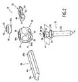
- the pedicle screw 12 which comprises a screwing body 12a and a head 12b.
- the screw has a longitudinal axis X, X 'and, preferably, the screw body 12a is connected to the head 12b by a flange 22.
- the screw head 12b has the shape of a spherical surface portion which can be divided by a plane P diametral and perpendicular to the axis X, X 'in a first portion of spherical surface 24 arranged between the plane P and the screw body 12a and a second spherical surface portion 26.
- the second spherical surface portion 26 is limited by a hexagonal or other blind hole 28 used for the establishment of the screwing tool. If we now consider the securing member 16, it consists essentially of a fastening piece 28, by a clamping member 30 and, preferably, but not necessarily, by an intermediate piece 32.
- the fastening piece 28 has the general shape of a ring constituted by a wall 34 whose inner face 34a is substantially cylindrical in revolution about an axis Y, Y '.
- This wall 34 of the piece 28 has an axial passage 36 limited by the inner face 34a and two openings respectively referenced 38 and 40 pierced in the wall 34.
- the first opening 38 has a wall 38a which is threaded or which forms part of a bayonet system.
- the opening 38 is intended to receive the clamping member 30.
- This clamping member comprises a threaded portion or constituting a bayonet system 30a and a head 40 provided, for example, with a blind hole 42 for the engagement of a screwing or tightening tool.
- the elongated connecting piece 20 has also been shown which has a substantially flat first face 44 intended to cooperate with the active part 30a of the clamping member 30.
- the part 20, or at least its ends 20a and 20b, are defined to be able to be engaged in the axial passage 36 of the fastening pieces 28.
- the piece of solidarity 28 we will describe in more detail the piece of solidarity 28.
- the wall 34 of this part we find the wall 34 of this part with its cylindrical axial passage 36, its upper opening 38 intended to receive the clamping member 30 and its second opening or lower opening 40.
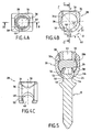
- the second opening 40 is constituted, in fact, by two parts respectively referenced 46 and 48 which communicate with one another and which are angularly offset around the axis Y, Y 'of the joining piece .
- the first portion 46 of the second opening 40 has the shape of a portion of a circle (substantially a semicircle) of axis ZZ 'coincides with the axis of the first opening 38.
- This opening 46 has a diameter D less than the diameter D 'of the head 26 of the screw 12.
- the rim of the opening of the portion 46 of the opening 40 constitutes a bearing surface 50, for example, in the form of a spherical surface portion.
- the second opening portion 48 has the shape of a circle portion of diameter D1 and axis T, T 'angulated by an angle ⁇ with respect to the axis Z-Z'.
- the angle a may be equal to 40 degrees.
- the diameter D1 of the second portion 48 of the opening 40 is greater than the diameter D 'of the head 26 of the screw 12.
- the contour of the second opening 40 is of course in the intersection of the portions of circles corresponding to the parts 46. and 48. It is now understood that the head 26 of the screw 12 can be freely engaged in the axial passage 36 of the fastening piece 28 through the second portion 48 of the opening 40 when the axis X, X ' of the screw coincides with the axis T, T 'of the opening portion 48.
- the mounting of the immobilizing device according to the first embodiment is represented, that is to say the one in which the fastener does not comprise the intermediate part 32.
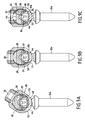
- the screw 12 is shown. engaged in the first portion 46 of the second opening 40 of the fastening piece 28.
- the first spherical surface portion 24 of the head 12b of the screw is therefore supported on the bearing 50 of this portion of the opening.
- the second face 52 of the end 20b of the connecting piece 20 comprises a longitudinal recess 54 which defines two longitudinal inclined bearing surfaces 56 and 58.
- each securing member 16, 18 further comprises an intermediate piece 32 which can be inserted into the axial passage 36 of the connecting piece 28.
- the intermediate piece 32 has a first face 60 having the shape of a cylindrical surface portion whose radius is substantially equal to that of the axial passage 36 of the fastening piece. 28.
- first face 60 is formed a recess 62 which will be described in more detail later.
- the second face 66 of the piece 32 is substantially flat.
- the piece 32 is provided with a rib 68, 70. The ribs are separated by an axial length L at least equal to the axial length of the piece 28.
- the recess 62 formed in the part 32 comprises an active part opening into the face 60 which constitutes a frustoconical surface 64 or possibly spherical.
- the useful part of the recess 62 is extended by a circular portion 72.
- the piece 32 comprises a longitudinal groove 74 arranged along the longitudinal median plane of the part to allow its elastic deformation, as will be explained later.
- the function of the intermediate piece 32 is to be inserted in the axial passage 36 of the connecting piece 28 between the head 12b of the screw 12 and the end 20a of the connecting piece 20. More precisely, the function of this piece is to transmit the clamping force exerted by the clamping member 30 on the upper face 44 of the connecting piece 20 to the second spherical portion 26 of the head of the screw 12b by cooperation of the frustoconical bearing surface 64 of the recess 62 of the piece 32 with the second spherical surface portion of the head 12b of the screw.
- the piece 20 always has a flat upper face 44 and its second face 80 is also flat and has an axial recess 82 in such a way that this face 80 defines two longitudinal plane bearing surfaces 84 and 86. As will be explained later, these bearings 84 and 86 come to bear on the flat upper face 66 of the intermediate piece 32.
- the intermediate piece 32 is pre-mounted inside the axial passage 36 of the securing piece and that the clamping member 30 is also pre-mounted on the member of solidarity.
- the screws 12 and 14 having been screwed by the surgeon into the pedicles of the vertebrae to be immobilized, the latter engages on the heads 12b of these screws the securing pieces 28 in such a way that the second portion 48 of the second opening 40 presents an axis T, T 'aligned with that of the screw 12.
- the head 12b of the screw can be freely engaged by the opening portion 48 to partially penetrate the axial passage 36. More specifically, this head 12B is housed in the inside of the recess 62 of the intermediate piece 32, the latter being in this state, free to pivot about the longitudinal axis of the fastening piece. Then, after having performed this operation for the screws 12 and 14, the surgeon sets up the elongated connecting piece 30 or, more precisely, the ends 20A and 20B of these parts could already be engaged in the fastening pieces 28.
- the piece 32 ' has a bottom face 60' in the form of a cylindrical surface sector intended to be applied against the inner wall 34 of the axial passage 36 of the fastening piece 28.
- the lower face 60 ' ends at its ends with ribs 68 'and 70' playing the same role as the ribs 68 and 70.
- a recess 62 ' which plays the same role as the recess 62 and which has a frustoconical or possibly spherical portion 64' intended to bear on the spherical head 12b of the screw 12.
- the upper face 80 'of the piece 32' has a central, semi-cylindrical bearing 82, shaped to receive the connecting rod 20 '.
- the central span 82 is extended at both ends by semi-frustoconical portions 84 and 86.
- the recess 62 ' opens at its upper end into the central span 82.
- This central span 82 could also be constituted by two symmetrical inclined plane surfaces. compared to the median plane of the room 32 '.
Landscapes
- Health & Medical Sciences (AREA)
- Orthopedic Medicine & Surgery (AREA)
- Life Sciences & Earth Sciences (AREA)
- Surgery (AREA)
- Neurology (AREA)
- General Health & Medical Sciences (AREA)
- Veterinary Medicine (AREA)
- Biomedical Technology (AREA)
- Heart & Thoracic Surgery (AREA)
- Medical Informatics (AREA)
- Molecular Biology (AREA)
- Animal Behavior & Ethology (AREA)
- Nuclear Medicine, Radiotherapy & Molecular Imaging (AREA)
- Public Health (AREA)
- Engineering & Computer Science (AREA)
- Surgical Instruments (AREA)
- Prostheses (AREA)
- Materials For Medical Uses (AREA)
- Crystals, And After-Treatments Of Crystals (AREA)
- Polarising Elements (AREA)
- Fuel Cell (AREA)
- Clamps And Clips (AREA)
- Connection Of Plates (AREA)
- Power-Operated Mechanisms For Wings (AREA)
Abstract
Description
La présente invention a pour objet un système d'immobilisation d'au moins deux vertèbres l'une par rapport à l'autre.The present invention relates to an immobilization system of at least two vertebrae relative to each other.
De façon plus précise, la présente invention concerne un système mécanique qui peut être utilisé par un chirurgien pour être monté sur deux ou plus de deux vertèbres de la colonne vertébrale afin d'immobiliser relativement ces deux vertèbres.More specifically, the present invention relates to a mechanical system that can be used by a surgeon to be mounted on two or more vertebrae of the spine to relatively immobilize these two vertebrae.
De tels systèmes sont en soi connus. Ils sont constitués par deux vis pédiculaires qui sont vissées dans le pédicule des deux vertèbres à immobiliser et par une pièce allongée, le plus souvent appelée plaque dont les extrémités sont fixées sur les têtes des deux vis par des organes mécaniques de solidarisation de telle manière qu'ainsi, la distance entre les têtes des vis et donc la distance entre les deux vertèbres reste fixe.Such systems are in themselves known. They are constituted by two pedicle screws which are screwed into the pedicle of the two vertebrae to be immobilized and by an elongate piece, most often called a plate whose ends are fixed on the heads of the two screws by mechanical securing members in such a way that thus, the distance between the heads of the screws and thus the distance between the two vertebrae remains fixed.
Le plus souvent, les têtes de vis sont sphériques pour former avec l'organe de solidarisation correspondant un système rotulant qui permet le montage de la plaque quelle que soit la direction relative des deux vis sans introduire de contrainte sur les vis, et donc sur les vertèbres dans lesquelles celles-ci sont fixées. Un tel système est connu de la demande de brevet
On comprend qu'une des qualités que doit présenter un tel système est que la solidarisation de la plaque et des vis soit suffisamment efficace pour qu'elle puisse absorber les efforts résultants des mouvements du patient qui porte le système d'immobilisation. D'autre part, il est bien sûr souhaitable que la mise en place de ce système soit aussi aisée que possible pour le chirurgien et que cette mise en place demande un temps d'intervention aussi réduit que possible.It is understood that one of the qualities that must present such a system is that the securing of the plate and the screws is sufficiently effective so that it can absorb the resulting efforts of the movements of the patient who carries the immobilization system. On the other hand, it is of course desirable that the establishment of this system is as easy as possible for the surgeon and that this implementation requires as little intervention time as possible.
Un objet de la présente invention est de fournir un système d'immobilisation d'au moins deux vertèbres du type mentionné ci-dessus qui remplisse mieux les deux conditions énoncées ci-dessus.An object of the present invention is to provide an immobilization system of at least two vertebrae of the type mentioned above which better fulfills the two conditions set forth above.
Pour atteindre ce but, selon l'invention, le dispositif d'immobilisation d'au moins deux vertèbres comprenant au moins deux vis, une pièce allongée de liaison et au moins deux organes de solidarisation, chaque vis comprenant un corps de vissage et une tête ayant la forme d'une partie de sphère constituée par une première portion de surface sphérique disposée entre le corps de la vis et un plan diamétral orthogonal à l'axe du corps de la vis et une deuxième portion de surface sphérique ; caractérisé en ce que
chaque organe de solidarisation comprend au moins :
- une pièce de serrage ; et
- une pièce de solidarisation formée d'une seule pièce ayant la forme d'une bague ayant une paroi latérale entourant un passage axial, ladite paroi comportant une première ouverture apte à recevoir ladite pièce de serrage et à coopérer avec elle et une deuxième ouverture comportant une première et une deuxième partie, lesdites deux parties communiquant entre elles et étant angulairement décalées par rapport à l'axe (Y,Y') de la pièce de solidarisation, ladite première partie présentant un axe diamétral (Z, Z') sensiblement confondu avec celui de ladite première ouverture et un rebord formant une portée pour ladite première portion de surface sphérique de la tête de vis, ladite deuxième partie de la deuxième ouverture permettant le libre passage de la tête de la vis, ledit passage axial étant apte à recevoir au moins une extrémité de ladite pièce de liaison et ladite tête de vis, par quoi, la tête de la vis peut être librement introduite dans le passage axial de la pièce de solidarisation, par ladite deuxième partie de la deuxième ouverture, par rotation de ladite pièce de solidarisation, la portée de la première partie de la deuxième ouverture est amenée en regard de la première portion de surface sphérique de la tête de vis, et, par activation de la pièce de serrage, l'extrémité de la pièce de liaison et la tête de la vis sont immobilisées en rotation et en translation par rapport à ladite pièce de solidarisation.
each fastener comprises at least:
- a clamping piece; and
- a one-piece integrally formed fastener having the shape of a ring having a side wall surrounding an axial passage, said wall having a first opening adapted to receive said clamp member and cooperating therewith and a second opening having a first and second parts, said two parts communicating with each other and being angularly offset with respect to the axis (Y, Y ') of the fastening piece, said first part having a diametral axis (Z, Z') substantially coinciding with that of said first opening and a flange forming a seat for said first spherical surface portion of the screw head, said second portion of the second opening allowing the free passage of the head of the screw, said axial passage being adapted to receive at the at least one end of said connecting piece and said screw head, whereby the head of the screw can be freely inserted into the passage axial of the securing piece, by said second portion of the second opening, by rotation of said securing piece, the bearing surface of the first portion of the second opening is brought opposite the first spherical surface portion of the screw head and, by activating the clamping piece, the end of the connecting piece and the head of the screw are immobilized in rotation and in translation relative to said securing piece.
On comprend que, d'une part, le système de solidarisation de la tête de la vis pédiculaire et de la pièce de liaison allongée est réellement efficace. En effet, la tête de la vis pédiculaire est plaquée avec une force convenable sur la portée qui entoure la première partie de la deuxième ouverture sous l'effet de l'organe de serrage, l'axe de l'organe de serrage et l'axe de l'ouverture comportant la portée étant sensiblement confondus.It is understood that, on the one hand, the securing system of the head of the pedicle screw and the elongate connecting piece is really effective. Indeed, the head of the pedicle screw is plated with a suitable force on the bearing which surrounds the first part of the second opening under the effect of the clamping member, the axis of the clamping member and the axis of the opening having the scope being substantially merged.
On comprend en outre qu'une pièce de solidarisation, qui est formée d'une seule pièce, confère plusieurs avantages : d'une part, cela évite au chirurgien la nécessité d'assembler un nombre important de pièces dans des conditions opératoires délicates et, d'autre part, la bague formée d'une seule pièce peut présenter un profil extérieur lisse et régulier, essentiellement exempt d'aspérités qui risqueraient d'endommager les tissus humains avoisinants.It is furthermore understood that a securing piece, which is formed in one piece, confers several advantages: on the one hand, this avoids the surgeon's need to assemble a large number of parts under delicate operating conditions and, on the other hand, the ring formed in one piece can have a smooth outer profile and regular, essentially free of asperities that could damage nearby human tissues.
On comprend également que la mise en place de ce système d'immobilisation est relativement aisé puisque, après le vissage des vis pédiculaires dans les pédicules des deux vertèbres à immobiliser, chaque organe de liaison peut être aisément engagé sur la tête de la vis, grâce à la deuxième partie de la deuxième ouverture et que le verrouillage de la tête de la vis, dans l'organe de solidarisation, est également aisé puisqu'il suffit de faire pivoter l'organe de solidarisation et d'activer l'organe de serrage.It is also understood that the establishment of this immobilization system is relatively easy since, after screwing the pedicle screws in the pedicles of the two vertebrae to be immobilized, each connecting member can be easily engaged on the head of the screw, thanks to at the second part of the second opening and that the locking of the head of the screw, in the securing member, is also easy since it is sufficient to rotate the securing member and to activate the clamping member .
Selon un mode préféré de mise en oeuvre, chaque organe de solidarisation comprend, en outre, une pièce intermédiaire insérable dans le passage axial de la pièce de solidarisation, ladite pièce intermédiaire présentant une première face apte à être mise en regard de la face interne de la paroi de la pièce de solidarisation, ladite pièce intermédiaire présentant un évidement, débouchant dans ladite première face, formant une portée pour au moins une partie de ladite deuxième portion de surface sphérique de la tête de vis, et une deuxième face d'appui apte à coopérer avec l'extrémité de la pièce de liaison, par quoi, lorsque ladite pièce intermédiaire est insérée dans le passage axial de la pièce de liaison, la force de serrage développée par l'organe de serrage est transmise à ladite pièce intermédiaire par l'intermédiaire de l'extrémité de la pièce de liaison.According to a preferred embodiment, each fastening member further comprises an intermediate piece insertable in the axial passage of the fastening piece, said intermediate piece having a first face adapted to be placed opposite the inner face of the wall of the fastening piece, said intermediate piece having a recess, opening into said first face, forming a bearing surface for at least a portion of said second spherical surface portion of the screw head, and a second bearing face adapted to to cooperate with the end of the connecting piece, whereby when said intermediate piece is inserted into the axial passage of the connecting piece, the clamping force developed by the clamping member is transmitted to said intermediate piece by intermediate of the end of the connecting piece.
On comprend que dans ce mode de réalisation préférentiel, le serrage de la tête de la vis sur la portée d'appui est réalisé par l'organe de serrage via la pièce intermédiaire. La présence de cette pièce intermédiaire permet d'améliorer la qualité du contact entre cette pièce intermédiaire qui reçoit la force de serrage développée par l'organe de serrage et la tête sphérique de la vis pédiculaire. Selon un mode préféré de réalisation de cette variante, la pièce intermédiaire peut être pré-montée dans le passage axial de la pièce de solidarisation avant son utilisation. La présence de cette pièce ne rend donc pas plus complexe l'utilisation du système d'immobilisation relative des vertèbres.It is understood that in this preferred embodiment, the tightening of the head of the screw on the bearing surface is performed by the clamping member via the intermediate piece. The presence of this intermediate piece improves the quality of the contact between the intermediate piece which receives the clamping force developed by the clamping member and the spherical head of the pedicle screw. According to a preferred embodiment of this variant, the intermediate piece may be pre-mounted in the axial passage of the fastening piece before use. The presence of this piece does not make it more difficult to use the relative immobilization system of the vertebrae.
D'autres caractéristiques et avantages de l'invention apparaîtront mieux à la lecture de la description qui suit de plusieurs modes de réalisation de l'invention donnés à titre d'exemple non limitatif. La description se réfère aux figures annexées sur lesquelles :
- la
figure 1 est une vue en perspective montrant l'implantation du système d'immobilisation sur les vertèbres ; - la
figure 2 est une vue éclatée montrant les différents composants du système d'immobilisation ; - la
figure 3 est une vue en perspective de la pièce de solidarisation ; - la
figure 4A est une vue de dessus de la pièce de solidarisation ; - la
figure 4B est une vue en coupe selon la ligne B-B de lafigure 4A ; - la
figure 4C est une vue en coupe selon la ligne C-C de lafigure 4B ; - la
figure 5 est une vue en coupe verticale montrant la solidarisation d'une vis et de la pièce de liaison, selon un premier mode de mise en oeuvre de l'invention ; - la
figure 6 est une vue en perspective de la pièce intermédiaire selon une première variante de réalisation ; - la
figure 7A est une vue de dessus de la pièce intermédiaire de lafigure 6 ; - la
figure 7B est une vue en coupe selon la ligne B-B de lafigure 7A ; - la
figure 7C est une vue en coupe selon la ligne C-C de lafigure 7A ; - la
figure 8A est une vue en coupe longitudinale de la pièce de liaison selon une première variante de réalisation ; - la
figure 8B est une vue de dessous de la pièce de liaison de lafigure 8A ; - la
figure 8C est une vue en coupe selon la ligne C-C de lafigure 8A ; - les
figures 9A, 9B et 9C illustrent le mode de solidarisation d'une vis avec la pièce de liaison, selon le mode perfectionné de mise en oeuvre de l'invention ; - la
figure 10 est une vue en perspective d'une deuxième variante de réalisation du système de solidarisation ; - la
figure 11A est une vue en perspective d'une variante de réalisation de la pièce intermédiaire ; - la
figure 11B est une vue de dessus de la pièce intermédiaire de lafigure 11A ; - la
figure 11C est une vue en coupe selon la ligne C-C de lafigure 11B ; - la
figure 11D est une vue en coupe selon la ligne D-D de lafigure 11B ; et - la
figure 12 est une vue en élévation de la variante de réalisation montrée sur lafigure 10 .
- the
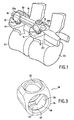
figure 1 is a perspective view showing the implantation of the immobilization system on the vertebrae; - the
figure 2 is an exploded view showing the various components of the immobilizer system; - the
figure 3 is a perspective view of the fastening piece; - the
Figure 4A is a top view of the fastening piece; - the
Figure 4B is a sectional view along line BB of theFigure 4A ; - the
figure 4C is a sectional view along the line CC of theFigure 4B ; - the
figure 5 is a vertical sectional view showing the fastening of a screw and the connecting piece, according to a first embodiment of the invention; - the
figure 6 is a perspective view of the intermediate piece according to a first embodiment; - the
Figure 7A is a top view of the middle piece of thefigure 6 ; - the
Figure 7B is a sectional view along line BB of theFigure 7A ; - the
Figure 7C is a sectional view along the line CC of theFigure 7A ; - the
figure 8A is a longitudinal sectional view of the connecting piece according to a first embodiment; - the
Figure 8B is a bottom view of the connecting piece of thefigure 8A ; - the
Figure 8C is a sectional view along the line CC of thefigure 8A ; - the
Figures 9A, 9B and 9C illustrate the method of securing a screw with the connecting piece, according to the improved mode of implementation of the invention; - the
figure 10 is a perspective view of a second variant embodiment of the fastening system; - the
figure 11A is a perspective view of an alternative embodiment of the intermediate piece; - the
Figure 11B is a top view of the middle piece of thefigure 11A ; - the
figure 11C is a sectional view along the line CC of theFigure 11B ; - the
figure 11D is a sectional view along the line DD of theFigure 11B ; and - the
figure 12 is an elevational view of the alternative embodiment shown on thefigure 10 .
En se référant tout d'abord à la
Sur cette figure, on a représenté une première vertèbre V1 avec son pédicule P1 ainsi qu'une deuxième vertèbre adjacente V2 avec son pédicule P2. Le dispositif d'immobilisation portant la référence générale 10 est constitué par une première vis pédiculaire 12 vissée dans le pédicule P1, une deuxième vis pédiculaire 14 vissée dans le pédicule P2, un premier organe de liaison 16 associé à la vis pédiculaire 12 et un deuxième organe de solidarisation 18 associé à la vis pédiculaire 14. Enfin, le dispositif d'immobilisation 10 comporte une pièce allongée de liaison 20 qui est le plus souvent appelée plaque. Comme le montre cette figure, la pièce de liaison 20 est rendue solidaire par chacune de ses extrémités 20a, 20b des vis pédiculaires 12 et 14 correspondante par un organe de solidarisation 18, 20. On comprend qu'ainsi, après la mise en place des vis 12 et 14, le chirurgien, en réglant la distance entre les organes de solidarisation 16 et 18, peut fixer un écartement entre les vertèbres V1 et V2 à l'aide de la pièce de liaison 20.In this figure, there is shown a first vertebra V1 with its pedicle P1 and a second adjacent vertebra V2 with its pedicle P2. The immobilization device bearing the
En se référant maintenant à la
La pièce de solidarisation 28 a la forme générale d'une bague constituée par une paroi 34 dont la face interne 34a est sensiblement cylindrique de révolution autour d'un axe Y, Y'. Cette paroi 34 de la pièce 28 présente un passage axial 36 limité par la face interne 34a et deux ouvertures respectivement référencées 38 et 40 percées dans la paroi 34.The
La première ouverture 38 présente une paroi 38a qui est filetée ou qui constitue une partie d'un système à baïonnette. L'ouverture 38 est destinée à recevoir l'organe de serrage 30. Cet organe de serrage comporte une partie filetée ou constituant un système à baïonnette 30a et une tête 40 munie, par exemple, d'un trou borgne 42 pour l'engagement d'un outil de vissage ou de serrage. Sur la
En se référant maintenant aux
Comme le montrent mieux les
Sur la
Selon un mode perfectionné de réalisation du dispositif d'immobilisation, chaque organe de solidarisation 16, 18 comporte en outre une pièce intermédiaire 32 qui peut être insérée dans le passage axial 36 de la pièce de liaison 28.According to an improved embodiment of the immobilizing device, each securing
En se référant maintenant aux
Comme le montre mieux la
La fonction de la pièce intermédiaire 32 est d'être insérée dans le passage axial 36 de la pièce de liaison 28 entre la tête 12b de la vis 12 et l'extrémité 20a de la pièce de liaison 20. Plus précisément, la fonction de cette pièce est de transmettre la force de serrage exercée par l'organe de serrage 30 sur la face supérieure 44 de la pièce de liaison 20 à la deuxième portion sphérique 26 de la tête de la vis 12b par coopération de la portée tronconique 64 de l'évidement 62 de la pièce 32 avec la deuxième portion de surface sphérique de la tête 12b de la vis.The function of the
En se référant aux
En se référant maintenant aux
Il faut tout d'abord préciser que, de préférence, la pièce intermédiaire 32 est pré-montée à l'intérieur du passage axial 36 de la pièce de solidarisation et que l'organe de serrage 30 est également pré-monté sur l'organe de solidarisation.It should first be pointed out that, preferably, the
Les vis 12 et 14 ayant été vissées par le chirurgien dans les pédicules des vertèbres à immobiliser, celui-ci engage, sur les têtes 12b de ces vis les pièces de solidarisation 28 de telle manière que la deuxième partie 48 de la deuxième ouverture 40 présente un axe T,T' aligné avec celui de la vis 12. La tête 12b de la vis peut être librement engagée par la portion d'ouverture 48 pour pénétrer partiellement dans le passage axial 36. Plus précisément, cette tête 12B vient se loger à l'intérieur de l'évidement 62 de la pièce intermédiaire 32, celle-ci étant dans cet état, libre de pivoter autour de l'axe longitudinal de la pièce de solidarisation. Ensuite, après avoir réalisé cette opération pour les vis 12 et 14, le chirurgien met en place la pièce de liaison allongée 30 ou, plus précisément, les extrémités 20A et 20B de ces pièces ont pu être déjà engagées dans les pièces de solidarisation 28.The
Ces opérations ayant été réalisées, le chirurgien provoque le pivotement de la pièce de solidarisation 28 autour de son axe longitudinal de l'angle a afin d'amener l'axe Z,Z' de la première partie 46 de l'ouverture 40 en alignement avec celui de la vis 12. C'est ce qui est représenté sur la
En se référant maintenant aux
Cette variante se distingue du mode de mise en oeuvre déjà décrit par le fait que l'organe allongé de liaison qui porte la référence 20' sur la
En revanche, les vis 12, l'organe de vissage 30 et la pièce de solidarisation 28 ne sont pas modifiés. Ils ne seront donc pas décrits à nouveau.On the other hand, the
En se référant plus particulièrement aux
Dans la face inférieure 60' de la pièce 32' est ménagé un évidement 62' qui joue le même rôle que l'évidement 62 et qui comporte une partie tronconique ou éventuellement sphérique 64' destinée à venir en appui sur la tête sphérique 12b de la vis 12.In the lower face 60 'of the piece 32' is formed a recess 62 'which plays the same role as the
La face supérieure 80' de la pièce 32' comporte une portée centrale, semi-cylindrique 82, conformée pour recevoir la tige de liaison 20'. La portée centrale 82 se prolonge à ses deux extrémités par des parties semi-tronconiques 84 et 86. L'évidement 62' débouche à son extrémité supérieure dans la portée centrale 82. Cette portée centrale 82 pourrait également être constituée par deux surfaces planes inclinées symétriques par rapport au plan médian de la pièce 32'.The upper face 80 'of the piece 32' has a central,
L'utilisation de ce mode de réalisation est sensiblement identique à celui du mode de réalisation illustré sur les
Il résulte de la description précédente du mode de mise en oeuvre du système de solidarisation, que celui-ci permet une mise en place aisée du système tout en permettant l'adaptation nécessaire de la direction de la pièce de liaison par rapport aux vis et en assurant une solidarisation et une immobilisation efficace des vis et de la pièce de liaison.It follows from the previous description of the embodiment of the fastening system, that it allows easy installation of the system while allowing the necessary adaptation of the direction of the connecting piece with respect to the screws and ensuring a securing and effective immobilization of the screws and the connecting piece.
Claims (6)
- A system for immobilizing two or more vertebrae, which system comprises two or more screws (12, 14), an elongate connecting member (20, 20') and two or more fastening systems (16, 18), each screw (12, 14) comprising a screw body (12a) and a screw head (12b) having the shape of a portion of a sphere consisting of a first spherical surface portion (24) between the screw body and a diametral plane orthogonal to the axis of the screw body and a second spherical surface portion (26); characterized in that
each fastening system (16, 18) comprises at least:- a clamping member (30); and- a fastening member (28) formed in one piece having the shape of a ring having a lateral wall (34) around an axial passage (36), said wall including a first aperture (38) adapted to receive and to cooperate with said clamping member and a second aperture (40) having a first portion (46) and a second portion (48), said two portions communicating with each other and being angularly offset relative to the axis (Y, Y') of the fastening member, said first portion having a diametral axis (Z, Z') substantially coinciding with that of said first aperture and a rim (50) forming a bearing surface for said first spherical surface portion (24) of the screw head, said second portion (48) of the second aperture (40) allowing the screw head to pass through it, said axial passage being adapted to receive at least one end of said connecting member (20, 20') and said screw head (12b), whereby the screw head may be freely introduced into the axial passage of the fastening member via said second portion of the second aperture by rotating said fastening member, the bearing surface (50) of the first portion of the second aperture is made to face the first spherical surface portion of the screw head and, by activation of the clamping member, the end of the connecting member and the screw head are immobilized against rotation and against movement in translation relative to said fastening member. - An immobilization system according to claim 1, characterized in that said fastening system (16, 18) further comprises an intermediate member (32, 32') adapted to be inserted into the axial passage (36) of the fastening member and having a first face (60) adapted to be made to face the internal face of the wall (34) of the fastening member (28), a recess opening onto said first face, forming a bearing surface for at least a portion of said second spherical surface portion (26) of the screw head (12b), and a second bearing face (66) adapted to cooperate with the ends (20a) of the connecting member (20, 20') whereby, when said intermediate member (32) is inserted into the axial passage (36) of the connecting member, the clamping force produced by the clamping member (30) is transmitted to said intermediate member via the end of the connecting member.
- An immobilization system according to claim 1, characterized in that each end (20a, 20b) of said connecting member (20) has a substantially plane first face (44) and a second face (52) including a longitudinal recess (54) defining two inclined bearing surfaces (56, 58) adapted to cooperate with the second spherical surface portion (26) of the screw head (12b).
- An immobilization system according to claim 2,
characterized in that said intermediate member (32, 32') has at each end a rib (68, 70) projecting from its first face (60) to cooperate with the end faces of said fastening member (28) when the intermediate member (32, 32') is engaged in the axial passage (36) of the fastening member (28). - An immobilization system according to claim 2 or claim 4, characterized in that each end (20a, 20b) of the connecting member (20) has a substantially plane first face (44) for cooperating with the clamping member (30) and a second face (80) defining two substantially plane bearing surfaces (84, 86) for cooperating with the second face (66) of said intermediate member (32).
- An immobilization system according to claim 2 or claim 4, characterized in that said connecting member (20') has a circular cross-section and in that said second face of the intermediate member (32') includes a bearing surface that has a cross-section in the shape of a circular arc adapted to receive an end of said connecting member (20').
Priority Applications (1)
| Application Number | Priority Date | Filing Date | Title |
|---|---|---|---|
| SI200331506T SI1575433T1 (en) | 2002-10-07 | 2003-10-02 | Plate fixing system |
Applications Claiming Priority (5)
| Application Number | Priority Date | Filing Date | Title |
|---|---|---|---|
| FR0212397 | 2002-10-07 | ||
| FR0212397A FR2845268B1 (en) | 2002-10-07 | 2002-10-07 | PLATE FASTENING SYSTEM |
| FR0302503A FR2845269B1 (en) | 2002-10-07 | 2003-02-28 | PLATE FASTENING SYSTEM |
| FR0302503 | 2003-02-28 | ||
| PCT/FR2003/002890 WO2004032772A2 (en) | 2002-10-07 | 2003-10-02 | Plate fixing system |
Publications (2)
| Publication Number | Publication Date |
|---|---|
| EP1575433A2 EP1575433A2 (en) | 2005-09-21 |
| EP1575433B1 true EP1575433B1 (en) | 2008-11-05 |
Family
ID=32031846
Family Applications (1)
| Application Number | Title | Priority Date | Filing Date |
|---|---|---|---|
| EP03773815A Expired - Lifetime EP1575433B1 (en) | 2002-10-07 | 2003-10-02 | Plate fixing system |
Country Status (13)
| Country | Link |
|---|---|
| US (1) | US7503918B2 (en) |
| EP (1) | EP1575433B1 (en) |
| JP (1) | JP4309890B2 (en) |
| KR (1) | KR20050052528A (en) |
| AT (1) | ATE413144T1 (en) |
| AU (1) | AU2003282196B2 (en) |
| DE (1) | DE60324590D1 (en) |
| DK (1) | DK1575433T3 (en) |
| ES (1) | ES2316836T3 (en) |
| FR (1) | FR2845269B1 (en) |
| PT (1) | PT1575433E (en) |
| SI (1) | SI1575433T1 (en) |
| WO (1) | WO2004032772A2 (en) |
Cited By (2)
| Publication number | Priority date | Publication date | Assignee | Title |
|---|---|---|---|---|
| EP2279707A1 (en) | 2009-07-31 | 2011-02-02 | Zimmer Spine | Bone fixing system |
| EP2316363A1 (en) | 2009-10-27 | 2011-05-04 | Zimmer Spine | Bone holding device |
Families Citing this family (144)
| Publication number | Priority date | Publication date | Assignee | Title |
|---|---|---|---|---|
| US7833250B2 (en) | 2004-11-10 | 2010-11-16 | Jackson Roger P | Polyaxial bone screw with helically wound capture connection |
| US6726689B2 (en) | 2002-09-06 | 2004-04-27 | Roger P. Jackson | Helical interlocking mating guide and advancement structure |
| US8377100B2 (en) | 2000-12-08 | 2013-02-19 | Roger P. Jackson | Closure for open-headed medical implant |
| US8292926B2 (en) | 2005-09-30 | 2012-10-23 | Jackson Roger P | Dynamic stabilization connecting member with elastic core and outer sleeve |
| US10258382B2 (en) | 2007-01-18 | 2019-04-16 | Roger P. Jackson | Rod-cord dynamic connection assemblies with slidable bone anchor attachment members along the cord |
| US7862587B2 (en) | 2004-02-27 | 2011-01-04 | Jackson Roger P | Dynamic stabilization assemblies, tool set and method |
| US10729469B2 (en) | 2006-01-09 | 2020-08-04 | Roger P. Jackson | Flexible spinal stabilization assembly with spacer having off-axis core member |
| US8353932B2 (en) * | 2005-09-30 | 2013-01-15 | Jackson Roger P | Polyaxial bone anchor assembly with one-piece closure, pressure insert and plastic elongate member |
| US7179260B2 (en) | 2003-09-29 | 2007-02-20 | Smith & Nephew, Inc. | Bone plates and bone plate assemblies |
| US8876868B2 (en) | 2002-09-06 | 2014-11-04 | Roger P. Jackson | Helical guide and advancement flange with radially loaded lip |
| WO2006052796A2 (en) | 2004-11-10 | 2006-05-18 | Jackson Roger P | Helical guide and advancement flange with break-off extensions |
| US8257402B2 (en) | 2002-09-06 | 2012-09-04 | Jackson Roger P | Closure for rod receiving orthopedic implant having left handed thread removal |
| US8282673B2 (en) | 2002-09-06 | 2012-10-09 | Jackson Roger P | Anti-splay medical implant closure with multi-surface removal aperture |
| US6716214B1 (en) | 2003-06-18 | 2004-04-06 | Roger P. Jackson | Polyaxial bone screw with spline capture connection |
| US7621918B2 (en) | 2004-11-23 | 2009-11-24 | Jackson Roger P | Spinal fixation tool set and method |
| US8540753B2 (en) | 2003-04-09 | 2013-09-24 | Roger P. Jackson | Polyaxial bone screw with uploaded threaded shank and method of assembly and use |
| US7377923B2 (en) | 2003-05-22 | 2008-05-27 | Alphatec Spine, Inc. | Variable angle spinal screw assembly |
| US8814911B2 (en) | 2003-06-18 | 2014-08-26 | Roger P. Jackson | Polyaxial bone screw with cam connection and lock and release insert |
| US8926670B2 (en) | 2003-06-18 | 2015-01-06 | Roger P. Jackson | Polyaxial bone screw assembly |
| US8377102B2 (en) | 2003-06-18 | 2013-02-19 | Roger P. Jackson | Polyaxial bone anchor with spline capture connection and lower pressure insert |
| US7776067B2 (en) | 2005-05-27 | 2010-08-17 | Jackson Roger P | Polyaxial bone screw with shank articulation pressure insert and method |
| US8092500B2 (en) | 2007-05-01 | 2012-01-10 | Jackson Roger P | Dynamic stabilization connecting member with floating core, compression spacer and over-mold |
| US7967850B2 (en) | 2003-06-18 | 2011-06-28 | Jackson Roger P | Polyaxial bone anchor with helical capture connection, insert and dual locking assembly |
| US8137386B2 (en) | 2003-08-28 | 2012-03-20 | Jackson Roger P | Polyaxial bone screw apparatus |
| US8398682B2 (en) | 2003-06-18 | 2013-03-19 | Roger P. Jackson | Polyaxial bone screw assembly |
| US20110040338A1 (en) * | 2003-08-28 | 2011-02-17 | Jackson Roger P | Polyaxial bone anchor having an open retainer with conical, cylindrical or curvate capture |
| US8257398B2 (en) | 2003-06-18 | 2012-09-04 | Jackson Roger P | Polyaxial bone screw with cam capture |
| US8366753B2 (en) | 2003-06-18 | 2013-02-05 | Jackson Roger P | Polyaxial bone screw assembly with fixed retaining structure |
| US7766915B2 (en) | 2004-02-27 | 2010-08-03 | Jackson Roger P | Dynamic fixation assemblies with inner core and outer coil-like member |
| US7588575B2 (en) | 2003-10-21 | 2009-09-15 | Innovative Spinal Technologies | Extension for use with stabilization systems for internal structures |
| US7967826B2 (en) | 2003-10-21 | 2011-06-28 | Theken Spine, Llc | Connector transfer tool for internal structure stabilization systems |
| US11419642B2 (en) | 2003-12-16 | 2022-08-23 | Medos International Sarl | Percutaneous access devices and bone anchor assemblies |
| US7527638B2 (en) | 2003-12-16 | 2009-05-05 | Depuy Spine, Inc. | Methods and devices for minimally invasive spinal fixation element placement |
| US7179261B2 (en) | 2003-12-16 | 2007-02-20 | Depuy Spine, Inc. | Percutaneous access devices and bone anchor assemblies |
| US8353933B2 (en) * | 2007-04-17 | 2013-01-15 | Gmedelaware 2 Llc | Facet joint replacement |
| US7160300B2 (en) | 2004-02-27 | 2007-01-09 | Jackson Roger P | Orthopedic implant rod reduction tool set and method |
| JP2007525274A (en) | 2004-02-27 | 2007-09-06 | ロジャー・ピー・ジャクソン | Orthopedic implant rod reduction instrument set and method |
| US11241261B2 (en) | 2005-09-30 | 2022-02-08 | Roger P Jackson | Apparatus and method for soft spinal stabilization using a tensionable cord and releasable end structure |
| US8152810B2 (en) | 2004-11-23 | 2012-04-10 | Jackson Roger P | Spinal fixation tool set and method |
| US7935135B2 (en) * | 2004-06-09 | 2011-05-03 | Zimmer Spine, Inc. | Spinal fixation device |
| US7651502B2 (en) | 2004-09-24 | 2010-01-26 | Jackson Roger P | Spinal fixation tool set and method for rod reduction and fastener insertion |
| US7722654B2 (en) * | 2004-10-05 | 2010-05-25 | Warsaw Orthopedic, Inc. | Spinal implants with multi-axial anchor assembly and methods |
| US8226690B2 (en) | 2005-07-22 | 2012-07-24 | The Board Of Trustees Of The Leland Stanford Junior University | Systems and methods for stabilization of bone structures |
| US8267969B2 (en) | 2004-10-20 | 2012-09-18 | Exactech, Inc. | Screw systems and methods for use in stabilization of bone structures |
| WO2006047555A2 (en) * | 2004-10-25 | 2006-05-04 | Alphaspine, Inc. | Bone fixation systems and methods |
| US8926672B2 (en) | 2004-11-10 | 2015-01-06 | Roger P. Jackson | Splay control closure for open bone anchor |
| US8308782B2 (en) | 2004-11-23 | 2012-11-13 | Jackson Roger P | Bone anchors with longitudinal connecting member engaging inserts and closures for fixation and optional angulation |
| US9168069B2 (en) | 2009-06-15 | 2015-10-27 | Roger P. Jackson | Polyaxial bone anchor with pop-on shank and winged insert with lower skirt for engaging a friction fit retainer |
| US9216041B2 (en) | 2009-06-15 | 2015-12-22 | Roger P. Jackson | Spinal connecting members with tensioned cords and rigid sleeves for engaging compression inserts |
| WO2006057837A1 (en) | 2004-11-23 | 2006-06-01 | Jackson Roger P | Spinal fixation tool attachment structure |
| US8444681B2 (en) | 2009-06-15 | 2013-05-21 | Roger P. Jackson | Polyaxial bone anchor with pop-on shank, friction fit retainer and winged insert |
| US7875065B2 (en) | 2004-11-23 | 2011-01-25 | Jackson Roger P | Polyaxial bone screw with multi-part shank retainer and pressure insert |
| US9980753B2 (en) | 2009-06-15 | 2018-05-29 | Roger P Jackson | pivotal anchor with snap-in-place insert having rotation blocking extensions |
| US9918745B2 (en) | 2009-06-15 | 2018-03-20 | Roger P. Jackson | Polyaxial bone anchor with pop-on shank and winged insert with friction fit compressive collet |
| EP1814474B1 (en) | 2004-11-24 | 2011-09-14 | Samy Abdou | Devices for inter-vertebral orthopedic device placement |
| US9339301B2 (en) | 2004-12-30 | 2016-05-17 | Mark A. Barry | System and method for aligning vertebrae in the amelioration of aberrant spinal column deviation conditions |
| US7901437B2 (en) | 2007-01-26 | 2011-03-08 | Jackson Roger P | Dynamic stabilization member with molded connection |
| US10076361B2 (en) | 2005-02-22 | 2018-09-18 | Roger P. Jackson | Polyaxial bone screw with spherical capture, compression and alignment and retention structures |
| US8523865B2 (en) | 2005-07-22 | 2013-09-03 | Exactech, Inc. | Tissue splitter |
| US8105368B2 (en) | 2005-09-30 | 2012-01-31 | Jackson Roger P | Dynamic stabilization connecting member with slitted core and outer sleeve |
| US7704271B2 (en) | 2005-12-19 | 2010-04-27 | Abdou M Samy | Devices and methods for inter-vertebral orthopedic device placement |
| US20070191839A1 (en) * | 2006-01-27 | 2007-08-16 | Sdgi Holdings, Inc. | Non-locking multi-axial joints in a vertebral implant and methods of use |
| US20070270815A1 (en) * | 2006-04-20 | 2007-11-22 | Chris Johnson | Bone anchors with end-loading receivers for elongated connecting elements in spinal surgical procedures |
| WO2008024373A2 (en) * | 2006-08-21 | 2008-02-28 | Abdou M Samy | Bone screw systems and methods of use |
| US20080177327A1 (en) * | 2006-10-17 | 2008-07-24 | Hugues Malandain | Central rod connector and T-rod |
| US8062341B2 (en) * | 2006-10-18 | 2011-11-22 | Globus Medical, Inc. | Rotatable bone plate |
| US8096996B2 (en) | 2007-03-20 | 2012-01-17 | Exactech, Inc. | Rod reducer |
| WO2008073323A2 (en) | 2006-12-08 | 2008-06-19 | Jackson Roger P | Tool system for dynamic spinal implants |
| US8366745B2 (en) | 2007-05-01 | 2013-02-05 | Jackson Roger P | Dynamic stabilization assembly having pre-compressed spacers with differential displacements |
| US9451989B2 (en) | 2007-01-18 | 2016-09-27 | Roger P Jackson | Dynamic stabilization members with elastic and inelastic sections |
| US8475498B2 (en) | 2007-01-18 | 2013-07-02 | Roger P. Jackson | Dynamic stabilization connecting member with cord connection |
| US7931676B2 (en) * | 2007-01-18 | 2011-04-26 | Warsaw Orthopedic, Inc. | Vertebral stabilizer |
| US8012177B2 (en) | 2007-02-12 | 2011-09-06 | Jackson Roger P | Dynamic stabilization assembly with frusto-conical connection |
| US10383660B2 (en) | 2007-05-01 | 2019-08-20 | Roger P. Jackson | Soft stabilization assemblies with pretensioned cords |
| US7942910B2 (en) | 2007-05-16 | 2011-05-17 | Ortho Innovations, Llc | Polyaxial bone screw |
| US7947065B2 (en) | 2008-11-14 | 2011-05-24 | Ortho Innovations, Llc | Locking polyaxial ball and socket fastener |
| US7951173B2 (en) | 2007-05-16 | 2011-05-31 | Ortho Innovations, Llc | Pedicle screw implant system |
| US7942909B2 (en) | 2009-08-13 | 2011-05-17 | Ortho Innovations, Llc | Thread-thru polyaxial pedicle screw system |
| US7942911B2 (en) | 2007-05-16 | 2011-05-17 | Ortho Innovations, Llc | Polyaxial bone screw |
| US8197518B2 (en) | 2007-05-16 | 2012-06-12 | Ortho Innovations, Llc | Thread-thru polyaxial pedicle screw system |
| CA2690038C (en) | 2007-05-31 | 2012-11-27 | Roger P. Jackson | Dynamic stabilization connecting member with pre-tensioned solid core |
| US8911477B2 (en) | 2007-10-23 | 2014-12-16 | Roger P. Jackson | Dynamic stabilization member with end plate support and cable core extension |
| KR100985059B1 (en) * | 2007-11-28 | 2010-10-05 | 주식회사 솔고 바이오메디칼 | Apparatus for spinal fixation |
| US8257401B2 (en) * | 2008-02-12 | 2012-09-04 | Spinal U.S.A. | Bottom mounted pedical screw assembly |
| US8118837B2 (en) | 2008-07-03 | 2012-02-21 | Zimmer Spine, Inc. | Tapered-lock spinal rod connectors and methods for use |
| JPWO2010004613A1 (en) * | 2008-07-08 | 2011-12-22 | 株式会社ロバート・リード商会 | Spinal fixation device |
| US8197512B1 (en) * | 2008-07-16 | 2012-06-12 | Zimmer Spine, Inc. | System and method for spine stabilization using resilient inserts |
| US8167914B1 (en) | 2008-07-16 | 2012-05-01 | Zimmer Spine, Inc. | Locking insert for spine stabilization and method of use |
| EP2442739A1 (en) | 2008-08-01 | 2012-04-25 | Jackson, Roger P. | Longitudinal connecting member with sleeved tensioned cords |
| EP2174608B1 (en) * | 2008-10-08 | 2012-08-01 | Biedermann Technologies GmbH & Co. KG | Bone anchoring device and stabilization device for bone parts or vertebrae |
| US20100106193A1 (en) * | 2008-10-27 | 2010-04-29 | Barry Mark A | System and method for aligning vertebrae in the amelioration of aberrant spinal column deviation conditions in patients requiring the accomodation of spinal column growth or elongation |
| US9668771B2 (en) | 2009-06-15 | 2017-06-06 | Roger P Jackson | Soft stabilization assemblies with off-set connector |
| EP2753252A1 (en) | 2009-06-15 | 2014-07-16 | Jackson, Roger P. | Polyaxial bone anchor with pop-on shank and friction fit retainer with low profile edge lock |
| US11229457B2 (en) | 2009-06-15 | 2022-01-25 | Roger P. Jackson | Pivotal bone anchor assembly with insert tool deployment |
| US8998959B2 (en) | 2009-06-15 | 2015-04-07 | Roger P Jackson | Polyaxial bone anchors with pop-on shank, fully constrained friction fit retainer and lock and release insert |
| EP2485654B1 (en) | 2009-10-05 | 2021-05-05 | Jackson P. Roger | Polyaxial bone anchor with non-pivotable retainer and pop-on shank, some with friction fit |
| US8764806B2 (en) | 2009-12-07 | 2014-07-01 | Samy Abdou | Devices and methods for minimally invasive spinal stabilization and instrumentation |
| US9554909B2 (en) | 2012-07-20 | 2017-01-31 | Jcbd, Llc | Orthopedic anchoring system and methods |
| JP5710646B2 (en) | 2010-01-13 | 2015-04-30 | ジェーシービーディー,エルエルシー | Sacroiliac joint fixation system |
| US9381045B2 (en) | 2010-01-13 | 2016-07-05 | Jcbd, Llc | Sacroiliac joint implant and sacroiliac joint instrument for fusing a sacroiliac joint |
| US9421109B2 (en) | 2010-01-13 | 2016-08-23 | Jcbd, Llc | Systems and methods of fusing a sacroiliac joint |
| US9333090B2 (en) | 2010-01-13 | 2016-05-10 | Jcbd, Llc | Systems for and methods of fusing a sacroiliac joint |
| JP2013530017A (en) * | 2010-06-28 | 2013-07-25 | ケー2エム, インコーポレイテッド | Spine stabilization system |
| EP2611373B1 (en) | 2010-08-30 | 2015-11-04 | Zimmer Spine, Inc. | Polyaxial pedicle screw |
| WO2012060868A1 (en) | 2010-11-02 | 2012-05-10 | Jackson Roger P | Polyaxial bone anchor with pop-on shank and pivotable retainer |
| US9358122B2 (en) | 2011-01-07 | 2016-06-07 | K2M, Inc. | Interbody spacer |
| WO2012128825A1 (en) | 2011-03-24 | 2012-09-27 | Jackson Roger P | Polyaxial bone anchor with compound articulation and pop-on shank |
| EP2720628B1 (en) | 2011-06-17 | 2021-08-11 | Jcbd, Llc | Sacroiliac joint implant system |
| US8845728B1 (en) | 2011-09-23 | 2014-09-30 | Samy Abdou | Spinal fixation devices and methods of use |
| WO2013052827A1 (en) | 2011-10-05 | 2013-04-11 | Dodson Mark A | Modular retractor and related method |
| WO2013106217A1 (en) | 2012-01-10 | 2013-07-18 | Jackson, Roger, P. | Multi-start closures for open implants |
| US20130226240A1 (en) | 2012-02-22 | 2013-08-29 | Samy Abdou | Spinous process fixation devices and methods of use |
| US9198767B2 (en) | 2012-08-28 | 2015-12-01 | Samy Abdou | Devices and methods for spinal stabilization and instrumentation |
| US9545270B2 (en) | 2012-10-15 | 2017-01-17 | K2M, Inc. | Universal rod holder |
| US9320617B2 (en) | 2012-10-22 | 2016-04-26 | Cogent Spine, LLC | Devices and methods for spinal stabilization and instrumentation |
| US9186182B2 (en) | 2012-11-13 | 2015-11-17 | K2M, Inc. | Spinal stabilization system |
| US9801662B2 (en) * | 2012-11-13 | 2017-10-31 | K2M, Inc. | Spinal stabilization system |
| US9827018B2 (en) | 2012-11-13 | 2017-11-28 | K2M, Inc. | Spinal stabilization system |
| US9168068B2 (en) | 2012-11-13 | 2015-10-27 | K2M, Inc. | Spinal stabilization system |
| US9095378B2 (en) | 2012-11-13 | 2015-08-04 | K2M, Inc. | Spinal stabilization system |
| US8911478B2 (en) | 2012-11-21 | 2014-12-16 | Roger P. Jackson | Splay control closure for open bone anchor |
| US10058354B2 (en) | 2013-01-28 | 2018-08-28 | Roger P. Jackson | Pivotal bone anchor assembly with frictional shank head seating surfaces |
| US8852239B2 (en) | 2013-02-15 | 2014-10-07 | Roger P Jackson | Sagittal angle screw with integral shank and receiver |
| US9826986B2 (en) | 2013-07-30 | 2017-11-28 | Jcbd, Llc | Systems for and methods of preparing a sacroiliac joint for fusion |
| US10245087B2 (en) | 2013-03-15 | 2019-04-02 | Jcbd, Llc | Systems and methods for fusing a sacroiliac joint and anchoring an orthopedic appliance |
| US9717539B2 (en) | 2013-07-30 | 2017-08-01 | Jcbd, Llc | Implants, systems, and methods for fusing a sacroiliac joint |
| US9510872B2 (en) | 2013-03-15 | 2016-12-06 | Jcbd, Llc | Spinal stabilization system |
| ES2603204T3 (en) * | 2013-07-19 | 2017-02-24 | Biedermann Technologies Gmbh & Co. Kg | Polyaxial bone anchoring device |
| WO2015017593A1 (en) | 2013-07-30 | 2015-02-05 | Jcbd, Llc | Systems for and methods of fusing a sacroiliac joint |
| US9566092B2 (en) | 2013-10-29 | 2017-02-14 | Roger P. Jackson | Cervical bone anchor with collet retainer and outer locking sleeve |
| US9421038B2 (en) | 2013-12-06 | 2016-08-23 | K2M, Inc. | Spinal stabilization system including shaped spinal rod |
| US9717533B2 (en) | 2013-12-12 | 2017-08-01 | Roger P. Jackson | Bone anchor closure pivot-splay control flange form guide and advancement structure |
| US9451993B2 (en) | 2014-01-09 | 2016-09-27 | Roger P. Jackson | Bi-radial pop-on cervical bone anchor |
| US9936980B2 (en) | 2014-04-10 | 2018-04-10 | Medacta International Sa | Device for fixing surgical implants in place and relative assembly procedure with anchoring means |
| US9801546B2 (en) | 2014-05-27 | 2017-10-31 | Jcbd, Llc | Systems for and methods of diagnosing and treating a sacroiliac joint disorder |
| US10064658B2 (en) | 2014-06-04 | 2018-09-04 | Roger P. Jackson | Polyaxial bone anchor with insert guides |
| US9597119B2 (en) | 2014-06-04 | 2017-03-21 | Roger P. Jackson | Polyaxial bone anchor with polymer sleeve |
| US10149702B2 (en) | 2015-01-12 | 2018-12-11 | Imds Llc | Polyaxial screw and rod system |
| US10857003B1 (en) | 2015-10-14 | 2020-12-08 | Samy Abdou | Devices and methods for vertebral stabilization |
| US10744000B1 (en) | 2016-10-25 | 2020-08-18 | Samy Abdou | Devices and methods for vertebral bone realignment |
| US10973648B1 (en) | 2016-10-25 | 2021-04-13 | Samy Abdou | Devices and methods for vertebral bone realignment |
| US20200060731A1 (en) * | 2017-05-11 | 2020-02-27 | Marc Evan Richelsoph | Advanced Polyaxial System and Surgical Procedure |
| US10603055B2 (en) | 2017-09-15 | 2020-03-31 | Jcbd, Llc | Systems for and methods of preparing and fusing a sacroiliac joint |
| US11179248B2 (en) | 2018-10-02 | 2021-11-23 | Samy Abdou | Devices and methods for spinal implantation |
Family Cites Families (16)
| Publication number | Priority date | Publication date | Assignee | Title |
|---|---|---|---|---|
| DE9109883U1 (en) * | 1991-08-09 | 1991-09-26 | Howmedica GmbH, 2314 Schönkirchen | Locking nail for the treatment of femoral fractures in the middle and trochanteric region |
| US5443464A (en) * | 1993-02-16 | 1995-08-22 | Memphis Orthopaedic Design, Inc. | External fixator apparatus |
| DE4307576C1 (en) * | 1993-03-10 | 1994-04-21 | Biedermann Motech Gmbh | Bone screw esp. for spinal column correction - has U=shaped holder section for receiving straight or bent rod |
| US6712073B2 (en) * | 1995-06-26 | 2004-03-30 | Easton L. Manderson | Extramedullary rod implant for long bones |
| FR2747034B1 (en) * | 1996-04-03 | 1998-06-19 | Scient X | INTERSOMATIC CONTAINMENT AND MERGER SYSTEM |
| US5782833A (en) * | 1996-12-20 | 1998-07-21 | Haider; Thomas T. | Pedicle screw system for osteosynthesis |
| FR2771918B1 (en) * | 1997-12-09 | 2000-04-21 | Dimso Sa | CONNECTOR FOR SPINAL OSTEOSYNTHESIS DEVICE |
| US5938662A (en) * | 1998-02-24 | 1999-08-17 | Beere Precision Medical Instruments, Inc. | Human spine fixation template and method of making same |
| DE19936286C2 (en) * | 1999-08-02 | 2002-01-17 | Lutz Biedermann | bone screw |
| US6443953B1 (en) * | 2000-02-08 | 2002-09-03 | Cross Medical Products, Inc. | Self-aligning cap nut for use with a spinal rod anchor |
| FR2812535B3 (en) * | 2000-08-01 | 2002-09-20 | Henry Graf | DEVICE INTENDED TO BE IMPLANTED IN AT LEAST ONE VERTEBRUS, AND USE OF THIS DEVICE |
| JP2004524887A (en) * | 2001-01-12 | 2004-08-19 | デピュイ スパイン、インコーポレイテッド | Multi-axis screw with improved fixation |
| DE10115014A1 (en) * | 2001-03-27 | 2002-10-24 | Biedermann Motech Gmbh | anchoring element |
| DE10136129A1 (en) * | 2001-07-27 | 2003-02-20 | Biedermann Motech Gmbh | Bone screw and fastening tool for this |
| FR2827757A1 (en) * | 2001-07-27 | 2003-01-31 | Sra | Part of equipment for immobilization of two vertebrae comprises reception cavity for vertebral anchorage component spherical head and threaded part for screwing immobilization nut |
| TW200518711A (en) * | 2003-12-11 | 2005-06-16 | A Spine Holding Group Corp | Rotation buckling ball-head spine restoring equipment |
-
2003
- 2003-02-28 FR FR0302503A patent/FR2845269B1/en not_active Expired - Fee Related
- 2003-10-02 WO PCT/FR2003/002890 patent/WO2004032772A2/en active Application Filing
- 2003-10-02 JP JP2005500989A patent/JP4309890B2/en not_active Expired - Fee Related
- 2003-10-02 ES ES03773815T patent/ES2316836T3/en not_active Expired - Lifetime
- 2003-10-02 AT AT03773815T patent/ATE413144T1/en not_active IP Right Cessation
- 2003-10-02 US US10/530,509 patent/US7503918B2/en not_active Expired - Fee Related
- 2003-10-02 DE DE60324590T patent/DE60324590D1/en not_active Expired - Lifetime
- 2003-10-02 PT PT03773815T patent/PT1575433E/en unknown
- 2003-10-02 DK DK03773815T patent/DK1575433T3/en active
- 2003-10-02 EP EP03773815A patent/EP1575433B1/en not_active Expired - Lifetime
- 2003-10-02 SI SI200331506T patent/SI1575433T1/en unknown
- 2003-10-02 KR KR1020057005947A patent/KR20050052528A/en active IP Right Grant
- 2003-10-02 AU AU2003282196A patent/AU2003282196B2/en not_active Ceased
Cited By (5)
| Publication number | Priority date | Publication date | Assignee | Title |
|---|---|---|---|---|
| EP2279707A1 (en) | 2009-07-31 | 2011-02-02 | Zimmer Spine | Bone fixing system |
| WO2011012690A1 (en) | 2009-07-31 | 2011-02-03 | Zimmer Spine | Bone fixing system |
| EP3045128A1 (en) | 2009-07-31 | 2016-07-20 | Zimmer Spine | Bone fixing system |
| EP2316363A1 (en) | 2009-10-27 | 2011-05-04 | Zimmer Spine | Bone holding device |
| WO2011051316A2 (en) | 2009-10-27 | 2011-05-05 | Zimmer Spine | Bone holding device |
Also Published As
| Publication number | Publication date |
|---|---|
| US7503918B2 (en) | 2009-03-17 |
| US20050273099A1 (en) | 2005-12-08 |
| PT1575433E (en) | 2009-02-06 |
| SI1575433T1 (en) | 2009-04-30 |
| WO2004032772A2 (en) | 2004-04-22 |
| DK1575433T3 (en) | 2009-03-09 |
| ES2316836T3 (en) | 2009-04-16 |
| AU2003282196A1 (en) | 2004-05-04 |
| EP1575433A2 (en) | 2005-09-21 |
| AU2003282196B2 (en) | 2008-06-05 |
| JP2006503677A (en) | 2006-02-02 |
| DE60324590D1 (en) | 2008-12-18 |
| FR2845269A1 (en) | 2004-04-09 |
| ATE413144T1 (en) | 2008-11-15 |
| WO2004032772A3 (en) | 2005-10-06 |
| FR2845269B1 (en) | 2005-06-24 |
| JP4309890B2 (en) | 2009-08-05 |
| KR20050052528A (en) | 2005-06-02 |
Similar Documents
| Publication | Publication Date | Title |
|---|---|---|
| EP1575433B1 (en) | Plate fixing system | |
| EP1011504B1 (en) | Apparatus for osteosynthesis comprising a connector of the spinal pin and the anchoring elements | |
| EP1467666B1 (en) | Connector for vertebral anchoring system | |
| EP0814716B1 (en) | Spinal instruments, particularly for a rod | |
| EP0932368B1 (en) | Osteosynthesis system for vertebra arthrodesis | |
| EP0773746B1 (en) | Rod attachment device for spinal orthopaedics | |
| EP1663035B1 (en) | Spinal implant | |
| FR2857850A1 (en) | Vertebral osteosynthesis material for immobilizing vertebras, has flange located such that coupling unit coupling connection rod and pedicle screw, allows articulated movement of proximal slug with respect to base part | |
| CA2377028A1 (en) | Anchoring system with safety ring | |
| WO2009106733A2 (en) | Pivoting connection device for spinal osteosynthesis screw | |
| EP1080692A1 (en) | Flexible connection for bone anchor means | |
| FR2856578A1 (en) | Vertebral osteosynthesis material, has screw with deformable elastic circular wall interposed between connection piece and threaded distal screw body, where wall permits mobility of piece with respect to body | |
| EP1478292A1 (en) | Device for the connection between a shaft and a screw head with spherical symmetry | |
| WO1999055247A1 (en) | Backbone osteosynthesis system with clamping means in particular for anterior fixing | |
| FR2865377A1 (en) | Vertebral osteosynthesis equipment for use in correcting position of vertebrae has polyaxial anchor with nut that is elastically deformable and is interposed between the connecting portion and a bearing surface of the base | |
| EP1198205A1 (en) | Multiaxial connection for osteosynthesis | |
| FR2861980A1 (en) | Implant system for spinal vertebrae has locking element with surfaces able to engage with anchoring screw threads | |
| EP2869774B1 (en) | Polyaxial screw having a mechanical thread, and friction device thereof | |
| EP2598060A1 (en) | Improvements to a facet arthroplasty device | |
| FR2845268A1 (en) | Spinal fixation device for immobilizing at least two adjacent vertebrae includes fixing piece in the form of a ring having a central passage through which connecting bar is inserted, and opening through which clamping element is inserted | |
| FR2763828A1 (en) | Osteosynthesis plate for spinal surgery | |
| FR2775582A1 (en) | RACHIDIAN OSTEOSYNTHESIS BODY FOR FIXING A LIGAMENT | |
| WO1996031167A1 (en) | Device for straightening and supporting a backbone | |
| WO2021144515A1 (en) | Removable attachment system on a mast for a non-implantable medical device | |
| FR2736258A1 (en) | Bone screw fastener for spinal rod - has screw made with conical head having upper end thread to engage with rod fixing ring |
Legal Events
| Date | Code | Title | Description |
|---|---|---|---|
| PUAI | Public reference made under article 153(3) epc to a published international application that has entered the european phase |
Free format text: ORIGINAL CODE: 0009012 |
|
| 17P | Request for examination filed |
Effective date: 20050407 |
|
| AK | Designated contracting states |
Kind code of ref document: A2 Designated state(s): AT BE BG CH CY CZ DE DK EE ES FI FR GB GR HU IE IT LI LU MC NL PT RO SE SI SK TR |
|
| AX | Request for extension of the european patent |
Extension state: AL LT LV MK |
|
| PUAK | Availability of information related to the publication of the international search report |
Free format text: ORIGINAL CODE: 0009015 |
|
| AK | Designated contracting states |
Kind code of ref document: A3 Designated state(s): AT BE BG CH CY CZ DE DK EE ES FI FR GB GR HU IE IT LI LU MC NL PT RO SE SI SK TR |
|
| AX | Request for extension of the european patent |
Extension state: AL LT LV MK |
|
| RAP1 | Party data changed (applicant data changed or rights of an application transferred) |
Owner name: ABBOTT SPINE |
|
| DAX | Request for extension of the european patent (deleted) | ||
| GRAP | Despatch of communication of intention to grant a patent |
Free format text: ORIGINAL CODE: EPIDOSNIGR1 |
|
| GRAS | Grant fee paid |
Free format text: ORIGINAL CODE: EPIDOSNIGR3 |
|
| GRAA | (expected) grant |
Free format text: ORIGINAL CODE: 0009210 |
|
| AK | Designated contracting states |
Kind code of ref document: B1 Designated state(s): AT BE BG CH CY CZ DE DK EE ES FI FR GB GR HU IE IT LI LU MC NL PT RO SE SI SK TR |
|
| REG | Reference to a national code |
Ref country code: GB Ref legal event code: FG4D Free format text: NOT ENGLISH |
|
| REG | Reference to a national code |
Ref country code: CH Ref legal event code: EP |
|
| REG | Reference to a national code |
Ref country code: IE Ref legal event code: FG4D Free format text: LANGUAGE OF EP DOCUMENT: FRENCH |
|
| REF | Corresponds to: |
Ref document number: 60324590 Country of ref document: DE Date of ref document: 20081218 Kind code of ref document: P |
|
| REG | Reference to a national code |
Ref country code: CH Ref legal event code: NV Representative=s name: MICHELI & CIE SA Ref country code: RO Ref legal event code: EPE |
|
| REG | Reference to a national code |
Ref country code: PT Ref legal event code: SC4A Free format text: AVAILABILITY OF NATIONAL TRANSLATION Effective date: 20090127 |
|
| REG | Reference to a national code |
Ref country code: GR Ref legal event code: EP Ref document number: 20090400193 Country of ref document: GR |
|
| REG | Reference to a national code |
Ref country code: SE Ref legal event code: TRGR |
|
| REG | Reference to a national code |
Ref country code: DK Ref legal event code: T3 |
|
| REG | Reference to a national code |
Ref country code: EE Ref legal event code: FG4A Ref document number: E002829 Country of ref document: EE Effective date: 20090202 |
|
| REG | Reference to a national code |
Ref country code: ES Ref legal event code: FG2A Ref document number: 2316836 Country of ref document: ES Kind code of ref document: T3 |
|
| PG25 | Lapsed in a contracting state [announced via postgrant information from national office to epo] |
Ref country code: AT Free format text: LAPSE BECAUSE OF FAILURE TO SUBMIT A TRANSLATION OF THE DESCRIPTION OR TO PAY THE FEE WITHIN THE PRESCRIBED TIME-LIMIT Effective date: 20081105 |
|
| PG25 | Lapsed in a contracting state [announced via postgrant information from national office to epo] |
Ref country code: FI Free format text: LAPSE BECAUSE OF FAILURE TO SUBMIT A TRANSLATION OF THE DESCRIPTION OR TO PAY THE FEE WITHIN THE PRESCRIBED TIME-LIMIT Effective date: 20081105 |
|
| PG25 | Lapsed in a contracting state [announced via postgrant information from national office to epo] |
Ref country code: BG Free format text: LAPSE BECAUSE OF FAILURE TO SUBMIT A TRANSLATION OF THE DESCRIPTION OR TO PAY THE FEE WITHIN THE PRESCRIBED TIME-LIMIT Effective date: 20090205 |
|
| REG | Reference to a national code |
Ref country code: HU Ref legal event code: AG4A Ref document number: E005391 Country of ref document: HU |
|
| PLBE | No opposition filed within time limit |
Free format text: ORIGINAL CODE: 0009261 |
|
| STAA | Information on the status of an ep patent application or granted ep patent |
Free format text: STATUS: NO OPPOSITION FILED WITHIN TIME LIMIT |
|
| 26N | No opposition filed |
Effective date: 20090806 |
|
| REG | Reference to a national code |
Ref country code: FR Ref legal event code: CJ Ref country code: FR Ref legal event code: CD |
|
| BERE | Be: lapsed |
Owner name: ABBOTT SPINE Effective date: 20091031 |
|
| REG | Reference to a national code |
Ref country code: NL Ref legal event code: V1 Effective date: 20100501 |
|
| PG25 | Lapsed in a contracting state [announced via postgrant information from national office to epo] |
Ref country code: MC Free format text: LAPSE BECAUSE OF NON-PAYMENT OF DUE FEES Effective date: 20091031 |
|
| EUG | Se: european patent has lapsed | ||
| REG | Reference to a national code |
Ref country code: DK Ref legal event code: EBP |
|
| REG | Reference to a national code |
Ref country code: EE Ref legal event code: MM4A Ref document number: E002829 Country of ref document: EE Effective date: 20091031 |
|
| REG | Reference to a national code |
Ref country code: SI Ref legal event code: KO00 Effective date: 20100527 |
|
| REG | Reference to a national code |
Ref country code: SK Ref legal event code: MM4A Ref document number: E 5903 Country of ref document: SK Effective date: 20091002 |
|
| REG | Reference to a national code |
Ref country code: PT Ref legal event code: MM4A Free format text: LAPSE DUE TO NON-PAYMENT OF FEES Effective date: 20100705 |
|
| PG25 | Lapsed in a contracting state [announced via postgrant information from national office to epo] |
Ref country code: HU Free format text: LAPSE BECAUSE OF NON-PAYMENT OF DUE FEES Effective date: 20091003 Ref country code: NL Free format text: LAPSE BECAUSE OF NON-PAYMENT OF DUE FEES Effective date: 20100501 Ref country code: EE Free format text: LAPSE BECAUSE OF NON-PAYMENT OF DUE FEES Effective date: 20091031 |
|
| PG25 | Lapsed in a contracting state [announced via postgrant information from national office to epo] |
Ref country code: CZ Free format text: LAPSE BECAUSE OF NON-PAYMENT OF DUE FEES Effective date: 20091002 Ref country code: SI Free format text: LAPSE BECAUSE OF NON-PAYMENT OF DUE FEES Effective date: 20091003 Ref country code: SK Free format text: LAPSE BECAUSE OF NON-PAYMENT OF DUE FEES Effective date: 20091002 |
|
| PG25 | Lapsed in a contracting state [announced via postgrant information from national office to epo] |
Ref country code: IE Free format text: LAPSE BECAUSE OF NON-PAYMENT OF DUE FEES Effective date: 20091002 Ref country code: GR Free format text: LAPSE BECAUSE OF NON-PAYMENT OF DUE FEES Effective date: 20100504 Ref country code: BE Free format text: LAPSE BECAUSE OF NON-PAYMENT OF DUE FEES Effective date: 20091031 |
|
| PGFP | Annual fee paid to national office [announced via postgrant information from national office to epo] |
Ref country code: GB Payment date: 20100923 Year of fee payment: 8 |
|
| PG25 | Lapsed in a contracting state [announced via postgrant information from national office to epo] |
Ref country code: PT Free format text: LAPSE BECAUSE OF NON-PAYMENT OF DUE FEES Effective date: 20100705 Ref country code: DK Free format text: LAPSE BECAUSE OF NON-PAYMENT OF DUE FEES Effective date: 20091031 |
|
| PG25 | Lapsed in a contracting state [announced via postgrant information from national office to epo] |
Ref country code: RO Free format text: LAPSE BECAUSE OF NON-PAYMENT OF DUE FEES Effective date: 20081105 |
|
| REG | Reference to a national code |
Ref country code: ES Ref legal event code: FD2A Effective date: 20110330 |
|
| PG25 | Lapsed in a contracting state [announced via postgrant information from national office to epo] |
Ref country code: IT Free format text: LAPSE BECAUSE OF NON-PAYMENT OF DUE FEES Effective date: 20091002 |
|
| PG25 | Lapsed in a contracting state [announced via postgrant information from national office to epo] |
Ref country code: LU Free format text: LAPSE BECAUSE OF NON-PAYMENT OF DUE FEES Effective date: 20091002 |
|
| PG25 | Lapsed in a contracting state [announced via postgrant information from national office to epo] |
Ref country code: SE Free format text: LAPSE BECAUSE OF NON-PAYMENT OF DUE FEES Effective date: 20091003 |
|
| PG25 | Lapsed in a contracting state [announced via postgrant information from national office to epo] |
Ref country code: ES Free format text: LAPSE BECAUSE OF NON-PAYMENT OF DUE FEES Effective date: 20110317 |
|
| PG25 | Lapsed in a contracting state [announced via postgrant information from national office to epo] |
Ref country code: CY Free format text: LAPSE BECAUSE OF FAILURE TO SUBMIT A TRANSLATION OF THE DESCRIPTION OR TO PAY THE FEE WITHIN THE PRESCRIBED TIME-LIMIT Effective date: 20081105 Ref country code: ES Free format text: LAPSE BECAUSE OF NON-PAYMENT OF DUE FEES Effective date: 20091003 |
|
| GBPC | Gb: european patent ceased through non-payment of renewal fee |
Effective date: 20111002 |
|
| PG25 | Lapsed in a contracting state [announced via postgrant information from national office to epo] |
Ref country code: GB Free format text: LAPSE BECAUSE OF NON-PAYMENT OF DUE FEES Effective date: 20111002 |
|
| PG25 | Lapsed in a contracting state [announced via postgrant information from national office to epo] |
Ref country code: TR Free format text: LAPSE BECAUSE OF FAILURE TO SUBMIT A TRANSLATION OF THE DESCRIPTION OR TO PAY THE FEE WITHIN THE PRESCRIBED TIME-LIMIT Effective date: 20081105 |
|
| PGFP | Annual fee paid to national office [announced via postgrant information from national office to epo] |
Ref country code: CH Payment date: 20131014 Year of fee payment: 11 |
|
| REG | Reference to a national code |
Ref country code: CH Ref legal event code: PL |
|
| PG25 | Lapsed in a contracting state [announced via postgrant information from national office to epo] |
Ref country code: LI Free format text: LAPSE BECAUSE OF NON-PAYMENT OF DUE FEES Effective date: 20141031 Ref country code: CH Free format text: LAPSE BECAUSE OF NON-PAYMENT OF DUE FEES Effective date: 20141031 |
|
| REG | Reference to a national code |
Ref country code: FR Ref legal event code: PLFP Year of fee payment: 14 |
|
| REG | Reference to a national code |
Ref country code: FR Ref legal event code: PLFP Year of fee payment: 15 |
|
| PGFP | Annual fee paid to national office [announced via postgrant information from national office to epo] |
Ref country code: FR Payment date: 20170918 Year of fee payment: 15 |
|
| PGFP | Annual fee paid to national office [announced via postgrant information from national office to epo] |
Ref country code: DE Payment date: 20170927 Year of fee payment: 15 |
|
| REG | Reference to a national code |
Ref country code: DE Ref legal event code: R119 Ref document number: 60324590 Country of ref document: DE |
|
| PG25 | Lapsed in a contracting state [announced via postgrant information from national office to epo] |
Ref country code: DE Free format text: LAPSE BECAUSE OF NON-PAYMENT OF DUE FEES Effective date: 20190501 |
|
| PG25 | Lapsed in a contracting state [announced via postgrant information from national office to epo] |
Ref country code: FR Free format text: LAPSE BECAUSE OF NON-PAYMENT OF DUE FEES Effective date: 20181031 |