EP1575194A2 - Générateur d'impulsions optiques - Google Patents
Générateur d'impulsions optiques Download PDFInfo
- Publication number
- EP1575194A2 EP1575194A2 EP04010084A EP04010084A EP1575194A2 EP 1575194 A2 EP1575194 A2 EP 1575194A2 EP 04010084 A EP04010084 A EP 04010084A EP 04010084 A EP04010084 A EP 04010084A EP 1575194 A2 EP1575194 A2 EP 1575194A2
- Authority
- EP
- European Patent Office
- Prior art keywords
- modulation
- optical pulse
- light source
- optical
- frequency
- Prior art date
- Legal status (The legal status is an assumption and is not a legal conclusion. Google has not performed a legal analysis and makes no representation as to the accuracy of the status listed.)
- Withdrawn
Links
Images


Classifications
-
- H—ELECTRICITY
- H04—ELECTRIC COMMUNICATION TECHNIQUE
- H04B—TRANSMISSION
- H04B10/00—Transmission systems employing electromagnetic waves other than radio-waves, e.g. infrared, visible or ultraviolet light, or employing corpuscular radiation, e.g. quantum communication
- H04B10/50—Transmitters
- H04B10/508—Pulse generation, e.g. generation of solitons
-
- G—PHYSICS
- G02—OPTICS
- G02F—OPTICAL DEVICES OR ARRANGEMENTS FOR THE CONTROL OF LIGHT BY MODIFICATION OF THE OPTICAL PROPERTIES OF THE MEDIA OF THE ELEMENTS INVOLVED THEREIN; NON-LINEAR OPTICS; FREQUENCY-CHANGING OF LIGHT; OPTICAL LOGIC ELEMENTS; OPTICAL ANALOGUE/DIGITAL CONVERTERS
- G02F1/00—Devices or arrangements for the control of the intensity, colour, phase, polarisation or direction of light arriving from an independent light source, e.g. switching, gating or modulating; Non-linear optics
- G02F1/01—Devices or arrangements for the control of the intensity, colour, phase, polarisation or direction of light arriving from an independent light source, e.g. switching, gating or modulating; Non-linear optics for the control of the intensity, phase, polarisation or colour
- G02F1/03—Devices or arrangements for the control of the intensity, colour, phase, polarisation or direction of light arriving from an independent light source, e.g. switching, gating or modulating; Non-linear optics for the control of the intensity, phase, polarisation or colour based on ceramics or electro-optical crystals, e.g. exhibiting Pockels effect or Kerr effect
- G02F1/0305—Constructional arrangements
- G02F1/0311—Structural association of optical elements, e.g. lenses, polarizers, phase plates, with the crystal
-
- G—PHYSICS
- G02—OPTICS
- G02F—OPTICAL DEVICES OR ARRANGEMENTS FOR THE CONTROL OF LIGHT BY MODIFICATION OF THE OPTICAL PROPERTIES OF THE MEDIA OF THE ELEMENTS INVOLVED THEREIN; NON-LINEAR OPTICS; FREQUENCY-CHANGING OF LIGHT; OPTICAL LOGIC ELEMENTS; OPTICAL ANALOGUE/DIGITAL CONVERTERS
- G02F2203/00—Function characteristic
- G02F2203/50—Phase-only modulation
Definitions
- the present invention relates to an apparatus generating an optical pulse.
- An optical communications system currently adopts a wavelength division multiplexing (WDM) method implementing a communications bit rate of 10 giga bits/s (Gb/s, giga:10 9 ) or 40 Gb/s.
- WDM wavelength division multiplexing
- the number of wavelengths becomes greater with an increase in a communications capacity. Therefore, it is difficult to manage signals having respective wavelengths.
- a system that synchronizes signal light beams having different wavelengths, and executes signal processing in real time is required. Its configuration becomes very complex. From such viewpoints, an optical time divisionmultiplexing (OTDM) method that enables a mass-capacity communication is considered promising.
- WDM wavelength division multiplexing
- a communications light source used in the OTDM must stably generate an optical pulse that is accurate to 10 Gb/s and has a pulse width of picosecond (ps, pico:10 -12 ) class, if a 10-Gb/s signal is multiplexed to 160 Gb/s. That is, the optical pulse having a time width, which is sufficiently shorter than the cycle time of bit rate, namely, a time width having a high duty ratio, must be stably generated at an accurate bit rate.
- Figs. 1A and 1B show the basic configurations of the techniques using a mode-locked laser pulse light source.
- a semiconductor mode-locked laser (Fig. 1A), and a fiber mode-locked laser (Fig. 1B).
- a driving RF Radio Frequency
- a phase the phase
- the power of laser light for pumping a gain etc.
- an optical pulse of subpicosecond class which has a high optical signal-to-noise ratio, is not restricted by the frequency of the RF signal, and has a high duty ratio, can be generated.
- the mode-locked laser pulse light sources cannot arbitrarily and accurately implement the repetition frequency of an optical pulse due to their structures.
- the repetition frequency f 0 of an optical pulse must satisfy the following equation in a relationship with the length of a resonator of the lasers if it is assumed that the velocity of light is c, the refractive index of a resonator medium is n, and N is an arbitrary integer.
- f 0 N c 2 nL
- the length of its resonator is on the order of 1 centimeter (cm), and its error margin must be suppressed to 1 nanometer (nano: 10 -9 ) or smaller. Its implementation is difficult if its yield in commercialization is considered.
- the length of its resonator is on the order of several tens of meters. Accordingly, only N is adjusted, and there is no need to adjust the length as strictly as in the semiconductor mode-locked laser.
- the length of the resonator is long, it significantly varies with a small temperature change, etc. Therefore, it is difficult to stably operate the laser at an arbitrary and accurate repetition frequency.
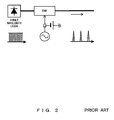
- Fig. 2 shows the basic configuration of the technique using a direct modulation pulse light source.
- a pulse light source using an electro-absorption modulator This light source is configured by a single wavelength laser light source, an EAM, an RF signal source for driving the EAM, and a direct current voltage source.
- a stable optical pulse can be accurately generated at an arbitrary repetition frequency according to the control of the RF signal source for driving the EAM.
- OSNR optical signal-to-noise ratio
- the optical transmission loss becomes 20 decibels (dB) or more because a reverse bias DC voltage is applied to the EAM by the direct current voltage source when an optical pulse is generated, although the optical transmission loss of the EAM itself is approximately 7 dB.
- Non-Patent Document 1 exists.
- the mode-locked laser pulse light source can stably generate a subpicosecond class optical pulse having a high OSNR.
- the direct modulation pulse light source its control is easy, and an optical pulse at an arbitrary and accurate repetition frequency can be generated.
- there are disadvantages such that: (1) an optical transmission loss in an optical intensity modulator is large, leading to the deterioration of the OSNR, and (2) it is difficult to generate an optical pulse having a high duty ratio since the width of the pulse is restricted by a modulation frequency.
- An object of the present invention is to provide an apparatus and method generating an optical pulse of picosecond class (having a high duty ratio) that operates accurately and stably at an arbitrary repetition frequency, has a high OSNR, and is not restricted by an RF modulation frequency.
- the optical pulse generating apparatus comprises: a light source outputting single wavelength light; and an optical pulse generating unit generating an optical pulse by generating modulation spectrum components by performing phase modulation for the light output from the light source, and by adjusting the phases of respective wavelengths of the modulation spectrum components included in the generated optical pulse.
- the optical pulse generating method comprises: outputting single wavelength light; and generating an optical pulse by generating modulation spectrum components by performing phase modulation for the light output from the light source, and by adjusting the phases of respective wavelengths of the modulation spectrum components included in the generated optical pulse.
- an optical pulse is generated by performing phase modulation, and by adjusting the phases of respective wavelengths of modulation spectrum components obtained as a result of the phase modulation, unlike the conventional techniques.
- the present invention enables the generation of an optical pulse that can be controlled with ease, accurately and stably operates at an arbitrary repetition frequency, is not restricted by the frequency of a modulation signal, and has a pulse width of picosecond class with a high duty ratio.
- phase modulation of a frequency f 0 is performed for light output from a single wavelength laser light source (frequency f).
- m is the phase modulation index
- J ⁇ is Bessel function of the first kind of an order ⁇ .
- the real part of light generated as a result of the phase modulation is represented by an equation (2).
- This equation indicates that a new wavelength component (mode of the order v) is generated for each modulation angular frequency p (namely, a frequency interval f 0 ).
- this component is referred to as a modulation spectrum component.
- the frequency f of the single wavelength laser light source is in a 200-tera hertz (THz, tera: 10 12 ) band, since a wavelength in an optical fiber communication is in a 1.5 micrometer ( ⁇ m, micro: 10 -6 ) band.
- the modulation frequency f 0 corresponds to a bit rate when an optical pulse is used as a light source for transmission of an optical communication. Namely, the modulation frequency f 0 becomes 10 GHz or 40 GHz.
- Fig. 3A and 3B are schematics explaining the first preferred embodiment according to the present invention.
- Fig. 3A shows the entire configuration.
- phase modulation is performed by a phase modulator 11 for light output from a single wavelength laser light source 10, modulation spectrum components are generated.
- the phases of wavelength components of the modulation spectrum components of the light for which the phase modulation is performed are not aligned, and are in the state of continuous light as a time waveform.
- the phases of the wavelength components of the modulation spectrum components must be aligned by a phase adjuster 13.
- an LiNbO 3 optical phase modulator (LN optical phase modulator) may be used as the device performing the phase modulation.
- This optical modulator has already been commercialized.
- a general-purpose alternate current signal oscillator (synthesizer) may be used.
- a plane blazed grating may be used.
- the principle of the phase adjuster is shown in Fig. 3B.
- the phase adjuster is configured by two plane blazed gratings.
- a first plane blazed grating 13-1 splits a light beam at a diffraction angle according to a wavelength.
- a second plane blazed grating 13-2 converts the split light beams into parallel light beams.
- the series of operations causes a difference among the paths of the wavelength components.
- a time difference of awavefrontb fromawavefront a occurs according to a wavelength, so that the wavefront is shifted. Namely, the phase adjustment according to the wavelength can be given.
- a laser light source of a wavelength 1550 nm (frequency 193. 4145 THz) is used.
- Laser light output from the single wavelength laser light source 10 is input to the optical phase modulator 11 to generate modulation spectrum components.
- sine wave phase modulation of a modulation index 5 ⁇ is performed.
- the power of the modulation signal is a value that can be sufficiently supported if an electric signal amplifier is used.
- Fig. 4 shows the configuration of the second preferred embodiment according to the present invention.
- the wavelength of a single wavelength laser is displaced to a frequency band, in which an optical pulse shift is small, with a wavelength selector 14, so that the output light becomes an optical pulse.
- Phase modulation of a modulation frequency f 0 and a modulation index 5n is performed for the light output from the single wavelength laser light source 10 of a wavelength ⁇ 0 .
- the time-bandwidth product of this optical pulse is 0.44.
- an optical pulse of Fourier Transform Limited (TL) can be generated.
- This preferred embodiment uses a phenomenon that a phase shift among the respective wavelength components of modulation spectrum components is relatively small in a frequency band where a change in frequency chirp is small as shown in Fig. 5.
Landscapes
- Physics & Mathematics (AREA)
- Nonlinear Science (AREA)
- Engineering & Computer Science (AREA)
- Ceramic Engineering (AREA)
- Signal Processing (AREA)
- Chemical & Material Sciences (AREA)
- Computer Networks & Wireless Communication (AREA)
- Crystallography & Structural Chemistry (AREA)
- Electromagnetism (AREA)
- General Physics & Mathematics (AREA)
- Optics & Photonics (AREA)
- Optical Modulation, Optical Deflection, Nonlinear Optics, Optical Demodulation, Optical Logic Elements (AREA)
- Optical Communication System (AREA)
- Semiconductor Lasers (AREA)
- Lasers (AREA)
Applications Claiming Priority (2)
| Application Number | Priority Date | Filing Date | Title |
|---|---|---|---|
| JP2003432922 | 2003-12-26 | ||
| JP2003432922A JP2005192046A (ja) | 2003-12-26 | 2003-12-26 | パルス発生装置および方法 |
Publications (2)
| Publication Number | Publication Date |
|---|---|
| EP1575194A2 true EP1575194A2 (fr) | 2005-09-14 |
| EP1575194A3 EP1575194A3 (fr) | 2005-12-21 |
Family
ID=34697701
Family Applications (1)
| Application Number | Title | Priority Date | Filing Date |
|---|---|---|---|
| EP04010084A Withdrawn EP1575194A3 (fr) | 2003-12-26 | 2004-04-28 | Générateur d'impulsions optiques |
Country Status (3)
| Country | Link |
|---|---|
| US (1) | US7088491B2 (fr) |
| EP (1) | EP1575194A3 (fr) |
| JP (1) | JP2005192046A (fr) |
Families Citing this family (3)
| Publication number | Priority date | Publication date | Assignee | Title |
|---|---|---|---|---|
| GB2434483A (en) | 2006-01-20 | 2007-07-25 | Fianium Ltd | High-Power Short Optical Pulse Source |
| GB0800936D0 (en) * | 2008-01-19 | 2008-02-27 | Fianium Ltd | A source of optical supercontinuum generation having a selectable pulse repetition frequency |
| JP2009238285A (ja) * | 2008-03-26 | 2009-10-15 | Sony Corp | 光記録方法及び光記録装置 |
Citations (6)
| Publication number | Priority date | Publication date | Assignee | Title |
|---|---|---|---|---|
| EP0676659A2 (fr) * | 1994-04-06 | 1995-10-11 | AT&T Corp. | Source bichromatique pour le génération d'impulsions à taux de répétition élevé, limitées, transformées |
| EP0854375A2 (fr) * | 1997-01-16 | 1998-07-22 | Oki Electric Industry Co., Ltd. | Générateur d'impulsion optique |
| US6072615A (en) * | 1997-06-13 | 2000-06-06 | Lucent Technologies Inc. | Phase modulator-based generation of high-quality high bit rate return-to-zero optical data streams |
| WO2002009325A1 (fr) * | 2000-07-22 | 2002-01-31 | Bookham Technology Plc | Generateur de trains d'impulsions optiques |
| US20020015212A1 (en) * | 2000-07-07 | 2002-02-07 | Masamichi Fujiwara | Multi-wavelength generating method and apparatus based on flattening of optical spectrum |
| EP1298819A2 (fr) * | 2001-09-26 | 2003-04-02 | Kabushiki Kaisha Toshiba | Dispositif et procédé pour modulation optique |
Family Cites Families (11)
| Publication number | Priority date | Publication date | Assignee | Title |
|---|---|---|---|---|
| JPH0595152A (ja) | 1991-10-01 | 1993-04-16 | Nippon Telegr & Teleph Corp <Ntt> | 半導体短光パルス発生装置および短光パルスの発生方法 |
| IT1263613B (it) | 1993-02-19 | 1996-08-27 | Pirelli Cavi Spa | Generatore laser a fibra ottica a concatenamento modale attivo |
| US6072715A (en) * | 1994-07-22 | 2000-06-06 | Texas Instruments Incorporated | Memory circuit and method of construction |
| US5473458A (en) * | 1994-12-27 | 1995-12-05 | At&T Corp. | Soliton data transmission using non-soliton transmitter |
| US5963567A (en) * | 1997-02-13 | 1999-10-05 | Lucent Technologies, Inc. | Multi-wavelength laser source |
| US7266307B2 (en) * | 2002-02-01 | 2007-09-04 | Isaac Shpantzer | Method and apparatus for pulse generation and adaptive pulse generation for optical communications |
| US7366425B2 (en) * | 2002-03-15 | 2008-04-29 | Mintera Corporation | Methods and apparatus for spectrally efficient optical modulation |
| JP3975810B2 (ja) * | 2002-04-05 | 2007-09-12 | 株式会社日立製作所 | 光片側サイドバンド送信器 |
| US6717708B2 (en) * | 2002-04-05 | 2004-04-06 | Bookham Technology, Plc | Re-circulating optical pulse generator |
| US6760142B2 (en) * | 2002-05-13 | 2004-07-06 | Lucent Technologies Inc. | Delay interferometer optical pulse generator |
| US7027669B2 (en) * | 2003-08-15 | 2006-04-11 | Lucent Technologies Inc. | Methods and apparatus for optical pulse generator with progressive phase shift |
-
2003
- 2003-12-26 JP JP2003432922A patent/JP2005192046A/ja active Pending
-
2004
- 2004-04-20 US US10/827,328 patent/US7088491B2/en not_active Expired - Fee Related
- 2004-04-28 EP EP04010084A patent/EP1575194A3/fr not_active Withdrawn
Patent Citations (6)
| Publication number | Priority date | Publication date | Assignee | Title |
|---|---|---|---|---|
| EP0676659A2 (fr) * | 1994-04-06 | 1995-10-11 | AT&T Corp. | Source bichromatique pour le génération d'impulsions à taux de répétition élevé, limitées, transformées |
| EP0854375A2 (fr) * | 1997-01-16 | 1998-07-22 | Oki Electric Industry Co., Ltd. | Générateur d'impulsion optique |
| US6072615A (en) * | 1997-06-13 | 2000-06-06 | Lucent Technologies Inc. | Phase modulator-based generation of high-quality high bit rate return-to-zero optical data streams |
| US20020015212A1 (en) * | 2000-07-07 | 2002-02-07 | Masamichi Fujiwara | Multi-wavelength generating method and apparatus based on flattening of optical spectrum |
| WO2002009325A1 (fr) * | 2000-07-22 | 2002-01-31 | Bookham Technology Plc | Generateur de trains d'impulsions optiques |
| EP1298819A2 (fr) * | 2001-09-26 | 2003-04-02 | Kabushiki Kaisha Toshiba | Dispositif et procédé pour modulation optique |
Also Published As
| Publication number | Publication date |
|---|---|
| EP1575194A3 (fr) | 2005-12-21 |
| JP2005192046A (ja) | 2005-07-14 |
| US7088491B2 (en) | 2006-08-08 |
| US20050141073A1 (en) | 2005-06-30 |
Similar Documents
| Publication | Publication Date | Title |
|---|---|---|
| US9385506B2 (en) | Wavelength tunable comb source | |
| JP5370559B2 (ja) | 光パルス発生装置及び光パルス発生方法 | |
| EP1303932B1 (fr) | Generateur de trains d'impulsions optiques | |
| US6870663B2 (en) | Wavelength tunable light source and pulse light source | |
| Huang et al. | Spectral line‐by‐line shaping for optical and microwave arbitrary waveform generations | |
| JP2009177641A (ja) | 光信号処理装置、光受信装置および光中継装置 | |
| JP2004062153A (ja) | 基準高周波信号発生方法および基準高周波信号発生装置 | |
| JP5665038B2 (ja) | 広帯域光コム発生装置 | |
| US20010053008A1 (en) | Optical pulse generating apparatus and optical signal apparatus using the same | |
| US7433564B2 (en) | Optical device for optical communication | |
| JP2002277916A (ja) | 光周波数変換装置 | |
| EP2409369B1 (fr) | Un dispositif générateur de peigne de longueurs d'onde optique | |
| JP3573334B2 (ja) | 光発生方法及び光源 | |
| EP1575194A2 (fr) | Générateur d'impulsions optiques | |
| US20050047453A1 (en) | Multi-wavelength light source apparatus | |
| JP2013025284A (ja) | 短パルス光発生装置および方法 | |
| JP2004294543A (ja) | 周期的多波長光発生装置 | |
| JP4621083B2 (ja) | マルチキャリア光源 | |
| JP2007124026A (ja) | 光クロック信号抽出方法及び光クロック信号抽出装置 | |
| JP6369946B2 (ja) | 狭線幅波長可変半導体レーザ | |
| JP3787617B2 (ja) | リングレーザを用いた四光波混合装置 | |
| JP4139831B2 (ja) | 光信号発生装置 | |
| Capmany | Microwave photonic filters | |
| Akrout et al. | Generation of 10 GHz optical pulses with very low timing jitter using one section passively mode locked quantum dash based lasers operating at 1.55 µm | |
| Shu et al. | Time-and wavelength-interleaved laser pulses: prospects and challenges in optical signal processing |
Legal Events
| Date | Code | Title | Description |
|---|---|---|---|
| PUAI | Public reference made under article 153(3) epc to a published international application that has entered the european phase |
Free format text: ORIGINAL CODE: 0009012 |
|
| AK | Designated contracting states |
Kind code of ref document: A2 Designated state(s): AT BE BG CH CY CZ DE DK EE ES FI FR GB GR HU IE IT LI LU MC NL PL PT RO SE SI SK TR |
|
| AX | Request for extension of the european patent |
Extension state: AL HR LT LV MK |
|
| PUAL | Search report despatched |
Free format text: ORIGINAL CODE: 0009013 |
|
| AK | Designated contracting states |
Kind code of ref document: A3 Designated state(s): AT BE BG CH CY CZ DE DK EE ES FI FR GB GR HU IE IT LI LU MC NL PL PT RO SE SI SK TR |
|
| AX | Request for extension of the european patent |
Extension state: AL HR LT LV MK |
|
| 17P | Request for examination filed |
Effective date: 20060620 |
|
| 17Q | First examination report despatched |
Effective date: 20060801 |
|
| AKX | Designation fees paid |
Designated state(s): DE FR GB |
|
| STAA | Information on the status of an ep patent application or granted ep patent |
Free format text: STATUS: THE APPLICATION HAS BEEN WITHDRAWN |
|
| 18W | Application withdrawn |
Effective date: 20090430 |