EP1575176A1 - Arrangement for adaptive bit recovery - Google Patents
Arrangement for adaptive bit recovery Download PDFInfo
- Publication number
- EP1575176A1 EP1575176A1 EP04005528A EP04005528A EP1575176A1 EP 1575176 A1 EP1575176 A1 EP 1575176A1 EP 04005528 A EP04005528 A EP 04005528A EP 04005528 A EP04005528 A EP 04005528A EP 1575176 A1 EP1575176 A1 EP 1575176A1
- Authority
- EP
- European Patent Office
- Prior art keywords
- arrangement according
- coefficient
- adaptive
- block
- state
- Prior art date
- Legal status (The legal status is an assumption and is not a legal conclusion. Google has not performed a legal analysis and makes no representation as to the accuracy of the status listed.)
- Withdrawn
Links
Images


Classifications
-
- G—PHYSICS
- G11—INFORMATION STORAGE
- G11B—INFORMATION STORAGE BASED ON RELATIVE MOVEMENT BETWEEN RECORD CARRIER AND TRANSDUCER
- G11B20/00—Signal processing not specific to the method of recording or reproducing; Circuits therefor
- G11B20/10—Digital recording or reproducing
- G11B20/10009—Improvement or modification of read or write signals
- G11B20/10268—Improvement or modification of read or write signals bit detection or demodulation methods
- G11B20/10287—Improvement or modification of read or write signals bit detection or demodulation methods using probabilistic methods, e.g. maximum likelihood detectors
- G11B20/10296—Improvement or modification of read or write signals bit detection or demodulation methods using probabilistic methods, e.g. maximum likelihood detectors using the Viterbi algorithm
-
- G—PHYSICS
- G11—INFORMATION STORAGE
- G11B—INFORMATION STORAGE BASED ON RELATIVE MOVEMENT BETWEEN RECORD CARRIER AND TRANSDUCER
- G11B20/00—Signal processing not specific to the method of recording or reproducing; Circuits therefor
- G11B20/10—Digital recording or reproducing
- G11B20/10009—Improvement or modification of read or write signals
- G11B20/10046—Improvement or modification of read or write signals filtering or equalising, e.g. setting the tap weights of an FIR filter
- G11B20/10055—Improvement or modification of read or write signals filtering or equalising, e.g. setting the tap weights of an FIR filter using partial response filtering when writing the signal to the medium or reading it therefrom
- G11B20/10111—Improvement or modification of read or write signals filtering or equalising, e.g. setting the tap weights of an FIR filter using partial response filtering when writing the signal to the medium or reading it therefrom partial response PR(1,2,2,1)
-
- G—PHYSICS
- G11—INFORMATION STORAGE
- G11B—INFORMATION STORAGE BASED ON RELATIVE MOVEMENT BETWEEN RECORD CARRIER AND TRANSDUCER
- G11B20/00—Signal processing not specific to the method of recording or reproducing; Circuits therefor
- G11B20/10—Digital recording or reproducing
- G11B20/10009—Improvement or modification of read or write signals
- G11B20/10268—Improvement or modification of read or write signals bit detection or demodulation methods
- G11B20/10287—Improvement or modification of read or write signals bit detection or demodulation methods using probabilistic methods, e.g. maximum likelihood detectors
-
- G—PHYSICS
- G11—INFORMATION STORAGE
- G11B—INFORMATION STORAGE BASED ON RELATIVE MOVEMENT BETWEEN RECORD CARRIER AND TRANSDUCER
- G11B20/00—Signal processing not specific to the method of recording or reproducing; Circuits therefor
- G11B20/10—Digital recording or reproducing
- G11B20/10009—Improvement or modification of read or write signals
- G11B20/10481—Improvement or modification of read or write signals optimisation methods
-
- G—PHYSICS
- G11—INFORMATION STORAGE
- G11B—INFORMATION STORAGE BASED ON RELATIVE MOVEMENT BETWEEN RECORD CARRIER AND TRANSDUCER
- G11B20/00—Signal processing not specific to the method of recording or reproducing; Circuits therefor
- G11B20/10—Digital recording or reproducing
- G11B20/12—Formatting, e.g. arrangement of data block or words on the record carriers
- G11B2020/1264—Formatting, e.g. arrangement of data block or words on the record carriers wherein the formatting concerns a specific kind of data
- G11B2020/1288—Formatting by padding empty spaces with dummy data, e.g. writing zeroes or random data when de-icing optical discs
-
- G—PHYSICS
- G11—INFORMATION STORAGE
- G11B—INFORMATION STORAGE BASED ON RELATIVE MOVEMENT BETWEEN RECORD CARRIER AND TRANSDUCER
- G11B2220/00—Record carriers by type
- G11B2220/20—Disc-shaped record carriers
- G11B2220/25—Disc-shaped record carriers characterised in that the disc is based on a specific recording technology
- G11B2220/2537—Optical discs
- G11B2220/2541—Blu-ray discs; Blue laser DVR discs
Definitions
- the present invention generally relates to an arrangement for adaptive bit recovery, and more specifically to an arrangement for adaptive bit recovery from an optical recording medium. It further relates to an apparatus for reading from and/or writing to recording media using such arrangement.
- FIG. 1 A high frequency data stream HF captured from a recording medium is sampled and quantized in an analog-to-digital converter 1, resampled to the data channel clock rate by a sample rate converter 4, and fed to a bit recovery block 11 dealing with the channel adaptation.
- the channel clock for the resampling is recovered in a clock recovery block 10, which typically includes a phase locked loop 3 preceded by an equalizer 2.
- the data for this equalizer 2 is either received directly from the analog-to-digital converter 1 or as phase information from the bit recovery block 11.
- the obtained data and the clock are transmitted to a demodulator 9, which sends the demodulated data to error correction processing (to ECC).
- the bit recovery block includes an adaptive equalizer 8 and an associated coefficient updating block 7, which uses the least mean square (LMS) algorithm and weights the output of the adaptive equalizer 8 with the recovered data after filtering by a target filter 5. Due to the increased intersymbol interference of current modulation schemes for channels of optical recording media a partial response maximum likelihood detector 6 is provided for detecting the most likely data from the incoming data stream. Since the channel modulation generally uses a run-length limited coding scheme it is common to employ a Viterbi decoder 6.
- LMS least mean square
- an adaptive Viterbi detector 14 As shown in Fig. 2.
- the target values against which the likelihood of the possible data bit is measured are updated by a target value updating block 17. This is realized by comparing a best case value, i.e. the most likely value, with the data fed into the adaptive Viterbi decoder 15.
- a slicer 12 is provided for roughly eliminating DC components, which are not caused by the modulation but by data coupling. This is the digital counterpart of a decoupling capacitor trimmed for the lowest frequencies. The higher order DC component caused by the modulation changes on run-length time frames and is tackled in the equalizer 8.
- a state detector 16 follows the Trellis diagram of the Viterbi decoder 15 by monitoring the bit combinations.
- the Trellis diagram will be explained further below with reference to Fig. 9.
- the subsequently detected bits '++-' i.e. bit order '1 1 0' or state '4'
- the transition may be to states '4' and '5'. If an invalid transition is detected in the target update block 17 this target is not updated with the value of the corresponding input sample, which should actually give a closer match to the correct signal.
- the auxiliary detector 20 includes a pre-equalizer 21, a data pre-slicer 22, a non-linear equalizer 23, and a bit detector 24.
- This auxiliary detector 20 basically slices the bit information out of the center of the resampled hf data.
- the detector 20 has certain limitations considering run-length dependent parasitic DC-components, and tends to misdetect the shorter run-length data bits.
- the auxiliary detector 20 outperforms the Viterbi detector 14 when dealing with corrupted data regions on a recording medium and does not have the detection latency immanent to the filter length and path memory depth used in the Viterbi bit detection path 14.
- An event logic 25 as indicated in Fig. 3 decodes the data sample transition as above zero, zero or below zero and passes this information to the clock recovery block 10 (not shown here) together with the corresponding phase value.
- VLSI very large scale integrated circuits
- an arrangement for adaptive bit recovery including an adaptive equalizer and an adaptive partial response maximum likelihood detector, which further includes enhanced control measures for the adaptive equalizer and/or the adaptive partial response maximum likelihood detector.
- the enhanced control measures include an overflow control block for the adaptive equalizer for monitoring at least one of the adaptation coefficients.
- the equalizer is realized as a simplified finite impulse response (FIR) Volterra filter
- the overflow control block advantageously monitors the Volterra coefficient. Basically this coefficient is treated as a measure for the signal asymmetry. However, if the jitter of the incoming data is too high, this coefficient might run out of the intended data range.
- the overflow control is expanded to all coefficients.
- a scaling block applies a scaling to the coefficient paths based on an output signal of the overflow control block.
- the arrangement further includes means for obtaining phase information by comparing the highest absolute coefficient value with its coefficient number.
- a constant group delay caused by the filtering always gives the maximum coefficient value at the same position.
- the middle tap has the highest value.
- the obtained information is passed to a host control as a phase warning, for example as a flag indicating that the phase is on or off the optimum, or as a position identifier indicating the coefficient having the highest value.
- the enhanced control measures include a control logic for an adaptation constant (MU) for a coefficient update weight.
- the coefficient update weight is favorably larger during the beginning of the adaptation process than during normal operation.
- the operation of the control logic is simplified and concentrates on only a few coefficients.
- the coefficients are filtered, e.g. by a mean time average filtering, and compared for finding the highest value. This might change during the adaptation process, therefore a locking to a single coefficient is necessary. This locking might be unlocked either by the host control or by a lock time counter.
- the speed of adaptation is monitored by analyzing the gradient of the coefficient transitions. Since noise may cause larger changes of the slope of the coefficient transitions an effective pre-filtering is advantageously performed. In dependence on the value of the detected gradient a scaling of the adaptation constant is performed. Another information obtained by the monitoring is the state of adaptation during run-in. A small value of the gradient implies that the coefficient values do not change much and, therefore, implies an almost stable adaptation.
- the enhanced control measures include a state violation checker for monitoring the allowed states and indicating state violations, and a noise detector for detecting larger deviations of the target values.
- the recovered data are generally mapped to the respective Trellis state with the aid of a look-up table.
- the state violation checker monitors the allowed state. As soon as an invalid entry of the look-up table appears an error indication is generated and the target value update is disabled.
- the noise detection block monitors the target values to detect larger deviations. This monitoring is favorably simplified to the middle value.
- the middle target value of the selected partial response estimate is filtered, mainly to remove low frequency components like a spurious DC offset, and compared with given noise levels noise. Even if the adaptation has actually settled, the target value changes exhibit a large activity.
- the noise level is preferably transmitted to the host control as a noise warning and is used for controlling a scaling of the target value update to reduce the impact of input sample changes.
- the enhanced control measures include a path memory and survivor control block for storing path decisions for each state and the most likely state.
- the path memory and survivor control block favorably includes an output checker for finding invalid bit transitions. These can occur, for example, due to a path switching when the noise level is too high to calculate accurate probabilities for the most likely path.
- the path decisions for each state and the most likely state are stored in the path memory and survivor control block, which includes a plurality of path memory cells. Each cell includes a memory for the selected path id, a path mapper and a 'next state'-state machine.
- the path mapper is basically a look-up table for all possible paths allowed by the relevant Trellis diagram.
- the 'next state'-state machine compares the incoming path id map with the offered minimum state to calculate the next state representing the next most likely minimum state. By building up a chain of path memory cells these operations are unrolled over the history of incoming data bit values.
- the output state of the last pm cell is translated into a most likely bit along this most likely Trellis path.
- At the output of the pm cells always valid states are found.
- the path along the Trellis diagram might change due to noise or data corruption, invalid bit sequences may occur. Therefore, the output checker stores,a certain number of bits, depending on the minimum(maximum) run-length of the selected channel modulation, and flags the current bit as violation or as clean. A demodulator is then able to determine a proper bit replacement according to its demodulation scheme.
- error information is provided to further processing units for supporting data processing.
- error locations can be indicated to the demodulation block or an error correction control.
- an arrangement for adaptive bit recovery according to the invention is used in an apparatus for reading from and/or writing to recording media.
- the circuit 11 includes a coarse asymmetry compensation block 26 and emits so called erasure flags era_eq, era_vit for indicating error locations to following processing stages like the demodulation block 9 or error correction control.
- the adaptive equalizer 13 is divided into the blocks equalizer 8, target filter 5, and least mean square (LMS) update 7, as depicted in Fig. 2.
- the equalizer 8 is realized as a simplified finite impulse response (FIR) Volterra filter following the basic formula in which h 0 corresponds to the DC component, the second term to the linear FIR filter component, and the third term to a quadratic Volterra component. Higher order terms are neglected in this example.
- FIR finite impulse response
- This operation is divided into an X delay process performed by the X delay unit 83 and an add and multiply operation performed by the MAC unit 84.
- the X-vector element x 3 represents the hf input data at the group delay of the linear filter 81 and is squared and multiplied with the Volterra coefficient c_vol. It can be shown that the provision of an equalizer including such non-linear element improves the performance with regard to channel adaptation in the case of distortion by non-linear effects such as a run-length dependent DC offset caused by domain bloom, i.e. asymmetry.
- the filtered feedback of the recovered data ref_data_in is compared with the equalizer output eq_out, weighted with an adaptation constant MU against the equalizer input x_del, and integrated in a set of accumulators 72.
- some debasement is accepted by assuming a symmetrical filter. This in return allows to simplify the calculations.
- averagers 71 are provided.
- the feedback filter (target filter) 5 is a linear FIR filter including a delay unit 51 and a MAC unit 52 and following a partial response estimate for the considered data channel.
- this filter 5 is defined by stating the (symmetrical) filter coefficients PR(abba). For example, for DVD (digital versatile disk) PR(1111) and for BD (Blu-ray disk) PR(1221) are common.
- the equalizer output eq_out and the X-vector are delayed by the X delay unit 83 and an EQ delay unit 85, respectively.
- an overflow control block 86 for the filter coefficients and a MU control logic 74 are provided, which shall be described in the following.
- the host control delays the start of adaptation to prevent lock-ups or confusion.
- the adaptation of the Viterbi decoder 15 is added.
- a loadable initialization counter 73 within the adaptive equalizer 13 simplifies the start/restart process. As an example, in Fig. 5 this initialization counter 73 is included in the LMS update block 7 of the adaptive equalizer 13.
- the filter coefficients tend to change rapidly in the beginning of the adaptive process.
- the adaptivity might fail or might match to wrong phases.
- the middle tap of the linear filter will have the highest absolute value. All deviations from this optimum give indications of signal quality and therefore the possible quality of bit recovery process.
- an overflow control block 86 within the equalizer 8 monitors the Volterra coefficient (c_vol). Basically this coefficient is treated as a measure for the signal asymmetry. However, if the jitter of the incoming data is too high, this coefficient might run out of the intended data range.
- c_vol Volterra coefficient
- threshold value of 120 is only exemplary and has to be chosen in accordance with the actual implementation of the complete arrangement.
- the scaling is considered in the filter process, giving this coefficient a larger impact.
- the overflow control 86 is expanded to all coefficients, which is schematically illustrated in Fig. 6.
- the MAC unit 84 which includes the summations and multiplications for the Volterra coefficients, passes the coefficient values to a range checker 87.
- a scaling block 89 applies a scaling to the respective coefficient path in the MAC unit 84.
- the selection can, for example, be determined by register settings or based on the detected maximum values of the coefficients. In general the middle coefficient should have the largest value. If this is not the case a phase error is introduced and other coefficients have to be scaled.
- phase information is favorably obtained by comparing the highest absolute coefficient value with its coefficient number.
- a constant group delay caused by the filtering always gives the maximum coefficient value at the same position.
- the middle tap has the highest value.
- the obtained information is passed to the host control as a phase warning either as a flag (e.g. PHASE OFF/ON OPTIMUM) or as a position identifier (COEFF0, COEFF1, COEFF2, COEFF3,).
- the MU logic 74 in the LMS update block 7 is provided for the coefficient update weight, which is favorably larger during the beginning of the adaptation process than during normal operation.
- a possible implementation of the MU logic 74 is depicted in Fig. 7. The operation is simplified and concentrates on only a few coefficients. Typically the middle tap of the linear filter has the highest coefficient value. In the symmetric seven tap example this is the coefficient c3.
- a noise free adaptation has the odd numbered coefficient as the next highest value, but due to the possibility of phase distortion it might also be c2.
- the coefficient locations in the filter and LMS operation are indicated above in equation (2).
- the coefficients are filtered, e.g. by a mean time average filtering, and compared by a comparing block 75 to find the highest value. Since this might change during the adaptation process, a locking to a single coefficient is required, which can be unlocked either by the host control or by a lock time counter.
- a MU scaling is performed by a set level block 77:
- the Viterbi decoder 15 includes means comparable to the overflow control 86 or the MU logic 74. Details are discussed in the following.
- Fig. 8 depicts an outline of the adaptive Viterbi decoder 15.
- a Viterbi decoder is built up on the assumption that only certain transitions of bit levels are possible due to the given run-length limitation of the data channel modulation. These bit levels are compared with a partial response estimate of this channel. This partial response estimate does not represent the perfect representation of the channel, but allows to add enough noise margin to distinguish between bit value transitions even when dealing with data streams affected by a large amount of intersymbol interference (ISI). Due to their different modulations different partial response estimates are used for DVD and BD.
- ISI intersymbol interference
- the Viterbi decoder 15 in Fig. 8 realizes a soft decision scheme by comparing the squared difference (Euclidian distance) obtained by a distance calculation block 150 with the so-called target values of the selected partial response polynomial.
- an interface 151 to the host controller allows an initialization upon start-up.
- An add-compare-select (ACS) unit 152 adds up the squared differences and compares the results along the possible transition paths.
- a diagram of such a scheme which is known as Trellis diagram, is shown in Fig. 9 at the example of a BD Trellis diagram with run-length limit '2'.
- Valid states are indicated as sequences of '+' and '-' representing '0' and '1' in a bit stream. All allowed transitions to other states for the next bit transmission are along the indicated lines in dependence on the type of transition.
- the ACS unit 152 maintains, therefore, a set of states and state value differences to the current incoming data value.
- the minimum distance to the data value gives the most likely transition.
- the state with the smallest value represents the survivor path and is stored in a path memory and survivor control unit 153. Since the optimum distance is not found during the first bit transmissions a set of states and paths is kept.
- a typical value for the depth of storage is '15'.
- Trellis diagram consider for an overall value range (+128,...,-128) a data value sequence '120,120,120' resulting in the state '+++' (or state ID 5).
- a following data value of '100' causes a transition to either state 4 or state 5 (Path ID 5 or 6).
- the partial response for BD is selected as PR(1221), i.e. the coefficients for the respective partial response value are 1, 2, 2 and 1. Feeding a sequence of '1's and '0's to the partial response filter can only result in certain output values.
- '+1' as bit '1' and '-1' as bit '0' the possible target values are given in Fig. 9 as '-6, -4, -2, 0, +2, +4, +6'.
- Target Value not scaled -6 -4 -2 0 +2 +4 +6.
- the value of the next state is given by the minimum path value added to the current state value. For state '5', therefore, two paths are possible and so on. The state with the smallest value is the most likely next state. Therefore, a decoder just needs to know this state to distinguish the most likely bit.
- updates for the target values are calculated. These updates are derived from the partial response estimate based on the data detection history and the incoming equalized data stream eq_out delayed by a delay element 156.
- a state violation checker 162 In order to improve the performance of the arrangement for bit recovery during processing of erroneous data patterns a state violation checker 162, a noise detector 155, and a bit decode control are provided. These blocks are discussed in detail in the following.
- Fig. 10 shows a possible implementation of the adaptive target value updating block 154.
- the recovered data (reference data) are mapped to the respective Trellis state with the aid of a look-up table 160.
- the state violation checker 162 monitors the allowed state. As soon as an invalid entry of the look-up table 160 comes up an error indication is generated (state violated) and the target value update is disabled.
- the noise detection block 155 monitors the target values to detect larger deviations. In the figure this monitoring is simplified to the middle value TV3*. For this purpose it has to be ensured that the main adaptation process has already ended or that the gradient of adaptation is known. If it is assumed that the slice level is settled (cf. slicer 12 in Fig. 4) and the equalizer 13 has settled adaptation ('adaptation done' in Fig. 7) according to a preferable implementation a noise level check by a noise level checker 155 is initiated as indicated in Fig. 10.
- the middle target value TV3* of the selected partial response estimate is filtered, mainly to remove low frequency components like a spurious DC offset, and compared with given noise levels noise lvl.
- a typical noisy case is shown in Fig. 11. Depicted are the changes of the target values against the number of input data samples. As can be seen, though the adaptation has actually settled, the target value changes exhibit a large activity.
- the noise level is preferably transmitted to the host control as a noise warning and is used to control a scaling of the target value update by a scaling block 163 to reduce the impact of input sample changes. This is, for example, achieved by reducing the integration constant of the integration array 161.
- the path memory and survivor control block 153 includes an output checker 175 for finding invalid bit transitions due to a path switching when the noise level is too high to calculate accurate probabilities for the most likely path.
- the soft decision of the Viterbi decoder 15 stores the path decisions for each state and the most likely state in the path memory and survivor control block 153.
- the first stage is shown as 'pm cell 1' 170 and includes a memory 171 for the selected path id, a path mapper 172 and a 'next state'-state machine 173.
- the path mapper 172 is basically a look-up table for all possible paths shown in the Trellis diagram of Fig. 9. Some state transition paths do not need an extra path ID and consequently additional memory 171, since only a single option is possible. Such a case is, for example, the transition path from state '4' to state '3'.
- the 'next state'-state machine 173 compares the incoming path id map with the offered minimum state to calculate the next state representing the next most likely minimum state. By building up a chain of path memory cells these operations are unrolled over the history of incoming data bit values. The output state of the last pm cell is translated into a most likely bit along this most likely Trellis path. In this way a state '4' would directly translate into a '-1' (i.e. '0') and a state '5' into a '+1' (i.e. '1').
- the output checker 175 stores three(nine) bits, depending on the minimum(maximum) run-length of the selected channel modulation, and flags the current bit being fed to the demodulator 9 as violation (erasure flag set) or as clean (erasure flag cleared). The demodulator 9 is then able to determine a proper bit replacement according to its demodulation scheme.
Abstract
The present invention relates to an arrangement for adaptive
bit recovery, and to an apparatus for reading from and/or
writing to recording media using such arrangement.
According to the invention, an arrangement for adaptive bit
recovery including an adaptive equalizer (13) and an adaptive
partial response maximum likelihood detector (14) further
includes enhanced control measures for the adaptive equalizer
(13) and/or the adaptive partial response maximum likelihood
detector (14).
Description
The present invention generally relates to an arrangement for
adaptive bit recovery, and more specifically to an arrangement
for adaptive bit recovery from an optical recording medium. It
further relates to an apparatus for reading from and/or writing
to recording media using such arrangement.
Recently techniques have been developed for a channel adaptive
recovery of data from optical recording media. However, due to
the multitude of possible media types, e.g. Compact Disk,
Digital Versatile Disk, Blu-ray Disk, and many other types, and
the fact that some recording media types are not protected by a
housing, a stronger monitoring of the adaptive processes is
required. For this purpose several solutions were proposed to
implement a reliable data retrieval processing. One solution is
depicted in Fig. 1. A high frequency data stream HF captured
from a recording medium is sampled and quantized in an analog-to-digital
converter 1, resampled to the data channel clock
rate by a sample rate converter 4, and fed to a bit recovery
block 11 dealing with the channel adaptation. The channel clock
for the resampling is recovered in a clock recovery block 10,
which typically includes a phase locked loop 3 preceded by an
equalizer 2. The data for this equalizer 2 is either received
directly from the analog-to-digital converter 1 or as phase
information from the bit recovery block 11. The obtained data
and the clock are transmitted to a demodulator 9, which sends
the demodulated data to error correction processing (to ECC).
The bit recovery block includes an adaptive equalizer 8 and an
associated coefficient updating block 7, which uses the least
mean square (LMS) algorithm and weights the output of the
adaptive equalizer 8 with the recovered data after filtering by
a target filter 5. Due to the increased intersymbol
interference of current modulation schemes for channels of
optical recording media a partial response maximum likelihood
detector 6 is provided for detecting the most likely data from
the incoming data stream. Since the channel modulation
generally uses a run-length limited coding scheme it is common
to employ a Viterbi decoder 6.
More recently it has been proposed to provide an adaptive
Viterbi detector 14 as shown in Fig. 2. In this case, while
monitoring the output of the Viterbi detector 15, i.e. the
recovered data bits, the target values against which the
likelihood of the possible data bit is measured are updated by
a target value updating block 17. This is realized by comparing
a best case value, i.e. the most likely value, with the data
fed into the adaptive Viterbi decoder 15. A slicer 12 is
provided for roughly eliminating DC components, which are not
caused by the modulation but by data coupling. This is the
digital counterpart of a decoupling capacitor trimmed for the
lowest frequencies. The higher order DC component caused by the
modulation changes on run-length time frames and is tackled in
the equalizer 8. A state detector 16 follows the Trellis
diagram of the Viterbi decoder 15 by monitoring the bit
combinations. The Trellis diagram will be explained further
below with reference to Fig. 9. For example, the subsequently
detected bits '++-' (i.e. bit order '1 1 0' or state '4') only
allow a transition to a following state '3'. From state '2' the
transition may be to states '4' and '5'. If an invalid
transition is detected in the target update block 17 this
target is not updated with the value of the corresponding input
sample, which should actually give a closer match to the
correct signal.
However, adaptive processes tend to become unstable and
counteractive under certain circumstances like initialization
or when dealing with errors in the data stream caused by
scratches or fingerprints. Therefore, it has been proposed to
introduce an auxiliary detector 20 to improve the adaptation
performance of the bit recovery block 11 under such conditions
and to meet high speed data detection requirements. A scheme of
such an arrangement is shown in Fig. 3. The auxiliary detector
20 includes a pre-equalizer 21, a data pre-slicer 22, a non-linear
equalizer 23, and a bit detector 24. This auxiliary
detector 20 basically slices the bit information out of the
center of the resampled hf data. The detector 20 has certain
limitations considering run-length dependent parasitic DC-components,
and tends to misdetect the shorter run-length data
bits. Nevertheless, the auxiliary detector 20 outperforms the
Viterbi detector 14 when dealing with corrupted data regions on
a recording medium and does not have the detection latency
immanent to the filter length and path memory depth used in the
Viterbi bit detection path 14. An event logic 25 as indicated
in Fig. 3 decodes the data sample transition as above zero,
zero or below zero and passes this information to the clock
recovery block 10 (not shown here) together with the
corresponding phase value.
When dealing with several types of recording media and channels
(e.g. DVD+RW, DVD-RW etc.) a high degree of flexibility is
required for the adaptation processes. Some flexibility can
still only be provided by a system reconfiguration initiated by
a host control, but some flexibility is already within the
scope of hardware implementation, due to the increased
integration level of very large scale integrated circuits
(VLSI).
It is an object of the present invention to provide an improved
arrangement for adaptive bit recovery allowing a reliable bit
detection exceeding the performance of common data detection
processors.
According to the invention, this object is achieved by an
arrangement for adaptive bit recovery including an adaptive
equalizer and an adaptive partial response maximum likelihood
detector, which further includes enhanced control measures for
the adaptive equalizer and/or the adaptive partial response
maximum likelihood detector. Favorably the enhanced control
measures include an overflow control block for the adaptive
equalizer for monitoring at least one of the adaptation
coefficients. If the equalizer is realized as a simplified
finite impulse response (FIR) Volterra filter, the overflow
control block advantageously monitors the Volterra coefficient.
Basically this coefficient is treated as a measure for the
signal asymmetry. However, if the jitter of the incoming data
is too high, this coefficient might run out of the intended
data range. In a more general approach the overflow control is
expanded to all coefficients. In the case of overflow a scaling
block applies a scaling to the coefficient paths based on an
output signal of the overflow control block.
Favorably, the arrangement further includes means for obtaining
phase information by comparing the highest absolute coefficient
value with its coefficient number. A constant group delay
caused by the filtering always gives the maximum coefficient
value at the same position. For an optimum filter coefficient
set the middle tap has the highest value. The obtained
information is passed to a host control as a phase warning, for
example as a flag indicating that the phase is on or off the
optimum, or as a position identifier indicating the coefficient
having the highest value.
According to a further aspect of the invention, the enhanced
control measures include a control logic for an adaptation
constant (MU) for a coefficient update weight. The coefficient
update weight is favorably larger during the beginning of the
adaptation process than during normal operation. Favorably the
operation of the control logic is simplified and concentrates
on only a few coefficients. The coefficients are filtered, e.g.
by a mean time average filtering, and compared for finding the
highest value. This might change during the adaptation process,
therefore a locking to a single coefficient is necessary. This
locking might be unlocked either by the host control or by a
lock time counter. The speed of adaptation is monitored by
analyzing the gradient of the coefficient transitions. Since
noise may cause larger changes of the slope of the coefficient
transitions an effective pre-filtering is advantageously
performed. In dependence on the value of the detected gradient
a scaling of the adaptation constant is performed. Another
information obtained by the monitoring is the state of
adaptation during run-in. A small value of the gradient implies
that the coefficient values do not change much and, therefore,
implies an almost stable adaptation.
According to still a further aspect of the invention, the
enhanced control measures include a state violation checker for
monitoring the allowed states and indicating state violations,
and a noise detector for detecting larger deviations of the
target values. The recovered data are generally mapped to the
respective Trellis state with the aid of a look-up table. The
state violation checker monitors the allowed state. As soon as
an invalid entry of the look-up table appears an error
indication is generated and the target value update is
disabled. In addition the noise detection block monitors the
target values to detect larger deviations. This monitoring is
favorably simplified to the middle value. For the noise level
check the middle target value of the selected partial response
estimate is filtered, mainly to remove low frequency components
like a spurious DC offset, and compared with given noise levels
noise. Even if the adaptation has actually settled, the target
value changes exhibit a large activity. The noise level is
preferably transmitted to the host control as a noise warning
and is used for controlling a scaling of the target value
update to reduce the impact of input sample changes.
Advantageously, the enhanced control measures include a path
memory and survivor control block for storing path decisions
for each state and the most likely state. The path memory and
survivor control block favorably includes an output checker for
finding invalid bit transitions. These can occur, for example,
due to a path switching when the noise level is too high to
calculate accurate probabilities for the most likely path. The
path decisions for each state and the most likely state are
stored in the path memory and survivor control block, which
includes a plurality of path memory cells. Each cell includes a
memory for the selected path id, a path mapper and a 'next
state'-state machine. The path mapper is basically a look-up
table for all possible paths allowed by the relevant Trellis
diagram. The 'next state'-state machine compares the incoming
path id map with the offered minimum state to calculate the
next state representing the next most likely minimum state. By
building up a chain of path memory cells these operations are
unrolled over the history of incoming data bit values. The
output state of the last pm cell is translated into a most
likely bit along this most likely Trellis path. At the output
of the pm cells always valid states are found. The path along
the Trellis diagram might change due to noise or data
corruption, invalid bit sequences may occur. Therefore, the
output checker stores,a certain number of bits, depending on
the minimum(maximum) run-length of the selected channel
modulation, and flags the current bit as violation or as clean.
A demodulator is then able to determine a proper bit
replacement according to its demodulation scheme.
Favorably the generated error information is provided to
further processing units for supporting data processing. For
example, error locations can be indicated to the demodulation
block or an error correction control.
Favorably, an arrangement for adaptive bit recovery according
to the invention is used in an apparatus for reading from
and/or writing to recording media.
For a better understanding of the invention, an exemplary
embodiment is specified in the following description with
reference to the figures. It is understood that the invention
is not limited to this exemplary embodiment and that specified
features can also expediently be combined and/or modified
without departing from the scope of the present invention. In
the figures:
- Fig. 1
- shows a known arrangement for adaptive bit recovery;
- Fig. 2
- schematically depicts an improved adaptive bit recovery block including an adaptive Viterbi decoder;
- Fig. 3
- shows a bit recovery block including a main and an auxiliary detector;
- Fig. 4
- depicts an exemplary embodiment of an arrangement for bit recovery according to the invention;
- Fig. 5
- shows a more detailed scheme of an adaptive equalizer;
- Fig. 6
- illustrates the expansion of an overflow control to all filter coefficients;
- Fig. 7
- shows an implementation of a MU logic;
- Fig. 8
- depicts an outline of an adaptive Viterbi decoder;
- Fig. 9
- illustrates a Trellis diagram for PR(1221) and a run-length limit of '2';
- Fig. 10
- shows an implementation of an adaptive target value updating block;
- Fig. 11
- depicts the changes of the target values against the input data samples; and
- Fig. 12
- shows an implementation of a math memory and survivor control block.
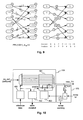
An exemplary embodiment of an arrangement according to the
invention is depicted in Fig. 4. The circuit 11 includes a
coarse asymmetry compensation block 26 and emits so called
erasure flags era_eq, era_vit for indicating error locations to
following processing stages like the demodulation block 9 or
error correction control.
A more detailed scheme of the adaptive equalizer 13 is shown in
Fig. 5. The adaptive equalizer 13 is divided into the blocks
equalizer 8, target filter 5, and least mean square (LMS)
update 7, as depicted in Fig. 2. The equalizer 8 is realized as
a simplified finite impulse response (FIR) Volterra filter
following the basic formula
 in which h 0 corresponds to the DC component, the second term to
the linear FIR filter component, and the third term to a
quadratic Volterra component. Higher order terms are neglected
in this example. According to the implementation scheme this
formula is simplified and the
in which h 0 corresponds to the DC component, the second term to
the linear FIR filter component, and the third term to a
quadratic Volterra component. Higher order terms are neglected
in this example. According to the implementation scheme this
formula is simplified and the equalizer 8 is divided into a
linear FIR portion 81 including an X delay unit 83 and a MAC
(multiply-accumulate) unit 84, and a simplified Volterra
portion 82 with c_dc = h 0 and c_vol representing a quadratic
filter coefficient h 2 (m 1 ,m 2 ). For this coefficient only the
multiplication with the squared middle element of the filtered
X-vector is required.
An example of a typical implementation shall be explained in
the following. The linear FIR filter 81 includes a seven tap
(N = 7) filter with a symmetrical coefficient set. Therefore
the filtering at time sample n=0 is:
N = 7
y = eq_out = c 0 · x 0 + c 1 · x 1 + c 2 · x 2 + c 3 · x 3 + c 2 · x 4 + c 1 · x 5 + c 0 · x 6
This operation is divided into an X delay process performed by
the X delay unit 83 and an add and multiply operation performed
by the MAC unit 84. The X-vector element x 3 represents the hf
input data at the group delay of the linear filter 81 and is
squared and multiplied with the Volterra coefficient c_vol. It
can be shown that the provision of an equalizer including such
non-linear element improves the performance with regard to
channel adaptation in the case of distortion by non-linear
effects such as a run-length dependent DC offset caused by
domain bloom, i.e. asymmetry.
For adapting the equalizer coefficients to the data channel a
new set of coefficients is calculated in the LMS update block
7. Again the symmetric coefficient set allows a simplified
implementation of the general LMS formula:
C new = C old + µ · ∑ (tfout - eqout *)·x
Basically the filtered feedback of the recovered data
ref_data_in is compared with the equalizer output eq_out,
weighted with an adaptation constant MU against the equalizer
input x_del, and integrated in a set of accumulators 72. In
order to reduce the number of filter coefficients some
debasement is accepted by assuming a symmetrical filter. This
in return allows to simplify the calculations. For this purpose
averagers 71 are provided. The feedback filter (target filter)
5 is a linear FIR filter including a delay unit 51 and a MAC
unit 52 and following a partial response estimate for the
considered data channel. Usually this filter 5 is defined by
stating the (symmetrical) filter coefficients PR(abba). For
example, for DVD (digital versatile disk) PR(1111) and for BD
(Blu-ray disk) PR(1221) are common.
In order to match the coefficients the equalizer output eq_out
and the X-vector, i.e. the equalizer input, are delayed by the
X delay unit 83 and an EQ delay unit 85, respectively.
To improve and support the adaptation and error handling
behavior a run-in delay, an overflow control block 86 for the
filter coefficients and a MU control logic 74 are provided,
which shall be described in the following.
During run-in, i.e. after the start of data retrieval following
a jump, the host control delays the start of adaptation to
prevent lock-ups or confusion. Typically, after a rough channel
estimation by the adaptive equalizer 13 the adaptation of the
Viterbi decoder 15 is added. A loadable initialization counter
73 within the adaptive equalizer 13 simplifies the
start/restart process. As an example, in Fig. 5 this
initialization counter 73 is included in the LMS update block 7
of the adaptive equalizer 13.
The filter coefficients tend to change rapidly in the beginning
of the adaptive process. Depending on the signal quality of the
incoming hf data (Jitter, additive Noise etc.) the adaptivity
might fail or might match to wrong phases. Basically the middle
tap of the linear filter will have the highest absolute value.
All deviations from this optimum give indications of signal
quality and therefore the possible quality of bit recovery
process.
In Fig. 5 an overflow control block 86 within the equalizer 8
monitors the Volterra coefficient (c_vol). Basically this
coefficient is treated as a measure for the signal asymmetry.
However, if the jitter of the incoming data is too high, this
coefficient might run out of the intended data range. A typical
implementation would be:

Of course, the threshold value of 120 is only exemplary and has
to be chosen in accordance with the actual implementation of
the complete arrangement. The scaling is considered in the
filter process, giving this coefficient a larger impact.
In a more general approach the overflow control 86 is expanded
to all coefficients, which is schematically illustrated in
Fig. 6. The MAC unit 84, which includes the summations and
multiplications for the Volterra coefficients, passes the
coefficient values to a range checker 87. Depending on the
overflow and the importance of a coefficient, which is selected
by the range checker 87 via a selector 88, a scaling block 89
applies a scaling to the respective coefficient path in the MAC
unit 84. The selection can, for example, be determined by
register settings or based on the detected maximum values of
the coefficients. In general the middle coefficient should have
the largest value. If this is not the case a phase error is
introduced and other coefficients have to be scaled. In Fig. 5
the scaling is indicated by the multiplier following the
overflow control 86. In addition, phase information is
favorably obtained by comparing the highest absolute
coefficient value with its coefficient number. A constant group
delay caused by the filtering always gives the maximum
coefficient value at the same position. For an optimum filter
coefficient set the middle tap has the highest value. The
obtained information is passed to the host control as a phase
warning either as a flag (e.g. PHASE OFF/ON OPTIMUM) or as a
position identifier (COEFF0, COEFF1, COEFF2, COEFF3,...).
The MU logic 74 in the LMS update block 7 is provided for the
coefficient update weight, which is favorably larger during the
beginning of the adaptation process than during normal
operation. A possible implementation of the MU logic 74 is
depicted in Fig. 7. The operation is simplified and
concentrates on only a few coefficients. Typically the middle
tap of the linear filter has the highest coefficient value. In
the symmetric seven tap example this is the coefficient c3. A
noise free adaptation has the odd numbered coefficient as the
next highest value, but due to the possibility of phase
distortion it might also be c2. The coefficient locations in
the filter and LMS operation are indicated above in equation
(2).
The coefficients are filtered, e.g. by a mean time average
filtering, and compared by a comparing block 75 to find the
highest value. Since this might change during the adaptation
process, a locking to a single coefficient is required, which
can be unlocked either by the host control or by a lock time
counter.
By analyzing the gradient of the coefficient transitions the
speed of adaptation is monitored. Since noise may cause larger
changes of the slope of the coefficient transitions an
effective pre-filtering is advantageously performed. A simple
implementation of a gradient analyzing block 76 for finding the
gradient includes a delay line and a subtraction:
grad=coeff_in-coeff_in_delayed
In dependence on the value of the detected gradient a MU
scaling is performed by a set level block 77:

given that the LMS weight is done by a division by a large
number and therefore actually represents 1/m. Of course, the
above values are only exemplary values. Bit shifts such as
multiplications result in MU values around '8' depending on the
bitwidth used in the LMS update operation.
Another information obtained by the monitoring is the state of
adaptation during run-in. A small value of the gradient implies
that the coefficient values do not change much and, therefore,
implies an almost stable adaptation.
As a second adaptation process in the arrangement for bit
recovery discussed here, the Viterbi decoder 15 includes means
comparable to the overflow control 86 or the MU logic 74.
Details are discussed in the following.
Fig. 8 depicts an outline of the adaptive Viterbi decoder 15. A
Viterbi decoder is built up on the assumption that only certain
transitions of bit levels are possible due to the given run-length
limitation of the data channel modulation. These bit
levels are compared with a partial response estimate of this
channel. This partial response estimate does not represent the
perfect representation of the channel, but allows to add enough
noise margin to distinguish between bit value transitions even
when dealing with data streams affected by a large amount of
intersymbol interference (ISI). Due to their different
modulations different partial response estimates are used for
DVD and BD.
The Viterbi decoder 15 in Fig. 8 realizes a soft decision
scheme by comparing the squared difference (Euclidian distance)
obtained by a distance calculation block 150 with the so-called
target values of the selected partial response polynomial. In
order to be able to reconfigure the Viterbi decoder 15 to the
corresponding data channel an interface 151 to the host
controller allows an initialization upon start-up.
An add-compare-select (ACS) unit 152 adds up the squared
differences and compares the results along the possible
transition paths. A diagram of such a scheme, which is known as
Trellis diagram, is shown in Fig. 9 at the example of a BD
Trellis diagram with run-length limit '2'. Valid states are
indicated as sequences of '+' and '-' representing '0' and '1'
in a bit stream. All allowed transitions to other states for
the next bit transmission are along the indicated lines in
dependence on the type of transition.
The ACS unit 152 maintains, therefore, a set of states and
state value differences to the current incoming data value. The
minimum distance to the data value gives the most likely
transition. The state with the smallest value represents the
survivor path and is stored in a path memory and survivor
control unit 153. Since the optimum distance is not found
during the first bit transmissions a set of states and paths is
kept. A typical value for the depth of storage is '15'.
As an example of a Trellis diagram consider for an overall
value range (+128,...,-128) a data value sequence '120,120,120'
resulting in the state '+++' (or state ID 5). A following data
value of '100' causes a transition to either state 4 or state 5
(Path ID 5 or 6). The partial response for BD is selected as
PR(1221), i.e. the coefficients for the respective partial
response value are 1, 2, 2 and 1. Feeding a sequence of '1's
and '0's to the partial response filter can only result in
certain output values. In the case of '+1' as bit '1' and '-1'
as bit '0' the possible target values are given in Fig. 9 as '-6,
-4, -2, 0, +2, +4, +6'.
The most likely next state for this transition is, therefore,
state '4'.
PR(1221), data input 120,120,120,100 with the assumption that
the first three bits are already detected and the provision to
scale the partial response sequence output to a range from +128
to -128.
path 5: 120×(102)+120×(102)+120×(102)+100×(68)
path 6: 120×(102)+120×(102)+120×(102)+100×(102)
| Target Value: | |||||||
| not scaled | -6 | -4 | -2 | 0 | +2 | +4 | +6. |
| scaled | -102 | -68 | -34 | 0 | +34 | +68 | +102 |
The value of the next state is given by the minimum path value
added to the current state value. For state '5', therefore, two
paths are possible and so on. The state with the smallest value
is the most likely next state. Therefore, a decoder just needs
to know this state to distinguish the most likely bit.
Returning to Fig. 8, since the path memory and survivor control
unit 153 needs to store the path each path has got an ID. As
only four different path decisions are required in the Trellis
diagram the storage of binary digits for each required
selection is sufficient. Therefore, four signals of path ID
values contain basically binary digits to distinguish the path.
This will be discussed further below.
To accomplish adaptation in the Viterbi decoder 15 in a target
value updating block 154 updates for the target values are
calculated. These updates are derived from the partial response
estimate based on the data detection history and the incoming
equalized data stream eq_out delayed by a delay element 156.
In order to improve the performance of the arrangement for bit
recovery during processing of erroneous data patterns a state
violation checker 162, a noise detector 155, and a bit decode
control are provided. These blocks are discussed in detail in
the following.
Fig. 10 shows a possible implementation of the adaptive target
value updating block 154. The recovered data (reference data)
are mapped to the respective Trellis state with the aid of a
look-up table 160. The corresponding input sample of the
Viterbi decoder 15, i.e. the delayed eq_out, is passed to an
integration array 161 recalculating just this addressed target
value. The integration is favorably implemented in the form
TVnew=TVold+C×(TVold-TVnew)
with C as an integration constant. The state violation checker
162 monitors the allowed state. As soon as an invalid entry of
the look-up table 160 comes up an error indication is generated
(state violated) and the target value update is disabled.
In addition the noise detection block 155 monitors the target
values to detect larger deviations. In the figure this
monitoring is simplified to the middle value TV3*. For this
purpose it has to be ensured that the main adaptation process
has already ended or that the gradient of adaptation is known.
If it is assumed that the slice level is settled (cf. slicer 12
in Fig. 4) and the equalizer 13 has settled adaptation
('adaptation done' in Fig. 7) according to a preferable
implementation a noise level check by a noise level checker 155
is initiated as indicated in Fig. 10.
For the noise level check the middle target value TV3* of the
selected partial response estimate is filtered, mainly to
remove low frequency components like a spurious DC offset, and
compared with given noise levels noise lvl. A typical noisy
case is shown in Fig. 11. Depicted are the changes of the
target values against the number of input data samples. As can
be seen, though the adaptation has actually settled, the target
value changes exhibit a large activity. The noise level is
preferably transmitted to the host control as a noise warning
and is used to control a scaling of the target value update by
a scaling block 163 to reduce the impact of input sample
changes. This is, for example, achieved by reducing the
integration constant of the integration array 161.
In Fig. 12 the path memory and survivor control block 153 is
shown. The block 153 includes an output checker 175 for finding
invalid bit transitions due to a path switching when the noise
level is too high to calculate accurate probabilities for the
most likely path.
The soft decision of the Viterbi decoder 15 stores the path
decisions for each state and the most likely state in the path
memory and survivor control block 153. The first stage is shown
as 'pm cell 1' 170 and includes a memory 171 for the selected
path id, a path mapper 172 and a 'next state'-state machine
173. The path mapper 172 is basically a look-up table for all
possible paths shown in the Trellis diagram of Fig. 9. Some
state transition paths do not need an extra path ID and
consequently additional memory 171, since only a single option
is possible. Such a case is, for example, the transition path
from state '4' to state '3'. The 'next state'-state machine 173
compares the incoming path id map with the offered minimum
state to calculate the next state representing the next most
likely minimum state. By building up a chain of path memory
cells these operations are unrolled over the history of
incoming data bit values. The output state of the last pm cell
is translated into a most likely bit along this most likely
Trellis path. In this way a state '4' would directly translate
into a '-1' (i.e. '0') and a state '5' into a '+1' (i.e. '1').
At the output of the pm cells always valid states are found.
Since only the states are stored, i.e. '0, 1, 2, 3, 4, 5', a
decoder 174 is provided for the transcription of the states
into a bit stream. Since the path along the Trellis diagram
might change due to noise or data corruption, invalid bit
sequences may occur. Therefore, for BD the output checker 175
stores three(nine) bits, depending on the minimum(maximum) run-length
of the selected channel modulation, and flags the
current bit being fed to the demodulator 9 as violation
(erasure flag set) or as clean (erasure flag cleared). The
demodulator 9 is then able to determine a proper bit
replacement according to its demodulation scheme.
Claims (13)
- Arrangement for adaptive bit recovery including an adaptive equalizer (13) and an adaptive partial response maximum likelihood detector (14), characterized in that the arrangement includes enhanced control measures for the adaptive equalizer (13) and/or the adaptive partial response maximum likelihood detector (14).
- Arrangement according to claim 1, characterized in that the enhanced control measures include an overflow control block (86) for the adaptive equalizer (13) for monitoring at least one of the adaptation coefficients.
- Arrangement according to claim 2, further including a scaling block (89) for applying a scaling to the coefficient paths based on an output signal of the overflow control block (86) .
- Arrangement according to claims 1 or 2, further including means (87) for obtaining phase information by comparing the highest absolute coefficient value with its coefficient number.
- Arrangement according to claim 1, characterized in that the enhanced control measures include a control logic (74) for an adaptation constant for a coefficient update weight.
- Arrangement according to claim 5, further including a gradient analyzing block (76) for analyzing a gradient of the coefficient transitions for monitoring the speed of adaptation.
- Arrangement according to claim 6, further including a set level block (77) for performing an adaptation coefficient scaling in dependence on the value of the detected gradient.
- Arrangement according to claim 1, characterized in that the enhanced control measures include a state violation checker (162) for monitoring the allowed states and indicating state violations, and a noise detector (155) for detecting larger deviations of the target values.
- Arrangement according to claim 8, further including a controllable scaling block (163) for scaling the target value update to reduce the impact of input sample changes.
- Arrangement according to claim 1, characterized in that the enhanced control measures include a path memory and survivor control block (153) for storing path decisions for each state and the most likely state.
- Arrangement according to claim 10, further including an output checker (175) for finding invalid bit transitions.
- Arrangement according to one of claims 1 to 11, characterized in that generated error information is provided to further processing units (9) for supporting data processing.
- Apparatus for reading from and/or writing to recording media, characterized in that it includes an arrangement according to one of claims 1-12 for adaptive bit recovery.
Priority Applications (6)
| Application Number | Priority Date | Filing Date | Title |
|---|---|---|---|
| EP04005528A EP1575176A1 (en) | 2004-03-09 | 2004-03-09 | Arrangement for adaptive bit recovery |
| CNA2005800069491A CN101099295A (en) | 2004-03-09 | 2005-02-26 | Arrangment for adaptive bit recovery |
| EP05707652.3A EP1723648B1 (en) | 2004-03-09 | 2005-02-26 | Arrangment for adaptive bit recovery |
| US10/590,555 US8077817B2 (en) | 2004-03-09 | 2005-02-26 | Arrangement for adaptive bit recovery |
| JP2007502230A JP2007528091A (en) | 2004-03-09 | 2005-02-26 | Apparatus for adaptive bit recovery |
| PCT/EP2005/002070 WO2005086156A2 (en) | 2004-03-09 | 2005-02-26 | Arrangement for adaptive bit recovery |
Applications Claiming Priority (1)
| Application Number | Priority Date | Filing Date | Title |
|---|---|---|---|
| EP04005528A EP1575176A1 (en) | 2004-03-09 | 2004-03-09 | Arrangement for adaptive bit recovery |
Publications (1)
| Publication Number | Publication Date |
|---|---|
| EP1575176A1 true EP1575176A1 (en) | 2005-09-14 |
Family
ID=34814270
Family Applications (2)
| Application Number | Title | Priority Date | Filing Date |
|---|---|---|---|
| EP04005528A Withdrawn EP1575176A1 (en) | 2004-03-09 | 2004-03-09 | Arrangement for adaptive bit recovery |
| EP05707652.3A Expired - Fee Related EP1723648B1 (en) | 2004-03-09 | 2005-02-26 | Arrangment for adaptive bit recovery |
Family Applications After (1)
| Application Number | Title | Priority Date | Filing Date |
|---|---|---|---|
| EP05707652.3A Expired - Fee Related EP1723648B1 (en) | 2004-03-09 | 2005-02-26 | Arrangment for adaptive bit recovery |
Country Status (5)
| Country | Link |
|---|---|
| US (1) | US8077817B2 (en) |
| EP (2) | EP1575176A1 (en) |
| JP (1) | JP2007528091A (en) |
| CN (1) | CN101099295A (en) |
| WO (1) | WO2005086156A2 (en) |
Cited By (2)
| Publication number | Priority date | Publication date | Assignee | Title |
|---|---|---|---|---|
| WO2008111346A1 (en) * | 2007-03-13 | 2008-09-18 | Nec Corporation | Information reproducing apparatus and information reproducing method |
| CN101958137A (en) * | 2009-07-15 | 2011-01-26 | 日立民用电子株式会社 | Regenerated signal appraisal procedure and record method of adjustment |
Families Citing this family (6)
| Publication number | Priority date | Publication date | Assignee | Title |
|---|---|---|---|---|
| US20090097538A1 (en) * | 2007-10-10 | 2009-04-16 | Aziz Pervez M | Methods And Apparatus For Adaptive Equalization Using Pattern Detection Methods |
| EP2198427A4 (en) * | 2007-12-21 | 2013-11-06 | Lsi Corp | Systems and methods for adaptive equalization in recording channels |
| JP2012514935A (en) * | 2009-01-09 | 2012-06-28 | エルエスアイ コーポレーション | System and method for adaptive target search |
| JP5505082B2 (en) * | 2010-05-25 | 2014-05-28 | 富士通株式会社 | Receiver, linearizer, and distortion compensation method |
| AU2011308105A1 (en) * | 2010-10-01 | 2013-05-02 | Samsung Electronics Co., Ltd. | Image intra prediction method and apparatus |
| CN102243880B (en) * | 2011-03-16 | 2015-02-18 | 中国科学院上海光学精密机械研究所 | Variable parameter self-adaptive PRML (Partial Response Maximum Likelihood) data sink and data processing method thereof |
Citations (6)
| Publication number | Priority date | Publication date | Assignee | Title |
|---|---|---|---|---|
| EP0363551A1 (en) * | 1988-10-17 | 1990-04-18 | International Business Machines Corporation | Adaptive equalization for recording systems using partial-response signaling |
| EP0805447A2 (en) * | 1996-04-30 | 1997-11-05 | Cirrus Logic, Inc. | Adaptive equalization and interpolated timing recovery in a sampled amplitude read channel for magnetic recording |
| US5889823A (en) * | 1995-12-13 | 1999-03-30 | Lucent Technologies Inc. | Method and apparatus for compensation of linear or nonlinear intersymbol interference and noise correlation in magnetic recording channels |
| US5892632A (en) * | 1996-11-18 | 1999-04-06 | Cirrus Logic, Inc. | Sampled amplitude read channel employing a residue number system FIR filter in an adaptive equalizer and in interpolated timing recovery |
| EP1320097A2 (en) * | 2001-12-11 | 2003-06-18 | Samsung Electronics Co., Ltd. | Adaptive equalizer |
| US20030137912A1 (en) * | 2001-03-09 | 2003-07-24 | Youichi Ogura | Optical disc reproduction apparatus |
Family Cites Families (13)
| Publication number | Priority date | Publication date | Assignee | Title |
|---|---|---|---|---|
| CA2058495C (en) * | 1990-12-27 | 1996-02-06 | Akihiko Sugiyama | Adaptive filter capable of quickly identifying an unknown system |
| JP3042182B2 (en) * | 1992-05-29 | 2000-05-15 | 日本電気株式会社 | Playback data detection method |
| US5335020A (en) * | 1993-03-03 | 1994-08-02 | Rca Thomson Licensing Corporation | IIR ghost cancelling system with reduction of filter instability |
| JPH08161832A (en) | 1994-12-01 | 1996-06-21 | Matsushita Electric Ind Co Ltd | Equalizing circuit |
| JPH08167867A (en) * | 1994-12-15 | 1996-06-25 | Fujitsu Ltd | Radio receiver and method for constrolling switching of receiving system in the radio receiving |
| JP3767238B2 (en) * | 1999-03-26 | 2006-04-19 | 松下電器産業株式会社 | Signal processing device |
| US6678230B2 (en) * | 2000-10-31 | 2004-01-13 | Matsushita Electric Industrial Co., Ltd. | Waveform equalizer for a reproduction signal obtained by reproducing marks and non-marks recorded on a recording medium |
| JP3657901B2 (en) * | 2001-10-10 | 2005-06-08 | 株式会社東芝 | Optical disk device |
| US6931585B1 (en) * | 2002-01-03 | 2005-08-16 | Marvell International Ltd. | Detection in the presence of media noise |
| KR100878524B1 (en) | 2002-05-21 | 2009-01-13 | 삼성전자주식회사 | Apparatus and method for updating filter tap coefficients of an equalizer |
| US7194674B2 (en) * | 2002-07-29 | 2007-03-20 | Sharp Kabushiki Kaisha | Adaptive waveform equalization for viterbi-decodable signal and signal quality evaluation of viterbi-decodable signal |
| JP3852401B2 (en) * | 2002-12-18 | 2006-11-29 | ソニー・エリクソン・モバイルコミュニケーションズ株式会社 | Signal processing apparatus and method |
| JP5041155B2 (en) | 2007-11-28 | 2012-10-03 | 日本光電工業株式会社 | Blood pressure measurement device |
-
2004
- 2004-03-09 EP EP04005528A patent/EP1575176A1/en not_active Withdrawn
-
2005
- 2005-02-26 WO PCT/EP2005/002070 patent/WO2005086156A2/en active Application Filing
- 2005-02-26 EP EP05707652.3A patent/EP1723648B1/en not_active Expired - Fee Related
- 2005-02-26 CN CNA2005800069491A patent/CN101099295A/en active Pending
- 2005-02-26 JP JP2007502230A patent/JP2007528091A/en active Pending
- 2005-02-26 US US10/590,555 patent/US8077817B2/en not_active Expired - Fee Related
Patent Citations (6)
| Publication number | Priority date | Publication date | Assignee | Title |
|---|---|---|---|---|
| EP0363551A1 (en) * | 1988-10-17 | 1990-04-18 | International Business Machines Corporation | Adaptive equalization for recording systems using partial-response signaling |
| US5889823A (en) * | 1995-12-13 | 1999-03-30 | Lucent Technologies Inc. | Method and apparatus for compensation of linear or nonlinear intersymbol interference and noise correlation in magnetic recording channels |
| EP0805447A2 (en) * | 1996-04-30 | 1997-11-05 | Cirrus Logic, Inc. | Adaptive equalization and interpolated timing recovery in a sampled amplitude read channel for magnetic recording |
| US5892632A (en) * | 1996-11-18 | 1999-04-06 | Cirrus Logic, Inc. | Sampled amplitude read channel employing a residue number system FIR filter in an adaptive equalizer and in interpolated timing recovery |
| US20030137912A1 (en) * | 2001-03-09 | 2003-07-24 | Youichi Ogura | Optical disc reproduction apparatus |
| EP1320097A2 (en) * | 2001-12-11 | 2003-06-18 | Samsung Electronics Co., Ltd. | Adaptive equalizer |
Non-Patent Citations (4)
| Title |
|---|
| A. DITTRICH, M. LORANG, W. SAUER-GREFF, R. URBANSKY,H. HAUNSTEIN, K. STICHT: "Adaptive Viterbi -Entzerrer für nichtlineare Kanäle", INTERNET ARTICLE, 13 June 2000 (2000-06-13), XP002294368, Retrieved from the Internet <URL:http://www.copernicus.org/URSI/kh_tagung/2000/abstracts/ccc0077.pdf> [retrieved on 20040830] * |
| CIDECIYAN R D ET AL: "A PRML SYSTEM FOR DIGITAL MAGNETIC RECORDING", IEEE JOURNAL ON SELECTED AREAS IN COMMUNICATIONS, IEEE INC. NEW YORK, US, vol. 10, no. 1, 1992, pages 38 - 56, XP000457625, ISSN: 0733-8716 * |
| KAZUHIKO OZEKI ET AL: "AN ADAPTIVE FILTERING ALGORITHM USING AN ORTHOGONAL PROJECTION TO AN AFFINE SUBSPACE AND ITS PROPERTIES", ELECTRONICS AND COMMUNICATIONS IN JAPAN, SCRIPTA TECHNICA. NEW YORK, US, vol. 67-A, no. 5, 1 May 1984 (1984-05-01), pages 19 - 27, XP000563345 * |
| KONDO T ET AL: "19.8 GBytes ROM disc readout using a 0.7 NA single objective lens and a violet laser diode", OPTICAL DATA STORAGE, 2000. CONFERENCE DIGEST WHISLER, BC, CANADA 14-17 MAY 2000, PISCATAWAY, NJ, USA,IEEE, US, 14 May 2000 (2000-05-14), pages 21 - 23, XP010500991, ISBN: 0-7803-5950-X * |
Cited By (6)
| Publication number | Priority date | Publication date | Assignee | Title |
|---|---|---|---|---|
| WO2008111346A1 (en) * | 2007-03-13 | 2008-09-18 | Nec Corporation | Information reproducing apparatus and information reproducing method |
| US8331208B2 (en) | 2007-03-13 | 2012-12-11 | Nec Corporation | Information readout device and information readout method |
| CN101958137A (en) * | 2009-07-15 | 2011-01-26 | 日立民用电子株式会社 | Regenerated signal appraisal procedure and record method of adjustment |
| EP2278587A3 (en) * | 2009-07-15 | 2011-05-18 | Hitachi Consumer Electronics Co. Ltd. | Reproduced signal evaluation method and write adjustment method |
| US8085641B2 (en) | 2009-07-15 | 2011-12-27 | Hitachi Consumer Electronics Co., Ltd. | Reproduced signal evaluation method and write adjustment method |
| CN101958137B (en) * | 2009-07-15 | 2012-08-08 | 日立民用电子株式会社 | Reproduced signal evaluation method and write adjustment method |
Also Published As
| Publication number | Publication date |
|---|---|
| EP1723648B1 (en) | 2020-01-08 |
| EP1723648A2 (en) | 2006-11-22 |
| US8077817B2 (en) | 2011-12-13 |
| WO2005086156A2 (en) | 2005-09-15 |
| CN101099295A (en) | 2008-01-02 |
| US20100040126A1 (en) | 2010-02-18 |
| WO2005086156A8 (en) | 2006-09-14 |
| JP2007528091A (en) | 2007-10-04 |
Similar Documents
| Publication | Publication Date | Title |
|---|---|---|
| US8077817B2 (en) | Arrangement for adaptive bit recovery | |
| KR100580166B1 (en) | Apparatus for improving reproduction performance by adjusting filter coefficients of equalizer and method thereof | |
| EP0750306B1 (en) | A method of maximum likelihood decoding and a digital information playback apparatus | |
| KR100708070B1 (en) | Data reproducing apparatus and method of improving detection performance by adjusting decision level used in data detector | |
| TWI322989B (en) | Evaluating device, reproducing device, and evaluating method | |
| WO2002073615A1 (en) | Optical disc reproduction apparatus | |
| KR100975056B1 (en) | Device and method for data reproduction | |
| KR101147798B1 (en) | Bit recovery scheme for an asymmetric data channel | |
| KR20050036718A (en) | Defect handling for recording media | |
| KR100636126B1 (en) | Selective disturbance-compensating apparatus for reproducing the optical recordable medium and 3T-compensating method | |
| KR100709291B1 (en) | Partial response maximum likelihoodprml bit detection apparatus | |
| JP2005085461A (en) | Apparatus and method for data reproduction | |
| JP4577084B2 (en) | PRML decoding apparatus and PRML decoding method | |
| JP2009532816A (en) | Maximum likelihood sequence estimation decoder | |
| EP1484761A1 (en) | Recovery of RLL encoded bit stream from an asymmetric data channel | |
| JP2006318547A (en) | Prml decoding device and prml decoding method | |
| EP1501197A1 (en) | Bits recovery method and apparatus for an asymmetric data channel | |
| US20070263753A1 (en) | Viterbi decoding method and viterbi decoder | |
| EP1863182A1 (en) | Data detection with adaptive reference levels | |
| US7969848B1 (en) | System and method of decoupling asymmetry from baseline compensation | |
| JP2006164318A (en) | Maximum likelihood decoding apparatus, and signal evaluating method | |
| EP1486974A1 (en) | Recovery of RLL encoded bit stream from an asymmetric data channel | |
| JP2005223405A (en) | Maximum likelihood decoding method and maximum likelihood decoding apparatus | |
| JP2004265478A (en) | Viterbi decoder and information reproducing device | |
| EP1863181A1 (en) | Data Detection With Adaptive Reference Levels |
Legal Events
| Date | Code | Title | Description |
|---|---|---|---|
| PUAI | Public reference made under article 153(3) epc to a published international application that has entered the european phase |
Free format text: ORIGINAL CODE: 0009012 |
|
| AK | Designated contracting states |
Kind code of ref document: A1 Designated state(s): AT BE BG CH CY CZ DE DK EE ES FI FR GB GR HU IE IT LI LU MC NL PL PT RO SE SI SK TR |
|
| AX | Request for extension of the european patent |
Extension state: AL LT LV MK |
|
| AKX | Designation fees paid | ||
| STAA | Information on the status of an ep patent application or granted ep patent |
Free format text: STATUS: THE APPLICATION IS DEEMED TO BE WITHDRAWN |
|
| 18D | Application deemed to be withdrawn |
Effective date: 20060607 |
|
| REG | Reference to a national code |
Ref country code: DE Ref legal event code: 8566 |