EP1574620B1 - Selbstfahrender kombinierter Betonzwangsmischer - Google Patents
Selbstfahrender kombinierter Betonzwangsmischer Download PDFInfo
- Publication number
- EP1574620B1 EP1574620B1 EP04005351A EP04005351A EP1574620B1 EP 1574620 B1 EP1574620 B1 EP 1574620B1 EP 04005351 A EP04005351 A EP 04005351A EP 04005351 A EP04005351 A EP 04005351A EP 1574620 B1 EP1574620 B1 EP 1574620B1
- Authority
- EP
- European Patent Office
- Prior art keywords
- compulsory
- mixer
- concrete
- self
- recited
- Prior art date
- Legal status (The legal status is an assumption and is not a legal conclusion. Google has not performed a legal analysis and makes no representation as to the accuracy of the status listed.)
- Expired - Lifetime
Links
- 238000004519 manufacturing process Methods 0.000 claims description 6
- 238000010276 construction Methods 0.000 description 9
- 238000007688 edging Methods 0.000 description 7
- 239000004568 cement Substances 0.000 description 4
- 239000000203 mixture Substances 0.000 description 3
- XLYOFNOQVPJJNP-UHFFFAOYSA-N water Substances O XLYOFNOQVPJJNP-UHFFFAOYSA-N 0.000 description 3
- 239000000654 additive Substances 0.000 description 1
- 239000012615 aggregate Substances 0.000 description 1
- 239000011230 binding agent Substances 0.000 description 1
- 238000009434 installation Methods 0.000 description 1
- 239000000463 material Substances 0.000 description 1
- 239000004576 sand Substances 0.000 description 1
- 239000007787 solid Substances 0.000 description 1
- 239000007858 starting material Substances 0.000 description 1
- 238000003756 stirring Methods 0.000 description 1
Images

Classifications
-
- B—PERFORMING OPERATIONS; TRANSPORTING
- B28—WORKING CEMENT, CLAY, OR STONE
- B28C—PREPARING CLAY; PRODUCING MIXTURES CONTAINING CLAY OR CEMENTITIOUS MATERIAL, e.g. PLASTER
- B28C5/00—Apparatus or methods for producing mixtures of cement with other substances, e.g. slurries, mortars, porous or fibrous compositions
- B28C5/42—Apparatus specially adapted for being mounted on vehicles with provision for mixing during transport
- B28C5/4282—Apparatus specially adapted for being mounted on vehicles with provision for mixing during transport with moving mixing tools in a stationary container
- B28C5/4289—Apparatus specially adapted for being mounted on vehicles with provision for mixing during transport with moving mixing tools in a stationary container with stirrers rotating about a vertical axis
-
- B—PERFORMING OPERATIONS; TRANSPORTING
- B28—WORKING CEMENT, CLAY, OR STONE
- B28C—PREPARING CLAY; PRODUCING MIXTURES CONTAINING CLAY OR CEMENTITIOUS MATERIAL, e.g. PLASTER
- B28C5/00—Apparatus or methods for producing mixtures of cement with other substances, e.g. slurries, mortars, porous or fibrous compositions
- B28C5/42—Apparatus specially adapted for being mounted on vehicles with provision for mixing during transport
- B28C5/4203—Details; Accessories
- B28C5/4234—Charge or discharge systems therefor
- B28C5/4237—Charging, e.g. hoppers
- B28C5/4241—Charging, e.g. hoppers having self-charging means, e.g. skips, scoops or buckets, picking up the material from the ground
-
- B—PERFORMING OPERATIONS; TRANSPORTING
- B28—WORKING CEMENT, CLAY, OR STONE
- B28C—PREPARING CLAY; PRODUCING MIXTURES CONTAINING CLAY OR CEMENTITIOUS MATERIAL, e.g. PLASTER
- B28C5/00—Apparatus or methods for producing mixtures of cement with other substances, e.g. slurries, mortars, porous or fibrous compositions
- B28C5/42—Apparatus specially adapted for being mounted on vehicles with provision for mixing during transport
- B28C5/4203—Details; Accessories
- B28C5/4234—Charge or discharge systems therefor
- B28C5/4244—Discharging; Concrete conveyor means, chutes or spouts therefor
- B28C5/4255—Discharging; Concrete conveyor means, chutes or spouts therefor using transporting belts, e.g. mounted on a foldable frame
-
- E—FIXED CONSTRUCTIONS
- E01—CONSTRUCTION OF ROADS, RAILWAYS, OR BRIDGES
- E01C—CONSTRUCTION OF, OR SURFACES FOR, ROADS, SPORTS GROUNDS, OR THE LIKE; MACHINES OR AUXILIARY TOOLS FOR CONSTRUCTION OR REPAIR
- E01C19/00—Machines, tools or auxiliary devices for preparing or distributing paving materials, for working the placed materials, or for forming, consolidating, or finishing the paving
- E01C19/46—Machines, tools or auxiliary devices for preparing or distributing paving materials, for working the placed materials, or for forming, consolidating, or finishing the paving for preparing and placing the materials, e.g. slurry seals
- E01C19/47—Hydraulic cement concrete mixers combined with distributing means specially adapted for road building
- E01C19/475—Distributing means therefor, e.g. boom-and-bucket arrangements
Definitions
- the invention relates to the field of civil engineering. It relates to a self-propelled combined concrete compulsory mixer, which is particularly suitable for use in road and paving.
- a disadvantage of such mobile bowl mixer is that they must unload their entire load once they are on site, and that this must be done during a relatively short period of time. This is not practical for users of concrete mixes which are less than the given one Require mixer allocation size and / or require the delivery of smaller quantities of concrete over a longer period of time.
- Another disadvantage of these known concrete mixers is the large footprint.
- a vehicle that operates as a mobile metering and mixing device to provide varying amounts of premixed concrete when needed.
- a cement bunker is arranged on the chassis of a truck in a vertical position.
- cement aggregates and water are supplied to a screw conveyor arranged obliquely on the truck via various conveyors, in which the materials are then mixed into concrete.
- the concrete is removed and processed directly on site at the construction site.
- the aim of the invention is to avoid the disadvantages of the prior art mentioned above.
- the invention is based on the object to develop a mobile combined concrete mixer, which is able to produce a good quality fresh concrete in humid conditions directly on the site and distributed linearly. It should require little space and be manageable without major maneuvering, the proper exact distribution of the concrete should be guaranteed within a very short time.
- the advantages of the concrete compulsory mixer according to the invention are that the concrete can be mixed on site, ie within the construction site, efficiently by means of the vertical compulsory mixer and distributed linearly over the conveyor belt.
- the conveyor belt causes a regular delivery of the Concrete, which can not be achieved by slipping or similar known devices.
- the driving speed also determines the amount of work to be done by the worker per meter, so that the laborious distribution by hand is eliminated.
- the concrete compulsory mixer according to the invention is particularly advantageous if only one lane is available.
- the self-loading device has at least one return spring, by means of which the provision of the self-loading device from the vertical position takes place when dumping in the compulsory mixer.
- a hydraulic control circuit for controlling the loading shovel of the self-loading device suffices here.
- the fixed under the compulsory mixer conveyor belt projecting laterally under the compulsory mixer in the use position in the direction of travel and its altitude is easily fixed by means of an adjustable chain, while it is in non-use position, for example, during transport, in the vertical folding is. Then advantageously little space is needed.
- the concrete compulsory mixer consists of a combination of commercially available individual devices.
- Fig. 1 the inventive self-propelled combined concrete compulsory mixer 1 is shown completely in a side view
- Fig. 2 shows a section along the line II-II.
- the concrete compulsory mixer 1 is a combined device, which consists essentially of a self-propelled carrier vehicle 2, an actual compulsory mixer 3 arranged in a not visible in Fig. 1, but visible in Fig. 2 vertical mixer axis 4 means for mixing 5 of the starting / aggregates the concrete to be produced, as well as a self-loading device 6 and a conveyor belt 7.
- the carrier vehicle 2 is equipped with four-wheel drive.
- the carrier vehicle 2 is an articulated steering, z.
- the compulsory mixer 3 On the chassis 8 of the carrier vehicle 2, the compulsory mixer 3 is mounted with a vertical mixer axis 4 and fixedly mounted.
- the mixing means 5, for example an agitator, are set into rotary motion, thereby mixing the starting materials / aggregates and ultimately producing the ready-to-use concrete.
- the binder (cement) and the aggregate water are added directly to the mixing bowl.
- the mixing bowl is covered with a sturdy grid (not shown in the figures), which has a mesh size of about 50 - 70 mm, and crosswise provided with tooth rails.
- a sturdy grid not shown in the figures
- tooth rails As a result, on the one hand unintentional reaching into the stirring device is prevented.
- the bagged goods can be torn open on the toothed rails, the cement falls through the grid in the mixing bowl, while the paper bag remains on the grid and can be removed without danger.
- This is mounted either directly on the compulsory mixer 3 or on the chassis 8 of the carrier vehicle 2.
- it is mounted on the chassis 8 of the dumper, namely on the front in the direction of travel part of the chassis, ie at the opposite end of the cab 11.
- the self-loading device 6 is operated by a further separate hydraulic control circuit. It is designed so that a single hydraulic control circuit is sufficient to control the loading bucket.
- the compulsory mixer 3 has on its underside an example, by means of a slide closable discharge opening 10. If necessary, this discharge opening 10 is opened and the compulsory mixer 3 is emptied via the arranged below the discharge opening 10 in the lateral direction to the direction of conveyor belt 7. This allows exact metering and accurate distribution of the concrete at the construction site.
- the conveyor belt 7 is also hydraulically driven by its own control circuit.
- the conveyor belt 7 is hinged under the discharge gate / discharge opening 10. It can be folded completely into the vertical during transport, so that the mobile concrete mixer 1 requires only little space. When applying the concrete, the height of the conveyor belt 7 is fixed with an adjustable chain 12.
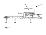
- Fig. 3 shows schematically the use of the concrete compulsory mixer 1 according to the invention in the production of linear structures, such. B. edging from curbs. This requires a Produce the concrete to meet the quality requirements and distribute linear according to the course of the edging.
- the vehicle picks up the aggregates within the construction site with the self-loading device 6 and mixes the concrete. It brings the finished concrete to the building and distributes it via the conveyor belt 7.
- the conveyor belt 7 causes a regular output of the concrete, which can not be achieved by slipping or similar devices. By the driving speed of the worker determines the amount of concrete organric density, thereby eliminating the tedious dispensing by hand.
- the self-propelled concrete compulsory mixer 1 is particularly advantageous if, as shown in Fig. 3, only one lane is available. On the left in Fig. 3 is denoted by 13 the finished offset edge enclosure, which delimits the lane for single-lane traffic 14 from the left sidewalk. Right in Fig. 3, the lane for the construction site traffic 15 is shown, on which the edge enclosure for the right sidewalk is built by means of the mobile combined concrete mixer 1 according to the invention.
- the mobile concrete mixer 1 according to the invention is able to produce good quality fresh concrete in earth-moist condition directly on the construction site and distributed linearly.
- This device is particularly suitable for use in road and paving, z. B. for the production of edge borders, smaller retaining walls and the like.
- the combination with the very agile, powerful carrier vehicle 2 and the conveyor belt 7 allows a fast and accurate distribution of ready-to-use concrete. Since the vehicle always runs parallel to the distribution direction, the space required is relatively small.
Landscapes
- Engineering & Computer Science (AREA)
- Structural Engineering (AREA)
- Mechanical Engineering (AREA)
- Architecture (AREA)
- Civil Engineering (AREA)
- Preparation Of Clay, And Manufacture Of Mixtures Containing Clay Or Cement (AREA)
- On-Site Construction Work That Accompanies The Preparation And Application Of Concrete (AREA)
Description
- Die Erfindung bezieht sich auf das Gebiet des Bauwesens. Sie betrifft einen selbstfahrenden kombinierten Betonzwangsmischer, welcher insbesondere für den Einsatz im Strassen- und Pflasterbau geeignet ist.
- Bekannt sind fahrbare Betonmischer, bei denen eine Trommel oder eine Rührwerksschüssel auf einem Fahrzeug montiert ist. Die Trommel bzw. die Rührwerksschüssel wird von einer stationären Zuteilanlage mit den Bestandteilen für das Betongemisch beladen. Durch Drehung der Trommel bzw. Schüssel vor und während des Transports zu einem Entladeort wird das Betongemisch gemischt und am Entladeort, d. h. der Baustelle, entladen.
- Nachteilig an derartigen mobilen Trommel- bzw. Rührwerksschüsselmischern ist, dass sie ihre gesamte Ladung abladen müssen, sobald sie an der Baustelle sind, und dass dies während einer relativ kurzen Zeitspanne durchgeführt werden muss. Dies ist nicht praktikabel für Verwender von Betongemischen, welche weniger als die vorgegebene Mischerzuteilungsgröße benötigen und/oder die Abgabe kleinerer Mengen an Beton über einen längeren Zeitraum hinweg benötigen. Ein weiterer Nachteil dieser bekannten Betonmischer ist der große Platzbedarf.
- Aus der Druckschrift
US 4,538,916 ist ein Fahrzeug bekannt, das als mobiles Zuteil- und Mischgerät arbeitet, um bei Bedarf unterschiedliche Mengen von vorgemischtem Beton bereitzustellen. Dazu ist auf dem Fahrgestell eines Lastwagens in senkrechter Position ein Zementbunker angeordnet. Des weiteren sind auf dem Lastwagen ein Wassertank und zwei Schüttgutbehälter für feste Zuschlagstoffe, z. B. Sand oder Kies angebracht. Über verschiedene Fördereinrichtungen werden Zement, Zuschlagstoffe und Wasser einem auf dem Lastwagen in schräger Position angeordneten Schneckenförderer zugeführt, in welchem die Stoffe dann zu Beton gemischt werden. Am Ende des Schneckenförderers wird der Beton entnommen und direkt vor Ort auf der Baustelle verarbeitet. - Das Dokument
DE-U-9308140 offenbart einen selbstfahrenden kombinierten Betonzwangsmischer, gemäß dem Oberbegriff des Anspruchs 1. - Weitere bisher bekannte Anbaumischer sind zwar in ihrer Anbaufähigkeit an die verschiedensten Trägergeräte, wie Schlepper, Gabelstapler, Raupen, Radlader usw. sehr flexibel einsetzbar, das Ausbringen des Betons direkt am Verwendungsort an der Baustelle ist jedoch bei all diesen Anbauvarianten sehr zeitintensiv.
- Beim Herstellen von linienförmigen Bauwerken, wie Randeinfassungen (Bordsteine, Pflasterbunde), kleineren Stützmauern aus Fertigteilen usw. ist es erforderlich, einen den Qualitätsanforderungen genügenden Beton herzustellen und entsprechend dem Verlauf der Randeinfassung linienförmig zu verteilen.
- Wegen der meist beengten Verhältnisse entlang von Straßen oder auf Gehwegen ist es sehr aufwändig am Lagerplatz hergestellten Beton mittels Radlader zu verteilen, da hierbei zunächst einzelne Betonhaufen gekippt werden, die dann von Hand in Linienform gebracht werden müssen. Dies ist äußerst zeitaufwändig. Beim Verteilen des Betons mittels Radlader ist nachteilig ein ständiges Rangieren notwendig.
- Ziel der Erfindung ist es, die eingangs genannten Nachteile des Standes der Technik zu vermeiden. Der Erfindung liegt die Aufgabe zu Grunde, einen fahrbaren kombinierten Betonzwangsmischer zu entwickeln, der in der Lage ist, einen qualitativ guten Frischbeton in erdfeuchtem Zustand direkt auf der Baustelle herzustellen und linienförmig zu verteilen. Er soll nur wenig Platz benötigen und ohne große Rangierarbeiten handhabbar sein, wobei die sachgerechte exakte Verteilung des Betons innerhalb kürzester Zeit gewährleistet sein soll.
- Erfindungsgemäß wird diese Aufgabe, durch die Merkmale des Anspruchs 1 gelöst und besteht der fahrbare kombinierte Betonzwangsmischer aus folgenden Einzelvorrichtungen:
- einem Trägerfahrzeug mit Allradantrieb und einem Fahrgestell, wobei das Trägerfahrzeug ein Knicklenker ist,
- einem (eigentlichen) Zwangsmischer mit einer vertikalen Mischerachse und einer auf seiner Unterseite angeordneten verschliessbaren Austragsöffnung, wobei der Zwangsmischer auf dem Fahrgestell des Trägerfahrzeuges aufgesetzt und fest montiert ist,
- einer am Fahrgestell des Trägerfahrzeuges oder am Zwangsmischer angebrachten Selbstladevorrichtung für den Zwangsmischer zur Aufnahme von Zuschlagstoffen und
- einem unterhalb der Austragsöffnung des Zwangsmischers gelenkig angeordneten Förderband zum Transport und zur exakten Verteilung des Fertigbetons.
- Die Vorteile des erfindungsgemäßen Betonzwangmischers bestehen darin, dass der Beton vor Ort, also innerhalb der Baustelle, effizient mittels des vertikalen Zwangsmischers gemischt und über das Förderband linienförmig verteilt werden kann. Das Förderband bewirkt eine regelmäßige Abgabe des Betons, was durch Rutschen oder ähnliche bekannte Vorrichtungen nicht erreicht werden kann. Durch die Fahrgeschwindigkeit bestimmt zudem der Arbeiter die Menge des auszubringenden Betons je Laufmeter, so dass das mühsame Verteilen von Hand entfällt.
- Da das Fahrzeug stets parallel zum Verlauf der Randeinfassung fährt, ist der Platzbedarf relativ gering. Ebenso entfällt das ständige Rangieren, wie es beim Verteilen mittels Radlader erforderlich ist um den Beton abkippen zu können. Der erfindungsgemäße Betonzwangsmischer ist insbesondere dann von Vorteil, wenn nur eine Fahrspur zur Verfügung steht.
- Dadurch, dass das selbstfahrende Trägerfahrzeug ein mit Allradantrieb ausgerüsteter Knicklenker ist, werden durch seine Wendigkeit und hohe Leistung optimale Bedingungen geschaffen.
- Weiterhin ist es vorteilhaft, dass zur Steuerung des Zwangsmischers, der Selbstladevorrichtung und des Förderbandes jeweils ein eigener hydraulischer Steuerkreis vorgesehen ist, wobei die besagten Steuerkreise vom Führerstand des Trägerfahrzeuges aus steuerbar sind. Es ist damit eine sehr gute Mischung des Betons, sowie exakte Dosierung und Verteilung an der Einbaustelle möglich.
- Von Vorteil ist, dass die Selbstladevorrichtung mindestens eine Rückstellfeder aufweist, mittels derer die Rückstellung der Selbstladevorrichtung aus der senkrechten Stellung beim Auskippen in den Zwangsmischer erfolgt. Somit reicht hier ein hydraulischer Steuerkreis zur Steuerung der Ladeschaufel der Selbstladevorrichtung aus.
- Weiterhin ist es zweckmäßig, wenn das unter dem Zwangsmischer fixierte Förderband in Gebrauchsstellung in Fahrtrichtung seitlich unter dem Zwangsmischer hervorragt und seine Höhenlage einfach mittels einer verstellbaren Kette fixierbar ist, während es in Nichtgebrauchsstellung, beispielsweise bei Transportfahrten, in die Senkrechte klappbar ist. Dann wird vorteilhaft wenig Platz benötigt.
- Schließlich ist es vorteilhaft, dass der Betonzwangsmischer aus einer Kombination von handelsüblichen Einzelvorrichtungen besteht.
- In der Zeichnung ist ein Ausführungsbeispiel der Erfindung dargestellt. Es zeigen:
- Fig. 1
- eine Seitenansicht des erfindungsgemäßen Betonzwangsmischers;
- Fig. 2
- einen Schnitt entlang der Linie II-II in Fig. 1 und
- Fig.3
- eine schematische Darstellung des erfindungsgemäßen Betonzwangsmischers während seines Einsatzes bei der Herstellung einer linienförmigen Randeinfassung.
- In den Figuren sind jeweils gleiche Positionen mit den gleichen Bezugszeichen versehen. Es sind nur die für die Erfindung wesentlichen Merkmale dargestellt.
- Nachfolgend wird die Erfindung anhand eines Ausführungsbeispieles und der Fig. 1 bis 3 näher erläutert.
- In Fig. 1 ist der erfindungsgemäße selbstfahrende kombinierte Betonzwangsmischer 1 komplett in einer Seitenansicht dargestellt, Fig. 2 zeigt einen Schnitt entlang der Linie II-II. Zum besseren Verständnis der Erfindung ist es zweckmäßig, beide Figuren gleichzeitig zu betrachten.
- Der Betonzwangsmischer 1 ist eine kombinierte Vorrichtung, welche im wesentlichen aus einem selbstfahrenden Trägerfahrzeug 2, einem eigentlichen Zwangsmischer 3 mit in einer in Fig. 1 nicht, aber in Fig. 2 sichtbaren vertikalen Mischerachse 4 angeordneten Mitteln zum Mischen 5 der Ausgangs-/Zuschlagstoffe für den herzustellenden Beton, sowie aus einer Selbstladevorrichtung 6 und einem Förderband 7 besteht.
- Das Trägerfahrzeug 2 ist mit Allradantrieb ausgestattet. Das Trägerfahrzeug 2 ist ein Knicklenker, z. B. ein handelsüblicher Dumper mit abmontierter Wanne, der durch seine Wendigkeit und hohe Leistung beim Einsatz auf der Baustelle vorteilhaft einsetzbar ist.
- Auf dem Fahrgestell 8 des Trägerfahrzeuges 2 ist der Zwangsmischer 3 mit vertikaler Mischerachse 4 aufgesetzt und fest montiert.
- Der Antrieb des Zwangsmischers 3 erfolgt über ein in den Figuren nicht dargestelltes Hydraulikgetriebe, dessen Öldruck vom Trägerfahrzeug 2 erzeugt wird. Die Mittel zum Mischen 5, beispielsweise ein Rührwerk, werden in Drehbewegung versetzt, mischen dadurch die Ausgangs-/Zuschlagstoffe und stellen letztlich den einsatzbereiten Beton her.
- Das Bindemittel (Zement) sowie das Zuschlagswasser werden direkt in die Rührschüssel gegeben. Die Rührschüssel ist mit einem stabilen Gitter (nicht in den Figuren dargestellt), welches eine Maschenweite von ca. 50 - 70 mm aufweist, abgedeckt und kreuzweise mit Zahnschienen versehen. Dadurch wird einerseits ein unbeabsichtigtes Hineingreifen in die Rührvorrichtung verhindert. Andererseits kann die Sackware auf den Zahnschienen aufgerissen werden, der Zement fällt durch das Gitter in die Rührschüssel, während der Papiersack auf dem Gitter zurückbleibt und ohne Gefahr entfernt werden kann.
- Die Beladung des Zwangsmischers 3 mit den für die Betonherstellung notwendigen Zuschlagstoffen erfolgt über die Selbstladevorrichtung 6. Diese ist entweder direkt am Zwangsmischer 3 oder am Fahrgestell 8 des Trägerfahrzeuges 2 angebracht. Im vorliegenden Ausführungsbeispiel ist sie am Fahrgestell 8 des Dumpers angebracht, und zwar an dem in Fahrtrichtung vorn liegenden Teil des Fahrgestelles, d. h. an dem dem Führerstand 11 gegenüberliegenden Ende.
- Die Selbstladevorrichtung 6 wird durch einen weiteren separaten hydraulischen Steuerkreis betrieben. Sie ist so konstruiert, dass ein einziger hydraulischer Steuerkreis genügt, um die Ladeschaufel zu steuern. Die Rückstellung der Selbstladevorrichtung 6 aus der senkrechten Stellung (beim Auskippen in den Zwangsmischer 3) erfolgt über eine starke Rückstellfeder 9.
- Der Zwangsmischer 3 weist an seiner Unterseite eine beispielweise mittels eines Schiebers verschließbare Austragsöffnung 10 auf. Bei Bedarf wird diese Austragsöffnung 10 geöffnet und der Zwangsmischer 3 wird über das unterhalb der Austragsöffnung 10 in seitliche Richtung zur Fahrtrichtung angeordnete Förderband 7 entleert. Dies ermöglicht eine exakte Dosierung und genaue Verteilung des Betons an der Baustelle. Das Förderband 7 wird ebenfalls durch einen eigenen Steuerkreis hydraulisch angetrieben.
- Somit sind insgesamt 3 Steuerkreise für den Betrieb des erfindungsgemäßen Betonzwangsmischers 1 erforderlich. Die Steuerung aller drei Steuerkreise erfolgt vom Führerstand 11 des Trägerfahrzeugs 2 aus.
- Das Förderband 7 ist gelenkig unter dem Auslassschieber/der Austragsöffnung 10 befestigt. Es kann bei Transportfahrten ganz in die Senkrechte geklappt werden, so dass der mobile Betonzwangsmischer 1 nur wenig Platz benötigt. Beim Ausbringen des Betons wird die Höhenlage des Förderbandes 7 mit einer verstellbaren Kette 12 fixiert.
- Fig. 3 zeigt schematisch den Einsatz des erfindungsgemäßen Betonzwangsmischers 1 bei der Herstellung von linienförmigen Bauwerken, wie z. B. Randeinfassungen aus Bordsteinen. Dazu ist es erforderlich, einen den Qualitätsanforderungen genügenden Beton herzustellen und entsprechend dem Verlauf der Randeinfassung linienförmig zu verteilen.
- Das Fahrzeug nimmt mit der Selbstladevorrichtung 6 die Zuschlagsstoffe innerhalb der Baustelle auf und mischt den Beton. Es bringt den fertigen Beton zum Bauwerk und verteilt ihn über das Förderband 7. Das Förderband 7 bewirkt eine regelmäßige Ausgabe des Betons, was durch Rutschen oder ähnliche Vorrichtungen nicht erreicht werden kann. Durch die Fahrgeschwindigkeit bestimmt der Arbeiter die Menge des auszubringenden Betons je Laufmeter, dadurch entfällt das mühsame Verteilen von Hand.
- Da der kombinierte Betonzwangsmischer 1 stets parallel zum Verlauf der Randeinfassung fährt, ist der Platzbedarf relativ gering. Ebenso entfällt das ständige Rangieren, wie es beim Verteilen mittels Radlader erforderlich ist um den Beton abkippen zu können. Der selbstfahrende Betonzwangsmischer 1 ist insbesondere dann von Vorteil, wenn wie in Fig. 3 dargestellt, nur eine Fahrspur zur Verfügung steht. Links in Fig. 3 ist mit 13 die fertig versetzte Randeinfassung bezeichnet, welche die Fahrspur für einspurigen Verkehr 14 vom linken Gehweg abgrenzt. Rechts in Fig. 3 ist die Fahrspur für den Baustellenverkehr 15 dargestellt, auf der die Randeinfassung für den rechten Gehweg mittels des erfindungsgemäßen fahrbaren kombinierten Betonzwangsmischers 1 gebaut wird.
- Die erfindungsgemäße mobile Betonmischer 1 ist in der Lage, qualitativ guten Frischbeton in erdfeuchtem Zustand direkt auf der Baustelle herzustellen und linienförmig zu verteilen. Diese Vorrichtung ist insbesondere für den Einsatz im Straßen- und Pflasterbau geeignet, z. B. für die Herstellung von Randeinfassungen, kleineren Stützmauern und dgl.
- Die Kombination mit dem sehr wendigen, leistungsstarken Trägerfahrzeug 2 und dem Förderband 7 lässt eine schnelle und exakte Verteilung des einsatzbereiten Betons zu. Da das Fahrzeug stets parallel zur Verteilrichtung fährt, ist der Platzbedarf verhältnismäßig gering.
- Selbstverständlich ist die Erfindung nicht auf das beschriebene Ausführungsbeispiel beschränkt.
-
- 1
- Kombinierter Betonzwangsmischer
- 2
- Trägerfahrzeug
- 3
- Zwangsmischer
- 4
- vertikale Mischerachse
- 5
- Mittel zum Mischen
- 6
- Selbstladevorrichtung
- 7
- Förderband
- 8
- Fahrgestell
- 9
- Rückstellfeder
- 10
- Verschließbare Austragsöffnung
- 11
- Führerstand
- 12
- Kette
- 13
- Fertig versetzte Randeinfassung
- 14
- Fahrspur für einspurigen Verkehr
- 15
- Fahrspur für Baustellenverkehr
- H
- Höhenlage des Förderbandes
Claims (7)
- Selbstfahrender kombinierter Betonzwangsmischer (1), bestehend aus- einem Trägerfahrzeug (2) mit Allradantrieb und einem Fahrgestell (8),- einem Zwangsmischer (3) mit in einer vertikalen Mischerachse (4) angeordneten Mitteln (5) zum Mischen,- einer am Fahrgestell (8) des Trägerfahrzeuges (2) oder am Zwangsmischer (3) angebrachten Selbstladevorrichtung (6) für den Zwangsmischer (3) zur Aufnahme von Zuschlagstoffen für die Betonherstellung,dadurch gekennzeichnet, daß- das Trägerfahrzeug (2) ein Knicklenker ist,- der Zwangsmischer (3) eine auf seiner Unterseite angeordnete verschließbare Austragsöffnung (10) hat, wobei der Zwangsmischer (3) auf dem Fahrgestell (8) des Trägerfahrzeuges (2) aufgesetzt und fest montiert ist,- unterhalb der Austragsöffnung (10) des Zwangsmischers (3) ein Förderband (7) zum Transport und zur exakten Verteilung des Fertigbetons gelenkig angeordnet ist.
- Betonzwangsmischer (1) nach Anspruch 1, dadurch gekennzeichnet, dass zur Steuerung des Zwangsmischers (3), der Selbstladevorrichtung (6) und des Förderbandes (7) jeweils ein eigener hydraulischer Steuerkreis vorgesehen ist.
- Betonzwangsmischer (1) nach Anspruch 2, dadurch gekennzeichnet, dass die besagten Steuerkreise vom Führerstand (12) des Trägerfahrzeuges (2) aus steuerbar sind.
- Betonzwangsmischer (1) nach Anspruch 1, dadurch gekennzeichnet, dass die Selbstladevorrichtung (6) mindestens eine Rückstellfeder (9) aufweist, mittels derer die Rückstellung der Selbstladevorrichtung (6) aus der senkrechten Stellung beim Auskippen in den Zwangsmischer (3) erfolgt.
- Betonzwangsmischer (1) nach Anspruch 1, dadurch gekennzeichnet, dass das Förderband (7) in Gebrauchsstellung seitlich in Fahrtrichtung unter dem Zwangsmischer (3) angeordnet ist und seine Höhenlage (H) mittels einer verstellbaren Kette (12) fixierbar ist.
- Betonzwangsmischer (1) nach Anspruch 1, dadurch gekennzeichnet, dass das Förderband (7) in Nichtgebrauchssteltung in die Senkrechte klappbar ist.
- Betonzwangsmischer (1) nach Anspruch 1, dadurch gekennzeichnet, dass er aus einer Kombination von handelsüblichen Einzelvorrichtungen besteht.
Priority Applications (3)
| Application Number | Priority Date | Filing Date | Title |
|---|---|---|---|
| DE502004004721T DE502004004721D1 (de) | 2004-03-07 | 2004-03-07 | Selbstfahrender kombinierter Betonzwangsmischer |
| AT04005351T ATE371056T1 (de) | 2004-03-07 | 2004-03-07 | Selbstfahrender kombinierter betonzwangsmischer |
| EP04005351A EP1574620B1 (de) | 2004-03-07 | 2004-03-07 | Selbstfahrender kombinierter Betonzwangsmischer |
Applications Claiming Priority (1)
| Application Number | Priority Date | Filing Date | Title |
|---|---|---|---|
| EP04005351A EP1574620B1 (de) | 2004-03-07 | 2004-03-07 | Selbstfahrender kombinierter Betonzwangsmischer |
Publications (2)
| Publication Number | Publication Date |
|---|---|
| EP1574620A1 EP1574620A1 (de) | 2005-09-14 |
| EP1574620B1 true EP1574620B1 (de) | 2007-08-22 |
Family
ID=34814250
Family Applications (1)
| Application Number | Title | Priority Date | Filing Date |
|---|---|---|---|
| EP04005351A Expired - Lifetime EP1574620B1 (de) | 2004-03-07 | 2004-03-07 | Selbstfahrender kombinierter Betonzwangsmischer |
Country Status (3)
| Country | Link |
|---|---|
| EP (1) | EP1574620B1 (de) |
| AT (1) | ATE371056T1 (de) |
| DE (1) | DE502004004721D1 (de) |
Families Citing this family (5)
| Publication number | Priority date | Publication date | Assignee | Title |
|---|---|---|---|---|
| FR2909394B1 (fr) * | 2006-12-01 | 2010-08-20 | Drapeau Ets | Dispositif de dosage, de malaxage et de distribution de beton pour la realisation d'une surface plane |
| CN110344302B (zh) * | 2018-04-02 | 2021-02-09 | 利越集团有限公司 | 道路石油沥青混合料级配调试装置及方法 |
| DE102019109010A1 (de) * | 2019-04-05 | 2020-10-08 | Belmix Operating Services Sa | Mobiles System zum Bevorraten, Mischen und Pumpen mischbarer Bestandteile insbesondere zur Herstellung von Beton, Mörtel und Estrich, Verfahren zur Verwendung des mobilen Systems |
| CN113235379A (zh) * | 2021-06-29 | 2021-08-10 | 黑龙江省八达路桥建设有限公司 | 一种混凝土路面施工修补装置 |
| CN118342652A (zh) * | 2024-05-27 | 2024-07-16 | 扬州宝盛建材有限公司 | 一种混凝土搅拌装置 |
Family Cites Families (5)
| Publication number | Priority date | Publication date | Assignee | Title |
|---|---|---|---|---|
| DE1302135B (de) * | 1967-01-26 | |||
| FR2157516A5 (de) * | 1971-10-16 | 1973-06-01 | Ormi | |
| US4268175A (en) * | 1980-02-07 | 1981-05-19 | Norlie Robert N | Tractor mounted self-loading concrete mixing apparatus |
| DE9308140U1 (de) * | 1993-05-27 | 1993-07-29 | Fliegl, Josef, 84556 Kastl | Füllvorrichtung für eine Mischmaschine |
| DE29908493U1 (de) * | 1999-05-12 | 1999-11-25 | Sax, Albert, 84036 Landshut | Transportable Mischanlage für Beton und/oder Mörtel |
-
2004
- 2004-03-07 DE DE502004004721T patent/DE502004004721D1/de not_active Expired - Lifetime
- 2004-03-07 EP EP04005351A patent/EP1574620B1/de not_active Expired - Lifetime
- 2004-03-07 AT AT04005351T patent/ATE371056T1/de not_active IP Right Cessation
Non-Patent Citations (1)
| Title |
|---|
| None * |
Also Published As
| Publication number | Publication date |
|---|---|
| ATE371056T1 (de) | 2007-09-15 |
| EP1574620A1 (de) | 2005-09-14 |
| DE502004004721D1 (de) | 2007-10-04 |
Similar Documents
| Publication | Publication Date | Title |
|---|---|---|
| EP0597176B1 (de) | Verfahren und Vorrichtung zur Sanierung beschädigter Fahrbahnen | |
| DE69528537T2 (de) | FAHRBARER BETONMiSCHAPPARAT UND VERTEILERSYSTEM | |
| EP2218823B2 (de) | Stabilisierer oder Recycler | |
| DE2856635A1 (de) | Maschine zum beschichten von abgefraesten oder abgeschaelten strassendecken | |
| EP1012396B1 (de) | Maschine zum bearbeiten von fahrbahnen | |
| EP1574620A1 (de) | Selbstfahrender kombinierter Betonzwangsmischer | |
| DE102016002644A1 (de) | Hydraulisch angetriebener Zwangsmischer | |
| DE102009016518A1 (de) | Transportfahrzeug zur Anlieferung eines Bindemittel/Zuschlagsgemischs | |
| DE4206994C2 (de) | Verfahren und Vorrichtung zur Stabilisierung beschädigter Straßendecken | |
| DE102004006624B4 (de) | Vorrichtung und Verfahren zur Herstellung von flüssigem, bituminösem Kaltmischgut | |
| DE9316365U1 (de) | Streufahrzeug | |
| EP0467255B1 (de) | Motorgetriebenes Verlegefahrzeug für Fahrbahn- oder Wege-Beläge | |
| DE202019106035U1 (de) | Vermengungsvorrichtung für ein landwirtschaftliches Fahrzeug | |
| DE29818934U1 (de) | Vorrichtung zur Herstellung gebrauchsfertiger Mischungen aus Schüttgut | |
| DE60000529T2 (de) | Verfahren und Vorrichtung zur Behandlung von Materialien hauptsächlich bestehend aus feuchtem Ton, insbesondere Bodenaushub | |
| DE2830056A1 (de) | Streueinrichtung fuer lastfahrzeuge | |
| WO1995018706A1 (de) | Anlage zur betonherstellung in einem tunnel | |
| DE102004027454B4 (de) | Materialspeicher zur Annahme und Abgabe von Schüttgütern | |
| WO1999055969A1 (de) | Vorrichtung zum bearbeiten von fahrbahnen | |
| DE3247233A1 (de) | Verfahren und vorrichtung zur aufbereitung eines gemisches aus sand, bindemitteln, wasser und ggf. weiteren zusaetzen fuer die verarbeitung zu estrich, insbesondere fliessestrich | |
| DE8910379U1 (de) | Straßentransportfahrzeug für heißes bituminöses Mischgut od.dgl. | |
| DE102019109010A1 (de) | Mobiles System zum Bevorraten, Mischen und Pumpen mischbarer Bestandteile insbesondere zur Herstellung von Beton, Mörtel und Estrich, Verfahren zur Verwendung des mobilen Systems | |
| WO2004078438A1 (de) | Transportfahrzeug und verfahren zur anlieferung eines bindemittel/zuschlagsgemischs | |
| DE3011867A1 (de) | Transportbetonmischer | |
| AT398997B (de) | Verfahren zur herstellung von dünnen decken auf bodenflächen, insbesondere verkehrsflächen |
Legal Events
| Date | Code | Title | Description |
|---|---|---|---|
| PUAI | Public reference made under article 153(3) epc to a published international application that has entered the european phase |
Free format text: ORIGINAL CODE: 0009012 |
|
| 17P | Request for examination filed |
Effective date: 20050329 |
|
| AK | Designated contracting states |
Kind code of ref document: A1 Designated state(s): AT BE BG CH CY CZ DE DK EE ES FI FR GB GR HU IE IT LI LU MC NL PL PT RO SE SI SK TR |
|
| AX | Request for extension of the european patent |
Extension state: AL LT LV MK |
|
| AKX | Designation fees paid |
Designated state(s): AT BE BG CH CY CZ DE DK EE ES FI FR GB GR HU IE IT LI LU MC NL PL PT RO SE SI SK TR |
|
| GRAP | Despatch of communication of intention to grant a patent |
Free format text: ORIGINAL CODE: EPIDOSNIGR1 |
|
| GRAS | Grant fee paid |
Free format text: ORIGINAL CODE: EPIDOSNIGR3 |
|
| GRAA | (expected) grant |
Free format text: ORIGINAL CODE: 0009210 |
|
| AK | Designated contracting states |
Kind code of ref document: B1 Designated state(s): AT BE BG CH CY CZ DE DK EE ES FI FR GB GR HU IE IT LI LU MC NL PL PT RO SE SI SK TR |
|
| REG | Reference to a national code |
Ref country code: GB Ref legal event code: FG4D Free format text: NOT ENGLISH |
|
| REG | Reference to a national code |
Ref country code: CH Ref legal event code: EP |
|
| REG | Reference to a national code |
Ref country code: IE Ref legal event code: FG4D Free format text: LANGUAGE OF EP DOCUMENT: GERMAN |
|
| REF | Corresponds to: |
Ref document number: 502004004721 Country of ref document: DE Date of ref document: 20071004 Kind code of ref document: P |
|
| GBT | Gb: translation of ep patent filed (gb section 77(6)(a)/1977) |
Effective date: 20071129 |
|
| PG25 | Lapsed in a contracting state [announced via postgrant information from national office to epo] |
Ref country code: NL Free format text: LAPSE BECAUSE OF FAILURE TO SUBMIT A TRANSLATION OF THE DESCRIPTION OR TO PAY THE FEE WITHIN THE PRESCRIBED TIME-LIMIT Effective date: 20070822 Ref country code: FI Free format text: LAPSE BECAUSE OF FAILURE TO SUBMIT A TRANSLATION OF THE DESCRIPTION OR TO PAY THE FEE WITHIN THE PRESCRIBED TIME-LIMIT Effective date: 20070822 Ref country code: ES Free format text: LAPSE BECAUSE OF FAILURE TO SUBMIT A TRANSLATION OF THE DESCRIPTION OR TO PAY THE FEE WITHIN THE PRESCRIBED TIME-LIMIT Effective date: 20071203 Ref country code: BG Free format text: LAPSE BECAUSE OF FAILURE TO SUBMIT A TRANSLATION OF THE DESCRIPTION OR TO PAY THE FEE WITHIN THE PRESCRIBED TIME-LIMIT Effective date: 20071122 |
|
| NLV1 | Nl: lapsed or annulled due to failure to fulfill the requirements of art. 29p and 29m of the patents act | ||
| PG25 | Lapsed in a contracting state [announced via postgrant information from national office to epo] |
Ref country code: PL Free format text: LAPSE BECAUSE OF FAILURE TO SUBMIT A TRANSLATION OF THE DESCRIPTION OR TO PAY THE FEE WITHIN THE PRESCRIBED TIME-LIMIT Effective date: 20070822 |
|
| REG | Reference to a national code |
Ref country code: IE Ref legal event code: FD4D |
|
| ET | Fr: translation filed | ||
| PG25 | Lapsed in a contracting state [announced via postgrant information from national office to epo] |
Ref country code: DK Free format text: LAPSE BECAUSE OF FAILURE TO SUBMIT A TRANSLATION OF THE DESCRIPTION OR TO PAY THE FEE WITHIN THE PRESCRIBED TIME-LIMIT Effective date: 20070822 Ref country code: GR Free format text: LAPSE BECAUSE OF FAILURE TO SUBMIT A TRANSLATION OF THE DESCRIPTION OR TO PAY THE FEE WITHIN THE PRESCRIBED TIME-LIMIT Effective date: 20071123 |
|
| PG25 | Lapsed in a contracting state [announced via postgrant information from national office to epo] |
Ref country code: PT Free format text: LAPSE BECAUSE OF FAILURE TO SUBMIT A TRANSLATION OF THE DESCRIPTION OR TO PAY THE FEE WITHIN THE PRESCRIBED TIME-LIMIT Effective date: 20080122 Ref country code: SK Free format text: LAPSE BECAUSE OF FAILURE TO SUBMIT A TRANSLATION OF THE DESCRIPTION OR TO PAY THE FEE WITHIN THE PRESCRIBED TIME-LIMIT Effective date: 20070822 Ref country code: CZ Free format text: LAPSE BECAUSE OF FAILURE TO SUBMIT A TRANSLATION OF THE DESCRIPTION OR TO PAY THE FEE WITHIN THE PRESCRIBED TIME-LIMIT Effective date: 20070822 Ref country code: IE Free format text: LAPSE BECAUSE OF FAILURE TO SUBMIT A TRANSLATION OF THE DESCRIPTION OR TO PAY THE FEE WITHIN THE PRESCRIBED TIME-LIMIT Effective date: 20070822 |
|
| PLBE | No opposition filed within time limit |
Free format text: ORIGINAL CODE: 0009261 |
|
| STAA | Information on the status of an ep patent application or granted ep patent |
Free format text: STATUS: NO OPPOSITION FILED WITHIN TIME LIMIT |
|
| PG25 | Lapsed in a contracting state [announced via postgrant information from national office to epo] |
Ref country code: RO Free format text: LAPSE BECAUSE OF FAILURE TO SUBMIT A TRANSLATION OF THE DESCRIPTION OR TO PAY THE FEE WITHIN THE PRESCRIBED TIME-LIMIT Effective date: 20070822 Ref country code: SE Free format text: LAPSE BECAUSE OF FAILURE TO SUBMIT A TRANSLATION OF THE DESCRIPTION OR TO PAY THE FEE WITHIN THE PRESCRIBED TIME-LIMIT Effective date: 20071122 |
|
| 26N | No opposition filed |
Effective date: 20080526 |
|
| BERE | Be: lapsed |
Owner name: KAISER G.M.B.H. PFLASTER- UND NATURSTEINBAU Effective date: 20080331 |
|
| PG25 | Lapsed in a contracting state [announced via postgrant information from national office to epo] |
Ref country code: MC Free format text: LAPSE BECAUSE OF NON-PAYMENT OF DUE FEES Effective date: 20080331 |
|
| PG25 | Lapsed in a contracting state [announced via postgrant information from national office to epo] |
Ref country code: EE Free format text: LAPSE BECAUSE OF FAILURE TO SUBMIT A TRANSLATION OF THE DESCRIPTION OR TO PAY THE FEE WITHIN THE PRESCRIBED TIME-LIMIT Effective date: 20070822 |
|
| PG25 | Lapsed in a contracting state [announced via postgrant information from national office to epo] |
Ref country code: BE Free format text: LAPSE BECAUSE OF NON-PAYMENT OF DUE FEES Effective date: 20080331 |
|
| REG | Reference to a national code |
Ref country code: CH Ref legal event code: NV Representative=s name: DR. JOACHIM LAUER PATENTANWALT |
|
| PG25 | Lapsed in a contracting state [announced via postgrant information from national office to epo] |
Ref country code: SI Free format text: LAPSE BECAUSE OF FAILURE TO SUBMIT A TRANSLATION OF THE DESCRIPTION OR TO PAY THE FEE WITHIN THE PRESCRIBED TIME-LIMIT Effective date: 20070822 |
|
| PG25 | Lapsed in a contracting state [announced via postgrant information from national office to epo] |
Ref country code: CY Free format text: LAPSE BECAUSE OF FAILURE TO SUBMIT A TRANSLATION OF THE DESCRIPTION OR TO PAY THE FEE WITHIN THE PRESCRIBED TIME-LIMIT Effective date: 20070822 |
|
| PG25 | Lapsed in a contracting state [announced via postgrant information from national office to epo] |
Ref country code: AT Free format text: LAPSE BECAUSE OF NON-PAYMENT OF DUE FEES Effective date: 20080307 |
|
| PG25 | Lapsed in a contracting state [announced via postgrant information from national office to epo] |
Ref country code: HU Free format text: LAPSE BECAUSE OF FAILURE TO SUBMIT A TRANSLATION OF THE DESCRIPTION OR TO PAY THE FEE WITHIN THE PRESCRIBED TIME-LIMIT Effective date: 20080223 Ref country code: LU Free format text: LAPSE BECAUSE OF NON-PAYMENT OF DUE FEES Effective date: 20080307 |
|
| PG25 | Lapsed in a contracting state [announced via postgrant information from national office to epo] |
Ref country code: TR Free format text: LAPSE BECAUSE OF FAILURE TO SUBMIT A TRANSLATION OF THE DESCRIPTION OR TO PAY THE FEE WITHIN THE PRESCRIBED TIME-LIMIT Effective date: 20070822 |
|
| REG | Reference to a national code |
Ref country code: CH Ref legal event code: PCAR Free format text: DR. JOACHIM LAUER C/O RENTSCH PARTNER AG;FRAUMUENSTERSTRASSE 9 POSTFACH 2441;8022 ZUERICH (CH) |
|
| REG | Reference to a national code |
Ref country code: FR Ref legal event code: PLFP Year of fee payment: 13 |
|
| REG | Reference to a national code |
Ref country code: FR Ref legal event code: PLFP Year of fee payment: 14 |
|
| REG | Reference to a national code |
Ref country code: CH Ref legal event code: PCAR Free format text: NEW ADDRESS: BELLERIVESTRASSE 203 POSTFACH, 8034 ZUERICH (CH) |
|
| REG | Reference to a national code |
Ref country code: FR Ref legal event code: PLFP Year of fee payment: 15 |
|
| PGFP | Annual fee paid to national office [announced via postgrant information from national office to epo] |
Ref country code: GB Payment date: 20180314 Year of fee payment: 15 Ref country code: DE Payment date: 20180208 Year of fee payment: 15 Ref country code: CH Payment date: 20180321 Year of fee payment: 15 |
|
| PGFP | Annual fee paid to national office [announced via postgrant information from national office to epo] |
Ref country code: FR Payment date: 20180328 Year of fee payment: 15 Ref country code: IT Payment date: 20180313 Year of fee payment: 15 |
|
| REG | Reference to a national code |
Ref country code: DE Ref legal event code: R119 Ref document number: 502004004721 Country of ref document: DE |
|
| REG | Reference to a national code |
Ref country code: CH Ref legal event code: PL |
|
| GBPC | Gb: european patent ceased through non-payment of renewal fee |
Effective date: 20190307 |
|
| PG25 | Lapsed in a contracting state [announced via postgrant information from national office to epo] |
Ref country code: LI Free format text: LAPSE BECAUSE OF NON-PAYMENT OF DUE FEES Effective date: 20190331 Ref country code: GB Free format text: LAPSE BECAUSE OF NON-PAYMENT OF DUE FEES Effective date: 20190307 Ref country code: DE Free format text: LAPSE BECAUSE OF NON-PAYMENT OF DUE FEES Effective date: 20191001 Ref country code: CH Free format text: LAPSE BECAUSE OF NON-PAYMENT OF DUE FEES Effective date: 20190331 |
|
| PG25 | Lapsed in a contracting state [announced via postgrant information from national office to epo] |
Ref country code: IT Free format text: LAPSE BECAUSE OF NON-PAYMENT OF DUE FEES Effective date: 20190307 Ref country code: FR Free format text: LAPSE BECAUSE OF NON-PAYMENT OF DUE FEES Effective date: 20190331 |