EP1574423A1 - Front structure for a motor vehicle - Google Patents
Front structure for a motor vehicle Download PDFInfo
- Publication number
- EP1574423A1 EP1574423A1 EP05004096A EP05004096A EP1574423A1 EP 1574423 A1 EP1574423 A1 EP 1574423A1 EP 05004096 A EP05004096 A EP 05004096A EP 05004096 A EP05004096 A EP 05004096A EP 1574423 A1 EP1574423 A1 EP 1574423A1
- Authority
- EP
- European Patent Office
- Prior art keywords
- fender
- front structure
- filler
- body part
- deformation
- Prior art date
- Legal status (The legal status is an assumption and is not a legal conclusion. Google has not performed a legal analysis and makes no representation as to the accuracy of the status listed.)
- Granted
Links
- 239000000945 filler Substances 0.000 claims abstract description 64
- 239000002184 metal Substances 0.000 claims abstract description 8
- 239000004033 plastic Substances 0.000 claims abstract description 6
- 229920001971 elastomer Polymers 0.000 claims description 3
- 230000001747 exhibiting effect Effects 0.000 claims 1
- 238000010276 construction Methods 0.000 description 8
- 238000002485 combustion reaction Methods 0.000 description 3
- 239000000853 adhesive Substances 0.000 description 2
- 230000001070 adhesive effect Effects 0.000 description 2
- 239000007789 gas Substances 0.000 description 2
- 238000003466 welding Methods 0.000 description 2
- QNRATNLHPGXHMA-XZHTYLCXSA-N (r)-(6-ethoxyquinolin-4-yl)-[(2s,4s,5r)-5-ethyl-1-azabicyclo[2.2.2]octan-2-yl]methanol;hydrochloride Chemical compound Cl.C([C@H]([C@H](C1)CC)C2)CN1[C@@H]2[C@H](O)C1=CC=NC2=CC=C(OCC)C=C21 QNRATNLHPGXHMA-XZHTYLCXSA-N 0.000 description 1
- 239000011324 bead Substances 0.000 description 1
- 230000005540 biological transmission Effects 0.000 description 1
- 229920001821 foam rubber Polymers 0.000 description 1
- 238000009413 insulation Methods 0.000 description 1
- 238000004519 manufacturing process Methods 0.000 description 1
- 239000000463 material Substances 0.000 description 1
Images

Classifications
-
- B—PERFORMING OPERATIONS; TRANSPORTING
- B60—VEHICLES IN GENERAL
- B60R—VEHICLES, VEHICLE FITTINGS, OR VEHICLE PARTS, NOT OTHERWISE PROVIDED FOR
- B60R21/00—Arrangements or fittings on vehicles for protecting or preventing injuries to occupants or pedestrians in case of accidents or other traffic risks
- B60R21/34—Protecting non-occupants of a vehicle, e.g. pedestrians
-
- B—PERFORMING OPERATIONS; TRANSPORTING
- B62—LAND VEHICLES FOR TRAVELLING OTHERWISE THAN ON RAILS
- B62D—MOTOR VEHICLES; TRAILERS
- B62D25/00—Superstructure or monocoque structure sub-units; Parts or details thereof not otherwise provided for
- B62D25/08—Front or rear portions
- B62D25/16—Mud-guards or wings; Wheel cover panels
- B62D25/163—Mounting devices
-
- B—PERFORMING OPERATIONS; TRANSPORTING
- B60—VEHICLES IN GENERAL
- B60R—VEHICLES, VEHICLE FITTINGS, OR VEHICLE PARTS, NOT OTHERWISE PROVIDED FOR
- B60R21/00—Arrangements or fittings on vehicles for protecting or preventing injuries to occupants or pedestrians in case of accidents or other traffic risks
- B60R21/34—Protecting non-occupants of a vehicle, e.g. pedestrians
- B60R2021/343—Protecting non-occupants of a vehicle, e.g. pedestrians using deformable body panel, bodywork or components
Definitions
- the invention relates to a front construction for a Motor vehicle with seen in the intended direction of travel front fenders, with one at a distance below the fenders arranged body part and with a between the Body part and the fenders arranged deformation device.
- Such a front end is for example from the DE 29 34 060 A1 known.
- the deformation device of this front construction has a semi-circular curved in cross-section Sheet metal between the inner edge of the fender and the underneath lying body part. Beats in an accident the Head of a pedestrian vertical to the fender, takes the Deformation the impact energy, causing the Head impact should be soft.
- EP 1 129 928 B1 a front construction become known, in which the deformation device also a semicircular, the fender vertical supporting Sheet metal as well as a between the body part and a Side of the wing has arranged supporting part.
- EP 1 132 263 A1 a fender arrangement known for a motor vehicle, in which a plate connected to the fender several individual tabs has as deformation members. That's the deformation links having sheet metal is about an adhesive bead with connected to the fender and supports it from the side.
- a disadvantage of the fender arrangement is that a inaccurate adhesive application to a deformation of the fender can lead. Continue to penetrate in this fender arrangement between the flaps engine noise to the outside.
- the invention is based on the problem, a Front of the type mentioned above to be designed so that he designed sufficiently resilient in a pedestrian impact is, but has sufficient stability during operation.
- the deformation device is a resilient, made of plastic manufactured filler and that the filler a gap between the body part and the fender closes.
- This design allows the rigidity the deformation device at the individual points of the fender by a corresponding embodiment of the filler to adjust.
- the filler can support the fender flat and thus occurring during operation of the motor vehicle To absorb forces.
- An additional panel to be arranged to prevent leakage of engine noise between the fender and the body part is thanks to the invention not necessary, because the filler with appropriate choice of material soundproofing and can be designed by the Deformation members generated gap between the body part and fenders concealed.
- the deformation device only the filler on.
- the deformation device carries it according to an advantageous Further development of the invention, when the deformation device made of sheet metal deformation members and if the filler between the deformation members is arranged. Through this design can be in addition to the filler, the deformation members made of sheet metal order at designated locations where one exclusive support by the filler only inadequate is.
- the assembly of the front building according to the invention requires a particularly low cost when the filler is made in one piece.
- the filler can according to an advantageous development the invention a transmission of sound very strongly dam when the filler at its on the fender adjacent side has a layer of sponge rubber.
- Front construction contributes to it, if the filler with glued to the body part and / or the fender.
- An abutment of the fenders to one between the Fenders arranged hood by leaning or a Laundry of the motor vehicle can be according to another advantageous Simply avoid development of the invention when the filler laterally supports the fender.
- the filler In order to takes the filler introduced laterally into the fender Forces up.
- the filler is at least partially between the side area of the fenders and the body part to arrange.
- a leakage of engine compartment gases between the fender and the body part can be according to another simply avoid an advantageous development of the invention if the filler the space between the fender and the Closes body part gas-tight.
- Determining the stability of the filler at A head impact on the fender is designed according to a another advantageous embodiment of the invention particularly easy if the filler has deformation bars.
- the deformation bars can, for example, honeycomb or circular segment or formed as a vertical buckling bars be.
- the Deformationsstege can be according to another advantageous development of the invention with very large Dimensions provided and up in the side area of the fender lead, if a section having the deformation webs of the filler between bolting with the Fender and / or the body part is arranged.
- the filler has according to another advantageous Development of the invention in the horizontal direction a high stability and in the vertical direction a nearly arbitrary adjustable stability on when the deformation bars vertically inclined from the fender to the body part and guided horizontally up to the side area of the fender are.
- the filler can be according to another advantageous Development of the invention, at least in some areas provided with a high elasticity when the filler has a wavy structure, with corrugations of the Filler parallel to the edge adjacent to the fender edge are arranged.
- Front construction contributes, if the filler to Mounting of components to be laid in an engine compartment has provided retaining means.
- the Holding means formed as brackets. Leave in these brackets For example, harnesses and Bowden cables lock.
- Various components can be in the invention Easy to accommodate the front if the filler is a having a hood concealed chamber. Through this design can be, for example, the Bowden cables or wiring harnesses place in the filler.
- the fitting of the filler requires according to a another advantageous embodiment of the invention a particular little effort when the bezel over a film hinge connected to a lateral boundary of the chamber is.
- the stiffness of the deformation device leaves according to another advantageous embodiment of the invention just adjust when the deformation links a U-shaped bent section, with its base attached to the fender and with legs on the body part to assign.
- a plastic deformation of the deformation device can be according to another advantageous development
- the invention simply avoid when the s.den Base remote ends of the legs of the U-shaped section the deformation members parallel to the body part connect led sections and when connected to the parallel guided sections attributed to the body part Connect leg.
- the run parallel to the fender Sections allow a slight elastic Compliance of the deformation members.
- the deformation members can be according to another advantageous embodiment of the invention particularly cost, for example, by spot welding on the Mount mudguard when the deformation links are at one, arranged the hood facing the boundary of the fender Water channel are attached. Such a water channel is from the hood is concealed and is thus in the assembled state of Motor vehicle not to see.
- the front of the invention designed constructively especially simple when the deformation members as individual, attached to the fender and the body part Building parts are formed. Furthermore, the production allows the deformation members as individual components a particular easy determination of the stability of the deformation device.
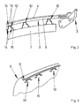
- Figure 1 shows a right portion of a front structure 1 of a motor vehicle in cross-section and a on the front 1 subsequent windscreen 2.
- the front 1 has a pivotally mounted on a hinge 3 hood 4, which in its drawn position a schematic shown internal combustion engine 5 of the motor vehicle covered.
- a fender 6 limited.
- the fender 6 is also at a schematically illustrated body part 7 via a deformation device 8 attached.
- the fender 6 has a water channel 9. A lateral boundary the hood 4 protrudes into the water channel 9.
- the deformation device 8 has a made of sheet metal Deformation member 10 and a made of plastic Filler 11.
- the filler 11 supports the side area of the fender 6 on the body part 7 from.
- the deformation member 10 is attached to the underside of the water channel 9 and supports vertically acting on the fender 6 Forces on the body part 7 from.
- the filler 11 is in a space between the fender 6 and the body part. 7 glued and gives the fender 6 the necessary lateral Rigidity. At the same time, it seals the room of Internal combustion engine 5 against escaping gases and sound.
- FIG. 2 shows the front construction from FIG. 1 in one Sectional view along the line II - II recognize that several individual deformation members 10 between the fender 6 and the hood 4 are attached.
- the deformation members 10 are spaced from each other.
- the deformation members 10 each have a U-shaped section 12.
- the base of the U-shaped Section 12 is at the bottom of the water channel 9 of the Mudguard 6, for example, fixed by spot welding.
- opposite ends of the legs 13 of the U-shaped portion 12 are parallel to the body part 7 guided sections 14 arranged.
- At the parallel to the Body part guided sections 14 close up the body part 7 tapered legs 15 whose free Ends are connected to the body part 7.
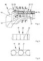
- FIG. 3 shows a perspective sectional view a portion of the fender 6 of Figures 1 and 2 with the deformation members 10 attached thereto Simplification of the drawing is the filler 11 of Figure 1 not shown. It can be seen here that the deformation members 10 exclusively in the area of the water channel 9 of the fender 6 are arranged and thus vertically in the Mudguard dampen 6 initiated forces. Such forces can occur during a head impact of a pedestrian.
- FIG. 4 shows a perspective view of a further embodiment of the front structure 16, in which a deformation device 34 has a filler 17 made of plastic and a gap between a body part 18 and a Fender 19 seen from the engine compartment side closes.
- the filler 17 has a portion 20 with deformation webs 21 and a portion 22 with corrugations 23.
- the Deformation webs 21 are rhombic to each other and vertical arranged inclined and extend horizontally to near to the inside of the fender 19th
- FIG. 5 shows an alternative embodiment of the invention Filler 17 of Figure 4 with the deformation bars 21st having section 20.
- the deformation webs 21 are here arranged vertically and thus formed as buckling bars. at vertical load buckling the deformation webs 21 and therefore allow a yielding of the illustrated in Figure 4 Fender 19 in a head impact of a pedestrian.
- figure Fig. 6 shows a further embodiment of the deformation webs 21 having portion 20 of the filler 17 of FIG 4.
- the deformation webs 21 are arranged here in a circle segment shape.
- the trained as buckling rods or circular segment arranged deformation webs 21 may alternatively or in addition to those shown in Figure 4, diamond-shaped arranged deformation ribs 21 may be provided.
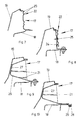
- Figure 7 shows an enlarged sectional view through the filler 17 of Figure 4 with adjacent areas the fender 19 and the body part 18 along the line VII - VII. It can be seen here that the corrugations 23 the wave-shaped portion 22 of the filler 17 in parallel arranged to the fender 19 facing the boundary are. These corrugations 23 allows folding of the filler 17 in a head impact of a pedestrian on the fender 19th
- Figure 8 shows an enlarged sectional view through the front 16 of Figure 4 along the line VIII - VIII in the region of attachment of the fender 19 at the Body part 18.
- the fender 19 is integral with a up to the body part 18 guided deformation member 24th manufactured.
- the deformation member 24 is connected to the body part 18 bolted.
- the filler 17 is above a clip 25th attached to the deformation member 24.
- Figure 9 shows an enlarged sectional view through the filler 17 of Figure 4 along the line IX - IX in the region of its attachment to the body part 18.
- the filler 17 is an arcuate Wall 26 has and the deformation webs 21 within the arcuate Wall 26 are arranged.
- the arched wall 26 is bolted to the body part 18 and is on his the fender 19 laterally supporting area with a Layer of sponge rubber 27 pasted.
- Figure 10 shows enlarged in a sectional view through the front 16 of Figure 4 along the line X - X, that a bracket-shaped holding means 28 integral with the Filler 17 is made.
- the holding means 28 holds one in the front 16 routed harness 29 or Bowden cable.
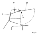
- FIG. 11 shows a cross section through a filling piece 30, which differs from that of FIG. 4 only in that that a chamber 31 for receiving any, not shown components of a panel 32 closed is.
- the diaphragm 32 is connected via a film hinge 33 at the Filler 30 hinged and can be locked on this.
Landscapes
- Engineering & Computer Science (AREA)
- Mechanical Engineering (AREA)
- Chemical & Material Sciences (AREA)
- Combustion & Propulsion (AREA)
- Transportation (AREA)
- Body Structure For Vehicles (AREA)
- Vehicle Body Suspensions (AREA)
- Fluid-Damping Devices (AREA)
- Glass Compositions (AREA)
Abstract
Description
Die Erfindung betrifft einen Vorderbau für ein Kraftfahrzeug mit in der vorgesehenen Fahrtrichtung gesehen vorderen Kotflügeln, mit einem auf Abstand unterhalb der Kotflügel angeordneten Karosserieteil und mit einer zwischen dem Karosserieteil und den Kotflügeln angeordneten Deformationseinrichtung.The invention relates to a front construction for a Motor vehicle with seen in the intended direction of travel front fenders, with one at a distance below the fenders arranged body part and with a between the Body part and the fenders arranged deformation device.
Ein solcher Vorderbau ist beispielsweise aus der DE 29 34 060 A1 bekannt. Die Deformationseinrichtung dieses Vorderbaus hat ein im Querschnitt halbkreisförmig gebogenes Blech zwischen der inneren Kante des Kotflügels und dem darunter liegenden Karosserieteil. Schlägt bei einem Unfall der Kopf eines Fußgängers vertikal auf den Kotflügel, nimmt die Deformationseinrichtung die Stoßenergie auf, wodurch der Kopfaufprall weich erfolgen soll.Such a front end is for example from the DE 29 34 060 A1 known. The deformation device of this front construction has a semi-circular curved in cross-section Sheet metal between the inner edge of the fender and the underneath lying body part. Beats in an accident the Head of a pedestrian vertical to the fender, takes the Deformation the impact energy, causing the Head impact should be soft.
Weiterhin ist aus der EP 1 129 928 B1 ein Vorderbau
bekannt geworden, bei dem die Deformationseinrichtung ebenfalls
ein halbkreisförmiges, den Kotflügel vertikal abstützendes
Blech sowie ein zwischen dem Karosserieteil und einem
Seitenbereich des Kotflügel angeordnetes Abstützteil aufweist.Furthermore, from
Nachteilig bei den bekannten Vorderbauten ist jedoch deren geringe Steifigkeit im Betrieb des Kraftfahrzeuges, welche sich aus der Anforderung an die vertikale Nachgiebigkeit des Kotflügels ergibt. Durch ein Anlehnen an den Kotflügel kann im ungünstigsten Fall der Kotflügel an eine zwischen den Kotflügeln angeordnete Haube anstoßen. Weiterhin ist bei den bekannten Vorderbauten nachteilig, dass Motorgeräusche zwischen dem Kotflügel und dem Karosserieteil nach außen dringen können.A disadvantage of the known front structures, however their low rigidity in the operation of the motor vehicle, which results from the requirement for vertical compliance of the fender results. By leaning against the In the worst case, the fender can be attached to a fender abut the bonnet between the fenders. Farther is disadvantageous in the known front structures that engine noise between the mudguard and the bodywork part can escape to the outside.
Weiterhin ist aus der EP 1 132 263 A1 eine Kotflügelanordnung
für ein Kraftfahrzeug bekannt geworden, bei der
ein mit dem Kotflügel verbundenes Blech mehrere einzelne Laschen
als Deformationsglieder aufweist. Das die Deformationsglieder
aufweisende Blech ist über einen Klebstoffwulst mit
dem Kotflügel verbunden und stützt diesen seitlich ab.
Nachteilig bei der Kotflügelanordnung ist jedoch, dass eine
ungenaue Kleberauftragung zu einer Deformation des Kotflügels
führen kann. Weiterhin dringen bei dieser Kotflügelanordnung
zwischen den Laschen Motorgeräusche nach außen.Furthermore, from
Der Erfindung liegt das Problem zugrunde, einen Vorderbau der eingangs genannten Art so zu gestalten, dass er bei einem Fußgängeraufprall ausreichend nachgiebig gestaltet ist, jedoch im Betrieb eine ausreichende Stabilität aufweist.The invention is based on the problem, a Front of the type mentioned above to be designed so that he designed sufficiently resilient in a pedestrian impact is, but has sufficient stability during operation.
Dieses Problem wird erfindungsgemäß dadurch gelöst, dass die Deformationseinrichtung ein nachgiebiges, aus Kunststoff gefertigtes Füllstück aufweist und dass das Füllstück einen Spalt zwischen dem Karosserieteil und dem Kotflügel verschließt.This problem is solved according to the invention that the deformation device is a resilient, made of plastic manufactured filler and that the filler a gap between the body part and the fender closes.
Durch diese Gestaltung lässt sich die Steifigkeit der Deformationseinrichtung an den einzelnen Stellen des Kotflügels durch eine entsprechende Ausgestaltung des Füllstücks einstellen. Das Füllstück vermag den Kotflügel flächig abstützen und damit im Betrieb des Kraftfahrzeuges auftretende Kräfte aufzunehmen. Eine zusätzlich anzuordnende Verkleidung zur Verhinderung eines Austritts von Motorgeräuschen zwischen dem Kotflügel und dem Karosserieteil ist dank der Erfindung nicht erforderlich, da das Füllstück bei entsprechender Materialwahl schalldämmend gestaltet sein kann und den von den Deformationsgliedern erzeugten Spalt zwischen Karosserieteil und Kotflügel verdeckt.This design allows the rigidity the deformation device at the individual points of the fender by a corresponding embodiment of the filler to adjust. The filler can support the fender flat and thus occurring during operation of the motor vehicle To absorb forces. An additional panel to be arranged to prevent leakage of engine noise between the fender and the body part is thanks to the invention not necessary, because the filler with appropriate choice of material soundproofing and can be designed by the Deformation members generated gap between the body part and fenders concealed.
Im einfachsten Fall weist daher die Deformationseinrichtung ausschließlich das Füllstück auf. Zur weiteren Vereinfachung der Einstellung der vorgesehenen Steifigkeit der Deformationseinrichtung trägt es gemäß einer vorteilhaften Weiterbildung der Erfindung bei, wenn die Deformationseinrichtung aus Blech gefertigte Deformationsglieder aufweist und wenn das Füllstück zwischen den Deformationsgliedern angeordnet ist. Durch diese Gestaltung lassen sich zusätzlich zu dem Füllstück die aus Blech gefertigten Deformationsglieder an vorgesehenen Stellen anordnen, an denen eine ausschließliche Abstützung durch das Füllstück nur unzureichend ist.In the simplest case, therefore, the deformation device only the filler on. To further Simplifying the setting of the intended stiffness the deformation device carries it according to an advantageous Further development of the invention, when the deformation device made of sheet metal deformation members and if the filler between the deformation members is arranged. Through this design can be in addition to the filler, the deformation members made of sheet metal order at designated locations where one exclusive support by the filler only inadequate is.
Zur weiteren Verbesserungen der Schalldämmung des Bereichs zwischen dem Kotflügel und dem Karosserieteil des erfindungsgemäßen Vorderbaus trägt es bei, wenn sich das Füllstück in Fahrtrichtung gesehen über die gesamte Länge des Kotflügels erstreckt.To further improve the sound insulation of the Area between the fender and the bodywork part of the Front construction according to the invention contributes when the Filler seen in the direction of travel over the entire length of the Fender extends.
Die Montage des erfindungsgemäßen Vorderbaus erfordert einen besonders geringen Aufwand, wenn das Füllstück einstückig gefertigt ist.The assembly of the front building according to the invention requires a particularly low cost when the filler is made in one piece.
Das Füllstück vermag gemäß einer vorteilhaften Weiterbildung der Erfindung eine Übertragung von Schall sehr stark zu dämmen, wenn das Füllstück an seiner an dem Kotflügel anliegenden Seite eine Schicht Moosgummi aufweist.The filler can according to an advantageous development the invention a transmission of sound very strongly dam when the filler at its on the fender adjacent side has a layer of sponge rubber.
Zur weiteren Vereinfachung der Montage des erfindungsgemäßen Vorderbaus trägt es bei, wenn das Füllstück mit dem Karosserieteil und/oder dem Kotflügel verklebt ist. To further simplify the assembly of the invention Front construction contributes to it, if the filler with glued to the body part and / or the fender.
Ein Anstoßen der Kotflügel an eine zwischen den Kotflügeln angeordnete Haube durch ein Anlehnen oder eine Wäsche des Kraftfahrzeugs lässt sich gemäß einer anderen vorteilhaften Weiterbildung der Erfindung einfach vermeiden, wenn das Füllstück den Kotflügel seitlich abstützt. Damit nimmt das Füllstück seitlich in den Kotflügel eingeleitete Kräfte auf. Hierzu ist das Füllstück zumindest teilweise zwischen dem Seitenbereich der Kotflügel und dem Karosserieteil anzuordnen.An abutment of the fenders to one between the Fenders arranged hood by leaning or a Laundry of the motor vehicle can be according to another advantageous Simply avoid development of the invention when the filler laterally supports the fender. In order to takes the filler introduced laterally into the fender Forces up. For this purpose, the filler is at least partially between the side area of the fenders and the body part to arrange.
Ein Austreten von Motorraumgasen zwischen dem Kotflügel und dem Karosserieteil lässt sich gemäß einer anderen vorteilhaften Weiterbildung der Erfindung einfach vermeiden, wenn das Füllstück den Raum zwischen dem Kotflügel und dem Karosserieteil gasdicht verschließt.A leakage of engine compartment gases between the fender and the body part can be according to another simply avoid an advantageous development of the invention if the filler the space between the fender and the Closes body part gas-tight.
Die Festlegung der Stabilität des Füllstücks bei einem Kopfaufprall auf den Kotflügel gestaltet sich gemäß einer anderen vorteilhaften Weiterbildung der Erfindung besonders einfach, wenn das Füllstück Deformationsstege aufweist. Die Deformationsstege können beispielsweise waben- oder kreissegmentförmig oder als vertikale Knickstäbe ausgebildet sein.Determining the stability of the filler at A head impact on the fender is designed according to a another advantageous embodiment of the invention particularly easy if the filler has deformation bars. The deformation bars can, for example, honeycomb or circular segment or formed as a vertical buckling bars be.
Die Deformationsstege lassen sich gemäß einer anderen vorteilhaften Weiterbildung der Erfindung mit sehr großen Abmessungen versehen und bis in den Seitenbereich des Kotflügels führen, wenn ein die Deformationsstege aufweisender Abschnitt des Füllstücks zwischen Verschraubungsstellen mit dem Kotflügel und/oder dem Karosserieteil angeordnet ist.The Deformationsstege can be according to another advantageous development of the invention with very large Dimensions provided and up in the side area of the fender lead, if a section having the deformation webs of the filler between bolting with the Fender and / or the body part is arranged.
Das Füllstück weist gemäß einer anderen vorteilhaften Weiterbildung der Erfindung in horizontaler Richtung eine hohe Stabilität und in vertikaler Richtung eine nahezu beliebig einstellbare Stabilität auf, wenn die Deformationsstege vertikal geneigt von dem Kotflügel zu dem Karosserieteil und horizontal bis zu dem Seitenbereich des Kotflügels geführt sind.The filler has according to another advantageous Development of the invention in the horizontal direction a high stability and in the vertical direction a nearly arbitrary adjustable stability on when the deformation bars vertically inclined from the fender to the body part and guided horizontally up to the side area of the fender are.
Das Füllstück lässt sich gemäß einer anderen vorteilhaften Weiterbildung der Erfindung zumindest in Teilbereichen mit einer hohen Elastizität versehen, wenn das Füllstück eine wellenförmige Struktur hat, wobei Wellungen des Füllstücks parallel zu der an den Kotflügel angrenzenden Kante angeordnet sind.The filler can be according to another advantageous Development of the invention, at least in some areas provided with a high elasticity when the filler has a wavy structure, with corrugations of the Filler parallel to the edge adjacent to the fender edge are arranged.
Die Montage und Demontage des Kotflügels gestalten sich konstruktiv besonders einfach, wenn das Füllstück mit dem Karosserieteil und/oder dem Kotflügel verschraubt ist.Design the assembly and disassembly of the fender structurally particularly simple if the filler with bolted to the body part and / or the fender.
Zur weiteren Vereinfachung der Montage des erfindungsgemäßen Vorderbaus trägt es bei, wenn das Füllstück zur Halterung von in einem Motorraum zu verlegenden Bauteilen vorgesehene Haltemittel hat. Im einfachsten Fall sind die Haltemittel als Klammern ausgebildet. In diese Klammern lassen sich beispielsweise Kabelbäume und Bowdenzüge verrasten.To further simplify the assembly of the invention Front construction contributes, if the filler to Mounting of components to be laid in an engine compartment has provided retaining means. In the simplest case, the Holding means formed as brackets. Leave in these brackets For example, harnesses and Bowden cables lock.
Verschiedene Bauteile lassen sich im erfindungsgemäßen Vorderbau einfach unterbringen, wenn das Füllstück eine von einer Blende verdeckte Kammer aufweist. Durch diese Gestaltung lassen sich beispielsweise die Bowdenzüge oder Kabelbäume in dem Füllstück ablegen.Various components can be in the invention Easy to accommodate the front if the filler is a having a hood concealed chamber. Through this design can be, for example, the Bowden cables or wiring harnesses place in the filler.
Die Montage des Füllstücks erfordert gemäß einer anderen vorteilhaften Weiterbildung der Erfindung einen besonders geringen Aufwand, wenn die Blende über ein Filmscharnier mit einer seitlichen Begrenzung der Kammer verbunden ist.The fitting of the filler requires according to a another advantageous embodiment of the invention a particular little effort when the bezel over a film hinge connected to a lateral boundary of the chamber is.
Die Steifigkeit der Deformationseinrichtung lässt sich gemäß einer anderen vorteilhaften Weiterbildung der Erfindung einfach einstellen, wenn die Deformationsglieder einen U-förmig gebogenen Abschnitt aufweisen, mit ihrer Basis an dem Kotflügel befestigt sind und mit Schenkeln auf das Karosserieteil zuweisen.The stiffness of the deformation device leaves according to another advantageous embodiment of the invention just adjust when the deformation links a U-shaped bent section, with its base attached to the fender and with legs on the body part to assign.
Eine plastische Verformung der Deformationseinrichtung lässt sich gemäß einer anderen vorteilhaften Weiterbildung der Erfindung einfach vermeiden, wenn sich an den der Basis abgewandten Enden der Schenkel des U-förmigen Abschnitts der Deformationsglieder parallel zu dem Karosserieteil geführte Abschnitte anschließen und wenn sich an den parallel geführten Abschnitten auf das Karosserieteil zuweisende Schenkel anschließen. Die parallel zu dem Kotflügel geführten Abschnitte ermöglichen eine geringfügige elastische Nachgiebigkeit der Deformationsglieder.A plastic deformation of the deformation device can be according to another advantageous development The invention simply avoid when the s.den Base remote ends of the legs of the U-shaped section the deformation members parallel to the body part connect led sections and when connected to the parallel guided sections attributed to the body part Connect leg. The run parallel to the fender Sections allow a slight elastic Compliance of the deformation members.
Bei einem Kopfaufprall auftretende Kräfte lassen sich gemäß einer anderen vorteilhaften Weiterbildung der Erfindung unbeeinflusst von der seitlichen Abstützung des Kotflügels dämpfen, wenn die Deformationsglieder den Kotflügel ausschließlich vertikal abstützen. Das den Kotflügel seitlich abstützende Füllstück beeinflusst nicht die vertikale Nachgiebigkeit des Kotflügels.Leave forces occurring during a head impact according to another advantageous embodiment of the invention unaffected by the lateral support of the fender dampen when the deformation links the fender support only vertically. That the fender sideways supporting filler does not affect the vertical compliance of the fender.
Die Deformationsglieder lassen sich gemäß einer anderen vorteilhaften Weiterbildung der Erfindung besonders kostengünstig, beispielsweise durch Punktschweißen an dem Kotflügel montieren, wenn die Deformationsglieder an einem, der Haube zugewandten Begrenzung der Kotflügel angeordneten Wasserkanal befestigt sind. Ein solcher Wasserkanal wird von der Haube verdeckt und ist damit im montierten Zustand des Kraftfahrzeuges nicht zu sehen.The deformation members can be according to another advantageous embodiment of the invention particularly cost, for example, by spot welding on the Mount mudguard when the deformation links are at one, arranged the hood facing the boundary of the fender Water channel are attached. Such a water channel is from the hood is concealed and is thus in the assembled state of Motor vehicle not to see.
Der erfindungsgemäße Vorderbau gestaltet sich konstruktiv besonders einfach, wenn die Deformationsglieder als einzelne, an dem Kotflügel und dem Karosserieteil befestigte Baueile ausgebildet sind. Weiterhin ermöglicht die Fertigung der Deformationsglieder als einzelne Bauteile eine besonders einfache Festlegung der Stabilität der Deformationseinrichtung.The front of the invention designed constructively especially simple when the deformation members as individual, attached to the fender and the body part Building parts are formed. Furthermore, the production allows the deformation members as individual components a particular easy determination of the stability of the deformation device.
Die Erfindung lässt verschiedene Ausführungsformen zu. Zur weiteren Verdeutlichung ihres Grundprinzips sind mehrere davon in der Zeichnung dargestellt und werden nachfolgend beschrieben. Die Zeichnung zeigt in
- Fig. 1
- einen rechten Teilbereich eines erfindungsgemäßen Vorderbaus eines Kraftfahrzeuges im Querschnitt,
- Fig. 2
- eine Schnittdarstellung durch den erfindungsgemäßen
Vorderbau aus
Figur 1 entlang der Linie II - II, - Fig. 3
- eine perspektivische Darstellung eines Kotflügels des erfindungsgemäßen Vorderbaus vor der Montage,
- Fig. 4
- eine perspektivische Darstellung einer weiteren Ausführungsform des erfindungsgemäßen Vorderbaus,
- Fig. 5
- eine alternative Ausführungsform eines
Füllstücks aus
Figur 4, - Fig. 6
- eine alternative Ausführungsform des
Füllstücks aus
Figur 4, - Fig. 7
- eine vergrößerte Schnittdarstellung durch
den Vorderbau aus
Figur 4 entlang der Linie VII - VII, - Fig. 8
- eine vergrößerte Schnittdarstellung durch
den Vorderbau aus
Figur 4 entlang der Linie VIII - VIII, - Fig. 9
- eine vergrößerte Schnittdarstellung durch
den
Vorderbau aus Figur 4 entlang der Linie IX - IX, - Fig. 10
- eine vergrößerte Schnittdarstellung durch
den
Vorderbau aus Figur 4 entlang der Linie X - X, - Fig. 11
- einen Querschnitt durch eine weitere Ausführungsform des Füllstücks aus Figur 4.
- Fig. 1
- a right portion of a front structure according to the invention of a motor vehicle in cross section,
- Fig. 2
- 3 is a sectional view through the front construction according to the invention from FIG. 1 along the line II-II, FIG.
- Fig. 3
- a perspective view of a fender of the front structure according to the invention prior to assembly,
- Fig. 4
- a perspective view of another embodiment of the front building according to the invention,
- Fig. 5
- an alternative embodiment of a filling piece from FIG. 4,
- Fig. 6
- an alternative embodiment of the filler of Figure 4,
- Fig. 7
- 2 is an enlarged sectional view through the front structure of FIG. 4 along the line VII-VII, FIG.
- Fig. 8
- an enlarged sectional view through the front of Figure 4 along the line VIII - VIII,
- Fig. 9
- an enlarged sectional view through the front of Figure 4 along the line IX - IX,
- Fig. 10
- an enlarged sectional view through the front of Figure 4 along the line X - X,
- Fig. 11
- a cross section through a further embodiment of the filler of Figure 4.
Figur 1 zeigt einen rechten Teilbereich eines Vorderbaus
1 eines Kraftfahrzeugs im Querschnitt und eine sich
an den Vorderbau 1 anschließende Frontscheibe 2. Der Vorderbau
1 hat eine an einem Scharnier 3 schwenkbar gelagerte Haube
4, welche in ihrer eingezeichneten Lage eine schematisch
dargestellte Brennkraftmaschine 5 des Kraftfahrzeuges überdeckt.
Seitlich wird der Vorderbau 1 von einem Kotflügel 6
begrenzt. Der Kotflügel 6 ist an einem ebenfalls schematisch
dargestellten Karosserieteil 7 über eine Deformationseinrichtung
8 befestigt. An seiner an die Haube 4 angrenzenden Kante
hat der Kotflügel 6 einen Wasserkanal 9. Eine seitliche Begrenzung
der Haube 4 ragt in den Wasserkanal 9 hinein.Figure 1 shows a right portion of a
Die Deformationseinrichtung 8 hat ein aus Blech gefertigtes
Deformationsglied 10 und ein aus Kunststoff gefertigtes
Füllstück 11. Das Füllstück 11 stützt den Seitenbereich
des Kotflügels 6 an dem Karosserieteil 7 ab. Das Deformationsglied
10 ist an der Unterseite des Wasserkanals 9 befestigt
und stützt vertikal auf den Kotflügel 6 einwirkende
Kräfte an dem Karosserieteil 7 ab. Das Füllstück 11 ist in
einem Raum zwischen dem Kotflügel 6 und dem Karosserieteil 7
eingeklebt und verleiht dem Kotflügel 6 die notwendige seitliche
Steifigkeit. Gleichzeitig dichtet es den Raum der
Brennkraftmaschine 5 gegen austretende Gase und Schall ab. The
Figur 2 zeigt den Vorderbau aus Figur 1 in einer
Schnittdarstellung entlang der Linie II - II. Hierbei ist zu
erkennen, dass mehrere einzelne Deformationsglieder 10 zwischen
dem Kotflügel 6 und der Haube 4 befestigt sind. Die Deformationsglieder
10 sind voneinander beabstandet. Zur Vereinfachung
der Zeichnung ist das Füllstück 11 aus Figur 1
nicht dargestellt. Die Deformationsglieder 10 weisen jeweils
einen U-förmigen Abschnitt 12 auf. Die Basis des U-förmigen
Abschnitts 12 ist an der Unterseite des Wasserkanals 9 des
Kotflügels 6 beispielsweise durch Punktschweißung befestigt.
An den dem Kotflügel 6 abgewandten Enden der Schenkel 13 des
U-förmigen Abschnitts 12 sind parallel zu dem Karosserieteil
7 geführte Abschnitte 14 angeordnet. An den parallel zu dem
Karosserieteil geführten Abschnitten 14 schließen sich auf
das Karosserieteil 7 zulaufende Schenkel 15 an, deren freie
Enden mit dem Karosserieteil 7 verbunden sind.FIG. 2 shows the front construction from FIG. 1 in one
Sectional view along the line II - II
recognize that several
Figur 3 zeigt in einer perspektivischen Schnittdarstellung
einen Teilbereich des Kotflügels 6 aus den Figuren 1
und 2 mit den daran befestigten Deformationsgliedern 10. Zur
Vereinfachung der Zeichnung ist das Füllstück 11 aus Figur 1
nicht dargestellt. Hierbei ist zu erkennen, dass die Deformationsglieder
10 ausschließlich im Bereich des Wasserkanals 9
des Kotflügels 6 angeordnet sind und damit vertikal in den
Kotflügel 6 eingeleitete Kräfte dämpfen. Solche Kräfte können
bei einem Kopfaufprall eines Fußgängers auftreten.FIG. 3 shows a perspective sectional view
a portion of the
Figur 4 zeigt perspektivisch eine weitere Ausführungsform
des Vorderbaus 16, bei dem eine Deformationseinrichtung
34 ein Füllstück 17 aus Kunststoff aufweist
und einen Spalt zwischen einem Karosserieteil 18 und einem
Kotflügel 19 von der Motorraumseite aus gesehen verschließt.
Das Füllstück 17 weist einen Abschnitt 20 mit Deformationsstegen
21 und einen Abschnitt 22 mit Wellungen 23 auf. Die
Deformationsstege 21 sind rautenförmig zueinander und vertikal
geneigt angeordnet und erstrecken sich horizontal bis nahe
an die Innenseite des Kotflügels 19. FIG. 4 shows a perspective view of a further embodiment
of the
Figur 5 zeigt eine alternative Ausführungsform des
Füllstücks 17 aus Figur 4 mit dem die Deformationsstege 21
aufweisenden Abschnitt 20. Die Deformationsstege 21 sind hier
vertikal angeordnet und damit als Knickstäbe ausgebildet. Bei
senkrechter Belastung knicken die Deformationsstege 21 und
ermöglichen daher ein Nachgeben des in Figur 4 dargestellten
Kotflügels 19 bei einem Kopfaufprall eines Fußgängers. Figur
6 zeigt eine weitere Ausführungsform des die Deformationsstege
21 aufweisenden Abschnitts 20 des Füllstücks 17 aus Figur
4. Die Deformationsstege 21 sind hier kreissegmentförmig angeordnet.
Die als Knickstäbe ausgebildeten oder kreissegmentförmig
angeordneten Deformationsstege 21 können alternativ
oder zusätzlich zu den in Figur 4 dargestellten, rautenförmig
angeordneten Deformationsstegen 21 vorgesehen sein.FIG. 5 shows an alternative embodiment of the
Figur 7 zeigt vergrößert eine Schnittdarstellung
durch das Füllstück 17 aus Figur 4 mit angrenzenden Bereichen
des Kotflügels 19 und des Karosserieteils 18 entlang der Linie
VII - VII. Hierbei ist zu erkennen, dass die Wellungen 23
des wellenförmigen Abschnitts 22 des Füllstücks 17 parallel
zu der dem Kotflügel 19 zugewandten Begrenzung angeordnet
sind. Diese Wellungen 23 ermöglicht ein Falten des Füllstücks
17 bei einem Kopfaufprall eines Fußgängers auf den Kotflügel
19.Figure 7 shows an enlarged sectional view
through the
Figur 8 zeigt vergrößert eine Schnittdarstellung
durch den Vorderbau 16 aus Figur 4 entlang der Linie VIII -
VIII im Bereich einer Befestigung des Kotflügels 19 an dem
Karosserieteil 18. Der Kotflügel 19 ist einstückig mit einem
bis zu dem Karosserieteil 18 geführten Deformationsglied 24
gefertigt. Das Deformationsglied 24 ist mit dem Karosserieteil
18 verschraubt. Das Füllstück 17 ist über einen Klipp 25
an dem Deformationsglied 24 befestigt.Figure 8 shows an enlarged sectional view
through the
Figur 9 zeigt vergrößert eine Schnittdarstellung
durch das Füllstück 17 aus Figur 4 entlang der Linie IX - IX
im Bereich seiner Befestigung an dem Karosserieteil 18. Hierbei
ist zu erkennen, dass das Füllstück 17 eine bogenförmige
Wandung 26 hat und die Deformationsstege 21 innerhalb der bogenförmigen
Wandung 26 angeordnet sind. Die bogenförmige Wandung
26 ist mit dem Karosserieteil 18 verschraubt und ist an
seinem den Kotflügel 19 seitlich abstützenden Bereich mit einer
Schicht Moosgummi 27 beklebt.Figure 9 shows an enlarged sectional view
through the
Figur 10 zeigt vergrößert in einer Schnittdarstellung
durch den Vorderbau 16 aus Figur 4 entlang der Linie X -
X, dass ein klammerförmiges Haltemittel 28 einstückig mit dem
Füllstück 17 gefertigt ist. Das Haltemittel 28 haltert einen
in dem Vorderbau 16 verlegten Kabelbaum 29 oder Bowdenzug.Figure 10 shows enlarged in a sectional view
through the
Figur 11 zeigt einen Querschnitt durch ein Füllstück
30, welches sich von dem aus Figur 4 nur dadurch unterscheidet,
dass eine Kammer 31 zur Aufnahme von beliebigen,
nicht dargestellten Bauteilen von einer Blende 32 verschließbar
ist. Die Blende 32 ist über ein Filmscharnier 33 an dem
Füllstück 30 angelenkt und lässt sich an diesem verrasten. FIG. 11 shows a cross section through a filling
- 11
- Vorderbaufront end
- 22
- Frontscheibewindscreen
- 33
- Scharnierhinge
- 44
- HaubeHood
- 55
- BrennkraftmaschineInternal combustion engine
- 66
- Kotflügelfender
- 77
- KrosserieteilKrosserieteil
- 88th
- Deformationseinrichtungdeformation device
- 99
- Wasserkanalwater channel
- 1010
- Deformationsglieddeformation member
- 1111
- Füllstückfilling
- 1212
- Abschnittsection
- 1313
- Schenkelleg
- 1414
- Abschnittsection
- 1515
- Schenkelleg
- 1616
- Vorderbaufront end
- 1717
- Füllstückfilling
- 1818
- KrosserieteilKrosserieteil
- 1919
- Kotflügelfender
- 2020
- Abschnittsection
- 2121
- Deformationsstegdeformation bridge
- 2222
- Abschnittsection
- 2323
- Wellungcurl
- 2424
- Deformationsglieddeformation member
- 2525
- Klippclip
- 2626
- Wandungwall
- 2727
- Moosgummi foam rubber
- 2828
- Haltemittelholding means
- 2929
- Kabelbaumharness
- 3030
- Füllstückfilling
- 3131
- Kammerchamber
- 3232
- Blendecover
- 3333
- Filmscharnierfilm hinge
- 3434
- Deformationseinrichtungdeformation device
Claims (21)
Applications Claiming Priority (2)
| Application Number | Priority Date | Filing Date | Title |
|---|---|---|---|
| DE102004011333 | 2004-03-09 | ||
| DE102004011333A DE102004011333A1 (en) | 2004-03-09 | 2004-03-09 | Front end for a motor vehicle |
Publications (2)
| Publication Number | Publication Date |
|---|---|
| EP1574423A1 true EP1574423A1 (en) | 2005-09-14 |
| EP1574423B1 EP1574423B1 (en) | 2008-03-26 |
Family
ID=34813623
Family Applications (1)
| Application Number | Title | Priority Date | Filing Date |
|---|---|---|---|
| EP05004096A Expired - Lifetime EP1574423B1 (en) | 2004-03-09 | 2005-02-25 | Front structure for a motor vehicle |
Country Status (3)
| Country | Link |
|---|---|
| EP (1) | EP1574423B1 (en) |
| AT (1) | ATE390342T1 (en) |
| DE (2) | DE102004011333A1 (en) |
Cited By (3)
| Publication number | Priority date | Publication date | Assignee | Title |
|---|---|---|---|---|
| WO2007003440A1 (en) * | 2005-07-06 | 2007-01-11 | Peguform Gmbh | Structure of the front part of a motor vehicle |
| FR2899554A1 (en) * | 2006-04-11 | 2007-10-12 | Peugeot Citroen Automobiles Sa | FRONT BLOCK OF A MOTOR VEHICLE AND SUPPORT PART OF A SIDE WING BEFORE SUCH A VEHICLE |
| FR2911106A1 (en) * | 2007-01-09 | 2008-07-11 | Renault Sas | Support for fixing body element i.e. front wing, of motor vehicle, has connection surface supported against complementary surface of body element to form sliding connection between support and body element |
Families Citing this family (1)
| Publication number | Priority date | Publication date | Assignee | Title |
|---|---|---|---|---|
| DE102010016213B4 (en) | 2010-03-30 | 2024-09-05 | Dr. Ing. H.C. F. Porsche Aktiengesellschaft | Motor vehicle |
Citations (7)
| Publication number | Priority date | Publication date | Assignee | Title |
|---|---|---|---|---|
| EP1090818A2 (en) * | 1999-10-09 | 2001-04-11 | Volkswagen Aktiengesellschaft | Motor vehicle with pedestrian friendly front end |
| EP1106448A2 (en) * | 1999-12-10 | 2001-06-13 | Volkswagen Aktiengesellschaft | Vehicle lateral steel sheet with an outer edge deformable under impact |
| JP2001199366A (en) * | 2000-12-20 | 2001-07-24 | Toyota Motor Corp | Car fender structure |
| GB2362615A (en) * | 2000-05-23 | 2001-11-28 | Corus Uk Ltd | A collapsible fixing for attaching a vehicle fender, wing or bonnet to a vehicle body |
| US20020063443A1 (en) * | 2000-11-30 | 2002-05-30 | Wan-Young Lee | Fender panel impact absorption structure of vehicle having walker protection function |
| DE10233474A1 (en) * | 2002-07-24 | 2004-02-26 | Volkswagen Ag | Wing for motor vehicles has C-form deformation element with one or more extensions of upper member pointing downwards and rigidly connected to lower member of C-form deformation element |
| DE10309958A1 (en) * | 2003-03-07 | 2004-09-23 | Dr.Ing.H.C. F. Porsche Ag | Automobile with pedestrian protection device using deformation element bridged by releasable blocking device supporting front hood and/or adjacent body component during normal driving |
Family Cites Families (8)
| Publication number | Priority date | Publication date | Assignee | Title |
|---|---|---|---|---|
| DE2934060A1 (en) * | 1979-08-23 | 1981-03-26 | Daimler-Benz Aktiengesellschaft, 70567 Stuttgart | MOTOR VEHICLE, ESPECIALLY PERSONAL VEHICLES, WITH FLEXIBLE BODY FRONTS |
| DE10009364A1 (en) * | 2000-02-29 | 2001-08-30 | Volkswagen Ag | Fender assembly for a motor vehicle |
| DE10009363A1 (en) * | 2000-02-29 | 2001-08-30 | Volkswagen Ag | Wing arrangement for motor vehicles has reinforcing part along upper inside edge, forming hollow profile, to reduce/prevent injuries to pedestrians during collisions |
| DE10102187A1 (en) * | 2001-01-16 | 2002-08-01 | Volkswagen Ag | Impact damping mudguard for a vehicle comprises a support element which is made of a hard, almost inflexible material, and is divided by a fold line into two sections forming an obtuse angle |
| JP4762438B2 (en) * | 2001-05-18 | 2011-08-31 | 富士重工業株式会社 | Front body structure of the vehicle |
| DE10206768B4 (en) * | 2002-02-19 | 2005-11-17 | Daimlerchrysler Ag | Mudguard arrangement for a motor vehicle |
| US6846026B2 (en) * | 2002-02-28 | 2005-01-25 | Honda Giken Kogyo Kabushiki Kaisha | Vehicle pedestrian safety bumper system |
| DE10244455A1 (en) * | 2002-09-24 | 2004-05-13 | Volkswagen Ag | Fender structure on motor vehicles |
-
2004
- 2004-03-09 DE DE102004011333A patent/DE102004011333A1/en not_active Withdrawn
-
2005
- 2005-02-25 DE DE502005003410T patent/DE502005003410D1/en not_active Expired - Lifetime
- 2005-02-25 EP EP05004096A patent/EP1574423B1/en not_active Expired - Lifetime
- 2005-02-25 AT AT05004096T patent/ATE390342T1/en not_active IP Right Cessation
Patent Citations (7)
| Publication number | Priority date | Publication date | Assignee | Title |
|---|---|---|---|---|
| EP1090818A2 (en) * | 1999-10-09 | 2001-04-11 | Volkswagen Aktiengesellschaft | Motor vehicle with pedestrian friendly front end |
| EP1106448A2 (en) * | 1999-12-10 | 2001-06-13 | Volkswagen Aktiengesellschaft | Vehicle lateral steel sheet with an outer edge deformable under impact |
| GB2362615A (en) * | 2000-05-23 | 2001-11-28 | Corus Uk Ltd | A collapsible fixing for attaching a vehicle fender, wing or bonnet to a vehicle body |
| US20020063443A1 (en) * | 2000-11-30 | 2002-05-30 | Wan-Young Lee | Fender panel impact absorption structure of vehicle having walker protection function |
| JP2001199366A (en) * | 2000-12-20 | 2001-07-24 | Toyota Motor Corp | Car fender structure |
| DE10233474A1 (en) * | 2002-07-24 | 2004-02-26 | Volkswagen Ag | Wing for motor vehicles has C-form deformation element with one or more extensions of upper member pointing downwards and rigidly connected to lower member of C-form deformation element |
| DE10309958A1 (en) * | 2003-03-07 | 2004-09-23 | Dr.Ing.H.C. F. Porsche Ag | Automobile with pedestrian protection device using deformation element bridged by releasable blocking device supporting front hood and/or adjacent body component during normal driving |
Non-Patent Citations (1)
| Title |
|---|
| PATENT ABSTRACTS OF JAPAN vol. 2000, no. 24 11 May 2001 (2001-05-11) * |
Cited By (6)
| Publication number | Priority date | Publication date | Assignee | Title |
|---|---|---|---|---|
| WO2007003440A1 (en) * | 2005-07-06 | 2007-01-11 | Peguform Gmbh | Structure of the front part of a motor vehicle |
| DE102005031843C5 (en) * | 2005-07-06 | 2009-05-20 | Peguform Gmbh | Front end structure of a motor vehicle |
| US7828374B2 (en) | 2005-07-06 | 2010-11-09 | Peguform Gmbh | Structure of the front part of a motor vehicle |
| FR2899554A1 (en) * | 2006-04-11 | 2007-10-12 | Peugeot Citroen Automobiles Sa | FRONT BLOCK OF A MOTOR VEHICLE AND SUPPORT PART OF A SIDE WING BEFORE SUCH A VEHICLE |
| WO2007116145A1 (en) | 2006-04-11 | 2007-10-18 | Peugeot Citroen Automobiles Sa | Front end of a motor vehicle, and part for supporting a front side wing of such a vehicle |
| FR2911106A1 (en) * | 2007-01-09 | 2008-07-11 | Renault Sas | Support for fixing body element i.e. front wing, of motor vehicle, has connection surface supported against complementary surface of body element to form sliding connection between support and body element |
Also Published As
| Publication number | Publication date |
|---|---|
| ATE390342T1 (en) | 2008-04-15 |
| DE502005003410D1 (en) | 2008-05-08 |
| EP1574423B1 (en) | 2008-03-26 |
| DE102004011333A1 (en) | 2005-09-22 |
Similar Documents
| Publication | Publication Date | Title |
|---|---|---|
| DE69808340T2 (en) | Motor vehicle and base plate provided for protecting the engine block | |
| DE102009057778B4 (en) | Vehicle Auspuffendanordnung | |
| DE102007003535B4 (en) | Roof side trim perimeter structure of a motor vehicle | |
| DE69925954T2 (en) | Continuously flexible, energy absorbing, swept arch for interior trim | |
| DE102016113169B4 (en) | Motor vehicle with an instrument panel | |
| DE102008049762A1 (en) | Front structure for motor vehicle, has front frame that is arranged before front wall and comprising cross beam, where cross beam comprises reinforcement element that is made of plastic | |
| EP3873758B1 (en) | Arrangement of an air guiding element made of foam on a cooler element, and cooler element and air guiding element made of foam | |
| DE102004007571A1 (en) | Front section for a vehicle, in particular, a motor vehicle comprises at least one pedestrian protection beam which is produced as a single-piece plastic component | |
| DE102016010366B4 (en) | VEHICLE FRONT STRUCTURE | |
| DE10329906B4 (en) | Bonnet system | |
| DE10149116C1 (en) | Large bodywork element, in particular engine or front hood of a motor vehicle | |
| DE4309100A1 (en) | Side cover for commercial vehicles | |
| EP1574423B1 (en) | Front structure for a motor vehicle | |
| DE2449574C3 (en) | Soundproofing device for the internal combustion engine of motor vehicles | |
| DE10347830B4 (en) | Arrangement of a front flap on a vehicle | |
| DE102009039805A1 (en) | Front structure for use with body of car, has carrier part connecting support with bumper and adjacent components of body of vehicle, where bumper, support and carrier part are formed as pre-mountable structural unit | |
| EP1058632B1 (en) | Motor vehicle engine area downward protection base plate | |
| DE102014101452A1 (en) | Airbag device for a vehicle | |
| EP1600338A1 (en) | Vehicle with deformable energy absorbing member | |
| DE102020117209A1 (en) | Method for manufacturing a body for a motor vehicle and a body for a motor vehicle | |
| EP0875425A2 (en) | Cover for a passenger airbag module | |
| DE2432238C3 (en) | Carrier arrangement on a body, in particular for passenger cars | |
| DE102022106128A1 (en) | vehicle rear structure | |
| DE10232321A1 (en) | Bumper mounting for motor vehicles consists of profiled metal strut with integrated plastic part having external impact surface connected to rail, for energy absorption | |
| DE102004001702B4 (en) | Front end for a motor vehicle |
Legal Events
| Date | Code | Title | Description |
|---|---|---|---|
| PUAI | Public reference made under article 153(3) epc to a published international application that has entered the european phase |
Free format text: ORIGINAL CODE: 0009012 |
|
| AK | Designated contracting states |
Kind code of ref document: A1 Designated state(s): AT BE BG CH CY CZ DE DK EE ES FI FR GB GR HU IE IS IT LI LT LU MC NL PL PT RO SE SI SK TR |
|
| AX | Request for extension of the european patent |
Extension state: AL BA HR LV MK YU |
|
| 17P | Request for examination filed |
Effective date: 20051110 |
|
| AKX | Designation fees paid |
Designated state(s): AT BE BG CH CY CZ DE DK EE ES FI FR GB GR HU IE IS IT LI LT LU MC NL PL PT RO SE SI SK TR |
|
| 17Q | First examination report despatched |
Effective date: 20070208 |
|
| GRAP | Despatch of communication of intention to grant a patent |
Free format text: ORIGINAL CODE: EPIDOSNIGR1 |
|
| GRAS | Grant fee paid |
Free format text: ORIGINAL CODE: EPIDOSNIGR3 |
|
| GRAA | (expected) grant |
Free format text: ORIGINAL CODE: 0009210 |
|
| AK | Designated contracting states |
Kind code of ref document: B1 Designated state(s): AT BE BG CH CY CZ DE DK EE ES FI FR GB GR HU IE IS IT LI LT LU MC NL PL PT RO SE SI SK TR |
|
| REG | Reference to a national code |
Ref country code: GB Ref legal event code: FG4D Free format text: NOT ENGLISH |
|
| REG | Reference to a national code |
Ref country code: CH Ref legal event code: EP Ref country code: IE Ref legal event code: FG4D Free format text: LANGUAGE OF EP DOCUMENT: GERMAN |
|
| REF | Corresponds to: |
Ref document number: 502005003410 Country of ref document: DE Date of ref document: 20080508 Kind code of ref document: P |
|
| PG25 | Lapsed in a contracting state [announced via postgrant information from national office to epo] |
Ref country code: FI Free format text: LAPSE BECAUSE OF FAILURE TO SUBMIT A TRANSLATION OF THE DESCRIPTION OR TO PAY THE FEE WITHIN THE PRESCRIBED TIME-LIMIT Effective date: 20080326 |
|
| NLV1 | Nl: lapsed or annulled due to failure to fulfill the requirements of art. 29p and 29m of the patents act | ||
| PG25 | Lapsed in a contracting state [announced via postgrant information from national office to epo] |
Ref country code: SI Free format text: LAPSE BECAUSE OF FAILURE TO SUBMIT A TRANSLATION OF THE DESCRIPTION OR TO PAY THE FEE WITHIN THE PRESCRIBED TIME-LIMIT Effective date: 20080326 Ref country code: PL Free format text: LAPSE BECAUSE OF FAILURE TO SUBMIT A TRANSLATION OF THE DESCRIPTION OR TO PAY THE FEE WITHIN THE PRESCRIBED TIME-LIMIT Effective date: 20080326 |
|
| REG | Reference to a national code |
Ref country code: IE Ref legal event code: FD4D |
|
| PG25 | Lapsed in a contracting state [announced via postgrant information from national office to epo] |
Ref country code: SE Free format text: LAPSE BECAUSE OF FAILURE TO SUBMIT A TRANSLATION OF THE DESCRIPTION OR TO PAY THE FEE WITHIN THE PRESCRIBED TIME-LIMIT Effective date: 20080626 Ref country code: PT Free format text: LAPSE BECAUSE OF FAILURE TO SUBMIT A TRANSLATION OF THE DESCRIPTION OR TO PAY THE FEE WITHIN THE PRESCRIBED TIME-LIMIT Effective date: 20080901 Ref country code: CZ Free format text: LAPSE BECAUSE OF FAILURE TO SUBMIT A TRANSLATION OF THE DESCRIPTION OR TO PAY THE FEE WITHIN THE PRESCRIBED TIME-LIMIT Effective date: 20080326 Ref country code: ES Free format text: LAPSE BECAUSE OF FAILURE TO SUBMIT A TRANSLATION OF THE DESCRIPTION OR TO PAY THE FEE WITHIN THE PRESCRIBED TIME-LIMIT Effective date: 20080707 Ref country code: SK Free format text: LAPSE BECAUSE OF FAILURE TO SUBMIT A TRANSLATION OF THE DESCRIPTION OR TO PAY THE FEE WITHIN THE PRESCRIBED TIME-LIMIT Effective date: 20080326 |
|
| PG25 | Lapsed in a contracting state [announced via postgrant information from national office to epo] |
Ref country code: NL Free format text: LAPSE BECAUSE OF FAILURE TO SUBMIT A TRANSLATION OF THE DESCRIPTION OR TO PAY THE FEE WITHIN THE PRESCRIBED TIME-LIMIT Effective date: 20080326 Ref country code: RO Free format text: LAPSE BECAUSE OF FAILURE TO SUBMIT A TRANSLATION OF THE DESCRIPTION OR TO PAY THE FEE WITHIN THE PRESCRIBED TIME-LIMIT Effective date: 20080326 |
|
| ET | Fr: translation filed | ||
| PG25 | Lapsed in a contracting state [announced via postgrant information from national office to epo] |
Ref country code: IS Free format text: LAPSE BECAUSE OF FAILURE TO SUBMIT A TRANSLATION OF THE DESCRIPTION OR TO PAY THE FEE WITHIN THE PRESCRIBED TIME-LIMIT Effective date: 20080726 |
|
| PG25 | Lapsed in a contracting state [announced via postgrant information from national office to epo] |
Ref country code: LT Free format text: LAPSE BECAUSE OF FAILURE TO SUBMIT A TRANSLATION OF THE DESCRIPTION OR TO PAY THE FEE WITHIN THE PRESCRIBED TIME-LIMIT Effective date: 20080326 Ref country code: IE Free format text: LAPSE BECAUSE OF FAILURE TO SUBMIT A TRANSLATION OF THE DESCRIPTION OR TO PAY THE FEE WITHIN THE PRESCRIBED TIME-LIMIT Effective date: 20080326 Ref country code: DK Free format text: LAPSE BECAUSE OF FAILURE TO SUBMIT A TRANSLATION OF THE DESCRIPTION OR TO PAY THE FEE WITHIN THE PRESCRIBED TIME-LIMIT Effective date: 20080326 |
|
| PLBE | No opposition filed within time limit |
Free format text: ORIGINAL CODE: 0009261 |
|
| STAA | Information on the status of an ep patent application or granted ep patent |
Free format text: STATUS: NO OPPOSITION FILED WITHIN TIME LIMIT |
|
| 26N | No opposition filed |
Effective date: 20081230 |
|
| REG | Reference to a national code |
Ref country code: GB Ref legal event code: 732E Free format text: REGISTERED BETWEEN 20090305 AND 20090311 |
|
| PG25 | Lapsed in a contracting state [announced via postgrant information from national office to epo] |
Ref country code: BG Free format text: LAPSE BECAUSE OF FAILURE TO SUBMIT A TRANSLATION OF THE DESCRIPTION OR TO PAY THE FEE WITHIN THE PRESCRIBED TIME-LIMIT Effective date: 20080626 Ref country code: EE Free format text: LAPSE BECAUSE OF FAILURE TO SUBMIT A TRANSLATION OF THE DESCRIPTION OR TO PAY THE FEE WITHIN THE PRESCRIBED TIME-LIMIT Effective date: 20080326 |
|
| BERE | Be: lapsed |
Owner name: GM GLOBAL TECHNOLOGY OPERATIONS, INC. Effective date: 20090228 |
|
| PG25 | Lapsed in a contracting state [announced via postgrant information from national office to epo] |
Ref country code: IT Free format text: LAPSE BECAUSE OF FAILURE TO SUBMIT A TRANSLATION OF THE DESCRIPTION OR TO PAY THE FEE WITHIN THE PRESCRIBED TIME-LIMIT Effective date: 20080326 |
|
| PG25 | Lapsed in a contracting state [announced via postgrant information from national office to epo] |
Ref country code: MC Free format text: LAPSE BECAUSE OF NON-PAYMENT OF DUE FEES Effective date: 20090228 Ref country code: CY Free format text: LAPSE BECAUSE OF FAILURE TO SUBMIT A TRANSLATION OF THE DESCRIPTION OR TO PAY THE FEE WITHIN THE PRESCRIBED TIME-LIMIT Effective date: 20080326 |
|
| REG | Reference to a national code |
Ref country code: CH Ref legal event code: PL |
|
| PG25 | Lapsed in a contracting state [announced via postgrant information from national office to epo] |
Ref country code: LI Free format text: LAPSE BECAUSE OF NON-PAYMENT OF DUE FEES Effective date: 20090228 Ref country code: CH Free format text: LAPSE BECAUSE OF NON-PAYMENT OF DUE FEES Effective date: 20090228 |
|
| REG | Reference to a national code |
Ref country code: GB Ref legal event code: 732E Free format text: REGISTERED BETWEEN 20091029 AND 20091104 |
|
| REG | Reference to a national code |
Ref country code: GB Ref legal event code: 732E Free format text: REGISTERED BETWEEN 20091105 AND 20091111 |
|
| PG25 | Lapsed in a contracting state [announced via postgrant information from national office to epo] |
Ref country code: BE Free format text: LAPSE BECAUSE OF NON-PAYMENT OF DUE FEES Effective date: 20090228 |
|
| PG25 | Lapsed in a contracting state [announced via postgrant information from national office to epo] |
Ref country code: AT Free format text: LAPSE BECAUSE OF NON-PAYMENT OF DUE FEES Effective date: 20090225 |
|
| PG25 | Lapsed in a contracting state [announced via postgrant information from national office to epo] |
Ref country code: GR Free format text: LAPSE BECAUSE OF FAILURE TO SUBMIT A TRANSLATION OF THE DESCRIPTION OR TO PAY THE FEE WITHIN THE PRESCRIBED TIME-LIMIT Effective date: 20080627 |
|
| PG25 | Lapsed in a contracting state [announced via postgrant information from national office to epo] |
Ref country code: LU Free format text: LAPSE BECAUSE OF NON-PAYMENT OF DUE FEES Effective date: 20090225 |
|
| REG | Reference to a national code |
Ref country code: DE Ref legal event code: R081 Ref document number: 502005003410 Country of ref document: DE Owner name: GM GLOBAL TECHNOLOGY OPERATIONS LLC (N. D. GES, US Free format text: FORMER OWNER: GM GLOBAL TECHNOLOGY OPERATIONS, INC., DETROIT, MICH., US Effective date: 20110323 Ref country code: DE Ref legal event code: R081 Ref document number: 502005003410 Country of ref document: DE Owner name: GM GLOBAL TECHNOLOGY OPERATIONS LLC (N. D. GES, US Free format text: FORMER OWNER: GM GLOBAL TECHNOLOGY OPERATIONS, INC., DETROIT, US Effective date: 20110323 |
|
| PG25 | Lapsed in a contracting state [announced via postgrant information from national office to epo] |
Ref country code: HU Free format text: LAPSE BECAUSE OF FAILURE TO SUBMIT A TRANSLATION OF THE DESCRIPTION OR TO PAY THE FEE WITHIN THE PRESCRIBED TIME-LIMIT Effective date: 20080927 |
|
| PG25 | Lapsed in a contracting state [announced via postgrant information from national office to epo] |
Ref country code: TR Free format text: LAPSE BECAUSE OF FAILURE TO SUBMIT A TRANSLATION OF THE DESCRIPTION OR TO PAY THE FEE WITHIN THE PRESCRIBED TIME-LIMIT Effective date: 20080326 |
|
| PGFP | Annual fee paid to national office [announced via postgrant information from national office to epo] |
Ref country code: FR Payment date: 20140211 Year of fee payment: 10 |
|
| PGFP | Annual fee paid to national office [announced via postgrant information from national office to epo] |
Ref country code: GB Payment date: 20140219 Year of fee payment: 10 |
|
| PGFP | Annual fee paid to national office [announced via postgrant information from national office to epo] |
Ref country code: DE Payment date: 20140417 Year of fee payment: 10 |
|
| REG | Reference to a national code |
Ref country code: DE Ref legal event code: R119 Ref document number: 502005003410 Country of ref document: DE |
|
| GBPC | Gb: european patent ceased through non-payment of renewal fee |
Effective date: 20150225 |
|
| REG | Reference to a national code |
Ref country code: FR Ref legal event code: ST Effective date: 20151030 |
|
| PG25 | Lapsed in a contracting state [announced via postgrant information from national office to epo] |
Ref country code: GB Free format text: LAPSE BECAUSE OF NON-PAYMENT OF DUE FEES Effective date: 20150225 Ref country code: DE Free format text: LAPSE BECAUSE OF NON-PAYMENT OF DUE FEES Effective date: 20150901 |
|
| PG25 | Lapsed in a contracting state [announced via postgrant information from national office to epo] |
Ref country code: FR Free format text: LAPSE BECAUSE OF NON-PAYMENT OF DUE FEES Effective date: 20150302 |