EP1574416B1 - Dispositif de direction pour un véhicule automobile - Google Patents
Dispositif de direction pour un véhicule automobile Download PDFInfo
- Publication number
- EP1574416B1 EP1574416B1 EP20050001779 EP05001779A EP1574416B1 EP 1574416 B1 EP1574416 B1 EP 1574416B1 EP 20050001779 EP20050001779 EP 20050001779 EP 05001779 A EP05001779 A EP 05001779A EP 1574416 B1 EP1574416 B1 EP 1574416B1
- Authority
- EP
- European Patent Office
- Prior art keywords
- steering
- rack
- pinion
- steering apparatus
- drive
- Prior art date
- Legal status (The legal status is an assumption and is not a legal conclusion. Google has not performed a legal analysis and makes no representation as to the accuracy of the status listed.)
- Expired - Lifetime
Links
Images

Classifications
-
- B—PERFORMING OPERATIONS; TRANSPORTING
- B62—LAND VEHICLES FOR TRAVELLING OTHERWISE THAN ON RAILS
- B62D—MOTOR VEHICLES; TRAILERS
- B62D5/00—Power-assisted or power-driven steering
- B62D5/04—Power-assisted or power-driven steering electrical, e.g. using an electric servo-motor connected to, or forming part of, the steering gear
-
- B—PERFORMING OPERATIONS; TRANSPORTING
- B62—LAND VEHICLES FOR TRAVELLING OTHERWISE THAN ON RAILS
- B62D—MOTOR VEHICLES; TRAILERS
- B62D3/00—Steering gears
- B62D3/02—Steering gears mechanical
- B62D3/12—Steering gears mechanical of rack-and-pinion type
-
- B—PERFORMING OPERATIONS; TRANSPORTING
- B62—LAND VEHICLES FOR TRAVELLING OTHERWISE THAN ON RAILS
- B62D—MOTOR VEHICLES; TRAILERS
- B62D5/00—Power-assisted or power-driven steering
- B62D5/008—Changing the transfer ratio between the steering wheel and the steering gear by variable supply of energy, e.g. by using a superposition gear
-
- B—PERFORMING OPERATIONS; TRANSPORTING
- B62—LAND VEHICLES FOR TRAVELLING OTHERWISE THAN ON RAILS
- B62D—MOTOR VEHICLES; TRAILERS
- B62D5/00—Power-assisted or power-driven steering
- B62D5/04—Power-assisted or power-driven steering electrical, e.g. using an electric servo-motor connected to, or forming part of, the steering gear
- B62D5/0409—Electric motor acting on the steering column
- B62D5/0412—Electric motor acting on the steering column the axes of motor and steering column being parallel
Definitions
- the invention relates to a steering device for motor vehicles according to the preamble of claim 1.
- the EP 0 566 168 A discloses a steering device for motor vehicles, with a rack and pinion steering, which is controlled by a manually operable steering member, which is formed by a steering wheel and a steering column, and the auxiliary power means and / or superposition devices, which are combined in a control module, which control module with a with the rack of the rack and pinion steering meshing drive pinion is drivingly connected, wherein the adjusting module is aligned with respect to its drive shaft substantially parallel to the rack center axis, wherein the control module, the drive pinion of the rack and pinion steering and the steering column are drivingly connected to each other by means of a single angle drive.
- the object of the invention is to develop a steering device of the generic type so that it is structurally even more compact and manufacturing technology even cheaper, while further simplified assembly in the vehicle.
- the drive connection between the steering column and the control module is produced by a second angle drive in a steering device with a manually operated steering wheel and a steering column.
- the steering column thus remains free of adjusting modules of the auxiliary power device and / or superimposition device, so that the structurally particularly cramped footwell and fitting area of the motor vehicle is structurally equalized and improved ergonomic and safety requirements can be adjusted.
- the oscillatory mass in the strand of the steering column is missing. It can neither feel noticeable bending hole Form torsional vibrations in the comfort-relevant area.
- the slim steering column would also be cheaper to telescope in an impact.
- the control module can preferably be attached to the housing of the rack and pinion steering and thus mounted as a mounting unit in the motor vehicle.
- control module can have a steering torque via a controllable electric motor and a control gear on the drive pinion torque governor and / or a steering movement via a controllable electric motor and a superposition gear on the drive pinion applying servomotor and / or the steering valve of a hydraulic power steering rack.
- a preferred construction is further achieved when viewed in the direction of power flow from the steering column to the drive pinion of the rack-and-pinion steering, the torque actuator upstream of the steering valve and the servomotor are arranged downstream thereto.
- the torque controller then acts in the low torque range of the manual steering operation, while the positioning motor for the superposition the steering movement acts in the higher torque range downstream of the steering valve and is designed to be correspondingly stronger in the drive power.
- a structurally particularly favorable design of the steering device is further achieved when the electric motor of the torque controller and / or the electric motor of the servomotor or their axes of rotation are also aligned substantially parallel to the rack axis; the control gear or the superposition gearbox should be adjusted accordingly. This facilitates the insertion of the steering device with the control module in an existing space, wherein perpendicular to the rack axis projecting or projecting components of the control module are avoided.
- An inventive arrangement of the steering device in a motor vehicle is that the steering device is mounted with the control module on at least one cross member of a drive unit receiving subframe. This is under utilization of the space below the drive unit usually available space within the subframe created an arrangement that allows a favorable pre-assembly on the subframe, wherein also the connection of the steering column outside the vehicle interior is easy to produce.
- the steering device can be positioned with the control module between two cross members of a subframe closed by longitudinal spars subframe. This results in a spatially favorable and specially protected arrangement with stable and vibration-resistant attachment of the steering device. Possibly. the housing of the rack and pinion steering can be integrated into the one cross member or replace it by appropriate connection with the longitudinal bars of the subframe.
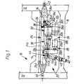
- Fig. 1 10 denotes a partially illustrated subframe, which as far as apparent from two longitudinal bars 12 and a front and a rear cross member 14, 16 composed.
- the cross-sectional profile of the cross member 14, 16 is shown in FIG. 3 .
- the subframe 10 which is connected in a manner not shown to the structure of the motor vehicle (rigid or elastic), carries in a known manner, inter alia, the drive unit of the motor vehicle (see Fig. 3 ), consisting of the engine 18 and the speed Change gear 20 with possibly integrated differential (not shown) composed.
- the steering device 22 (see in particular Fig. 1 ) is composed of a hydraulically assisted rack and pinion steering 24 and a control module 26, which are bolted together in a manner to be described.
- the adjusting module 26, in turn, viewed in the direction of flow of force consists of a torque actuator 28, a steering valve 30 and a servomotor 32, which are connected in series behind one another and which have a common drive-through shaft 26a.
- a first angle drive or bevel gear 34 with bevel gears 34a, 34b is provided on a corresponding output shaft 26b, which drives the rack (not shown) of the rack and pinion steering 24 via an input shaft 36 with a drive pinion 38.
- the rack to both sides of the leading to the steerable wheels of the motor vehicle tie rods 40, 42 (only partially shown) are connected, is guided displaceably in the housing 24a of the rack and pinion steering 24 along the indicated rack center axis 24b.
- rack-and-pinion steering system 24 is not described so far as is conventional and familiar to the person skilled in the art.
- a hydraulic piston-cylinder unit is integrated, which is acted upon in power steering systems of the conventional type via the steering valve 30 with hydraulic medium.
- the steering valve 30 is commercially available construction, but with the different arrangement of the drive shaft 26a parallel to the rack center axis 24b.
- the adjusting module 26 has on the input side a second angle drive or bevel gear 44, which is composed of the bevel gears 44a and 44b.
- the bevel gear 44a is connected to the steering column 46 via a universal joint 48, while the bevel gear 44b is drivingly connected to an input shaft 26c of the adjusting module 26.
- the steering column 46 carries in a known manner the Steering wheel of the motor vehicle and is rotatably mounted accordingly (not shown).
- the torque adjuster 28 essentially consists of an electric motor 28a, which can superimpose a drive torque via a control gear 28b with a toothed belt and corresponding toothed belt wheels on the electric motor 28a and the input shaft 26c to the steering torque manually applied via the steering wheel; the actuating gear 28b with the electric motor 28a can rotate freely in the de-energized state. Via an electronic control (not shown) can thus be controlled an additional steering torque.
- the moment sensor for the control can be arranged for example on the steering column between the steering wheel and a first universal joint of the steering column.
- the torque actuator 28 is drivingly connected to the hydraulic steering valve 30, the function of which is a conventional steering valve with e.g. an integrated rotary valve and torsion bar and a corresponding valve housing corresponds.
- the valve housing is connected via integrated or additionally routed lines with the said piston-cylinder unit in the rack and pinion steering 24 and via a flow and a return line to the hydraulic pump and a hydraulic sump (not shown).
- the output of the steering valve 30 is drivingly connected to the servo motor 32, the superposition gear 32b, not shown in detail, the output shaft 26b of the drive shaft 26a has.
- the superposition gear 32b is connected to a driving electric motor 32a, and may be constituted by a simple planetary gear whose input member (eg, the sun gear) is driven via the output member of the steering valve 30 whose output member (eg, the planet carrier) is connected to the output shaft 26b and whose Control element (eg, the internally and externally toothed outer wheel) of the electric motor 32a for superposition of an additional Steering movement is driven.
- the electric motor 32a or the superposition gear 32b must be self-locking or provided with a brake to ensure a through-drive to the output shaft 26b in the inoperative state.
- an angle drive can also be arranged between the electric motor 32a and the superposition gearing 32b.
- the servomotor 32 must also be designed for the higher steering torques occurring during driving.
- the electric motors 28a and 32a are arranged by appropriate design of the adjusting gear 28b (toothed belt or chain drive) or the superposition gear 32b (planetary gear) so that their axes of rotation 28c, 32c also parallel to the rack center axis 24b are aligned.
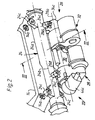
- the bevel drives 34, 44 are rotatably mounted in respective housings 34c, 44c, the housing 44c being connected to the momentum actuator 28 and the housing 34c to the servomotor 32, e.g. by means of fastening screws (not shown in detail) is grown. Further, the torque plate 28, the steering valve 30 and the servo motor 32 are assembled according to their housings (without reference numerals) and secured together.
- the attachment of the steering device 22 on the cross member 14 is accomplished by means of several screws (not shown), the bearing on the housing 24a of the rack and pinion 24 integrally formed bearing eyes 24c (only three bearing eyes 24c are visible) and in corresponding Threaded holes 14 a of the cross member 14 are screwed.
- the control module 26 is screwed to the rack and pinion steering 24, wherein the fastening screws, not shown in FIG according to the housing 24a of the rack and pinion steering 24 integrally formed screw pipes 24c are screwed.
- the torque actuator 28, the steering valve 30 and the actuator 32 are adapted according to their modified arrangement and their assembly, although they may be of a substantially known type.
- the entire control module 26 can be positioned within the subframe 10, wherein the Winkeltriebe or bevel gears 34, 44 further freedom in the spatial positioning of the connection of the steering column 46, 48 and the arrangement and direction of rotation Enable input shaft 36 with the drive pinion 38 of the rack and pinion steering 24.
- torque controller 28 and / or the servomotor 32 are not to be installed in different types of vehicles, appropriate, structurally simple adapters can possibly be installed, whereby significant changes in the adjacent components or the rack and pinion steering 24 are avoided.
- the steering device 22 may also be attached to the two cross members 14, 16 and / or to the longitudinal bars 12 of the subframe 10.
Landscapes
- Engineering & Computer Science (AREA)
- Chemical & Material Sciences (AREA)
- Combustion & Propulsion (AREA)
- Transportation (AREA)
- Mechanical Engineering (AREA)
- Steering Control In Accordance With Driving Conditions (AREA)
- Power Steering Mechanism (AREA)
Claims (10)
- Dispositif de direction pour des véhicules automobiles, avec une direction à crémaillère (24) actionnable par l'intermédiaire d'un organe de direction commandé manuellement qui est formé par un volant de direction et une colonne de direction (46, 48) et présente des dispositifs d'asservissement et / ou des dispositifs de superposition qui sont regroupés dans un module de réglage (26), ledit module de réglage (26) étant en relation d'entraînement avec un pignon d'entraînement (38) s'engrenant avec la crémaillère de la direction à crémaillère (24), grâce à quoi le module de réglage (26) est orienté principalement parallèlement à l'axe central de la crémaillère (24b) par rapport à son pont à relais (26a) et le module de réglage (26) est en relation d'entraînement avec le pignon d'entraînement (38) de la direction à crémaillère (24) au moyen d'une première transmission angulaire (34), les colonnes de direction (46, 48) étant en relation d'entraînement avec le module de réglage (26) au moyen d'une seconde transmission angulaire (44).
- Dispositif de direction selon la revendication 1, caractérisé en ce que le module de réglage (26) est monté sur le boîtier (24a) de la direction à crémaillère (24).
- Dispositif de direction selon l'une ou plusieurs des revendications précédentes, caractérisé en ce que le module de réglage (26) présente un actionneur de couple (28) répandant un couple de direction via un moteur électrique actionnable (28a) et un mécanisme de réglage (28b) sur le pignon d'entraînement (38) de la direction à crémaillère (24).
- Dispositif de direction selon l'une ou plusieurs des revendications précédentes, caractérisé en ce que le module de réglage (26) présente un servomoteur (32) répandant un mouvement de direction via un moteur électrique (32a) actionnable et une boîte de superposition (32b) sur le pignon d'entraînement (38) de la direction à crémaillère (24).
- Dispositif de direction selon l'une ou plusieurs des revendications précédentes, caractérisé en ce que le module de réglage (26) présente une soupape de direction (30) d'une direction assistée hydraulique en tant que direction à crémaillère (24).
- Dispositif de direction selon les revendications 3 à 5, caractérisé en ce que dans le sens du flux de force de la colonne de direction (46, 48) jusqu'au pignon d'entraînement (38) de la direction à crémaillère (24), l'actionneur de couple (28) est disposé en amont de la soupape de direction (30) et le servomoteur (32) y est disposé en aval.
- Dispositif de direction selon les revendications 3 à 6, caractérisé en ce que le moteur électrique (28a) de l'actionneur de couple (28) par rapport à son axe de rotation (28c) est également orienté principalement parallèle par rapport à l'axe de la crémaillère (24b).
- Dispositif de direction selon les revendications 4 à 7, caractérisé en ce que le moteur électrique (32a) du servomoteur (32) par rapport à son axe de rotation (32c) est également orienté principalement parallèle par rapport à l'axe de la crémaillère (24b).
- Dispositif de direction selon l'une ou plusieurs des revendications précédentes, caractérisé en ce que le dispositif de direction (22) conjointement avec le module de réglage (26) est monté sur au moins une traverse (14) d'un cadre auxiliaire (10) réceptionnant un mécanisme d'entraînement (18, 20).
- Dispositif de direction selon la revendication 9, caractérisé en ce que le dispositif de direction (22) est positionné avec le module de réglage (26) entre deux traverses (14, 16) d'un cadre auxiliaire (10) fermé par des montants (12) s'étendant en longueur.
Applications Claiming Priority (2)
| Application Number | Priority Date | Filing Date | Title |
|---|---|---|---|
| DE200410011593 DE102004011593B4 (de) | 2004-03-10 | 2004-03-10 | Lenkvorrichtung für Kraftfahrzeuge |
| DE102004011593 | 2004-03-10 |
Publications (2)
| Publication Number | Publication Date |
|---|---|
| EP1574416A1 EP1574416A1 (fr) | 2005-09-14 |
| EP1574416B1 true EP1574416B1 (fr) | 2007-07-18 |
Family
ID=34813633
Family Applications (1)
| Application Number | Title | Priority Date | Filing Date |
|---|---|---|---|
| EP20050001779 Expired - Lifetime EP1574416B1 (fr) | 2004-03-10 | 2005-01-28 | Dispositif de direction pour un véhicule automobile |
Country Status (2)
| Country | Link |
|---|---|
| EP (1) | EP1574416B1 (fr) |
| DE (2) | DE102004011593B4 (fr) |
Family Cites Families (6)
| Publication number | Priority date | Publication date | Assignee | Title |
|---|---|---|---|---|
| GB1028453A (en) * | 1964-03-13 | 1966-05-04 | Austin Motor Co Ltd | Power-assisted steering mechanisms for motor vehicles |
| ES8605734A1 (es) * | 1985-01-14 | 1986-04-01 | Bendiberica Sa | Perfeccionamientos en mecanismos de direccion asistida com- pactos para vehiculos automoviles |
| GB8816857D0 (en) * | 1988-07-15 | 1988-08-17 | Jaguar Cars | Steer angle adjusting apparatus for vehicle |
| US5201818A (en) * | 1990-05-09 | 1993-04-13 | Koyo Seiko Co., Ltd. | Power steering apparatus |
| US6810985B1 (en) * | 1999-12-17 | 2004-11-02 | Zf Lenksysteme Gmbh | Steering device for a vehicle |
| US7284634B2 (en) * | 2001-04-13 | 2007-10-23 | Nsk, Ltd. | Electric power steering apparatus |
-
2004
- 2004-03-10 DE DE200410011593 patent/DE102004011593B4/de not_active Expired - Fee Related
-
2005
- 2005-01-28 DE DE200550001029 patent/DE502005001029D1/de not_active Expired - Lifetime
- 2005-01-28 EP EP20050001779 patent/EP1574416B1/fr not_active Expired - Lifetime
Also Published As
| Publication number | Publication date |
|---|---|
| DE102004011593A1 (de) | 2005-09-29 |
| DE502005001029D1 (de) | 2007-08-30 |
| DE102004011593B4 (de) | 2008-04-30 |
| EP1574416A1 (fr) | 2005-09-14 |
Similar Documents
| Publication | Publication Date | Title |
|---|---|---|
| DE102010027553B4 (de) | Lenkgetriebe mit Doppelritzel | |
| DE19902556B4 (de) | Lenkgetrieb mit redundantem Antrieb | |
| EP1651502B1 (fr) | Mecanisme de direction pour automobile | |
| EP1904358A1 (fr) | Systeme de direction pour une direction a superposition | |
| DE102012213444A1 (de) | Elektrisch unterstütztes Lenkstock-Servolenksystem | |
| DE102020211976A1 (de) | Drehmomentrückmeldungsanordnung für eine Fahrzeuglenksäule | |
| DE102013018436B4 (de) | Lenkgetriebe mit mehreren Ritzeln | |
| WO2001044037A1 (fr) | Dispositif de direction pour vehicules automobiles | |
| WO2004076210A1 (fr) | Bloc stabilisateur | |
| EP1713679B1 (fr) | Systeme de direction pour un vehicule | |
| DE102007004218A1 (de) | Hilfskraftlenkung | |
| EP3265363A1 (fr) | Arbre d'entrée monobloc | |
| DE10142388B4 (de) | Hilfsrahmenanordnung für ein Kraftfahrzeug und Kraftfahrzeug | |
| DE102015217050A1 (de) | Nutzfahrzeuglenkung | |
| EP2585357B1 (fr) | Arbre de direction soutenu en rotation | |
| WO2014019694A1 (fr) | Mécanisme de direction pour un véhicule à moteur | |
| DE202004003949U1 (de) | Motorische Lenkhilfe für Kraftfahrzeuge | |
| DE102004011593B4 (de) | Lenkvorrichtung für Kraftfahrzeuge | |
| WO2006002790A1 (fr) | Direction a superposition | |
| DE10234596B3 (de) | Als Kugelumlauflenkung ausgebildete elektrische Servolenkung eines Kraftfahrzeuges | |
| DE4023943A1 (de) | Servobremsanlage fuer ein kraftfahrzeug | |
| DE102005014560B4 (de) | Überlagerungslenkung für ein Fahrzeug | |
| DE4408828C2 (de) | Motorische Lenkhilfe für Kraftfahrzeuge | |
| WO2008128592A1 (fr) | Système de direction pour un véhicule | |
| DE10250300A1 (de) | Servo-Lenkanlage |
Legal Events
| Date | Code | Title | Description |
|---|---|---|---|
| PUAI | Public reference made under article 153(3) epc to a published international application that has entered the european phase |
Free format text: ORIGINAL CODE: 0009012 |
|
| AK | Designated contracting states |
Kind code of ref document: A1 Designated state(s): AT BE BG CH CY CZ DE DK EE ES FI FR GB GR HU IE IS IT LI LT LU MC NL PL PT RO SE SI SK TR |
|
| AX | Request for extension of the european patent |
Extension state: AL BA HR LV MK YU |
|
| 17P | Request for examination filed |
Effective date: 20060314 |
|
| AKX | Designation fees paid |
Designated state(s): DE FR GB |
|
| GRAP | Despatch of communication of intention to grant a patent |
Free format text: ORIGINAL CODE: EPIDOSNIGR1 |
|
| GRAS | Grant fee paid |
Free format text: ORIGINAL CODE: EPIDOSNIGR3 |
|
| GRAA | (expected) grant |
Free format text: ORIGINAL CODE: 0009210 |
|
| AK | Designated contracting states |
Kind code of ref document: B1 Designated state(s): DE FR GB |
|
| REG | Reference to a national code |
Ref country code: GB Ref legal event code: FG4D Free format text: NOT ENGLISH |
|
| GBT | Gb: translation of ep patent filed (gb section 77(6)(a)/1977) |
Effective date: 20070808 |
|
| REF | Corresponds to: |
Ref document number: 502005001029 Country of ref document: DE Date of ref document: 20070830 Kind code of ref document: P |
|
| ET | Fr: translation filed | ||
| PLBE | No opposition filed within time limit |
Free format text: ORIGINAL CODE: 0009261 |
|
| STAA | Information on the status of an ep patent application or granted ep patent |
Free format text: STATUS: NO OPPOSITION FILED WITHIN TIME LIMIT |
|
| 26N | No opposition filed |
Effective date: 20080421 |
|
| REG | Reference to a national code |
Ref country code: DE Ref legal event code: R084 Ref document number: 502005001029 Country of ref document: DE Effective date: 20130117 |
|
| REG | Reference to a national code |
Ref country code: FR Ref legal event code: PLFP Year of fee payment: 12 |
|
| PGFP | Annual fee paid to national office [announced via postgrant information from national office to epo] |
Ref country code: DE Payment date: 20160131 Year of fee payment: 12 |
|
| PGFP | Annual fee paid to national office [announced via postgrant information from national office to epo] |
Ref country code: GB Payment date: 20160127 Year of fee payment: 12 Ref country code: FR Payment date: 20160128 Year of fee payment: 12 |
|
| REG | Reference to a national code |
Ref country code: DE Ref legal event code: R119 Ref document number: 502005001029 Country of ref document: DE |
|
| GBPC | Gb: european patent ceased through non-payment of renewal fee |
Effective date: 20170128 |
|
| REG | Reference to a national code |
Ref country code: FR Ref legal event code: ST Effective date: 20170929 |
|
| PG25 | Lapsed in a contracting state [announced via postgrant information from national office to epo] |
Ref country code: FR Free format text: LAPSE BECAUSE OF NON-PAYMENT OF DUE FEES Effective date: 20170131 |
|
| PG25 | Lapsed in a contracting state [announced via postgrant information from national office to epo] |
Ref country code: GB Free format text: LAPSE BECAUSE OF NON-PAYMENT OF DUE FEES Effective date: 20170128 Ref country code: DE Free format text: LAPSE BECAUSE OF NON-PAYMENT OF DUE FEES Effective date: 20170801 |