EP1574416B1 - Steering apparatus for a motor vehicle - Google Patents
Steering apparatus for a motor vehicle Download PDFInfo
- Publication number
- EP1574416B1 EP1574416B1 EP20050001779 EP05001779A EP1574416B1 EP 1574416 B1 EP1574416 B1 EP 1574416B1 EP 20050001779 EP20050001779 EP 20050001779 EP 05001779 A EP05001779 A EP 05001779A EP 1574416 B1 EP1574416 B1 EP 1574416B1
- Authority
- EP
- European Patent Office
- Prior art keywords
- steering
- rack
- pinion
- steering apparatus
- drive
- Prior art date
- Legal status (The legal status is an assumption and is not a legal conclusion. Google has not performed a legal analysis and makes no representation as to the accuracy of the status listed.)
- Expired - Lifetime
Links
Images

Classifications
-
- B—PERFORMING OPERATIONS; TRANSPORTING
- B62—LAND VEHICLES FOR TRAVELLING OTHERWISE THAN ON RAILS
- B62D—MOTOR VEHICLES; TRAILERS
- B62D5/00—Power-assisted or power-driven steering
- B62D5/04—Power-assisted or power-driven steering electrical, e.g. using an electric servo-motor connected to, or forming part of, the steering gear
-
- B—PERFORMING OPERATIONS; TRANSPORTING
- B62—LAND VEHICLES FOR TRAVELLING OTHERWISE THAN ON RAILS
- B62D—MOTOR VEHICLES; TRAILERS
- B62D3/00—Steering gears
- B62D3/02—Steering gears mechanical
- B62D3/12—Steering gears mechanical of rack-and-pinion type
-
- B—PERFORMING OPERATIONS; TRANSPORTING
- B62—LAND VEHICLES FOR TRAVELLING OTHERWISE THAN ON RAILS
- B62D—MOTOR VEHICLES; TRAILERS
- B62D5/00—Power-assisted or power-driven steering
- B62D5/008—Changing the transfer ratio between the steering wheel and the steering gear by variable supply of energy, e.g. by using a superposition gear
-
- B—PERFORMING OPERATIONS; TRANSPORTING
- B62—LAND VEHICLES FOR TRAVELLING OTHERWISE THAN ON RAILS
- B62D—MOTOR VEHICLES; TRAILERS
- B62D5/00—Power-assisted or power-driven steering
- B62D5/04—Power-assisted or power-driven steering electrical, e.g. using an electric servo-motor connected to, or forming part of, the steering gear
- B62D5/0409—Electric motor acting on the steering column
- B62D5/0412—Electric motor acting on the steering column the axes of motor and steering column being parallel
Definitions
- the invention relates to a steering device for motor vehicles according to the preamble of claim 1.
- the EP 0 566 168 A discloses a steering device for motor vehicles, with a rack and pinion steering, which is controlled by a manually operable steering member, which is formed by a steering wheel and a steering column, and the auxiliary power means and / or superposition devices, which are combined in a control module, which control module with a with the rack of the rack and pinion steering meshing drive pinion is drivingly connected, wherein the adjusting module is aligned with respect to its drive shaft substantially parallel to the rack center axis, wherein the control module, the drive pinion of the rack and pinion steering and the steering column are drivingly connected to each other by means of a single angle drive.
- the object of the invention is to develop a steering device of the generic type so that it is structurally even more compact and manufacturing technology even cheaper, while further simplified assembly in the vehicle.
- the drive connection between the steering column and the control module is produced by a second angle drive in a steering device with a manually operated steering wheel and a steering column.
- the steering column thus remains free of adjusting modules of the auxiliary power device and / or superimposition device, so that the structurally particularly cramped footwell and fitting area of the motor vehicle is structurally equalized and improved ergonomic and safety requirements can be adjusted.
- the oscillatory mass in the strand of the steering column is missing. It can neither feel noticeable bending hole Form torsional vibrations in the comfort-relevant area.
- the slim steering column would also be cheaper to telescope in an impact.
- the control module can preferably be attached to the housing of the rack and pinion steering and thus mounted as a mounting unit in the motor vehicle.
- control module can have a steering torque via a controllable electric motor and a control gear on the drive pinion torque governor and / or a steering movement via a controllable electric motor and a superposition gear on the drive pinion applying servomotor and / or the steering valve of a hydraulic power steering rack.
- a preferred construction is further achieved when viewed in the direction of power flow from the steering column to the drive pinion of the rack-and-pinion steering, the torque actuator upstream of the steering valve and the servomotor are arranged downstream thereto.
- the torque controller then acts in the low torque range of the manual steering operation, while the positioning motor for the superposition the steering movement acts in the higher torque range downstream of the steering valve and is designed to be correspondingly stronger in the drive power.
- a structurally particularly favorable design of the steering device is further achieved when the electric motor of the torque controller and / or the electric motor of the servomotor or their axes of rotation are also aligned substantially parallel to the rack axis; the control gear or the superposition gearbox should be adjusted accordingly. This facilitates the insertion of the steering device with the control module in an existing space, wherein perpendicular to the rack axis projecting or projecting components of the control module are avoided.
- An inventive arrangement of the steering device in a motor vehicle is that the steering device is mounted with the control module on at least one cross member of a drive unit receiving subframe. This is under utilization of the space below the drive unit usually available space within the subframe created an arrangement that allows a favorable pre-assembly on the subframe, wherein also the connection of the steering column outside the vehicle interior is easy to produce.
- the steering device can be positioned with the control module between two cross members of a subframe closed by longitudinal spars subframe. This results in a spatially favorable and specially protected arrangement with stable and vibration-resistant attachment of the steering device. Possibly. the housing of the rack and pinion steering can be integrated into the one cross member or replace it by appropriate connection with the longitudinal bars of the subframe.
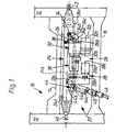
- Fig. 1 10 denotes a partially illustrated subframe, which as far as apparent from two longitudinal bars 12 and a front and a rear cross member 14, 16 composed.
- the cross-sectional profile of the cross member 14, 16 is shown in FIG. 3 .
- the subframe 10 which is connected in a manner not shown to the structure of the motor vehicle (rigid or elastic), carries in a known manner, inter alia, the drive unit of the motor vehicle (see Fig. 3 ), consisting of the engine 18 and the speed Change gear 20 with possibly integrated differential (not shown) composed.
- the steering device 22 (see in particular Fig. 1 ) is composed of a hydraulically assisted rack and pinion steering 24 and a control module 26, which are bolted together in a manner to be described.
- the adjusting module 26, in turn, viewed in the direction of flow of force consists of a torque actuator 28, a steering valve 30 and a servomotor 32, which are connected in series behind one another and which have a common drive-through shaft 26a.
- a first angle drive or bevel gear 34 with bevel gears 34a, 34b is provided on a corresponding output shaft 26b, which drives the rack (not shown) of the rack and pinion steering 24 via an input shaft 36 with a drive pinion 38.
- the rack to both sides of the leading to the steerable wheels of the motor vehicle tie rods 40, 42 (only partially shown) are connected, is guided displaceably in the housing 24a of the rack and pinion steering 24 along the indicated rack center axis 24b.
- rack-and-pinion steering system 24 is not described so far as is conventional and familiar to the person skilled in the art.
- a hydraulic piston-cylinder unit is integrated, which is acted upon in power steering systems of the conventional type via the steering valve 30 with hydraulic medium.
- the steering valve 30 is commercially available construction, but with the different arrangement of the drive shaft 26a parallel to the rack center axis 24b.
- the adjusting module 26 has on the input side a second angle drive or bevel gear 44, which is composed of the bevel gears 44a and 44b.
- the bevel gear 44a is connected to the steering column 46 via a universal joint 48, while the bevel gear 44b is drivingly connected to an input shaft 26c of the adjusting module 26.
- the steering column 46 carries in a known manner the Steering wheel of the motor vehicle and is rotatably mounted accordingly (not shown).
- the torque adjuster 28 essentially consists of an electric motor 28a, which can superimpose a drive torque via a control gear 28b with a toothed belt and corresponding toothed belt wheels on the electric motor 28a and the input shaft 26c to the steering torque manually applied via the steering wheel; the actuating gear 28b with the electric motor 28a can rotate freely in the de-energized state. Via an electronic control (not shown) can thus be controlled an additional steering torque.
- the moment sensor for the control can be arranged for example on the steering column between the steering wheel and a first universal joint of the steering column.
- the torque actuator 28 is drivingly connected to the hydraulic steering valve 30, the function of which is a conventional steering valve with e.g. an integrated rotary valve and torsion bar and a corresponding valve housing corresponds.
- the valve housing is connected via integrated or additionally routed lines with the said piston-cylinder unit in the rack and pinion steering 24 and via a flow and a return line to the hydraulic pump and a hydraulic sump (not shown).
- the output of the steering valve 30 is drivingly connected to the servo motor 32, the superposition gear 32b, not shown in detail, the output shaft 26b of the drive shaft 26a has.
- the superposition gear 32b is connected to a driving electric motor 32a, and may be constituted by a simple planetary gear whose input member (eg, the sun gear) is driven via the output member of the steering valve 30 whose output member (eg, the planet carrier) is connected to the output shaft 26b and whose Control element (eg, the internally and externally toothed outer wheel) of the electric motor 32a for superposition of an additional Steering movement is driven.
- the electric motor 32a or the superposition gear 32b must be self-locking or provided with a brake to ensure a through-drive to the output shaft 26b in the inoperative state.
- an angle drive can also be arranged between the electric motor 32a and the superposition gearing 32b.
- the servomotor 32 must also be designed for the higher steering torques occurring during driving.
- the electric motors 28a and 32a are arranged by appropriate design of the adjusting gear 28b (toothed belt or chain drive) or the superposition gear 32b (planetary gear) so that their axes of rotation 28c, 32c also parallel to the rack center axis 24b are aligned.
- the bevel drives 34, 44 are rotatably mounted in respective housings 34c, 44c, the housing 44c being connected to the momentum actuator 28 and the housing 34c to the servomotor 32, e.g. by means of fastening screws (not shown in detail) is grown. Further, the torque plate 28, the steering valve 30 and the servo motor 32 are assembled according to their housings (without reference numerals) and secured together.
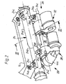
- the attachment of the steering device 22 on the cross member 14 is accomplished by means of several screws (not shown), the bearing on the housing 24a of the rack and pinion 24 integrally formed bearing eyes 24c (only three bearing eyes 24c are visible) and in corresponding Threaded holes 14 a of the cross member 14 are screwed.
- the control module 26 is screwed to the rack and pinion steering 24, wherein the fastening screws, not shown in FIG according to the housing 24a of the rack and pinion steering 24 integrally formed screw pipes 24c are screwed.
- the torque actuator 28, the steering valve 30 and the actuator 32 are adapted according to their modified arrangement and their assembly, although they may be of a substantially known type.
- the entire control module 26 can be positioned within the subframe 10, wherein the Winkeltriebe or bevel gears 34, 44 further freedom in the spatial positioning of the connection of the steering column 46, 48 and the arrangement and direction of rotation Enable input shaft 36 with the drive pinion 38 of the rack and pinion steering 24.
- torque controller 28 and / or the servomotor 32 are not to be installed in different types of vehicles, appropriate, structurally simple adapters can possibly be installed, whereby significant changes in the adjacent components or the rack and pinion steering 24 are avoided.
- the steering device 22 may also be attached to the two cross members 14, 16 and / or to the longitudinal bars 12 of the subframe 10.
Landscapes
- Engineering & Computer Science (AREA)
- Chemical & Material Sciences (AREA)
- Combustion & Propulsion (AREA)
- Transportation (AREA)
- Mechanical Engineering (AREA)
- Steering Control In Accordance With Driving Conditions (AREA)
- Power Steering Mechanism (AREA)
Description
Die Erfindung betrifft eine Lenkvorrichtung für Kraftfahrzeuge gemäß dem Oberbegriff des Patentanspruches 1.The invention relates to a steering device for motor vehicles according to the preamble of claim 1.
Weit verbreitet in Kraftfahrzeugen sind hydraulisch unterstützte Hilfskraftlenkungen, die auch als Zahnstangenlenkungen ausgeführt sein können. Das hydraulische Lenkventil als Stellmodul dieser Hilfskrafteinrichtung sitzt dabei in der Regel zwischen der Lenksäule und dem Antriebsritzel der Zahnstange. Zur Weiterentwicklung solcher Lenkvorrichtungen sind auch schon Momentensteller mit elektrischem Antrieb vorgeschlagen worden, die die Haptik der Lenkvorrichtung verbessern (Fahrzeug folgt entsprechend elektronisch geregelt dem Fahrbahnverlauf, kann aber manuell z.B. zum Ausweichen eines Hindernisses übersteuert werden). Ferner sind bereits Stellmotoren mit einem Elektromotor und einem Überlagerungsgetriebe vorgeschlagen worden, die in die Lenksäule integriert der manuellen Lenkbetätigung eine zusätzliche Lenkbewegung überlagern, z.B. zur Erzielung einer variablen Lenkübersetzung, etc. Schließlich wurden auch bereits Lenkvorrichtungen vorgeschlagen (steer by wire), die keine mechanische Verbindung mehr zum manuell betätigten Lenkorgan (Entfall der Lenksäule, etc) aufweisen.Widely used in motor vehicles are hydraulically assisted power steering systems, which can also be designed as rack and pinion steering systems. The hydraulic steering valve as a control module of this auxiliary power device usually sits between the steering column and the drive pinion of the rack. For the further development of such steering devices, momentary actuators with electric drive have also been proposed, which improve the feel of the steering device (vehicle accordingly follows the course of the road electronically, but can be manually overridden, for example, to avoid an obstacle). Furthermore, servomotors have already been proposed with an electric motor and a superposition gear, which integrated into the steering column of the manual steering operation superimpose an additional steering movement, e.g. to achieve a variable steering ratio, etc. Finally, steering devices have already been proposed (steer by wire), which no longer have a mechanical connection to the manually operated steering element (elimination of the steering column, etc).
Insbesondere in Personenkraftfahrzeugen ist die Anordnung der beschriebenen Hilfskrafteinrichtungen bzw. Überlagerungseinrichtungen aufgrund des beengten Bauraumes im Bereich der Lenkvorrichtung problematisch und zwingt zu kostenintensiven Kompromissen.In particular, in passenger vehicles, the arrangement of the described auxiliary power devices or superposition devices Due to the limited space in the steering device problematic and forces to costly compromises.
Die
Aufgabe der Erfindung ist es, eine Lenkvorrichtung der gattungsgemäßen Art so weiterzubilden, dass diese baulich noch gedrängter und fertigungstechnisch noch günstiger ausgeführt ist, bei gleichzeitig weiter vereinfachter Montage im Kraftfahrzeug.The object of the invention is to develop a steering device of the generic type so that it is structurally even more compact and manufacturing technology even cheaper, while further simplified assembly in the vehicle.
Diese Aufgabe wird erfindungsgemäß mit den Merkmalen des Patentanspruches 1 gelöst. Vorteilhafte Weiterbildungen der Erfindung sind den Unteransprüchen entnehmbar.This object is achieved by the features of claim 1. Advantageous developments of the invention can be taken from the subclaims.
Erfindungsgemäß ist bei einer Lenkvorrichtung mit einem manuell zu betätigenden Lenkhandrad und einer Lenksäule die triebliche Verbindung zwischen der Lenksäule und dem Stellmodul durch einen zweiten Winkeltrieb hergestellt. Die Lenksäule bleibt damit frei von Stellmodulen der Hilfskrafteinrichtung und/oder Überlagerungseinrichtung, so dass der baulich besonders beengte Fußraum- und Armaturenbereich des Kraftfahrzeuges konstruktiv entzerrt wird und verbessert ergonomischen und sicherheitstechnischen Anforderungen angepasst werden kann. Es ergibt sich auch der Vorteil, dass die schwingfähige Masse im Strang der Lenksäule fehlt. Es können sich weder spürbare Biegenoch Drehschwingungen im komfortrelevanten Bereich ausbilden. Die schlanke Lenksäule wäre bei einem Aufprall auch günstiger teleskopierbar.According to the invention, the drive connection between the steering column and the control module is produced by a second angle drive in a steering device with a manually operated steering wheel and a steering column. The steering column thus remains free of adjusting modules of the auxiliary power device and / or superimposition device, so that the structurally particularly cramped footwell and fitting area of the motor vehicle is structurally equalized and improved ergonomic and safety requirements can be adjusted. There is also the advantage that the oscillatory mass in the strand of the steering column is missing. It can neither feel noticeable bending hole Form torsional vibrations in the comfort-relevant area. The slim steering column would also be cheaper to telescope in an impact.
Das Stellmodul kann bevorzugt an das Gehäuse der Zahnstangenlenkung angebaut sein und somit als Montageeinheit in das Kraftfahrzeug montiert werden.The control module can preferably be attached to the housing of the rack and pinion steering and thus mounted as a mounting unit in the motor vehicle.
Des weiteren kann das Stellmodul einen ein Lenkmoment über einen ansteuerbaren Elektromotor und ein Stellgetriebe auf das Antriebsritzel aufbringenden Momentensteller und/oder einen eine Lenkbewegung über einen ansteuerbaren Elektromotor und ein Überlagerungsgetriebe auf das Antriebsritzel aufbringenden Stellmotor und/oder das Lenkventil einer hydraulischen Hilfskrafteinrichtung der Zahnstangenlenkung aufweisen. Ohne größere konstruktive Änderungen an den umgebenden Fahrzeug- und Aggregateteilen können je nach technischer Ausstattung des Kraftfahrzeuges alle oder einzelne dieser Hilfskraft- oder Überlagerungseinrichtungen an die Zahnstangenlenkung angebaut und montiert werden.Furthermore, the control module can have a steering torque via a controllable electric motor and a control gear on the drive pinion torque governor and / or a steering movement via a controllable electric motor and a superposition gear on the drive pinion applying servomotor and / or the steering valve of a hydraulic power steering rack. Without major structural changes to the surrounding vehicle and unit parts, depending on the technical equipment of the motor vehicle, all or individual of these auxiliary power or superposition devices can be mounted and mounted on the rack and pinion steering.
Eine bevorzugte Konstruktion wird ferner erzielt, wenn in Kraftflussrichtung von der Lenksäule zum Antriebsritzel der Zahnstangenlenkung betrachtet der Momentensteller stromauf des Lenkventiles und der Stellmotor stromab dazu angeordnet sind. Der Momentensteller wirkt dann im niedrigen Momentenbereich der manuellen Lenkbetätigung, während der Stellmotor für die Überlagerung der Lenkbewegung im höheren Momentenbereich stromab des Lenkventiles agiert und entsprechend stärker in der Antriebsleistung auszulegen ist.A preferred construction is further achieved when viewed in the direction of power flow from the steering column to the drive pinion of the rack-and-pinion steering, the torque actuator upstream of the steering valve and the servomotor are arranged downstream thereto. The torque controller then acts in the low torque range of the manual steering operation, while the positioning motor for the superposition the steering movement acts in the higher torque range downstream of the steering valve and is designed to be correspondingly stronger in the drive power.
Eine baulich besonders günstige Gestaltung der Lenkvorrichtung wird des weiteren dann erzielt, wenn der Elektromotor des Momentenstellers und/oder der Elektromotor des Stellmotors bzw. deren Drehachsen ebenfalls im wesentlichen parallel zur Zahnstangenachse ausgerichtet sind; das Stellgetriebe bzw. das Überlagerungsgetriebe sind entsprechend anzupassen. Dies erleichtert die Einfügung der Lenkvorrichtung mit dem Stellmodul in einen vorhandenen Bauraum, wobei senkrecht zur Zahnstangenachse abstehende bzw. abragende Bauteile des Stellmoduls vermieden sind.A structurally particularly favorable design of the steering device is further achieved when the electric motor of the torque controller and / or the electric motor of the servomotor or their axes of rotation are also aligned substantially parallel to the rack axis; the control gear or the superposition gearbox should be adjusted accordingly. This facilitates the insertion of the steering device with the control module in an existing space, wherein perpendicular to the rack axis projecting or projecting components of the control module are avoided.
Eine erfindungsgemäße Anordnung der Lenkvorrichtung in einem Kraftfahrzeug besteht darin, dass die Lenkvorrichtung mit dem Stellmodul an zumindest einen Querträger eines ein Antriebsaggregat aufnehmenden Hilfsrahmens angebaut ist. Damit ist unter Ausnutzung des unterhalb des Antriebsaggregates in der Regel vorhandenen Bauraumes innerhalb des Hilfsrahmens eine Anordnung geschaffen, die eine günstige Vormontage am Hilfsrahmen ermöglicht, wobei zudem der Anschluss der Lenksäule außerhalb des Fahrzeuginnenraumes gut zugänglich herstellbar ist.An inventive arrangement of the steering device in a motor vehicle is that the steering device is mounted with the control module on at least one cross member of a drive unit receiving subframe. This is under utilization of the space below the drive unit usually available space within the subframe created an arrangement that allows a favorable pre-assembly on the subframe, wherein also the connection of the steering column outside the vehicle interior is easy to produce.
Schließlich kann die Lenkvorrichtung mit dem Stellmodul zwischen zwei Querträgern eines durch längs verlaufende Holme geschlossenen Hilfsrahmens positioniert sein. Dies ergibt eine räumlich günstige und besonders geschützte Anordnung mit stabiler und schwingungsresistenter Befestigung der Lenkvorrichtung. Ggf. kann das Gehäuse der Zahnstangenlenkung in den einen Querträger integriert sein bzw. diesen durch entsprechende Verbindung mit den längs verlaufenden Holmen des Hilfsrahmens ersetzen.Finally, the steering device can be positioned with the control module between two cross members of a subframe closed by longitudinal spars subframe. This results in a spatially favorable and specially protected arrangement with stable and vibration-resistant attachment of the steering device. Possibly. the housing of the rack and pinion steering can be integrated into the one cross member or replace it by appropriate connection with the longitudinal bars of the subframe.
Ein Ausführungsbeispiel der Erfindung ist im folgenden mit weiteren Einzelheiten näher erläutert. Die schematische Zeichnung zeigt in:
- Fig. 1
- eine Draufsicht auf eine Lenkvorrichtung mit einer Zahnstangenlenkung und einem Stellmodul, die zwischen zwei Querträgern eines Hilfsrahmens eines Kraftfahrzeuges angeordnet sind;
- Fig. 2
- eine raumbildliche Darstellung der Lenkvorrichtung nach Fig. 1 mit deren Befestigungsmitteln; und
- Fig. 3
- einen Querschnitt gemäß Linie III - III der Fig. 2 durch die Lenkvorrichtung und den Hilfsrahmen, sowie deren Anordnung unterhalb des Antriebsaggregates des Kraftfahrzeuges.
- Fig. 1
- a plan view of a steering device with a rack and pinion steering and a control module, which are arranged between two cross members of a subframe of a motor vehicle;
- Fig. 2
- a three-dimensional view of the steering device of Figure 1 with their attachment means. and
- Fig. 3
- a cross section along line III - III of Fig. 2 by the steering device and the subframe, and their arrangement below the drive unit of the motor vehicle.
In der Fig. 1 ist mit 10 ein teilweise dargestellter Hilfsrahmen bezeichnet, der sich soweit ersichtlich aus zwei längsverlaufenden Holmen 12 und einem vorderen und einem hinteren Querträger 14, 16 zusammensetzt. Das Querschnittsprofil der Querträger 14, 16 ist aus der Fig. 3 ersichtlich.In Fig. 1 , 10 denotes a partially illustrated subframe, which as far as apparent from two
Der Hilfsrahmen 10, der in nicht dargestellter Weise mit dem Aufbau des Kraftfahrzeuges (starr oder auch elastisch) verbunden ist, trägt in bekannter Weise unter anderem das Antriebsaggregat des Kraftfahrzeuges (vgl. Fig. 3), das sich aus der Brennkraftmaschine 18 und dem Geschwindigkeits-Wechselgetriebe 20 mit ggf. integriertem Differenzial (nicht ersichtlich) zusammensetzt.The
Unterhalb des Antriebsaggregates 18, 20 ist zwischen den beiden Querträgern 14, 16 des Hilfsrahmens 10 eine Lenkvorrichtung 22 in dem innerhalb der Querträger 14, 16 und der längs verlaufenden Holme 12 gebildeten Freiraum angeordnet, die an dem vorderen Querträger 14 befestigt ist.Below the
Die Lenkvorrichtung 22 (vgl. insbesondere Fig. 1) setzt sich aus einer hydraulisch unterstützten Zahnstangenlenkung 24 und einem Stellmodul 26 zusammen, die in noch zu beschreibender Weise miteinander verschraubt sind.The steering device 22 (see in particular Fig. 1 ) is composed of a hydraulically assisted rack and
Das Stellmodul 26 wiederum besteht in Kraftflussrichtung betrachtet aus einem Momentensteller 28, einem Lenkventil 30 und einem Stellmotor 32, die trieblich hintereinander geschaltet sind und die eine gemeinsame Durchtriebsachse 26a aufweisen.The adjusting
Am Ausgang des Stellmoduls 26 ist an einer entsprechenden Ausgangswelle 26b ein erster Winkeltrieb bzw. Kegeltrieb 34 mit Kegelrädern 34a, 34b vorgesehen, der über eine Eingangswelle 36 mit einem Antriebsritzel 38 die Zahnstange (nicht ersichtlich) der Zahnstangenlenkung 24 antreibt. Die Zahnstange, an die beiderseits die zu den lenkbaren Rädern des Kraftfahrzeuges führenden Spurstangen 40, 42 (nur teilweise dargestellt) angeschlossen sind, ist in dem Gehäuse 24a der Zahnstangenlenkung 24 entlang der eingezeichneten Zahnstangenmittelachse 24b verschiebbar geführt.At the output of the
Es sei bemerkt, dass die Zahnstangenlenkung 24 soweit nicht beschrieben herkömmlicher und dem Fachmann geläufiger Bauart ist. Innerhalb des Gehäu-ses 24a ist eine hydraulische Kolben-Zylinder-Einheit integriert, die in bei Servolenkungen üblicher Art über das Lenkventil 30 mit Hydraulikmedium beaufschlagbar ist. Auch das Lenkventil 30 ist handelsüblicher Konstruktion, jedoch mit der unterschiedlichen Anordnung der Durchtriebsachse 26a parallel zur Zahnstangenmittelachse 24b.It should be noted that the rack-and-
Das Stellmodul 26 weist eingangsseitig einen zweiten Winkeltrieb bzw. Kegeltrieb 44 auf, der sich aus den Kegelrädern 44a und 44b zusammensetzt. Dabei ist das Kegelrad 44a mit der Lenksäule 46 über ein Kardangelenk 48 verbunden, während das Kegelrad 44b mit einer Eingangswelle 26c des Stellmoduls 26 trieblich verbunden ist. Die Lenksäule 46 trägt in bekannter Weise das Lenkhandrad des Kraftfahrzeuges und ist entsprechend drehbar gelagert (nicht dargestellt).The adjusting
Der Momentensteller 28 besteht im wesentlichen aus einem Elektromotor 28a, der über ein Stellgetriebe 28b mit einem Zahnriemen und entsprechenden Zahnriemenrädern am Elektromotor 28a und der Eingangswelle 26c dem über das Lenkhandrad manuell aufgebrachten Lenkmoment ein Antriebsmoment überlagern kann; das Stellgetriebe 28b mit dem Elektromotor 28a kann sich im stromlosen Zustand frei mitdrehen. Über eine elektronische Steuerung (nicht dargestellt) kann somit ein zusätzliches Lenkmoment eingesteuert werden. Der Momentensensor für die Steuerung kann beispielsweise an der Lenksäule zwischen Lenkrad und einem ersten Kreuzgelenk der Lenksäule angeordnet sein.The
Der Momentensteller 28 ist trieblich mit dem hydraulischen Lenkventil 30 verbunden, dessen Funktion einem herkömmlichen Lenkventil mit z.B. einem integrierten Drehschieber und Drehstab und einem entsprechenden Ventilgehäuse entspricht. Das Ventilgehäuse ist über integrierte oder zusätzlich verlegte Leitungen mit der besagten Kolben-Zylinder-Einheit in der Zahnstangenlenkung 24 und über eine Vorlauf- und eine Rücklaufleitung mit der Hydraulikpumpe und einem Hydrauliksumpf verbunden (nicht dargestellt).The
Der Ausgang des Lenkventils 30 ist trieblich mit dem Stellmotor 32 verbunden, dessen nicht näher dargestelltes Überlagerungsgetriebe 32b die Ausgangswelle 26b der Durchtriebsachse 26a aufweist. Das Überlagerungsgetriebe 32b ist mit einem antreibenden Elektromotor 32a verbunden und kann durch ein einfaches Planetengetriebe gebildet sein, dessen Eingangselement (z.B. das Sonnenrad) über das Ausgangselement des Lenkventiles 30 angetrieben ist, dessen Ausgangselement (z.B. der Planetenradträger) mit der Ausgangswelle 26b verbunden ist und dessen Stellelement (z.B. das innen und außen verzahnte Außenrad) von dem Elektromotor 32a zur Überlagerung einer zusätzlichen Lenkbewegung angetrieben ist. Der Elektromotor 32a oder das Überlagerungsgetriebe 32b muss selbsthemmend oder mit einer Bremse versehen sein, um im funktionslosen Zustand einen Durchtrieb zur Ausgangswelle 26b sicherzustellen. Zwischen Elektromotor 32a und Überlagerungsgetriebe 32b kann beispielsweise auch ein Winkeltrieb angeordnet sein.Der Stellmotor 32 muss ferner auf die im Fahrbetrieb auftretenden höheren Lenkmomente ausgelegt sein.The output of the steering
Wie aus der Zeichnung Fig. 1 ersichtlich ist, sind die Elektromotore 28a und 32a durch entsprechende Auslegung des Stellgetriebes 28b (Zahnriemen- oder Kettentrieb) bzw. des Überlagerungsgetriebes 32b (Planetengetriebe) so angeordnet, dass deren Drehachsen 28c, 32c ebenfalls parallel zur Zahnstangenmittelachse 24b ausgerichtet sind. 1 , the
Die Winkeltriebe bzw. Kegeltriebe 34, 44 sind in entsprechenden Gehäusen 34c, 44c drehbar gelagert, wobei das Gehäuse 44c an den Momentensteller 28 und das Gehäuse 34c an den Stellmotor 32 z.B. mittels Befestigungsschrauben (nicht näher dargestellt) angebaut ist. Ferner sind der Momentensteller 28, das Lenkventil 30 und der Stellmotor 32 entsprechend mit deren Gehäusen (ohne Bezugszeichen) zusammengebaut und aneinander befestigt.The bevel drives 34, 44 are rotatably mounted in respective housings 34c, 44c, the housing 44c being connected to the
Die Befestigung der Lenkvorrichtung 22 am Querträger 14 (vgl. Fig. 2) ist mittels mehrer Schrauben (nicht eingezeichnet) bewerkstelligt, die an das Gehäuse 24a der Zahnstangenlenkung 24 angeformte Lageraugen 24c (es sind nur drei Lageraugen 24c ersichtlich) durchdringen und die in entsprechende Gewindebohrungen 14a des Querträgers 14 eingeschraubt sind.The attachment of the
Über weitere Lageraugen 26d, die an das Gehäuse des Stellmoduls 26 bzw. an die Gehäuse (ohne Bezugszeichen) des Momentenstellers 28 und des Kegeltriebes 34 angeformt sind, ist das Stellmodul 26 an der Zahnstangenlenkung 24 angeschraubt, wobei die nicht dargestellten Befestigungsschrauben in entsprechend an das Gehäuse 24a der Zahnstangenlenkung 24 angeformte Schraubenpfeifen 24c eingeschraubt sind.About another bearing lugs 26 d, which are integrally formed on the housing of the
Es versteht sich, dass der Momentensteller 28, das Lenkventil 30 und der Stellmotor 32 entsprechend ihrer modifizierten Anordnung und ihrem Zusammenbau anzupassen sind, obwohl sie im wesentlichen bekannter Bauart sein können. Durch deren zur Zahnstangenmittelachse 24b parallele Ausrichtung kann das gesamte Stellmodul 26 innerhalb des Hilfsrahmens 10 positioniert werden, wobei die Winkeltriebe bzw. Kegeltriebe 34, 44 ferner eine weitgehende Freiheit bei der räumlichen Positionierung des Anschlusses der Lenksäule 46, 48 und bei der Anordnung und Drehrichtung der Eingangswelle 36 mit dem Antriebsritzel 38 der Zahnstangenlenkung 24 ermöglichen.It is understood that the
Falls der Momentensteller 28 und/oder der Stellmotor 32 bei unterschiedlichen Fahrzeugtypen nicht verbaut werden sollen, können ggf. entsprechende, baulich einfach ausgeführte Adapter verbaut werden, wodurch wesentliche Änderungen der angrenzenden Bauteile oder der Zahnstangenlenkung 24 vermieden sind.If the
Die Lenkvorrichtung 22 kann auch an den beiden Querträgern 14, 16 und/oder an den längs verlaufenden Holmen 12 des Hilfsrahmens 10 befestigt sein.The
Claims (10)
- Steering apparatus for motor vehicles, with a rack-and-pinion steering mechanism (24) which is operable by a manually controllable steering element constituted by a steering wheel and a steering column (46, 48) and has power-assist devices and/or superimposition devices that are grouped in a servo module (26) kinematically connected to a drive pinion (38) meshing with the rack of the rack-and-pinion steering mechanism (24), wherein the servo module (26) is orientated with its drive-line axis (26a) substantially parallel with the rack's central axis (24b) and is kinematically connected to the drive pinion (38) of the rack-and-pinion steering mechanism (24) by a first bevel gear (34), [and] wherein the steering column (46, 48) is kinematically connected to the servo module (26) through a second bevel gear (44).
- Steering apparatus according to Claim 1, characterized in that the servo module (26) is mounted on the housing (24a) of the rack-and-pinion steering mechanism (24).
- Steering apparatus according to one or more of the preceding claims, characterized in that the servo module (26) has a torque control element (28) applying steering torque through an addressable electric motor (28a) and an actuating gear (28b) to the drive pinion (38) of the rack-and-pinion steering mechanism (24).
- Steering apparatus according to one or more of the preceding claims, characterized in that the servo module (26) has a servo motor (32) imparting steering motion through an addressable electric motor (32a) and a superimposition gear (32b) to the drive pinion (38) of the rack-and-pinion steering mechanism (24).
- Steering apparatus according to one or more of the preceding claims, characterized in that the servo module (26) comprises a steering valve (30) of a hydraulic power-assisted steering unit as the rack-and-pinion steering mechanism (24).
- Steering apparatus according to Claims 3 to 5, characterized in that the torque control element (28) is located upstream of, and the servo motor (32), downstream of, the steering valve (30), in the direction of power flow from the steering column (46, 48) to the drive pinion (38) of the rack-and-pinion steering mechanism (24).
- Steering apparatus according to any one of Claims 3 to 6, characterized in that the electric motor (28a) of the torque control element (28) is also orientated with its rotational axis (28c) substantially parallel with the rack axis (24b).
- Steering apparatus according to any one of Claims 4 to 7, characterized in that the electric motor (32a) of the servo motor (32) is also orientated with its rotational axis (32c) substantially parallel with the rack axis (24b).
- Steering apparatus according to one or more of the preceding claims, characterized in that the steering apparatus (22) with the servo module (26) is mounted on at least one crossmember (14) of a subframe (10) carrying a drive unit (18, 20).
- Steering apparatus according to Claim 9, characterized in that the steering apparatus (22) with the servo module (26) is positioned between two crossmembers (14, 16) of a subframe (10) closed by longitudinal spars (12).
Applications Claiming Priority (2)
| Application Number | Priority Date | Filing Date | Title |
|---|---|---|---|
| DE200410011593 DE102004011593B4 (en) | 2004-03-10 | 2004-03-10 | Steering device for motor vehicles |
| DE102004011593 | 2004-03-10 |
Publications (2)
| Publication Number | Publication Date |
|---|---|
| EP1574416A1 EP1574416A1 (en) | 2005-09-14 |
| EP1574416B1 true EP1574416B1 (en) | 2007-07-18 |
Family
ID=34813633
Family Applications (1)
| Application Number | Title | Priority Date | Filing Date |
|---|---|---|---|
| EP20050001779 Expired - Lifetime EP1574416B1 (en) | 2004-03-10 | 2005-01-28 | Steering apparatus for a motor vehicle |
Country Status (2)
| Country | Link |
|---|---|
| EP (1) | EP1574416B1 (en) |
| DE (2) | DE102004011593B4 (en) |
Family Cites Families (6)
| Publication number | Priority date | Publication date | Assignee | Title |
|---|---|---|---|---|
| GB1028453A (en) * | 1964-03-13 | 1966-05-04 | Austin Motor Co Ltd | Power-assisted steering mechanisms for motor vehicles |
| ES8605734A1 (en) * | 1985-01-14 | 1986-04-01 | Bendiberica Sa | Compact servosteering mechanism for an automotive vehicle. |
| GB8816857D0 (en) * | 1988-07-15 | 1988-08-17 | Jaguar Cars | Steer angle adjusting apparatus for vehicle |
| US5201818A (en) * | 1990-05-09 | 1993-04-13 | Koyo Seiko Co., Ltd. | Power steering apparatus |
| US6810985B1 (en) * | 1999-12-17 | 2004-11-02 | Zf Lenksysteme Gmbh | Steering device for a vehicle |
| US7284634B2 (en) * | 2001-04-13 | 2007-10-23 | Nsk, Ltd. | Electric power steering apparatus |
-
2004
- 2004-03-10 DE DE200410011593 patent/DE102004011593B4/en not_active Expired - Fee Related
-
2005
- 2005-01-28 DE DE200550001029 patent/DE502005001029D1/en not_active Expired - Lifetime
- 2005-01-28 EP EP20050001779 patent/EP1574416B1/en not_active Expired - Lifetime
Also Published As
| Publication number | Publication date |
|---|---|
| DE102004011593A1 (en) | 2005-09-29 |
| DE502005001029D1 (en) | 2007-08-30 |
| DE102004011593B4 (en) | 2008-04-30 |
| EP1574416A1 (en) | 2005-09-14 |
Similar Documents
| Publication | Publication Date | Title |
|---|---|---|
| DE102010027553B4 (en) | Steering gear with double pinion | |
| DE19902556B4 (en) | Steering gear with redundant drive | |
| EP1651502B1 (en) | Steering gear for a motor vehicle | |
| EP1904358A1 (en) | Steering device for a superposition steering system | |
| DE102012213444A1 (en) | Electrically assisted steering column power steering system | |
| DE102020211976A1 (en) | Torque feedback arrangement for a vehicle steering column | |
| DE102013018436B4 (en) | Multiple pinion steering gear | |
| WO2001044037A1 (en) | Steering device for a vehicle | |
| WO2004076210A1 (en) | Stabilizer subassembly | |
| EP1713679B1 (en) | Steering system for a vehicle | |
| DE102007004218A1 (en) | servo-steering mechanism for motor vehicle, has servo motor, which forms actuator with gear train for supply of steering auxiliary force and gear train has output element | |
| EP3265363A1 (en) | One-piece input shaft | |
| DE10142388B4 (en) | Subframe assembly for a motor vehicle and motor vehicle | |
| DE102015217050A1 (en) | Commercial vehicle steering | |
| EP2585357B1 (en) | Rotationally supported steering spindle | |
| WO2014019694A1 (en) | Steering gear for a motor vehicle | |
| DE202004003949U1 (en) | Powered steering booster for vehicle with two or more servomotors in parallel arrangement to provide auxiliary torque to steering shaft | |
| DE102004011593B4 (en) | Steering device for motor vehicles | |
| WO2006002790A1 (en) | Superimposed steering system | |
| DE10234596B3 (en) | As recirculating ball steering trained electric power steering a motor vehicle | |
| DE4023943A1 (en) | SERVO BRAKE SYSTEM FOR A MOTOR VEHICLE | |
| DE102005014560B4 (en) | Overhead steering for a vehicle | |
| DE4408828C2 (en) | Motorized steering aid for motor vehicles | |
| WO2008128592A1 (en) | Steering arrangement for a motor vehicle | |
| DE10250300A1 (en) | Servo-steering system |
Legal Events
| Date | Code | Title | Description |
|---|---|---|---|
| PUAI | Public reference made under article 153(3) epc to a published international application that has entered the european phase |
Free format text: ORIGINAL CODE: 0009012 |
|
| AK | Designated contracting states |
Kind code of ref document: A1 Designated state(s): AT BE BG CH CY CZ DE DK EE ES FI FR GB GR HU IE IS IT LI LT LU MC NL PL PT RO SE SI SK TR |
|
| AX | Request for extension of the european patent |
Extension state: AL BA HR LV MK YU |
|
| 17P | Request for examination filed |
Effective date: 20060314 |
|
| AKX | Designation fees paid |
Designated state(s): DE FR GB |
|
| GRAP | Despatch of communication of intention to grant a patent |
Free format text: ORIGINAL CODE: EPIDOSNIGR1 |
|
| GRAS | Grant fee paid |
Free format text: ORIGINAL CODE: EPIDOSNIGR3 |
|
| GRAA | (expected) grant |
Free format text: ORIGINAL CODE: 0009210 |
|
| AK | Designated contracting states |
Kind code of ref document: B1 Designated state(s): DE FR GB |
|
| REG | Reference to a national code |
Ref country code: GB Ref legal event code: FG4D Free format text: NOT ENGLISH |
|
| GBT | Gb: translation of ep patent filed (gb section 77(6)(a)/1977) |
Effective date: 20070808 |
|
| REF | Corresponds to: |
Ref document number: 502005001029 Country of ref document: DE Date of ref document: 20070830 Kind code of ref document: P |
|
| ET | Fr: translation filed | ||
| PLBE | No opposition filed within time limit |
Free format text: ORIGINAL CODE: 0009261 |
|
| STAA | Information on the status of an ep patent application or granted ep patent |
Free format text: STATUS: NO OPPOSITION FILED WITHIN TIME LIMIT |
|
| 26N | No opposition filed |
Effective date: 20080421 |
|
| REG | Reference to a national code |
Ref country code: DE Ref legal event code: R084 Ref document number: 502005001029 Country of ref document: DE Effective date: 20130117 |
|
| REG | Reference to a national code |
Ref country code: FR Ref legal event code: PLFP Year of fee payment: 12 |
|
| PGFP | Annual fee paid to national office [announced via postgrant information from national office to epo] |
Ref country code: DE Payment date: 20160131 Year of fee payment: 12 |
|
| PGFP | Annual fee paid to national office [announced via postgrant information from national office to epo] |
Ref country code: GB Payment date: 20160127 Year of fee payment: 12 Ref country code: FR Payment date: 20160128 Year of fee payment: 12 |
|
| REG | Reference to a national code |
Ref country code: DE Ref legal event code: R119 Ref document number: 502005001029 Country of ref document: DE |
|
| GBPC | Gb: european patent ceased through non-payment of renewal fee |
Effective date: 20170128 |
|
| REG | Reference to a national code |
Ref country code: FR Ref legal event code: ST Effective date: 20170929 |
|
| PG25 | Lapsed in a contracting state [announced via postgrant information from national office to epo] |
Ref country code: FR Free format text: LAPSE BECAUSE OF NON-PAYMENT OF DUE FEES Effective date: 20170131 |
|
| PG25 | Lapsed in a contracting state [announced via postgrant information from national office to epo] |
Ref country code: GB Free format text: LAPSE BECAUSE OF NON-PAYMENT OF DUE FEES Effective date: 20170128 Ref country code: DE Free format text: LAPSE BECAUSE OF NON-PAYMENT OF DUE FEES Effective date: 20170801 |