EP1574414B1 - Verstellbare Kraftfahrzeuglenksäule - Google Patents
Verstellbare Kraftfahrzeuglenksäule Download PDFInfo
- Publication number
- EP1574414B1 EP1574414B1 EP05101250A EP05101250A EP1574414B1 EP 1574414 B1 EP1574414 B1 EP 1574414B1 EP 05101250 A EP05101250 A EP 05101250A EP 05101250 A EP05101250 A EP 05101250A EP 1574414 B1 EP1574414 B1 EP 1574414B1
- Authority
- EP
- European Patent Office
- Prior art keywords
- sections
- steering
- steering column
- section
- universal joint
- Prior art date
- Legal status (The legal status is an assumption and is not a legal conclusion. Google has not performed a legal analysis and makes no representation as to the accuracy of the status listed.)
- Expired - Lifetime
Links
- 238000013016 damping Methods 0.000 claims 1
- 238000010276 construction Methods 0.000 description 2
- 230000000116 mitigating effect Effects 0.000 description 1
Images

Classifications
-
- B—PERFORMING OPERATIONS; TRANSPORTING
- B62—LAND VEHICLES FOR TRAVELLING OTHERWISE THAN ON RAILS
- B62D—MOTOR VEHICLES; TRAILERS
- B62D1/00—Steering controls, i.e. means for initiating a change of direction of the vehicle
- B62D1/02—Steering controls, i.e. means for initiating a change of direction of the vehicle vehicle-mounted
- B62D1/16—Steering columns
- B62D1/18—Steering columns yieldable or adjustable, e.g. tiltable
- B62D1/187—Steering columns yieldable or adjustable, e.g. tiltable with tilt adjustment; with tilt and axial adjustment
-
- B—PERFORMING OPERATIONS; TRANSPORTING
- B62—LAND VEHICLES FOR TRAVELLING OTHERWISE THAN ON RAILS
- B62D—MOTOR VEHICLES; TRAILERS
- B62D1/00—Steering controls, i.e. means for initiating a change of direction of the vehicle
- B62D1/02—Steering controls, i.e. means for initiating a change of direction of the vehicle vehicle-mounted
- B62D1/16—Steering columns
- B62D1/20—Connecting steering column to steering gear
Definitions
- the present invention relates to a steering column for a vehicle which allows the rake of the steering wheel to be adjusted.
- a steering shaft connected to the steering wheel and journalled within the steering column is also formed in two sections which can pivot relative to one another with the steering column.
- a universal joint connects the sections of the steering shaft to one another and its centre (the point of intersection of the axes of the two sections of the shaft when they are not aligned with one another) lies on the pivot axis of the sections of the steering column.
- the two sections of the steering column are connected to one another by a spring and damper cylinder which can be used to lock the sections in any desired position and supports the weight of the steering wheel as its position is being adjusted.
- a spring and damper cylinder which can be used to lock the sections in any desired position and supports the weight of the steering wheel as its position is being adjusted.
- the spring and damper cylinder In order for the spring and damper cylinder to have the necessary leverage, it is necessary for its points of attachment to the sections of the steering column to lie on a line of action offset from the pivot axis. For this reason, attachment brackets are provided for the spring and damper cylinder which project from the sections of the steering column.
- a disadvantage of the known construction is that additional space is required to accommodate the spring and damper cylinder.
- a steering column comprising two sections that are pivotable relative to one another to enable the position and rake of a steering wheel supported by a first of the sections to be adjusted, and a steering shaft formed in two sections which are journalled in the respective sections of the steering column and which are connected to one another by means of a universal joint, the universal joint comprising two forks and a cross and the centre of the universal joint being offset from the pivot axis of the sections of the steering column and following a circular path centred on said pivot axis when the position of the steering wheel is changed, one of said forks being fixedly connected to a first section of the steering shaft which is connected to the steering wheel and which is of fixed length.
- the intermediate link preferably comprises a tube having at its end elongated slots which receive a pin projecting laterally from a ball arranged at the end of the second section of the steering shaft.
- the pin allows the intermediate link to pivot relative to the second shaft while the elongated slots permit relative axial movement.
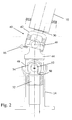
- Figure 1 shows an adjustable steering column made up of a first section 10 supporting a steering wheel 12 and a second section 14 which is secured to the vehicle chassis.
- the first section can pivot about pins 16 which connect two U-shaped brackets 20 and 22, welded respectively to the first and the second section of the steering column.
- a hydraulic spring and damper cylinder 18 extends between a bracket 24 welded to the lower section 14 of the steering column and a pin 26 mounted in the U-shaped bracket 20.
- the cylinder 18 supports the weight of the upper section 10 of the steering column and the steering wheel 12 during adjustment of their position and can be used to lock the section 10 of the steering column in any desired position.
- Movement of the steering wheel 12 towards the driver is limited by the pin 26 abutting the upper end of a plate 19 that is welded to the second section 14 of the steering column. Furthermore, a rearward extension 21 of the bracket 20 limits the movement of the steering wheel away from the driver by abutting the rear edge of the bracket 22.
- sections 10 and 14 of the steering column there are journalled two sections of a steering shaft connecting the steering wheel 12 to the vehicle steering mechanism.
- the two sections are connected to one another by means of a universal joint to allow them to pivot relative to one another.
- the pivot axis defined by the pins 16 coincides with the centre of the universal joint.
- the pivot axis defined by the pins 16 is intentionally moved to be further away from the line of action of the cylinder 18 than the centre of the universal joint in the steering shaft, as this allows the cylinder 18 to be mounted nearer to the steering column so as to take up less space. If the pin 16 is offset sufficiently from the centre of the universal joint, then is it possible for the cylinder 18 to be positioned alongside the steering column, instead of being in front of it.
- a Cardan joint 40 comprising two forks 42 and 44 and a cross 46 serves to couple the first section 30 of the steering shaft to the second section 32. If the axis of the pins 16 were arranged, as in the prior art, to coincide with the centre of the cross 46 there would be no movement of the cross 46 axially relative to the steering wheel and the steering mechanism. The fork 44 could therefore be permanently secured to the second section 32 of the steering shaft.
- the centre of the cross moves in a circle centred on the pivot axis of the pins 16 during adjustment of the position of the steering wheel.
- its second fork 44 is formed integrally with a link 48 in the form of a tube having two diametrically opposed axially extending slots 50 in its end.
- the slots 20 receive the ends of a pin 52 mounted in a bore extending transversely through a ball 54 formed at the end of the second section 32 of the steering shaft.
- the link 48 can tilt relative to the second section 32 of the steering shaft by pivoting about the pin 52 and it can also move axially by the pin 52 sliding in the slots 50.
Landscapes
- Engineering & Computer Science (AREA)
- Chemical & Material Sciences (AREA)
- Combustion & Propulsion (AREA)
- Transportation (AREA)
- Mechanical Engineering (AREA)
- Steering Controls (AREA)
- Steering Control In Accordance With Driving Conditions (AREA)
Claims (3)
- Lenksäule mit zwei Abschnitten (10, 14), die relativ zueinander verschwenkbar sind, um eine Einstellung der Position und des Neigungswinkels eines von einem ersten (10) der Abschnitte gehalterten Lenkrades (12) zu ermöglichen, und einer Lenkwelle, die in zwei Abschnitten (30, 32) gebildet ist, die in den jeweiligen Abschnitten (10, 14) der Lenksäule drehbar gelagert sind, und die miteinander mit Hilfe eines Universalgelenkes (40) verbunden sind, wobei das Universalgelenk (40) zwei Gabeln (42, 44) und ein Kreuz (46) umfasst und der Mittelpunkt des Universalgelenkes (40) gegenüber der Schwenkachse (16) der Abschnitte (10, 14) der Lenksäule versetzt ist und einer kreisförmigen Bahn, die auf der Schwenkachse (16) zentriert ist, folgt, wenn die Position des Lenkrades (12) geändert wird, wobei eine der Gabeln (42) fest mit einem ersten Abschnitt (30) der Lenkwelle verbunden ist, der mit dem Lenkrad (12) verbunden ist und die eine feste Länge aufweist, und
dadurch gekennzeichnet, dass:- ein zweiter Abschnitt (32) der Lenkwelle eine feste Position gegenüber der Schwenkachse (16) der Abschnitte (10, 14) aufweist; und- die andere der Gabeln (44) des Universalgelenkes (40) für eine Drehung mit dem zweiten Abschnitt (32) der Lenkwelle mit Hilfe eines Zwischengliedes (48) verbunden ist, das einstückig mit der zweiten Gabel ausgebildet ist; wobei das Zwischenglied (48) so betreibbar ist, dass es sich gegenüber dem zweiten Abschnitt (32) der Lenkwelle sowohl axial bewegt als auch verschwenkt, wenn die Position des Lenkrades (12) geändert wird. - Lenksäule nach Anspruch 1, dadurch gekennzeichnet, dass das Zwischenglied (48) ein Rohr umfasst, das an seinem Ende langestrecke Schlitze (50) aufweist, die einen Bolzen (52) aufnehmen, der seitlich von einer Kugel (54) vorspringt, die an dem Ende des zweiten Abschnittes der Lenkwelle angeordnet ist.
- Lenksäule nach Anspruch 1 oder 2, dadurch gekennzeichnet, dass ein Feder- und Dämpfungszylinder (18) zwischen den zwei Abschnitten (10, 14) der Lenksäule angeschlossen ist.
Applications Claiming Priority (2)
| Application Number | Priority Date | Filing Date | Title |
|---|---|---|---|
| ITTO20040159 | 2004-03-11 | ||
| IT000159A ITTO20040159A1 (it) | 2004-03-11 | 2004-03-11 | Piantone di sterzatura regolabile per un veicolo |
Publications (3)
| Publication Number | Publication Date |
|---|---|
| EP1574414A2 EP1574414A2 (de) | 2005-09-14 |
| EP1574414A3 EP1574414A3 (de) | 2005-10-19 |
| EP1574414B1 true EP1574414B1 (de) | 2008-02-13 |
Family
ID=34814972
Family Applications (1)
| Application Number | Title | Priority Date | Filing Date |
|---|---|---|---|
| EP05101250A Expired - Lifetime EP1574414B1 (de) | 2004-03-11 | 2005-02-18 | Verstellbare Kraftfahrzeuglenksäule |
Country Status (5)
| Country | Link |
|---|---|
| US (1) | US7603928B2 (de) |
| EP (1) | EP1574414B1 (de) |
| AT (1) | ATE385938T1 (de) |
| DE (1) | DE602005004679T2 (de) |
| IT (1) | ITTO20040159A1 (de) |
Families Citing this family (5)
| Publication number | Priority date | Publication date | Assignee | Title |
|---|---|---|---|---|
| US9254861B2 (en) * | 2012-05-25 | 2016-02-09 | Nsk Ltd. | Electric steering wheel position adjustment apparatus |
| JP6333191B2 (ja) * | 2015-02-13 | 2018-05-30 | 本田技研工業株式会社 | チルトステアリング装置 |
| JP6534178B1 (ja) * | 2018-05-28 | 2019-06-26 | 三菱ロジスネクスト株式会社 | ステアリング装置および荷役車両 |
| DE102022208597B4 (de) | 2022-08-18 | 2026-03-05 | Carl Zeiss Microscopy Gmbh | Vorrichtung zum Abbilden und Bearbeiten einer Probe mit einem fokussierten Teilchenstrahl |
| US12479291B1 (en) | 2024-11-07 | 2025-11-25 | Textron Inc. | Adjustable pedals |
Family Cites Families (17)
| Publication number | Priority date | Publication date | Assignee | Title |
|---|---|---|---|---|
| CH117915A (de) * | 1925-12-14 | 1927-01-17 | J Badertscher Otto | Bremseinrichtung für Kraftfahrzeuge mit Explosionsmotoren. |
| US3198030A (en) * | 1961-07-20 | 1965-08-03 | Ford Motor Co | Adjustable steering column |
| US4331003A (en) * | 1979-07-26 | 1982-05-25 | Barry Wright Corporation | Flexible coupling |
| JPS5663557A (en) * | 1979-10-26 | 1981-05-30 | Nissan Motor Co Ltd | Steering gear |
| US4392670A (en) * | 1981-02-27 | 1983-07-12 | Clark Equipment Company | Pivoted steering column for lift truck |
| US4946195A (en) * | 1988-03-08 | 1990-08-07 | Mazda Motor Corporation | Steering assembly supporting construction of a motor vehicle |
| US4856927A (en) * | 1988-06-06 | 1989-08-15 | The Torrington Company | Midpoint connection for intermediate shaft subassembly |
| US5036942A (en) * | 1990-08-14 | 1991-08-06 | Ford New Holland, Inc. | Rotatable operator control unlocking mechanism |
| DE4235588A1 (de) * | 1992-10-22 | 1994-04-28 | Stabilus Gmbh | Hydropneumatisches Verstellelement |
| DE4238732C1 (de) * | 1992-11-17 | 1994-02-17 | Lemfoerder Metallwaren Ag | Verstellbare Lenksäule für Kraftfahrzeuge |
| FR2699976B1 (fr) * | 1992-12-30 | 1996-07-26 | Castellon Melchor Daumal | Arbre telescopique. |
| DE19654273A1 (de) * | 1995-12-26 | 1997-07-03 | Aisin Seiki | Lenkradstellungseinstellvorrichtung für ein Fahrzeuglenksystem |
| DE69714945T2 (de) | 1996-11-12 | 2005-07-07 | Cnh Belgium N.V. | Vierfach verstellbare, sockelbodenbefestigte Lenksäule für einen Mähdrescher |
| DE19746790A1 (de) * | 1997-10-23 | 1999-05-06 | Daimler Chrysler Ag | Lenkanlage für ein Kraftfahrzeug |
| US6189405B1 (en) * | 1998-04-30 | 2001-02-20 | Kabushiki Kaisha Yamada Seisa Kusho | Position adjusting device for steering wheels |
| GB2349446A (en) | 1999-04-26 | 2000-11-01 | New Holland | Steering column aseembly |
| US6279953B1 (en) * | 1999-12-22 | 2001-08-28 | Trw Inc. | Flexible mount for an intermediate steering column |
-
2004
- 2004-03-11 IT IT000159A patent/ITTO20040159A1/it unknown
-
2005
- 2005-02-18 AT AT05101250T patent/ATE385938T1/de not_active IP Right Cessation
- 2005-02-18 EP EP05101250A patent/EP1574414B1/de not_active Expired - Lifetime
- 2005-02-18 DE DE602005004679T patent/DE602005004679T2/de not_active Expired - Lifetime
- 2005-03-10 US US11/077,473 patent/US7603928B2/en not_active Expired - Fee Related
Also Published As
| Publication number | Publication date |
|---|---|
| EP1574414A2 (de) | 2005-09-14 |
| DE602005004679D1 (de) | 2008-03-27 |
| EP1574414A3 (de) | 2005-10-19 |
| DE602005004679T2 (de) | 2008-06-05 |
| ATE385938T1 (de) | 2008-03-15 |
| US20050199086A1 (en) | 2005-09-15 |
| ITTO20040159A1 (it) | 2004-06-11 |
| US7603928B2 (en) | 2009-10-20 |
Similar Documents
| Publication | Publication Date | Title |
|---|---|---|
| CA3091237C (en) | All-terrain vehicle | |
| US7878517B2 (en) | Vehicle axle apparatus | |
| JP4305429B2 (ja) | インホイールサスペンション | |
| US5813684A (en) | Front wheel suspension for a motorcycle | |
| US11345395B2 (en) | Steering device | |
| US20080156571A1 (en) | Compact swing arm structure for a shaft-driven vehicle, and vehicle incorporating same | |
| US7841606B2 (en) | Rack steering motor vehicle | |
| US20150314826A1 (en) | Articulated two-wheeled vehicles | |
| JP2955549B2 (ja) | 四輪駆動車輛用ラックアンドピニオン式ステアリングシステム | |
| CN100369779C (zh) | 电动转向装置 | |
| CN1840404B (zh) | 转向手柄的位置调整装置 | |
| EP2025580A2 (de) | Lenkgruppe der Räder einer Achse eines Fahrzeugs | |
| US6327928B1 (en) | Steering column shifter assembly | |
| GB2107264A (en) | Vehicle steering mechanisms | |
| EP1574414B1 (de) | Verstellbare Kraftfahrzeuglenksäule | |
| US6647822B2 (en) | Vehicle shifter | |
| EP4656505A1 (de) | System zum lenken eines neigekraftfahrzeugs mit zwei vorderrädern | |
| GB2282997A (en) | Rack steering system for motor vehicles | |
| US4718686A (en) | Steering arrangement for motor vehicles | |
| KR101637577B1 (ko) | 차량의 스티어링 장치 | |
| US11548339B2 (en) | Relative guide device for a steering arrangement arranged on the wheel-carrier side | |
| US4354567A (en) | Rear axle suspension system for motor vehicles | |
| JP2005280678A (ja) | ステアリング装置 | |
| US5645299A (en) | Steering column support | |
| US12434758B2 (en) | Assembly for equipping motor vehicle with dual-steer capabilities |
Legal Events
| Date | Code | Title | Description |
|---|---|---|---|
| PUAI | Public reference made under article 153(3) epc to a published international application that has entered the european phase |
Free format text: ORIGINAL CODE: 0009012 |
|
| PUAL | Search report despatched |
Free format text: ORIGINAL CODE: 0009013 |
|
| AK | Designated contracting states |
Kind code of ref document: A2 Designated state(s): AT BE BG CH CY CZ DE DK EE ES FI FR GB GR HU IE IS IT LI LT LU MC NL PL PT RO SE SI SK TR |
|
| AX | Request for extension of the european patent |
Extension state: AL BA HR LV MK YU |
|
| AK | Designated contracting states |
Kind code of ref document: A3 Designated state(s): AT BE BG CH CY CZ DE DK EE ES FI FR GB GR HU IE IS IT LI LT LU MC NL PL PT RO SE SI SK TR |
|
| AX | Request for extension of the european patent |
Extension state: AL BA HR LV MK YU |
|
| 17P | Request for examination filed |
Effective date: 20060403 |
|
| AKX | Designation fees paid |
Designated state(s): AT BE BG CH CY CZ DE DK EE ES FI FR GB GR HU IE IS IT LI LT LU MC NL PL PT RO SE SI SK TR |
|
| 17Q | First examination report despatched |
Effective date: 20060725 |
|
| GRAP | Despatch of communication of intention to grant a patent |
Free format text: ORIGINAL CODE: EPIDOSNIGR1 |
|
| GRAS | Grant fee paid |
Free format text: ORIGINAL CODE: EPIDOSNIGR3 |
|
| GRAA | (expected) grant |
Free format text: ORIGINAL CODE: 0009210 |
|
| AK | Designated contracting states |
Kind code of ref document: B1 Designated state(s): AT BE BG CH CY CZ DE DK EE ES FI FR GB GR HU IE IS IT LI LT LU MC NL PL PT RO SE SI SK TR |
|
| REG | Reference to a national code |
Ref country code: GB Ref legal event code: FG4D |
|
| REG | Reference to a national code |
Ref country code: CH Ref legal event code: EP |
|
| REG | Reference to a national code |
Ref country code: IE Ref legal event code: FG4D |
|
| REF | Corresponds to: |
Ref document number: 602005004679 Country of ref document: DE Date of ref document: 20080327 Kind code of ref document: P |
|
| PG25 | Lapsed in a contracting state [announced via postgrant information from national office to epo] |
Ref country code: IS Free format text: LAPSE BECAUSE OF FAILURE TO SUBMIT A TRANSLATION OF THE DESCRIPTION OR TO PAY THE FEE WITHIN THE PRESCRIBED TIME-LIMIT Effective date: 20080613 Ref country code: FI Free format text: LAPSE BECAUSE OF FAILURE TO SUBMIT A TRANSLATION OF THE DESCRIPTION OR TO PAY THE FEE WITHIN THE PRESCRIBED TIME-LIMIT Effective date: 20080213 Ref country code: ES Free format text: LAPSE BECAUSE OF FAILURE TO SUBMIT A TRANSLATION OF THE DESCRIPTION OR TO PAY THE FEE WITHIN THE PRESCRIBED TIME-LIMIT Effective date: 20080524 |
|
| NLV1 | Nl: lapsed or annulled due to failure to fulfill the requirements of art. 29p and 29m of the patents act | ||
| ET | Fr: translation filed | ||
| PG25 | Lapsed in a contracting state [announced via postgrant information from national office to epo] |
Ref country code: AT Free format text: LAPSE BECAUSE OF FAILURE TO SUBMIT A TRANSLATION OF THE DESCRIPTION OR TO PAY THE FEE WITHIN THE PRESCRIBED TIME-LIMIT Effective date: 20080213 |
|
| PG25 | Lapsed in a contracting state [announced via postgrant information from national office to epo] |
Ref country code: BE Free format text: LAPSE BECAUSE OF FAILURE TO SUBMIT A TRANSLATION OF THE DESCRIPTION OR TO PAY THE FEE WITHIN THE PRESCRIBED TIME-LIMIT Effective date: 20080213 Ref country code: PL Free format text: LAPSE BECAUSE OF FAILURE TO SUBMIT A TRANSLATION OF THE DESCRIPTION OR TO PAY THE FEE WITHIN THE PRESCRIBED TIME-LIMIT Effective date: 20080213 Ref country code: SI Free format text: LAPSE BECAUSE OF FAILURE TO SUBMIT A TRANSLATION OF THE DESCRIPTION OR TO PAY THE FEE WITHIN THE PRESCRIBED TIME-LIMIT Effective date: 20080213 |
|
| PG25 | Lapsed in a contracting state [announced via postgrant information from national office to epo] |
Ref country code: SK Free format text: LAPSE BECAUSE OF FAILURE TO SUBMIT A TRANSLATION OF THE DESCRIPTION OR TO PAY THE FEE WITHIN THE PRESCRIBED TIME-LIMIT Effective date: 20080213 Ref country code: NL Free format text: LAPSE BECAUSE OF FAILURE TO SUBMIT A TRANSLATION OF THE DESCRIPTION OR TO PAY THE FEE WITHIN THE PRESCRIBED TIME-LIMIT Effective date: 20080213 Ref country code: DK Free format text: LAPSE BECAUSE OF FAILURE TO SUBMIT A TRANSLATION OF THE DESCRIPTION OR TO PAY THE FEE WITHIN THE PRESCRIBED TIME-LIMIT Effective date: 20080213 Ref country code: CZ Free format text: LAPSE BECAUSE OF FAILURE TO SUBMIT A TRANSLATION OF THE DESCRIPTION OR TO PAY THE FEE WITHIN THE PRESCRIBED TIME-LIMIT Effective date: 20080213 Ref country code: PT Free format text: LAPSE BECAUSE OF FAILURE TO SUBMIT A TRANSLATION OF THE DESCRIPTION OR TO PAY THE FEE WITHIN THE PRESCRIBED TIME-LIMIT Effective date: 20080714 Ref country code: SE Free format text: LAPSE BECAUSE OF FAILURE TO SUBMIT A TRANSLATION OF THE DESCRIPTION OR TO PAY THE FEE WITHIN THE PRESCRIBED TIME-LIMIT Effective date: 20080513 Ref country code: MC Free format text: LAPSE BECAUSE OF NON-PAYMENT OF DUE FEES Effective date: 20080228 |
|
| PG25 | Lapsed in a contracting state [announced via postgrant information from national office to epo] |
Ref country code: RO Free format text: LAPSE BECAUSE OF FAILURE TO SUBMIT A TRANSLATION OF THE DESCRIPTION OR TO PAY THE FEE WITHIN THE PRESCRIBED TIME-LIMIT Effective date: 20080213 |
|
| PLBE | No opposition filed within time limit |
Free format text: ORIGINAL CODE: 0009261 |
|
| STAA | Information on the status of an ep patent application or granted ep patent |
Free format text: STATUS: NO OPPOSITION FILED WITHIN TIME LIMIT |
|
| 26N | No opposition filed |
Effective date: 20081114 |
|
| PG25 | Lapsed in a contracting state [announced via postgrant information from national office to epo] |
Ref country code: EE Free format text: LAPSE BECAUSE OF FAILURE TO SUBMIT A TRANSLATION OF THE DESCRIPTION OR TO PAY THE FEE WITHIN THE PRESCRIBED TIME-LIMIT Effective date: 20080213 Ref country code: IE Free format text: LAPSE BECAUSE OF NON-PAYMENT OF DUE FEES Effective date: 20080218 Ref country code: LT Free format text: LAPSE BECAUSE OF FAILURE TO SUBMIT A TRANSLATION OF THE DESCRIPTION OR TO PAY THE FEE WITHIN THE PRESCRIBED TIME-LIMIT Effective date: 20080213 |
|
| PG25 | Lapsed in a contracting state [announced via postgrant information from national office to epo] |
Ref country code: BG Free format text: LAPSE BECAUSE OF FAILURE TO SUBMIT A TRANSLATION OF THE DESCRIPTION OR TO PAY THE FEE WITHIN THE PRESCRIBED TIME-LIMIT Effective date: 20080513 |
|
| PG25 | Lapsed in a contracting state [announced via postgrant information from national office to epo] |
Ref country code: CY Free format text: LAPSE BECAUSE OF FAILURE TO SUBMIT A TRANSLATION OF THE DESCRIPTION OR TO PAY THE FEE WITHIN THE PRESCRIBED TIME-LIMIT Effective date: 20080213 |
|
| REG | Reference to a national code |
Ref country code: CH Ref legal event code: PL |
|
| PG25 | Lapsed in a contracting state [announced via postgrant information from national office to epo] |
Ref country code: LI Free format text: LAPSE BECAUSE OF NON-PAYMENT OF DUE FEES Effective date: 20090228 Ref country code: CH Free format text: LAPSE BECAUSE OF NON-PAYMENT OF DUE FEES Effective date: 20090228 |
|
| PG25 | Lapsed in a contracting state [announced via postgrant information from national office to epo] |
Ref country code: LU Free format text: LAPSE BECAUSE OF NON-PAYMENT OF DUE FEES Effective date: 20080218 Ref country code: HU Free format text: LAPSE BECAUSE OF FAILURE TO SUBMIT A TRANSLATION OF THE DESCRIPTION OR TO PAY THE FEE WITHIN THE PRESCRIBED TIME-LIMIT Effective date: 20080814 |
|
| PG25 | Lapsed in a contracting state [announced via postgrant information from national office to epo] |
Ref country code: TR Free format text: LAPSE BECAUSE OF FAILURE TO SUBMIT A TRANSLATION OF THE DESCRIPTION OR TO PAY THE FEE WITHIN THE PRESCRIBED TIME-LIMIT Effective date: 20080213 |
|
| PG25 | Lapsed in a contracting state [announced via postgrant information from national office to epo] |
Ref country code: GR Free format text: LAPSE BECAUSE OF FAILURE TO SUBMIT A TRANSLATION OF THE DESCRIPTION OR TO PAY THE FEE WITHIN THE PRESCRIBED TIME-LIMIT Effective date: 20080514 |
|
| REG | Reference to a national code |
Ref country code: DE Ref legal event code: R082 Ref document number: 602005004679 Country of ref document: DE Representative=s name: PATENTANWAELTE WALLACH, KOCH & PARTNER, DE |
|
| REG | Reference to a national code |
Ref country code: DE Ref legal event code: R082 Ref document number: 602005004679 Country of ref document: DE Representative=s name: PATENTANWAELTE WALLACH, KOCH & PARTNER, DE Effective date: 20140623 Ref country code: DE Ref legal event code: R081 Ref document number: 602005004679 Country of ref document: DE Owner name: CNH INDUSTRIAL ITALIA S.P.A., IT Free format text: FORMER OWNER: CNH ITALIA S.P.A., MODENA, IT Effective date: 20140623 Ref country code: DE Ref legal event code: R082 Ref document number: 602005004679 Country of ref document: DE Representative=s name: PATENTANWAELTE WALLACH, KOCH, DR. HAIBACH, FEL, DE Effective date: 20140623 |
|
| REG | Reference to a national code |
Ref country code: FR Ref legal event code: CD Owner name: CNH INDUSTRIAL ITALIA S.P.A. Effective date: 20150313 |
|
| REG | Reference to a national code |
Ref country code: FR Ref legal event code: PLFP Year of fee payment: 12 |
|
| REG | Reference to a national code |
Ref country code: FR Ref legal event code: PLFP Year of fee payment: 13 |
|
| REG | Reference to a national code |
Ref country code: FR Ref legal event code: PLFP Year of fee payment: 14 |
|
| PGFP | Annual fee paid to national office [announced via postgrant information from national office to epo] |
Ref country code: GB Payment date: 20200219 Year of fee payment: 16 |
|
| PGFP | Annual fee paid to national office [announced via postgrant information from national office to epo] |
Ref country code: FR Payment date: 20200219 Year of fee payment: 16 |
|
| REG | Reference to a national code |
Ref country code: DE Ref legal event code: R082 Ref document number: 602005004679 Country of ref document: DE Representative=s name: MEISSNER BOLTE PATENTANWAELTE RECHTSANWAELTE P, DE |
|
| REG | Reference to a national code |
Ref country code: DE Ref legal event code: R084 Ref document number: 602005004679 Country of ref document: DE |
|
| GBPC | Gb: european patent ceased through non-payment of renewal fee |
Effective date: 20210218 |
|
| PG25 | Lapsed in a contracting state [announced via postgrant information from national office to epo] |
Ref country code: GB Free format text: LAPSE BECAUSE OF NON-PAYMENT OF DUE FEES Effective date: 20210218 Ref country code: FR Free format text: LAPSE BECAUSE OF NON-PAYMENT OF DUE FEES Effective date: 20210228 |
|
| PGFP | Annual fee paid to national office [announced via postgrant information from national office to epo] |
Ref country code: IT Payment date: 20230210 Year of fee payment: 19 |
|
| PGFP | Annual fee paid to national office [announced via postgrant information from national office to epo] |
Ref country code: DE Payment date: 20240228 Year of fee payment: 20 |
|
| REG | Reference to a national code |
Ref country code: DE Ref legal event code: R071 Ref document number: 602005004679 Country of ref document: DE |