EP1574413B1 - Bar assembly, in particular testing assembly for switch tongues - Google Patents
Bar assembly, in particular testing assembly for switch tongues Download PDFInfo
- Publication number
- EP1574413B1 EP1574413B1 EP05090058A EP05090058A EP1574413B1 EP 1574413 B1 EP1574413 B1 EP 1574413B1 EP 05090058 A EP05090058 A EP 05090058A EP 05090058 A EP05090058 A EP 05090058A EP 1574413 B1 EP1574413 B1 EP 1574413B1
- Authority
- EP
- European Patent Office
- Prior art keywords
- bar
- intermediate piece
- piece
- assembly
- closure
- Prior art date
- Legal status (The legal status is an assumption and is not a legal conclusion. Google has not performed a legal analysis and makes no representation as to the accuracy of the status listed.)
- Not-in-force
Links
- 210000002105 tongue Anatomy 0.000 title claims 2
- 238000000465 moulding Methods 0.000 claims description 16
- 238000007789 sealing Methods 0.000 abstract 3
- 125000006850 spacer group Chemical group 0.000 abstract 2
- 238000006073 displacement reaction Methods 0.000 description 2
- 238000000151 deposition Methods 0.000 description 1
Images

Classifications
-
- B—PERFORMING OPERATIONS; TRANSPORTING
- B61—RAILWAYS
- B61L—GUIDING RAILWAY TRAFFIC; ENSURING THE SAFETY OF RAILWAY TRAFFIC
- B61L5/00—Local operating mechanisms for points or track-mounted scotch-blocks; Visible or audible signals; Local operating mechanisms for visible or audible signals
- B61L5/10—Locking mechanisms for points; Means for indicating the setting of points
Definitions
- the invention relates to a rod arrangement, in particular tongue tester arrangement for switches, according to the preamble of claim 1.
- Tongue examiners are used to mechanically scan the actual state of the switch, ie the current position of the two switch blades relative to the jaw rails and to generate a test signal, can be reliably determined by means of whether the switch has been converted correctly and whether the fitting and the depositing switch blade are in their respective predetermined end position.
- the scholarerstangen extend substantially transverse to the switch blades and are moved when switching the switch in its longitudinal direction. The positions of the scholarerstangen be detected by means of electromechanical transducers, for example by limit switches, which are actuated by a shift finger of the strigerstange.
- the Zaerstange is usually divided into two non-rotatable rod pieces, which are connected together for the purpose of length adjustment via an intermediate piece.
- a union nut is used as an intermediate piece, on the one hand a left-hand thread and on the other hand a right-hand thread has, which engage in corresponding threaded ends of the rod pieces.
- the cap nut By rotation of the cap nut, the rod pieces are either moved toward each other or away from each other, so that in this way the distance between the rod pieces and thus the total length of the tongue tester assembly is adjustable. It must be ensured that an unintentional length adjustment, for example, by accidental or vibration-induced effect on the intermediate piece, is virtually excluded.
- a locking mechanism in which a sleeve is positively pushed onto a rod piece and the intermediate piece.
- the sleeve is biased in the direction of displacement and must be pushed back against this bias for the purpose of adjusting the intermediate piece, with the sleeve thereafter automatically pushes over the intermediate piece and causes the lock.
- the invention has for its object to provide a rod assembly of the generic type, in which the length adjustment, especially in terms of wear and handling is simplified.
- the object is achieved with the features of claim 1. Due to the pivotable closure molding, whose free end is designed to fix the position of the intermediate piece relative to the two fixed rod pieces, resulting in a simple manner a wear-resistant and easily negotiable length adjustment of the rod assembly. A provided according to the prior art bias of the locking element, which counteracts during theChinanverstellreaes by exertion must be deleted. As a result, a very sensitive length adjustment is possible without much effort. After adjustment, the closure molding must be pivoted only by the fitter in a final handle in the locking position. The safety function, which is achieved in the prior art by the bias of the sliding sleeve is integrated into the closure molding itself. Because of the hinge fastening of the closure molding on one of the two rod pieces, the position of the closure molding is predetermined with respect to the intermediate piece for each length adjustment of the rod assembly. An axial displacement of the locking element is not possible in contrast to the prior art.
- the free end of the closure molding according to claim 2 is formed as a clamp which engages around a preferably hexagonal outer contour of the intermediate piece form fit.
- the clip is provided according to claim 3 with two spring arms, which have mutually facing spreadable retaining ends.
- the tongue checker arrangement shown in FIG. 1 essentially comprises a first rod piece 1, a second rod piece 2 arranged axially and non-rotatably therewith, an intermediate piece 3 for spacing adjustment between the two rod pieces 1 and 2 and a closure molding 4 for fixing the position of the intermediate piece 3 relative to the latter
- the intermediate piece 3 is screwed in the manner of a union nut with the two opposite ends 5 and 6 of the rod pieces 1 and 2.
- the intermediate piece 3 is equipped with a right-hand thread 7 and a left-hand thread 8.
- the closure molding 4 is pivotally mounted on the rod piece 1 via a radial joint 9.
- the closure mold part 4 is shown in locked pivot position, wherein a clip 10 at the free end of the closure mold part 4, the preferably hexagonal outer contour of the intermediate piece 3 engages positively.
- the set length x is thus secured, since the clamp 10 prevents the intermediate piece 3 from being inadvertently twisted by vibrations or other mechanical influences.
- the closure molding 4, as shown in Figure 2 pivoted away from the clip holder.
- the swivel angle can be for example 90 °.
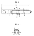
- FIG 3 illustrates the new length x - ⁇ when the closure mold part is pivoted back.
- the pivoting back of the closure mold part 4 virtually causes the clamp 10 of the closure mold part 4 to engage in place in the clamped position
- the bracket 10 is equipped with two spring arms 11 and 12, which fix the intermediate piece 3 by means of spreadable retaining ends 13 and 14 the rotation.
Landscapes
- Engineering & Computer Science (AREA)
- Mechanical Engineering (AREA)
- Clamps And Clips (AREA)
- Paper (AREA)
- Operation Control Of Excavators (AREA)
- Measurement Of The Respiration, Hearing Ability, Form, And Blood Characteristics Of Living Organisms (AREA)
- Measuring Pulse, Heart Rate, Blood Pressure Or Blood Flow (AREA)
- Measuring And Recording Apparatus For Diagnosis (AREA)
- Transmission Devices (AREA)
- Control Of Resistance Heating (AREA)
- Push-Button Switches (AREA)
- Train Traffic Observation, Control, And Security (AREA)
Abstract
Description
Die Erfindung betrifft eine Stangenanordnung, insbesondere Zungenprüferanordnung für Weichen, gemäß dem Oberbegriff des Anspruchs 1.The invention relates to a rod arrangement, in particular tongue tester arrangement for switches, according to the preamble of claim 1.
Die nachfolgenden Erläuterungen beziehen sich im Wesentlichen auf eine Zungenprüferanordnung für Weichen für Schienenfahrzeuge, ohne dass der Schutzbereich auf diese spezielle Anwendung beschränkt sein soll.The following explanations essentially relate to a tongue checker arrangement for switches for rail vehicles, without the scope of protection being restricted to this particular application.
Zungenprüfer dienen dazu, den Ist-Zustand der Weiche, d. h. die aktuelle Lage der beiden Weichenzungen relativ zu den Backenschienen, mechanisch abzutasten und ein Prüfsignal zu erzeugen, anhand dessen zuverlässig festgestellt werden kann, ob die Weiche korrekt umgestellt wurde und ob sich die anliegende und die ablegende Weichenzunge in ihrer jeweiligen vorgegebenen Endlage befinden. Die Prüferstangen erstrecken sich im Wesentlichen quer zu den Weichenzungen und werden beim Umstellen der Weiche in ihrer Längsrichtung verschoben. Die Positionen der Prüferstangen werden mit Hilfe von elektromechanischen Wandlern, beispielsweise durch Endschalter, erfasst, die durch einen Schaltfinger der Prüferstange betätigt werden. Da die Zungenp0rüferanordnung für verschiedene Montageorte mit unterschiedlichem Abstand zum Weichenzungenende geeignet sein muss, ist die Prüferstange üblicherweise in zwei drehfeste Stangenstücke unterteilt, die zwecks Längeneinstellung über ein Zwischenstück miteinander verbinden sind. Häufig wird als Zwischenstück eine Überwurfmutter verwendet, die einerseits ein Linksgewinde und andererseits ein Rechtsgewinde aufweist, welche in entsprechende Gewindeenden der Stangenstücke eingreifen. Durch Drehung der Überwurfmutter werden die Stangenstücken entweder aufeinander zubewegt oder voneinander entfernt, so dass auf diese Weise der Abstand zwischen den Stangenstücken und damit die Gesamtlänge der Zungenprüferanordnung einstellbar ist. Dabei muss gewährleistet sein, dass eine unbeabsichtigte Längenverstellung, beispielsweise durch zufällige oder erschütterungsbedingte Einwirkung auf das Zwischenstück, quasi ausgeschlossen ist.Tongue examiners are used to mechanically scan the actual state of the switch, ie the current position of the two switch blades relative to the jaw rails and to generate a test signal, can be reliably determined by means of whether the switch has been converted correctly and whether the fitting and the depositing switch blade are in their respective predetermined end position. The Prüferstangen extend substantially transverse to the switch blades and are moved when switching the switch in its longitudinal direction. The positions of the Prüferstangen be detected by means of electromechanical transducers, for example by limit switches, which are actuated by a shift finger of the Prüferstange. Since the Zungenp0rüferanordnung must be suitable for different locations with different distances to the switch blade end, the Prüferstange is usually divided into two non-rotatable rod pieces, which are connected together for the purpose of length adjustment via an intermediate piece. Often, a union nut is used as an intermediate piece, on the one hand a left-hand thread and on the other hand a right-hand thread has, which engage in corresponding threaded ends of the rod pieces. By rotation of the cap nut, the rod pieces are either moved toward each other or away from each other, so that in this way the distance between the rod pieces and thus the total length of the tongue tester assembly is adjustable. It must be ensured that an unintentional length adjustment, for example, by accidental or vibration-induced effect on the intermediate piece, is virtually excluded.
Aus der DE 198 40 328 C1 ist ein Verriegelungsmechanismus bekannt, bei dem eine Hülse formschlüssig auf ein Stangenstück und das Zwischenstück aufgeschoben wird. Die Hülse steht in Verschieberichtung unter Vorspannung und muss gegen diese Vorspannung zum Zwecke der Verstellung des Zwischenstückes zurückgeschoben werden, wobei sich die Hülse hernach selbsttätig über das Zwischenstück schiebt und die Verriegelung bewirkt.From DE 198 40 328 C1, a locking mechanism is known in which a sleeve is positively pushed onto a rod piece and the intermediate piece. The sleeve is biased in the direction of displacement and must be pushed back against this bias for the purpose of adjusting the intermediate piece, with the sleeve thereafter automatically pushes over the intermediate piece and causes the lock.
Der Erfindung liegt die Aufgabe zugrunde, eine Stangenanordnung der gattungsgemäßen Art anzugeben, bei der die Längeneinstellung, insbesondere hinsichtlich Verschleiß und Handling vereinfacht ist.The invention has for its object to provide a rod assembly of the generic type, in which the length adjustment, especially in terms of wear and handling is simplified.
Erfindungsgemäß wird die Aufgabe mit den Merkmalen des Anspruchs 1 gelöst. Durch das schwenkbare Verschlussformteil, dessen freies Ende zur Lagefixierung des Zwischenstückes gegenüber den beiden festen Stangenstücken ausgebildet ist, ergibt sich in einfacher Weise eine verschleißresistente und gut händelbare Längenverstellung der Stangenanordnung. Eine nach dem Stand der Technik vorgesehene Vorspannung des Verriegelungselementes, der während des Längenverstellprozesses durch Kraftanstrengung entgegengewirkt werden muss, entfällt. Dadurch ist ohne größere Kraftanstrengung eine sehr feinfühlige Längenverstellung möglich. Nach dem Verstellvorgang muss das Verschlussformteil nur noch vom Monteur in einem abschließenden Handgriff in die Verriegelungsposition geschwenkt werden. Die Sicherheitsfunktion, die nach dem Stand der Technik durch die Vorspannung der Schiebehülse erreicht wird, ist in das Verschlussformteil selbst integriert. Wegen der Gelenkbefestigung des Verschlussformteils an einem der beiden Stangenstücke ist die Lage des Verschlussformteils gegenüber dem Zwischenstück für jede Längeneinstellung der Stangenanordnung vorgegeben. Eine Axialverschiebung des Verriegelungselementes ist im Gegensatz zum Stand der Technik nicht möglich.According to the invention the object is achieved with the features of claim 1. Due to the pivotable closure molding, whose free end is designed to fix the position of the intermediate piece relative to the two fixed rod pieces, resulting in a simple manner a wear-resistant and easily negotiable length adjustment of the rod assembly. A provided according to the prior art bias of the locking element, which counteracts during the Längenverstellprozesses by exertion must be deleted. As a result, a very sensitive length adjustment is possible without much effort. After adjustment, the closure molding must be pivoted only by the fitter in a final handle in the locking position. The safety function, which is achieved in the prior art by the bias of the sliding sleeve is integrated into the closure molding itself. Because of the hinge fastening of the closure molding on one of the two rod pieces, the position of the closure molding is predetermined with respect to the intermediate piece for each length adjustment of the rod assembly. An axial displacement of the locking element is not possible in contrast to the prior art.
Um zu verhindern, dass sich das Zwischenstück unter dem Verschlussformteil drehen kann und damit unbeabsichtigt der Abstand zwischen den Stangenstücken verändert werden kann, ist das freie Ende des Verschlussformteils gemäß Anspruch 2 als Klammer ausgebildet, welche eine vorzugsweise sechskantige Außenkontur des Zwischenstücks formschlüssig umgreift.In order to prevent that the intermediate piece can rotate under the closure molding and thus inadvertently the distance between the rod pieces can be changed, the free end of the closure molding according to
Vorzugsweise ist die Klammer gemäß Anspruch 3 mit zwei Federarmen versehen, welche einander zugewandte aufspreizbare Festhalteenden aufweisen.Preferably, the clip is provided according to
Die Erfindung wird nachfolgend anhand figürlicher Darstellungen näher erläutert. Es zeigen:
- Figur 1
- eine Zungenprüferanordnung mit verriegeltem Verschlussformteil bei eingestellter Länge x,
Figur 2- die Zungenprüferanordnung mit entriegeltem Verschlussformteil,
Figur 3- die Zungenprüferanordnung mit verriegeltem Verschlussformteil bei eingestellter Länge x - δ und
Figur 4- einen Querschnitt entlang der Linie A-A gemäß
Figur 3.
- FIG. 1
- a tongue tester arrangement with locked closure molding at set length x,
- FIG. 2
- the tongue tester assembly with unlocked closure molding,
- FIG. 3
- the tongue tester assembly with locked closure molding at set length x - δ and
- FIG. 4
- a cross section along the line AA of Figure 3.
Die in Figur 1 dargestellte Zungenprüferanordnung besteht im Wesentlichen aus einem ersten Stangenstück 1, einem axial und drehfest zu diesem angeordneten zweiten Stangenstück 2, einem Zwischenstück 3 zur Abstandseinstellung zwischen den beiden Stangenstücken 1 und 2 sowie einem Verschlussformteil 4 zur Lagefixierung des Zwischenstückes 3 relativ zu dem ersten Stangenstück 1. Das Zwischenstück 3 ist nach Art einer Überwurfmutter mit den beiden sich gegenüberliegenden Enden 5 und 6 der Stangenstücke 1 und 2 verschraubt. Dazu ist das Zwischenstück 3 mit einem Rechtsgewinde 7 und einem Linksgewinde 8 ausgestattet. Das Verschlussformteil 4 ist über ein radiales Gelenk 9 an dem Stangenstück 1 schwenkbar befestigt. In Figur 1 ist das Verschlussformteil 4 in verriegelter Schwenklage dargestellt, wobei eine Klammer 10 am freien Ende des Verschlussformteils 4 die vorzugsweise sechskantige Außenkontur des Zwischenstücks 3 formschlüssig umgreift. Die eingestellte Länge x ist somit gesichert, da die Klammer 10 verhindert, dass das Zwischenstück 3 durch Erschütterungen oder andere mechanische Einflüsse unbeabsichtigt verdreht werden kann. Um eine andere Länge, beispielsweise x - δ einzustellen, wird das Verschlussformteil 4, wie in Figur 2 dargestellt, von der Klammerhalterung weggeschwenkt. Der Schwenkwinkel kann beispielsweise 90° betragen. Durch Drehung des Zwischenstücks 3 in einer bestimmten Richtung werden die Enden 5 und 6 der Stangenstücke 1 und 2 mit Hilfe des Linksgewindes 8 und des Rechtsgewindes 7 des Zwischenstückes dichter aneinander herangezogen. Die neue Länge x - δ bei zurückgeschwenkten Verschlussformteil veranschaulicht Figur 3. Das Zurückschwenken des Verschlussformteils 4 bewirkt quasi ein Einrasten der Klammer 10 des Verschlussformteils 4 in Umklammerung der sechskantigen Außenkontur des Zwischenstücks 3. Wie Figur 4 zeigt, ist die Klammer 10 dazu mit zwei Federarmen 11 und 12 ausgestattet, welche mittels aufspreizbarer Festhalteenden 13 und 14 das Zwischenstück 3 drehsicher fixieren. The tongue checker arrangement shown in FIG. 1 essentially comprises a first rod piece 1, a
Claims (3)
- Bar assembly, in particular testing assembly for switch tongues, having two bar pieces (1, 2) which are arranged axially and such that they are rotationally fixed one to the other and which are mutually connected in a spacing-adjustable manner by an intermediate piece (3), in particular a cap nut or a threaded rod having oppositely directed threaded ends (7, 8) assigned to the bar pieces (1, 2), characterized in that a closure moulding (4) is provided, which is radially attached to a first bar piece (1) and is pivotable, the free end of the closure moulding (4) being lockable with the intermediate piece (3) and/or the second bar piece (2), in particular resiliently.
- Bar assembly according to Claim 1, characterized in that the free end of the closure moulding (4) is configured as a clamp (10) resiliently embracing a polygonal, in particular hexagonal, outer contour of the intermediate piece (3) and/or of the second bar piece (2).
- Bar assembly according to Claim 2, characterized in that the clamp (10) has two spring arms (11, 12) having mutually facing, expandable retaining ends (13, 14).
Applications Claiming Priority (2)
| Application Number | Priority Date | Filing Date | Title |
|---|---|---|---|
| DE102004013498 | 2004-03-12 | ||
| DE102004013498A DE102004013498B4 (en) | 2004-03-12 | 2004-03-12 | Tongue detector arrangement for switches |
Publications (2)
| Publication Number | Publication Date |
|---|---|
| EP1574413A1 EP1574413A1 (en) | 2005-09-14 |
| EP1574413B1 true EP1574413B1 (en) | 2006-05-31 |
Family
ID=34813717
Family Applications (1)
| Application Number | Title | Priority Date | Filing Date |
|---|---|---|---|
| EP05090058A Not-in-force EP1574413B1 (en) | 2004-03-12 | 2005-03-08 | Bar assembly, in particular testing assembly for switch tongues |
Country Status (6)
| Country | Link |
|---|---|
| EP (1) | EP1574413B1 (en) |
| AT (1) | ATE327931T1 (en) |
| DE (2) | DE102004013498B4 (en) |
| DK (1) | DK1574413T3 (en) |
| ES (1) | ES2264559T3 (en) |
| NO (1) | NO330881B1 (en) |
Families Citing this family (1)
| Publication number | Priority date | Publication date | Assignee | Title |
|---|---|---|---|---|
| DK3412535T3 (en) * | 2017-06-08 | 2020-03-02 | Alstom Transp Tech | Changing machine for a railway |
Family Cites Families (7)
| Publication number | Priority date | Publication date | Assignee | Title |
|---|---|---|---|---|
| GB190924120A (en) * | 1909-10-20 | 1910-01-27 | William Samuel Laycock | Improvements in and relating to Disconnectible Hose Couplings for Railway and like Vehicles. |
| GB146797A (en) * | 1919-07-15 | 1920-07-15 | Edward Sydney Luard | Improvements in or relating to couplings for flexible pipes |
| DE703708C (en) * | 1939-03-31 | 1941-03-14 | E H Dr Phil H C Ernst Heinkel | Securing for union nuts |
| DE964873C (en) * | 1955-06-30 | 1957-05-29 | Krauss Maffei Ag | Storage and security for an undivided horizontal brake pull rod |
| GB2217927B (en) * | 1988-03-12 | 1992-04-01 | Electronic Components Ltd | Bayonet coupling connector |
| DE19840328C1 (en) * | 1998-09-04 | 2000-03-23 | Ruhrtaler Gesenkschmiede F W W | Points testing rod has end pieces connected by tube with polygonal section locking sleeve |
| DE10321309B4 (en) * | 2002-06-24 | 2004-11-11 | Berlin Heart Ag | Device for connecting a cannula made of flexible material to a tube |
-
2004
- 2004-03-12 DE DE102004013498A patent/DE102004013498B4/en not_active Expired - Fee Related
-
2005
- 2005-03-04 NO NO20051174A patent/NO330881B1/en not_active IP Right Cessation
- 2005-03-08 AT AT05090058T patent/ATE327931T1/en active
- 2005-03-08 DK DK05090058T patent/DK1574413T3/en active
- 2005-03-08 ES ES05090058T patent/ES2264559T3/en active Active
- 2005-03-08 DE DE502005000014T patent/DE502005000014D1/en not_active Expired - Lifetime
- 2005-03-08 EP EP05090058A patent/EP1574413B1/en not_active Not-in-force
Also Published As
| Publication number | Publication date |
|---|---|
| ES2264559T3 (en) | 2007-01-01 |
| EP1574413A1 (en) | 2005-09-14 |
| NO20051174L (en) | 2005-09-13 |
| DK1574413T3 (en) | 2006-10-02 |
| DE102004013498B4 (en) | 2006-08-24 |
| DE102004013498A1 (en) | 2005-09-29 |
| DE502005000014D1 (en) | 2006-07-06 |
| NO20051174D0 (en) | 2005-03-04 |
| NO330881B1 (en) | 2011-08-08 |
| ATE327931T1 (en) | 2006-06-15 |
Similar Documents
| Publication | Publication Date | Title |
|---|---|---|
| DE2934922C2 (en) | Attachment for a gear housing of a rack and pinion steering | |
| DE2239853C3 (en) | Holding device for exterior rearview mirrors of motor vehicles or the like | |
| EP1887557A2 (en) | Conga stand | |
| EP1884382A1 (en) | Oscillation suppressor with mounting | |
| EP2197692B1 (en) | Pair of compasses having a joint with a locking device | |
| EP3676132A1 (en) | Spring element for fastening an air bag module to a vehicle steering wheel, and steering wheel assembly comprising such a spring element | |
| EP0342350B1 (en) | Automotive vehicle steering column, manually adjustable in height | |
| DE102010022513B4 (en) | Locking system for a vehicle steering system | |
| EP1574413B1 (en) | Bar assembly, in particular testing assembly for switch tongues | |
| WO2005042888A1 (en) | Track clamping holder for fixing tracks of sliding door systems | |
| DE102015116727A1 (en) | Device for holding a pipe in a beverage bottling plant | |
| DE102006028570B4 (en) | Striker assembly for a motor vehicle | |
| DE202008004420U1 (en) | Rollover protection system for motor vehicles | |
| DE202010010698U1 (en) | Device for end position testing of moving parts of a rail switch | |
| DE102011083358B4 (en) | Clamping device, in particular for a roof rack of a motor vehicle | |
| DE19701371B4 (en) | Device for fastening a spare wheel in a spare wheel well of a motor vehicle | |
| DE102005046325B4 (en) | Device for attaching a wiper functional unit to a wiper shaft | |
| EP1410971B1 (en) | Steering column | |
| DE8816665U1 (en) | Height adjustment device for a fitting of a seat belt restraint system in motor vehicles | |
| EP2578781B1 (en) | Locking device with rotary latch bolt | |
| DE19840328C1 (en) | Points testing rod has end pieces connected by tube with polygonal section locking sleeve | |
| EP0774028B1 (en) | Link joint | |
| EP2202414B1 (en) | Device for holding an object to be measured in a reference point | |
| DE102019008731A1 (en) | Screw arrangement | |
| DE102018123538A1 (en) | Adjustable steering column |
Legal Events
| Date | Code | Title | Description |
|---|---|---|---|
| PUAI | Public reference made under article 153(3) epc to a published international application that has entered the european phase |
Free format text: ORIGINAL CODE: 0009012 |
|
| AK | Designated contracting states |
Kind code of ref document: A1 Designated state(s): AT BE BG CH CY CZ DE DK EE ES FI FR GB GR HU IE IS IT LI LT LU MC NL PL PT RO SE SI SK TR |
|
| AX | Request for extension of the european patent |
Extension state: AL BA HR LV MK YU |
|
| GRAP | Despatch of communication of intention to grant a patent |
Free format text: ORIGINAL CODE: EPIDOSNIGR1 |
|
| 17P | Request for examination filed |
Effective date: 20051010 |
|
| GRAS | Grant fee paid |
Free format text: ORIGINAL CODE: EPIDOSNIGR3 |
|
| GRAA | (expected) grant |
Free format text: ORIGINAL CODE: 0009210 |
|
| AK | Designated contracting states |
Kind code of ref document: B1 Designated state(s): AT BE BG CH CY CZ DE DK EE ES FI FR GB GR HU IE IS IT LI LT LU MC NL PL PT RO SE SI SK TR |
|
| AKX | Designation fees paid |
Designated state(s): AT BE BG CH CY CZ DE DK EE ES FI FR GB GR HU IE IS IT LI LT LU MC NL PL PT RO SE SI SK TR |
|
| PG25 | Lapsed in a contracting state [announced via postgrant information from national office to epo] |
Ref country code: IT Free format text: LAPSE BECAUSE OF FAILURE TO SUBMIT A TRANSLATION OF THE DESCRIPTION OR TO PAY THE FEE WITHIN THE PRESCRIBED TIME-LIMIT;WARNING: LAPSES OF ITALIAN PATENTS WITH EFFECTIVE DATE BEFORE 2007 MAY HAVE OCCURRED AT ANY TIME BEFORE 2007. THE CORRECT EFFECTIVE DATE MAY BE DIFFERENT FROM THE ONE RECORDED. Effective date: 20060531 Ref country code: IE Free format text: LAPSE BECAUSE OF FAILURE TO SUBMIT A TRANSLATION OF THE DESCRIPTION OR TO PAY THE FEE WITHIN THE PRESCRIBED TIME-LIMIT Effective date: 20060531 Ref country code: CZ Free format text: LAPSE BECAUSE OF FAILURE TO SUBMIT A TRANSLATION OF THE DESCRIPTION OR TO PAY THE FEE WITHIN THE PRESCRIBED TIME-LIMIT Effective date: 20060531 Ref country code: RO Free format text: LAPSE BECAUSE OF FAILURE TO SUBMIT A TRANSLATION OF THE DESCRIPTION OR TO PAY THE FEE WITHIN THE PRESCRIBED TIME-LIMIT Effective date: 20060531 Ref country code: LT Free format text: LAPSE BECAUSE OF FAILURE TO SUBMIT A TRANSLATION OF THE DESCRIPTION OR TO PAY THE FEE WITHIN THE PRESCRIBED TIME-LIMIT Effective date: 20060531 Ref country code: GB Free format text: LAPSE BECAUSE OF FAILURE TO SUBMIT A TRANSLATION OF THE DESCRIPTION OR TO PAY THE FEE WITHIN THE PRESCRIBED TIME-LIMIT Effective date: 20060531 Ref country code: PL Free format text: LAPSE BECAUSE OF FAILURE TO SUBMIT A TRANSLATION OF THE DESCRIPTION OR TO PAY THE FEE WITHIN THE PRESCRIBED TIME-LIMIT Effective date: 20060531 Ref country code: SI Free format text: LAPSE BECAUSE OF FAILURE TO SUBMIT A TRANSLATION OF THE DESCRIPTION OR TO PAY THE FEE WITHIN THE PRESCRIBED TIME-LIMIT Effective date: 20060531 Ref country code: FI Free format text: LAPSE BECAUSE OF FAILURE TO SUBMIT A TRANSLATION OF THE DESCRIPTION OR TO PAY THE FEE WITHIN THE PRESCRIBED TIME-LIMIT Effective date: 20060531 Ref country code: SK Free format text: LAPSE BECAUSE OF FAILURE TO SUBMIT A TRANSLATION OF THE DESCRIPTION OR TO PAY THE FEE WITHIN THE PRESCRIBED TIME-LIMIT Effective date: 20060531 |
|
| REG | Reference to a national code |
Ref country code: CH Ref legal event code: EP Ref country code: GB Ref legal event code: FG4D Free format text: NOT ENGLISH |
|
| REG | Reference to a national code |
Ref country code: CH Ref legal event code: NV Representative=s name: SIEMENS SCHWEIZ AG |
|
| REG | Reference to a national code |
Ref country code: IE Ref legal event code: FG4D Free format text: LANGUAGE OF EP DOCUMENT: GERMAN |
|
| REF | Corresponds to: |
Ref document number: 502005000014 Country of ref document: DE Date of ref document: 20060706 Kind code of ref document: P |
|
| PG25 | Lapsed in a contracting state [announced via postgrant information from national office to epo] |
Ref country code: SE Free format text: LAPSE BECAUSE OF FAILURE TO SUBMIT A TRANSLATION OF THE DESCRIPTION OR TO PAY THE FEE WITHIN THE PRESCRIBED TIME-LIMIT Effective date: 20060831 |
|
| REG | Reference to a national code |
Ref country code: DK Ref legal event code: T3 |
|
| PG25 | Lapsed in a contracting state [announced via postgrant information from national office to epo] |
Ref country code: PT Free format text: LAPSE BECAUSE OF FAILURE TO SUBMIT A TRANSLATION OF THE DESCRIPTION OR TO PAY THE FEE WITHIN THE PRESCRIBED TIME-LIMIT Effective date: 20061031 |
|
| GBV | Gb: ep patent (uk) treated as always having been void in accordance with gb section 77(7)/1977 [no translation filed] |
Effective date: 20060531 |
|
| REG | Reference to a national code |
Ref country code: ES Ref legal event code: FG2A Ref document number: 2264559 Country of ref document: ES Kind code of ref document: T3 |
|
| REG | Reference to a national code |
Ref country code: IE Ref legal event code: FD4D |
|
| PLBE | No opposition filed within time limit |
Free format text: ORIGINAL CODE: 0009261 |
|
| STAA | Information on the status of an ep patent application or granted ep patent |
Free format text: STATUS: NO OPPOSITION FILED WITHIN TIME LIMIT |
|
| EN | Fr: translation not filed | ||
| 26N | No opposition filed |
Effective date: 20070301 |
|
| PG25 | Lapsed in a contracting state [announced via postgrant information from national office to epo] |
Ref country code: MC Free format text: LAPSE BECAUSE OF NON-PAYMENT OF DUE FEES Effective date: 20070331 |
|
| PG25 | Lapsed in a contracting state [announced via postgrant information from national office to epo] |
Ref country code: FR Free format text: LAPSE BECAUSE OF FAILURE TO SUBMIT A TRANSLATION OF THE DESCRIPTION OR TO PAY THE FEE WITHIN THE PRESCRIBED TIME-LIMIT Effective date: 20070309 Ref country code: GR Free format text: LAPSE BECAUSE OF FAILURE TO SUBMIT A TRANSLATION OF THE DESCRIPTION OR TO PAY THE FEE WITHIN THE PRESCRIBED TIME-LIMIT Effective date: 20060901 |
|
| PG25 | Lapsed in a contracting state [announced via postgrant information from national office to epo] |
Ref country code: BG Free format text: LAPSE BECAUSE OF FAILURE TO SUBMIT A TRANSLATION OF THE DESCRIPTION OR TO PAY THE FEE WITHIN THE PRESCRIBED TIME-LIMIT Effective date: 20060831 |
|
| PG25 | Lapsed in a contracting state [announced via postgrant information from national office to epo] |
Ref country code: EE Free format text: LAPSE BECAUSE OF FAILURE TO SUBMIT A TRANSLATION OF THE DESCRIPTION OR TO PAY THE FEE WITHIN THE PRESCRIBED TIME-LIMIT Effective date: 20060531 |
|
| PG25 | Lapsed in a contracting state [announced via postgrant information from national office to epo] |
Ref country code: FR Free format text: LAPSE BECAUSE OF FAILURE TO SUBMIT A TRANSLATION OF THE DESCRIPTION OR TO PAY THE FEE WITHIN THE PRESCRIBED TIME-LIMIT Effective date: 20060531 |
|
| REG | Reference to a national code |
Ref country code: CH Ref legal event code: PCAR Free format text: SIEMENS SCHWEIZ AG;INTELLECTUAL PROPERTY FREILAGERSTRASSE 40;8047 ZUERICH (CH) |
|
| PG25 | Lapsed in a contracting state [announced via postgrant information from national office to epo] |
Ref country code: IS Free format text: LAPSE BECAUSE OF NON-PAYMENT OF DUE FEES Effective date: 20070331 |
|
| PGFP | Annual fee paid to national office [announced via postgrant information from national office to epo] |
Ref country code: ES Payment date: 20090408 Year of fee payment: 5 |
|
| PG25 | Lapsed in a contracting state [announced via postgrant information from national office to epo] |
Ref country code: CY Free format text: LAPSE BECAUSE OF FAILURE TO SUBMIT A TRANSLATION OF THE DESCRIPTION OR TO PAY THE FEE WITHIN THE PRESCRIBED TIME-LIMIT Effective date: 20060531 Ref country code: LU Free format text: LAPSE BECAUSE OF NON-PAYMENT OF DUE FEES Effective date: 20070308 |
|
| PG25 | Lapsed in a contracting state [announced via postgrant information from national office to epo] |
Ref country code: HU Free format text: LAPSE BECAUSE OF FAILURE TO SUBMIT A TRANSLATION OF THE DESCRIPTION OR TO PAY THE FEE WITHIN THE PRESCRIBED TIME-LIMIT Effective date: 20061201 Ref country code: TR Free format text: LAPSE BECAUSE OF FAILURE TO SUBMIT A TRANSLATION OF THE DESCRIPTION OR TO PAY THE FEE WITHIN THE PRESCRIBED TIME-LIMIT Effective date: 20060531 |
|
| PGFP | Annual fee paid to national office [announced via postgrant information from national office to epo] |
Ref country code: DK Payment date: 20100309 Year of fee payment: 6 |
|
| REG | Reference to a national code |
Ref country code: ES Ref legal event code: FD2A Effective date: 20110415 |
|
| PG25 | Lapsed in a contracting state [announced via postgrant information from national office to epo] |
Ref country code: ES Free format text: LAPSE BECAUSE OF NON-PAYMENT OF DUE FEES Effective date: 20110404 |
|
| PG25 | Lapsed in a contracting state [announced via postgrant information from national office to epo] |
Ref country code: ES Free format text: LAPSE BECAUSE OF NON-PAYMENT OF DUE FEES Effective date: 20100309 |
|
| REG | Reference to a national code |
Ref country code: DK Ref legal event code: EBP |
|
| PG25 | Lapsed in a contracting state [announced via postgrant information from national office to epo] |
Ref country code: DE Free format text: LAPSE BECAUSE OF NON-PAYMENT OF DUE FEES Effective date: 20111001 |
|
| PG25 | Lapsed in a contracting state [announced via postgrant information from national office to epo] |
Ref country code: DK Free format text: LAPSE BECAUSE OF NON-PAYMENT OF DUE FEES Effective date: 20110331 |
|
| PGFP | Annual fee paid to national office [announced via postgrant information from national office to epo] |
Ref country code: NL Payment date: 20130303 Year of fee payment: 9 |
|
| PGFP | Annual fee paid to national office [announced via postgrant information from national office to epo] |
Ref country code: BE Payment date: 20130410 Year of fee payment: 9 |
|
| PGFP | Annual fee paid to national office [announced via postgrant information from national office to epo] |
Ref country code: AT Payment date: 20140207 Year of fee payment: 10 |
|
| PGFP | Annual fee paid to national office [announced via postgrant information from national office to epo] |
Ref country code: DE Payment date: 20140519 Year of fee payment: 10 Ref country code: CH Payment date: 20140605 Year of fee payment: 10 |
|
| REG | Reference to a national code |
Ref country code: NL Ref legal event code: V1 Effective date: 20141001 |
|
| PG25 | Lapsed in a contracting state [announced via postgrant information from national office to epo] |
Ref country code: NL Free format text: LAPSE BECAUSE OF NON-PAYMENT OF DUE FEES Effective date: 20141001 |
|
| REG | Reference to a national code |
Ref country code: DE Ref legal event code: R119 Ref document number: 502005000014 Country of ref document: DE |
|
| REG | Reference to a national code |
Ref country code: CH Ref legal event code: PL |
|
| REG | Reference to a national code |
Ref country code: AT Ref legal event code: MM01 Ref document number: 327931 Country of ref document: AT Kind code of ref document: T Effective date: 20150308 |
|
| PG25 | Lapsed in a contracting state [announced via postgrant information from national office to epo] |
Ref country code: CH Free format text: LAPSE BECAUSE OF NON-PAYMENT OF DUE FEES Effective date: 20150331 Ref country code: LI Free format text: LAPSE BECAUSE OF NON-PAYMENT OF DUE FEES Effective date: 20150331 |
|
| PG25 | Lapsed in a contracting state [announced via postgrant information from national office to epo] |
Ref country code: AT Free format text: LAPSE BECAUSE OF NON-PAYMENT OF DUE FEES Effective date: 20150308 |
|
| PG25 | Lapsed in a contracting state [announced via postgrant information from national office to epo] |
Ref country code: DE Free format text: LAPSE BECAUSE OF NON-PAYMENT OF DUE FEES Effective date: 20151001 |
|
| PG25 | Lapsed in a contracting state [announced via postgrant information from national office to epo] |
Ref country code: BE Free format text: LAPSE BECAUSE OF NON-PAYMENT OF DUE FEES Effective date: 20140331 |