EP1574388A1 - Hinge for a vehicle seat - Google Patents
Hinge for a vehicle seat Download PDFInfo
- Publication number
- EP1574388A1 EP1574388A1 EP05003019A EP05003019A EP1574388A1 EP 1574388 A1 EP1574388 A1 EP 1574388A1 EP 05003019 A EP05003019 A EP 05003019A EP 05003019 A EP05003019 A EP 05003019A EP 1574388 A1 EP1574388 A1 EP 1574388A1
- Authority
- EP
- European Patent Office
- Prior art keywords
- fitting
- fitting part
- pawl
- contour
- toothing
- Prior art date
- Legal status (The legal status is an assumption and is not a legal conclusion. Google has not performed a legal analysis and makes no representation as to the accuracy of the status listed.)
- Withdrawn
Links
Images
Classifications
-
- B—PERFORMING OPERATIONS; TRANSPORTING
- B60—VEHICLES IN GENERAL
- B60N—SEATS SPECIALLY ADAPTED FOR VEHICLES; VEHICLE PASSENGER ACCOMMODATION NOT OTHERWISE PROVIDED FOR
- B60N2/00—Seats specially adapted for vehicles; Arrangement or mounting of seats in vehicles
- B60N2/02—Seats specially adapted for vehicles; Arrangement or mounting of seats in vehicles the seat or part thereof being movable, e.g. adjustable
- B60N2/20—Seats specially adapted for vehicles; Arrangement or mounting of seats in vehicles the seat or part thereof being movable, e.g. adjustable the back-rest being tiltable, e.g. to permit easy access
- B60N2/206—Seats specially adapted for vehicles; Arrangement or mounting of seats in vehicles the seat or part thereof being movable, e.g. adjustable the back-rest being tiltable, e.g. to permit easy access to a position in which it can be used as a support for objects, e.g. as a tray
Definitions
- the invention relates to a fitting for a vehicle seat, in particular for a motor vehicle seat, with the features of the preamble of claim 1.
- the fitting is a compensation spring provided, which the second fitting upper part of the rearmost possible position forward biased so that the position of use reached and the spring-loaded latch can come in.
- the invention is based on the object, a fitting of the aforementioned To improve kind, in particular to simplify the production and cheaper to design. This object is achieved by a fitting with the features of claim 1 solved.
- Advantageous embodiments are Subject of the dependent claims.
- the pawl preferably has a first contour and the second fitting part preferably a second contour, by means of which it is the closing moment on the first contour of the pawl exercises.
- the one-piece training which by the formation of these contours achieved as molded material parts of these components , allows a production of the components without additional effort.
- a first toothing on the Latch and a matching to this and cooperating with this second gearing provided on the second fitting part.
- a gearing should not only arrangements viewed from equally spaced teeth or notches next to each other but also individual teeth, notches or other elements in triangular, trapezoidal or other forms, the pivotal movement of prevent second fitting part.
- For non-use position or other positions can be provided on the second fitting part further teeth, i.e. those that resemble the second gearing.
- the contours and teeth are spaced from each other accordingly provided, wherein the contours are shaped so that they are an exact control of the Interlocking cause each other.
- the first toothing and the first contour preferably with respect to the storage the pawl, which is preferably formed by a first bearing pin on formed opposite ends of the pawl, including not only an exact Radial Opposite to be understood, but also such, in the Ratio of the dimensions of the pawl is only approximately fulfilled.
- the fitting according to the invention is versatile, for example for Linkage of the backrest of a vehicle seat, for tilt adjustment of a thigh support or for other flaps and locking a part of the Vehicle seat.
- the fitting has additional the advantage that he in a rear-end crash by the additional closing Moment and the automatic Nach torturen the latch securely locked, i. higher resilient or less dimensioned.
- a designed as a detent fitting 1 has an elongated, hollow first Fitting part 5, which defines a space in itself, and also an elongated, flat second fitting part 8, which is partially immersed in the installation space and by means of a pivot pin defining a pivot axis 10 relative to first fitting part 5 is pivotally mounted.
- the following directions refer to the cylindrical coordinate system passing through them Swivel axis is defined.
- One on a hinge pin 10 parallel to the first bearing pin 13 at the first Fitting part 5 within its space pivotally mounted pawl 15 has a simple first teeth 17 on.
- At the second fitting part 8 is in the area which dips into the space of the first fitting part 5, another simple, formed second toothing 18 which concentric with the hinge pin 10th is curved.
- the pawl 15 acts by means of its first toothing 17 with this second teeth 18 of the second fitting part 8 together to the fitting. 1 to lock in this so-called position of use.
- a clamping eccentric 21 pivotally mounted, which in the normal case spring loaded on a control cam 23 of the pawl 15 on the second of the toothing 18 facing away from side and the pawl 15 with a closing Moment charged.
- a catch piece 25 pivotally mounted, which is normally in a small (compared to the tooth height of the second toothing 18 and the pawl 15 smaller) distance to the pawl 15 on the second toothing of the 18th is arranged away from the side and in the event of a crash, the pawl 15 is supported to a Open the latch 15 and thus accidental unlocking of the fitting 1 to prevent.
- To unlock the fitting 1 is a laterally projecting from the catch piece 25 and by a window 27 of the clamping eccentric 21 projecting unlocking pin 29th moves, which first pivots the catching piece 25 and after sweeping the Width of the window 27, so with a time delay, the clamping eccentric 21 entrains.
- the pawl 15 is thereby free and opens with a beginning movement of the second fitting part 8.
- the pawl 15 at its rear end, which at first bearing pin 13 is provided, on which the second fitting part 8 facing Side a first contour 31 on, i. a radially slightly projecting, molded, Cam-like material section.
- the second fitting part 8 has in the corresponding Region, that is spaced from the second toothing 18, a second Contour 32, which also by a radially slightly projecting, molded, cam-like Material part is formed.
- the fitting 1 is in the present embodiment in a vehicle seat 41st used a rear row of seats of a motor vehicle, where he used for tilt adjustment a backrest 42 relative to a seat portion 43 of the vehicle seat 41 is used.
- the first fitting part 5 is attached to the structure of the seat part 43, while the backrest 42 is attached to the second fitting part 8.
- the inventive Forced locking is also very advantageous for a rear-end crash when the backrest 42 and thus the second fitting part 8 relative to the first fitting part 5 to the rear is accelerated, i. in the drawing counterclockwise. It pushes the second contour 32 more on the first contour 31, so that the closing Moment on the jack 15 increased.
- the pawl 15 automatically controls, so that the two gears 17 and 18 remain firmly engaged with each other.
Abstract
Description
Die Erfindung betrifft einen Beschlag für einen Fahrzeugsitz, insbesondere für
einen Kraftfahrzeugsitz, mit den Merkmalen des Oberbegriffs des Anspruches 1.The invention relates to a fitting for a vehicle seat, in particular for
a motor vehicle seat, with the features of the preamble of
Um bei einem bekannten Beschlag dieser Art ein Verriegeln unabhängig von den Toleranzen zwischen erstem Beschlagteil, zweitem Beschlagteil und Klinke zu gewährleisten, ist das zweite Beschlagteil in der Gebrauchsstellung geringfügig vor der hintersten möglichen Stellung angeordnet. Dabei ist am Beschlag eine Kompensationsfeder vorgesehen, welche das zweite Beschlagoberteil von der hintersten möglichen Stellung nach vorne vorspannt, so daß die Gebrauchsstellung erreicht wird und die federvorbelastete Klinke einfallen kann.To lock in a known fitting of this kind regardless of the To ensure tolerances between the first fitting part, the second fitting part and the latch, is the second fitting part in the position of use slightly before arranged the rearmost possible position. The fitting is a compensation spring provided, which the second fitting upper part of the rearmost possible position forward biased so that the position of use reached and the spring-loaded latch can come in.
Der Erfindung liegt die Aufgabe zu Grunde, einen Beschlag der eingangs genannten
Art zu verbessern, insbesondere die Herstellung zu vereinfachen und kostengünstiger
zu gestalten. Diese Aufgabe wird erfindungsgemäß durch einen Beschlag mit
den Merkmalen des Anspruches 1 gelöst. Vorteilhafte Ausgestaltungen sind
Gegenstand der Unteransprüche.The invention is based on the object, a fitting of the aforementioned
To improve kind, in particular to simplify the production and cheaper
to design. This object is achieved by a fitting with
the features of
Dadurch, daß bei der Rückkehr von der Nichtgebrauchsstellung in die Gebrauchsstellung das zweite Beschlagteil ein schließendes Moment auf die Klinke ausübt, ist ein Verriegeln der Klinke sichergestellt, ohne daß eine Kompensationsfeder benötigt wird. So kann der Beschlag mit einer geringeren Anzahl von Bauteilen und damit kostengünstiger und in vereinfachter Montage hergestellt werden. Bei Belastungen entgegen der Richtung der Nichtgebrauchsstellung wird zudem die Klinke durch das zweite Beschlagteil automatisch nachgesteuert und ein Öffnen verhindert.The fact that when returning from the non-use position in the use position the second fitting part exerts a closing moment on the pawl locking the pawl ensured without the need for a compensation spring becomes. So can the fitting with a smaller number of components and thus be made cheaper and in a simplified installation. For loads contrary to the direction of non-use position is also the pawl automatically readjusted by the second fitting part and prevents opening.
Die Klinke weist vorzugsweise eine erste Kontur und das zweite Beschlagteil vorzugsweise eine zweite Kontur auf, mittels welcher es das schließende Moment auf die erste Kontur der Klinke ausübt. Die einstückige Ausbildung, welche durch die Bildung dieser Konturen als angeformte Materialpartien dieser Bauteile erreicht wird, ermöglicht eine Herstellung der Bauteile ohne Mehraufwand.The pawl preferably has a first contour and the second fitting part preferably a second contour, by means of which it is the closing moment on the first contour of the pawl exercises. The one-piece training, which by the formation of these contours achieved as molded material parts of these components , allows a production of the components without additional effort.
Zum Verriegeln des Beschlags sind vorzugsweise eine erste Verzahnung an der Klinke und eine zu dieser passende und mit dieser zusammenwirkende zweite Verzahnung am zweiten Beschlagteil vorgesehen. Als Verzahnung sollen nicht nur Anordnungen von gleich beabstandeten Zähnen oder Rasten nebeneinander angesehen werden, sondern auch einzelne Zähne, Rasten oder sonstige Elemente in dreieckigen, trapezartigen oder sonstigen Formen, die eine Schwenkbewegung des zweiten Beschlagteils verhindern. Für die Nichtgebrauchsstellung oder weitere Stellungen können am zweiten Beschlagteil weitere Verzahnungen vorgesehen sein, d.h. solche, die der zweiten Verzahnung gleichen.To lock the fitting are preferably a first toothing on the Latch and a matching to this and cooperating with this second gearing provided on the second fitting part. As a gearing should not only arrangements viewed from equally spaced teeth or notches next to each other but also individual teeth, notches or other elements in triangular, trapezoidal or other forms, the pivotal movement of prevent second fitting part. For non-use position or other positions can be provided on the second fitting part further teeth, i.e. those that resemble the second gearing.
Die Konturen und Verzahnungen sind entsprechend beabstandet zueinander vorgesehen, wobei die Konturen so geformt sind, daß sie ein exaktes Einsteuern der Verzahnungen ineinander bewirken. Um das schließende Moment zu erzeugen, sind die erste Verzahnung und die erste Kontur vorzugsweise bezüglich der Lagerung der Klinke, welche vorzugsweise durch einen ersten Lagerbolzen gebildet wird, an entgegengesetzten Enden der Klinke ausgebildet, worunter nicht nur ein exaktes radiales Gegenüberliegen verstanden werden soll, sondern auch ein solches, das im Verhältnis der Abmessungen der Klinke nur näherungsweise erfüllt ist.The contours and teeth are spaced from each other accordingly provided, wherein the contours are shaped so that they are an exact control of the Interlocking cause each other. To create the closing moment are the first toothing and the first contour preferably with respect to the storage the pawl, which is preferably formed by a first bearing pin on formed opposite ends of the pawl, including not only an exact Radial Opposite to be understood, but also such, in the Ratio of the dimensions of the pawl is only approximately fulfilled.
Ohne Vorspannung des zweiten Beschlagteils erfolgt die Sicherung der Klinke im Normalfall vorzugsweise durch einen Spannexzenter, der die Klinke auf der vom zweiten Beschlagteil abgewandten Seite mit einem schließenden Moment beaufschlagt, also die Klinke mit ihrer ersten Verzahnung in die zweite Verzahnung des zweiten Beschlagteils drückt. Im Crashfall erfolgt die Sicherung der Klinke vorzugsweise durch ein Fangstück, welches die Klinke auf deren vom zweiten Beschlagteil abgewandten Seite abstützt, im Normalfall aber in geringem Abstand zur Klinke angeordnet ist. Beim Entriegeln des Beschlags kann dann unter Ausnutzung des geringen Abstandes zuerst das Fangstück geschwenkt werden, welches dann mit einer Zeitverzögerung den Spannexzenter mitnimmt, wodurch die Klinke frei wird.Without bias of the second fitting part securing the pawl takes place in Normally, preferably by a clamping eccentric, the pawl on the vom second fitting part opposite side acted upon by a closing moment, So the pawl with its first toothing in the second teeth of the second fitting part presses. In the event of a crash, the catch is secured preferably by a catching piece, which the pawl on the second fitting part supported on the opposite side, but normally at a short distance to Latch is arranged. When unlocking the fitting can then under use the small distance to be pivoted first the catch piece, which then with a time delay entrains the clamping eccentric, whereby the latch is released.
Der erfindungsgemäße Beschlag ist vielseitig einsetzbar, beispielsweise zur Anlenkung der Lehne eines Fahrzeugsitzes, zur Neigungseinstellung einer Oberschenkelunterstützung oder zum sonstigen Klappen und Verriegeln eines Teiles des Fahrzeugsitzes. Im Falle der Anwendung bei einer Lehne hat der Beschlag zusätzlich den Vorteil, daß er bei einem Heckcrash durch das zusätzliche schließende Moment und das automatische Nachsteuern der Klinke sicherer verriegelt, d.h. höher belastbar oder geringer dimensionierbar ist.The fitting according to the invention is versatile, for example for Linkage of the backrest of a vehicle seat, for tilt adjustment of a thigh support or for other flaps and locking a part of the Vehicle seat. In the case of a backrest, the fitting has additional the advantage that he in a rear-end crash by the additional closing Moment and the automatic Nachsteuern the latch securely locked, i. higher resilient or less dimensioned.
Im folgenden ist die Erfindung anhand eines in der Zeichnung dargestellten Ausführungsbeispiels näher erläutert. Es zeigen
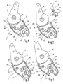
- Fig. 1
- einen Schnitt durch das Ausführungsbeispiel nach dem Verlassen der Nichtgebrauchsstellung,
- Fig. 2
- einen Schnitt entsprechend Fig. 1 beim Übergang in die Gebrauchsstellung vor dem Kontakt zwischen Klinke und zweitem Beschlagteil,
- Fig. 3
- einen Schnitt entsprechend Fig. 2 beim Kontakt zwischen Klinke und zweitem Beschlagteil,
- Fig. 4
- einen Schnitt entsprechend Fig. 3 in der Gebrauchsstellung, und
- Fig. 5
- einen schematisch dargestellten Fahrzeugsitz.
- Fig. 1
- a section through the embodiment after leaving the non-use position,
- Fig. 2
- 1 in the transition to the position of use before the contact between the pawl and the second fitting part,
- Fig. 3
- a section corresponding to FIG. 2 during contact between the pawl and the second fitting part,
- Fig. 4
- a section corresponding to FIG. 3 in the position of use, and
- Fig. 5
- a vehicle seat shown schematically.
Ein als Rastbeschlag ausgebildeter Beschlag 1 weist ein längliches, hohles erstes
Beschlagteil 5, welches in sich einen Bauraum definiert, und ein ebenfalls längliches,
flaches zweites Beschlagteil 8 auf, das teilweise in den Bauraumes eingetaucht
und mittels eines eine Schwenkachse definierenden Gelenkbolzens 10 relativ zum
ersten Beschlagteil 5 schwenkbar gelagert ist. Die nachfolgenden Richtungsangaben
beziehen sich auf das Zylinderkoordinatensystem, welches durch diese
Schwenkachse definiert ist.A designed as a
Eine auf einem zum Gelenkbolzen 10 parallelen ersten Lagerbolzen 13 am ersten
Beschlagteil 5 innerhalb dessen Bauraumes schwenkbar gelagerte Klinke 15 weist
eine einfache erste Verzahnung 17 auf. Am zweiten Beschlagteil 8 ist in dem Bereich,
der in den Bauraum des ersten Beschlagteils 5 eintaucht, eine weitere einfache,
zweite Verzahnung 18 ausgebildet, welche konzentrisch zum Gelenkbolzens 10
gekrümmt ist. Die Klinke 15 wirkt mittels ihrer ersten Verzahnung 17 mit dieser
zweiten Verzahnung 18 des zweiten Beschlagteils 8 zusammen, um den Beschlag 1
in dieser sogenannten Gebrauchsstellung zu verriegeln. Zur Sicherung dieses Eingriffs
im Normalfall ist auf einem zum Gelenkbolzen 10 parallelen zweiten
Lagerbolzen 19 ein Spannexzenter 21 schwenkbar gelagert, welcher im Normalfall
federbelastet an einem Steuernocken 23 der Klinke 15 auf der von der zweiten Verzahnung
18 abgewandten Seite anliegt und die Klinke 15 mit einem schließenden
Moment beaufschlagt. Auf dem zweiten Lagerbolzen 19 ist axial neben dem
Spannexzenter 21 ein Fangstück 25 schwenkbar gelagert, welches im Normalfall in
einem geringen (gegenüber der Zahnhöhe der zweiten Verzahnung 18 und der Klinke
15 kleineren) Abstand zur Klinke 15 auf der von der zweiten Verzahnung 18
abgewandten Seite angeordnet ist und im Crashfall die Klinke 15 abstützt, um ein
Öffnen der Klinke 15 und damit ein ungewolltes Entriegeln des Beschlags 1 zu
verhindern.One on a
Zum Entriegeln des Beschlags 1 wird ein vom Fangstück 25 seitlich abstehender
und durch ein Fenster 27 des Spannexzenters 21 ragender Entriegelungsbolzen 29
bewegt, welcher zunächst das Fangstück 25 schwenkt und nach Überstreichen der
Breite des Fensters 27, also mit einer Zeitverzögerung, den Spannexzenter 21 mitnimmt.
Die Klinke 15 ist dadurch frei und öffnet mit einer beginnenden Bewegung
des zweiten Beschlagteils 8. Beim Zurückschwenken des zweiten Beschlagteils 8 ist
eine Zwangsverriegelung der Klinke 15 mit Erreichen der hintersten Stellung
vorgesehen. Hierzu weist die Klinke 15 an ihrem hinteren Ende, welches beim
ersten Lagerbolzen 13 vorgesehen ist, auf der dem zweiten Beschlagteil 8 zugewandten
Seite eine erste Kontur 31 auf, d.h. eine radial leicht vorspringende, angeformte,
nockenartige Materialpartie. Das zweite Beschlagteil 8 weist im entsprechenden
Bereich, also von der zweiten Verzahnung 18 beabstandet, eine zweite
Kontur 32 auf, die ebenfalls durch eine radial leicht vorspringende, angeformte, nockenartige
Materialpartie gebildet wird.To unlock the
Ausgehend von einem entriegelten und vorgeschwenkten zweiten Beschlagteil 8,
also einer geklappten Nichtgebrauchsstellung des Beschlags 1, wird für einen Übergang
des Beschlags 1 in die Gebrauchsstellung das zweite Beschlagteil 8 zurückgeschwenkt,
wie in Fig. 1 und 2 dargestellt, wobei die Bewegung entgegen dem Uhrzeigersinn
erfolgt. Kurz vor Erreichen der Gebrauchsstellung gelangt die zweite
Kontur 32 des zweiten Beschlagteils 8 in Kontakt mit der ersten Kontur 31 der
Klinke 15, wie in Fig. 3 dargestellt. Das zweite Beschlagteil 8 übt dabei mittels der
zweiten Kontur 32 ein schließendes Moment auf die Klinke 15 an deren erster Kontur
31 aus, wodurch die Klinke 15 auf das zweite Beschlagteil 8 zu schwenkt und in
die zweite Verzahnung 18 einfällt, wie in Fig. 4 dargestellt. Der Beschlag 1 befindet
sich nun in seiner Gebrauchsstellung.Starting from an unlocked and vorwenkten second
Der Beschlag 1 ist im vorliegenden Ausführungsbeispiel bei einem Fahrzeugsitz 41
einer hinteren Sitzreihe eines Kraftfahrzeuges eingesetzt, wo er zur Neigungseinstellung
einer Lehne 42 relativ zu einem Sitzteil 43 des Fahrzeugsitzes 41 dient.
Dabei ist das erste Beschlagteil 5 an der Struktur des Sitzteils 43 angebracht, während
die Lehne 42 am zweiten Beschlagteil 8 befestigt ist. Die erfindungsgemäße
Zwangsverriegelung ist auch bei einem Heckcrash sehr vorteilhaft, wenn die Lehne
42 und damit das zweite Beschlagteil 8 relativ zum ersten Beschlagteil 5 nach hinten
beschleunigt wird, d.h. in der Zeichnung gegen den Uhrzeigersinn. Dabei drückt
die zweite Kontur 32 stärker auf die erste Kontur 31, so daß sich das schließende
Moment auf die Klinke 15 erhöht. Damit steuert die Klinke 15 automatisch nach, so
daß die beiden Verzahnungen 17 und 18 fest in Eingriff miteinander bleiben. The
- 11
- Beschlagfitting
- 55
- erstes Beschlagteilfirst fitting part
- 88th
- zweites Beschlagteilsecond fitting part
- 1010
- Gelenkbolzenhinge pins
- 1313
- erster Lagerbolzenfirst bearing pin
- 1515
- Klinkepawl
- 1717
- erste Verzahnungfirst gearing
- 1818
- zweite Verzahnungsecond gearing
- 1919
- zweiter Lagerbolzensecond bearing pin
- 2121
- Spannexzenterclamping eccentric
- 2323
- Steuernockencontrol cam
- 2525
- Fangstückcatching piece
- 2727
- Fensterwindow
- 2929
- Entriegelungsbolzenunlocking
- 3131
- erste Konturfirst contour
- 3232
- zweite Kontursecond contour
- 4141
- Fahrzeugsitzvehicle seat
- 4242
- Lehnerest
- 4343
- Sitzteilseat part
Claims (10)
Applications Claiming Priority (2)
| Application Number | Priority Date | Filing Date | Title |
|---|---|---|---|
| DE102004011785 | 2004-03-09 | ||
| DE200410011785 DE102004011785B3 (en) | 2004-03-09 | 2004-03-09 | Fitting for vehicle seat has second part exerting closing torque on pawl plate on returning from out-of-use position to use position |
Publications (1)
| Publication Number | Publication Date |
|---|---|
| EP1574388A1 true EP1574388A1 (en) | 2005-09-14 |
Family
ID=34745445
Family Applications (1)
| Application Number | Title | Priority Date | Filing Date |
|---|---|---|---|
| EP05003019A Withdrawn EP1574388A1 (en) | 2004-03-09 | 2005-02-12 | Hinge for a vehicle seat |
Country Status (2)
| Country | Link |
|---|---|
| EP (1) | EP1574388A1 (en) |
| DE (1) | DE102004011785B3 (en) |
Cited By (1)
| Publication number | Priority date | Publication date | Assignee | Title |
|---|---|---|---|---|
| DE102013102536A1 (en) * | 2013-03-13 | 2014-09-18 | Kokinetics Gmbh | Fitting part on a vehicle seat |
Families Citing this family (2)
| Publication number | Priority date | Publication date | Assignee | Title |
|---|---|---|---|---|
| DE102007014370A1 (en) * | 2007-03-26 | 2008-10-02 | Faurecia Autositze Gmbh | vehicle seat |
| DE102011086757B4 (en) * | 2011-11-21 | 2021-06-17 | Adient Luxembourg Holding S.À R.L. | Articulated fitting for an adjusting device of a motor vehicle seat |
Citations (4)
| Publication number | Priority date | Publication date | Assignee | Title |
|---|---|---|---|---|
| DE10240017A1 (en) * | 2001-08-30 | 2003-04-03 | Kochendoerfer & Kiep Metallver | Stop adjuster lock for motor vehicle seat backrest has plate engageable with lock cam and with lock pin to guide it in locking position |
| WO2003033296A1 (en) * | 2001-10-10 | 2003-04-24 | Johnson Controls Gmbh | Vehicle seat with pivoting backrest |
| DE10232030A1 (en) * | 2002-07-16 | 2004-02-05 | Faurecia Autositze Gmbh & Co. Kg | Inclination adjustment fitting for seat back in motor vehicle has protrusions and bearing section of locking pawl distributed around circumference of disc for mounting, with locking pawl and disc located in common functioning plane |
| DE10235141A1 (en) * | 2002-08-01 | 2004-02-12 | Keiper Gmbh & Co. Kg | Locking device for a vehicle seat |
Family Cites Families (5)
| Publication number | Priority date | Publication date | Assignee | Title |
|---|---|---|---|---|
| DE3828223C1 (en) * | 1988-08-19 | 1989-09-28 | Audi Ag, 8070 Ingolstadt, De | Fitting for adjusting the backrest of a motor vehicle |
| DE4235078C2 (en) * | 1992-10-17 | 1996-09-05 | Keiper Recaro Gmbh Co | Adjustment fitting with free pivoting device for the backrest of vehicle seats, in particular motor vehicle seats |
| DE10043890C2 (en) * | 2000-07-14 | 2002-12-05 | Faurecia Autositze Gmbh & Co | Articulated fitting for a vehicle seat with an adjustable backrest |
| DE10048127B4 (en) * | 2000-09-28 | 2008-05-29 | Keiper Gmbh & Co.Kg | Fitting for a vehicle seat |
| DE10224826B4 (en) * | 2002-06-05 | 2007-09-20 | Keiper Gmbh & Co.Kg | Locking device for a vehicle seat |
-
2004
- 2004-03-09 DE DE200410011785 patent/DE102004011785B3/en not_active Expired - Fee Related
-
2005
- 2005-02-12 EP EP05003019A patent/EP1574388A1/en not_active Withdrawn
Patent Citations (4)
| Publication number | Priority date | Publication date | Assignee | Title |
|---|---|---|---|---|
| DE10240017A1 (en) * | 2001-08-30 | 2003-04-03 | Kochendoerfer & Kiep Metallver | Stop adjuster lock for motor vehicle seat backrest has plate engageable with lock cam and with lock pin to guide it in locking position |
| WO2003033296A1 (en) * | 2001-10-10 | 2003-04-24 | Johnson Controls Gmbh | Vehicle seat with pivoting backrest |
| DE10232030A1 (en) * | 2002-07-16 | 2004-02-05 | Faurecia Autositze Gmbh & Co. Kg | Inclination adjustment fitting for seat back in motor vehicle has protrusions and bearing section of locking pawl distributed around circumference of disc for mounting, with locking pawl and disc located in common functioning plane |
| DE10235141A1 (en) * | 2002-08-01 | 2004-02-12 | Keiper Gmbh & Co. Kg | Locking device for a vehicle seat |
Cited By (1)
| Publication number | Priority date | Publication date | Assignee | Title |
|---|---|---|---|---|
| DE102013102536A1 (en) * | 2013-03-13 | 2014-09-18 | Kokinetics Gmbh | Fitting part on a vehicle seat |
Also Published As
| Publication number | Publication date |
|---|---|
| DE102004011785B3 (en) | 2005-08-11 |
Similar Documents
| Publication | Publication Date | Title |
|---|---|---|
| EP1174305B1 (en) | Locking device for a vehicle seat | |
| EP2726324B1 (en) | Fitting system for a vehicle seat | |
| DE102006003243B4 (en) | Fitting for a vehicle seat | |
| DE102012015287A1 (en) | Adjustable vehicle seat | |
| DE102008006980A1 (en) | Vehicle seat assembly | |
| DE102011103225A1 (en) | vehicle seat | |
| DE10241441A1 (en) | Vehicle seat frame and seat with such a frame | |
| DE10052092B4 (en) | Adjustment fitting for a vehicle seat | |
| WO2001000436A1 (en) | Child seat fixing device | |
| EP3694744B1 (en) | Vehicule seat with easy-entry mechanism | |
| DE102006004531B3 (en) | Back rest for vehicle seat, has crash locking device with fixed catch element having longish engagement opening protruding backwards at back part of seat | |
| DE102012012852A1 (en) | Fitting for vehicle seat, particularly for motor-vehicle seat, has fitting portions which are rotated relative to one another and are in geared connection with one another, where third fitting portion is mounted on former fitting portion | |
| EP1574388A1 (en) | Hinge for a vehicle seat | |
| DE102005025002B4 (en) | Fitting for a vehicle seat | |
| DE102005003289A1 (en) | Vehicle seat with ground position | |
| DE10332912B3 (en) | Unlocking device for vehicle seat has unlocking lever with cam lying against locking bolt fixed to safety element | |
| DE102008059355A1 (en) | Fitting system for a vehicle seat | |
| DE102009022979B3 (en) | Length adjuster for seat of two-door motor vehicle, has control device releasing fitting of backrest based on relative movement of memory device, spring provided with two ends, and latch for indirectly locking end of spring | |
| DE202006015871U1 (en) | Arrangement for adjusting backrest of car seat, comprises control ring for release of latch | |
| EP1033279B1 (en) | Hinge for a vehicle seat | |
| DE102013221928B4 (en) | Vehicle seat with an easy entry system | |
| DE102012024643B3 (en) | Vehicle seat, in particular motor vehicle rear seat system | |
| DE10224826B4 (en) | Locking device for a vehicle seat | |
| DE102018222544B4 (en) | Locking arrangement of a component that is movable in relation to a shell, with a convenient adjustment and locking mechanism | |
| DE102004011138B4 (en) | Height and longitudinal adjusting mechanism for vehicle seat, comprising parts engaging in case of impact |
Legal Events
| Date | Code | Title | Description |
|---|---|---|---|
| PUAI | Public reference made under article 153(3) epc to a published international application that has entered the european phase |
Free format text: ORIGINAL CODE: 0009012 |
|
| AK | Designated contracting states |
Kind code of ref document: A1 Designated state(s): AT BE BG CH CY CZ DE DK EE ES FI FR GB GR HU IE IS IT LI LT LU MC NL PL PT RO SE SI SK TR |
|
| AX | Request for extension of the european patent |
Extension state: AL BA HR LV MK YU |
|
| 17P | Request for examination filed |
Effective date: 20051004 |
|
| GRAP | Despatch of communication of intention to grant a patent |
Free format text: ORIGINAL CODE: EPIDOSNIGR1 |
|
| AKX | Designation fees paid |
Designated state(s): DE FR GB PL |
|
| STAA | Information on the status of an ep patent application or granted ep patent |
Free format text: STATUS: THE APPLICATION IS DEEMED TO BE WITHDRAWN |
|
| 18D | Application deemed to be withdrawn |
Effective date: 20060530 |