EP1574367B1 - Achs-Baugruppe für die Verwendung in Anhängern - Google Patents
Achs-Baugruppe für die Verwendung in Anhängern Download PDFInfo
- Publication number
- EP1574367B1 EP1574367B1 EP05076359A EP05076359A EP1574367B1 EP 1574367 B1 EP1574367 B1 EP 1574367B1 EP 05076359 A EP05076359 A EP 05076359A EP 05076359 A EP05076359 A EP 05076359A EP 1574367 B1 EP1574367 B1 EP 1574367B1
- Authority
- EP
- European Patent Office
- Prior art keywords
- axle
- group according
- variable configuration
- trailer
- articulated
- Prior art date
- Legal status (The legal status is an assumption and is not a legal conclusion. Google has not performed a legal analysis and makes no representation as to the accuracy of the status listed.)
- Expired - Lifetime
Links
Images


Classifications
-
- B—PERFORMING OPERATIONS; TRANSPORTING
- B60—VEHICLES IN GENERAL
- B60G—VEHICLE SUSPENSION ARRANGEMENTS
- B60G7/00—Pivoted suspension arms; Accessories thereof
- B60G7/02—Attaching arms to sprung part of vehicle
-
- B—PERFORMING OPERATIONS; TRANSPORTING
- B60—VEHICLES IN GENERAL
- B60G—VEHICLE SUSPENSION ARRANGEMENTS
- B60G17/00—Resilient suspensions having means for adjusting the spring or vibration-damper characteristics, for regulating the distance between a supporting surface and a sprung part of vehicle or for locking suspension during use to meet varying vehicular or surface conditions, e.g. due to speed or load
- B60G17/02—Spring characteristics, e.g. mechanical springs and mechanical adjusting means
- B60G17/04—Spring characteristics, e.g. mechanical springs and mechanical adjusting means fluid spring characteristics
-
- B—PERFORMING OPERATIONS; TRANSPORTING
- B60—VEHICLES IN GENERAL
- B60G—VEHICLE SUSPENSION ARRANGEMENTS
- B60G3/00—Resilient suspensions for a single wheel
- B60G3/02—Resilient suspensions for a single wheel with a single pivoted arm
- B60G3/12—Resilient suspensions for a single wheel with a single pivoted arm the arm being essentially parallel to the longitudinal axis of the vehicle
- B60G3/14—Resilient suspensions for a single wheel with a single pivoted arm the arm being essentially parallel to the longitudinal axis of the vehicle the arm being rigid
-
- B—PERFORMING OPERATIONS; TRANSPORTING
- B62—LAND VEHICLES FOR TRAVELLING OTHERWISE THAN ON RAILS
- B62D—MOTOR VEHICLES; TRAILERS
- B62D13/00—Steering specially adapted for trailers
- B62D13/005—Steering specially adapted for trailers operated from tractor steering system
-
- B—PERFORMING OPERATIONS; TRANSPORTING
- B62—LAND VEHICLES FOR TRAVELLING OTHERWISE THAN ON RAILS
- B62D—MOTOR VEHICLES; TRAILERS
- B62D13/00—Steering specially adapted for trailers
- B62D13/04—Steering specially adapted for trailers for individually-pivoted wheels
-
- B—PERFORMING OPERATIONS; TRANSPORTING
- B60—VEHICLES IN GENERAL
- B60G—VEHICLE SUSPENSION ARRANGEMENTS
- B60G2200/00—Indexing codes relating to suspension types
- B60G2200/10—Independent suspensions
- B60G2200/13—Independent suspensions with longitudinal arms only
- B60G2200/132—Independent suspensions with longitudinal arms only with a single trailing arm
-
- B—PERFORMING OPERATIONS; TRANSPORTING
- B60—VEHICLES IN GENERAL
- B60G—VEHICLE SUSPENSION ARRANGEMENTS
- B60G2200/00—Indexing codes relating to suspension types
- B60G2200/40—Indexing codes relating to the wheels in the suspensions
- B60G2200/44—Indexing codes relating to the wheels in the suspensions steerable
-
- B—PERFORMING OPERATIONS; TRANSPORTING
- B60—VEHICLES IN GENERAL
- B60G—VEHICLE SUSPENSION ARRANGEMENTS
- B60G2202/00—Indexing codes relating to the type of spring, damper or actuator
- B60G2202/10—Type of spring
- B60G2202/15—Fluid spring
-
- B—PERFORMING OPERATIONS; TRANSPORTING
- B60—VEHICLES IN GENERAL
- B60G—VEHICLE SUSPENSION ARRANGEMENTS
- B60G2202/00—Indexing codes relating to the type of spring, damper or actuator
- B60G2202/40—Type of actuator
- B60G2202/41—Fluid actuator
-
- B—PERFORMING OPERATIONS; TRANSPORTING
- B60—VEHICLES IN GENERAL
- B60G—VEHICLE SUSPENSION ARRANGEMENTS
- B60G2206/00—Indexing codes related to the manufacturing of suspensions: constructional features, the materials used, procedures or tools
- B60G2206/01—Constructional features of suspension elements, e.g. arms, dampers, springs
- B60G2206/60—Subframe construction
Definitions
- the present finding refers, in a totally general way, to trailers or trucks a typical use of which is in the field of agriculture and/or forestry.
- axle group of the modular type that is intended to be associated with the quoted trailers, or trucks.
- CH 472 983 shows an axle group for a vehicle that comprises a transversal beam connected to a flat-bed of the vehicle and in a transversal and inferior position with respect to that flat-bed.
- a transversal beam connected to a flat-bed of the vehicle and in a transversal and inferior position with respect to that flat-bed.
- To said transversal beam are articulated, according to a common axis, two identical small frames that are also fitted very close one to the other sideways, said small frames being united to the flat-bed of the vehicle, at an opposite extremity with respect to said articulation, by means of pneumatic elements.
- Each small frame is connected to a respective axle shaft.
- Each pneumatic element is also connected to a portion of beam that extends from the opposite side of the articulation of said axle shafts.
- axle group does not appear to be compact, due in particular to the position of the pneumatic elements.
- FR 2 383 036 shows a suspension for a motor vehicle where an arm of the suspension, connected to the respective axle shaft, can rotate around a first axis parallel to a second axis belonging to a transversal beam, transversally orientated with respect to the direction ot travel of the vehicle.
- the rotation of the suspension is counterbalanced by means of an hydraulic cylinder provided with an elastic element and positioned obliquely with respect to said transversal beam.
- the rotation of the suspension is limited by a stop that abuts against two elastic elements.
- DE 30 08 875 discloses a steering system for a vehicle in which to the axle shafts, an assembly of connecting rods is associated, such assembly comprising a connecting rod that connects the steering elements of the same axle and which is acted upon by double-effect cylinder. Two further stabilizing cylinders are provided for.
- GB 896 181 shows an axle group for a vehicle that comprises a transversal beam connected to a flat-bed of the vehicle and in a transversal and inferior position with respect to that flat-bed.
- a transversal beam connected to a flat-bed of the vehicle and in a transversal and inferior position with respect to that flat-bed.
- two small frames are articulated, according to a common axis, each small frame being connected to the respective axle shaft.
- the small frames also provide, at an opposite end of such articulation on the axle shafts, elements that operate as shock absorbers.
- axle group does not appear to be compact, due in particular to the position of the shock absorbers.
- GB 2 165 195 shows an axle group for a vehicle that has a transversal beam to which two identical small frames are articulated, the small frames being also connected to a respective axle shaft.
- Telescopic shock absorbers connect the axle shaft to the transversal beam and are mounted on plates which raise from the axles, while at the same time the small frames arc fitted on axles, in such a way that shock absorbers do not cross the planes of frames.
- US 3 078 104 shows an axle group for a vehicle that comprise a transversal beam connected to a flat-bed of the vehicle and in a transversal and inferior position with respect to that flat-bed.
- a transversal beam connected to a flat-bed of the vehicle and in a transversal and inferior position with respect to that flat-bed.
- the small frames have, at an opposite end with respect to said articulation relative to the axle shafts, air spring element as shock absorbers.
- Such axle group does not appear to be compact, due in particular to the position of the shock absorbers
- US 4 773 672 discloses a system of hydro pneumatic suspension for a vehicle that comprises a first hydro pneumatic group and a second additional hydro pneumatic group that can be activated by means of a switch.
- WO 00/37301 shows a vehicle chassis that is designed to be retrofitted to a front-wheel motor vehicle.
- the chassis is provided with an axle group arrangement that at its sides comprised two L-shaped plates that are fixed by nuts and bolts.
- the axle group also comprise a rear axle arrangement that connects the two sides of the chassis.
- a variable configuration member for each of the two sideds of the chassis has a lower end articulated to a small frame connected to the respective axle, and has a upper end articulated to the veichle chassis itself.
- the vehicle chassis comprises longitudinal and transversal braces that may also be provided with recesses in low stress regions to reduce the overall weight.
- a purpose of the finding is that of providing an axle group of the modular type that can be used on trailers or trucks having any number of axles, without the requirement to modify the frame, or flat-bed, of said trailers or trucks in any way.
- a further purpose is that of making a modular axle group the structure of which carries all of the elements making up the group, i.e. constitutes a complete and self-supporting assembly, thus capable of withstanding the twisting stresses that occur, so that the flat-bed of the respective truck or trailer, having to withstand substantially just the flexing stresses due to the generally vertical forces, does not have to be strengthened with transversal braces intended to counteract the quoted twisting stresses as happens according to the prior art.
- Another purpose of the finding consists of making an axle group the wheels, or axle shafts, of which are independent.
- Another purpose is that of making an axle group with independent wheels and with hydraulic control that is suitable for keeping the load constant and equally distributed on each wheel of the trailer irrespective of the position in height of said wheels.
- a further purpose is that of providing an axle group with independent wheels and a hydraulic control, and in general braking, which is structured in such a way as to be able to configure said wheels in steering, self-steering or zero steering mode, according to requirements, at the moment of installation on a trailer.
- Another purpose is that of making an axle group of the modular type and with independent wheels with hydraulic control where the wheels can be adjusted in height according to requirements.
- Yet another purpose is that of achieving the quoted objectives in the context of a simple, strong, rational, reliable, functional and compact constructive solution.
- the axle group of the modular type according to the finding comprises a shaped beam intended to be installed transversally and below the flat-bed of a trailer, and two side-by-side identical underlying small frames that are articulated at one end to the quoted beam according to a common transversal horizontal axis so as to be able to oscillate with respect to the beam, whereas at the other end they are joined to the same beam through a respective member with variable configuration, and they each carry a wheel-carrying hub, or axle shaft.
- said small frames extend beyond said transversal common articulation axis in the opposite direction to the direction of travel of the trailer.
- said member with variable configuration consists of an elastically yielding means, the latter typically in the form of an extensible remote-controlled system that can be adjusted according to requirements (automatically or manually) with the trailer both moving and stationary.
- Said extensible system can advantageously consist of a single or double effect hydraulic jack placed under the control of a hydraulic apparatus comprising at least one pneumatic expansion box, or shock-absorber, suitable for also giving the jack the function, indeed, of a shock-absorber.
- said apparatus is structured so as to also equip said jack for the function of a leveller of the trailer, both when moving and when stationary as stated above, with possible exclusion of the quoted pneumatic expansion box.
- FIG. 5 is a perspective view that shows the finding according to a second embodiment, in self-steering version.
- FIG. 6 is the section VI-VI indicated in FIG. 5 .
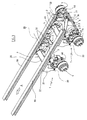
- the aforementioned axle group wholly indicated with reference numeral 1, comprises, in brief, a cross-member 2 that is intended to fix the axle group 1 under the quoted longitudinal members 99, and transversally to them (see FIGS. 3 and 4 ); two identical underlying small flat frames 3 that are carried by the overlying beam 2; and two complete axle shafts 4 that are set on the outer sides of said small frames 3.
- said cross-member 2 comprises, see in particular FIGS. 1 , 5 and 6 , a robust horizontal tubular element with polygonal section 20 the opposite ends of which are fixed to two vertical box-shaped brackets 21.
- the two brackets 21 are shaped forming a right angle, and their dihedral faces downwards and towards the rear zone of the trailer. It should be specified that there is nothing to prevent the brackets 21 from being orientated in the opposite direction, i.e. with the dihedral facing downwards and forwards.
- each bracket 21 carries a platband 22 that is intended to be advantageously fixed under a respective longitudinal member 99, for example with bolts ( FIG. 5 ) or through welding ( FIG. 1 ).
- a platband 22 that is intended to be advantageously fixed under a respective longitudinal member 99, for example with bolts ( FIG. 5 ) or through welding ( FIG. 1 ).
- the quoted holes define a transversal horizontal axis, indicated with 33 in the figures, which constitutes the common front hinging axis of the small frames 3 to the overlying cross-member 2. This takes place through four suitable pins, the two central ones being indicated with 30, and the outer ones being indicated with 31.
- Each individual small frame 3 consists of a flat box-shaped structure 130 lying practically horizontally, which in plan has a form generally shaped like a fork with concavity facing in the direction of travel A.
- the inner arm of said fork-shape is articulated to the respective central pin 30; the outer arm of the same fork-shape is hinged to the respective outer pin 31; and the cross-member of the same fork-shape has, substantially at the centre, a vertical through opening 34 that in plan has the shape of a slot with longitudinal extension perpendicular to the axis 33.
- a fork 35 is fixed that faces the lower mouth of said opening 34, and the arms of which are perforated (see FIG. 2 ), to provide the seat for a transversal horizontal pin 36 ( FIGS. 1 to 4 ).
- the quoted pin 36 has the lower end of a member with variable configuration 37 articulated to it, in the present case consisting of an elastically yielding means 37 that crosses the opening 34 with clearance, beyond which with the opposite upper end it is articulated at 38 ( FIG. 1 ) below the horizontal arm of the respective bracket 21.
- said elastically yielding means consists of a single or double effect hydraulic jack the operative chambers of which are connected to a suitable command and control hydraulic apparatus arranged on board the tractor.
- This apparatus which amongst other things comprises at least one expansion box or pneumatic shock-absorber, shall be better defined hereafter.
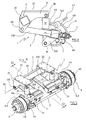
- each small frame 3 has a complete axle shaft 4, i.e. equipped with a respective steering group and with a respective braking group, associated with it.
- axle shafts 4 are generally of the known type, and each of them comprises the following members.
- a bracket generally shaped to form a right-angle 40 that is coplanar with the small frame 3, and the dihedral of which faces forwards and towards the centre of the axle group 1.
- One side of said right-angle shape is received and fixed in a suitable seat 41 formed on the outer side of the rear end of the small frame 3 (see FIG. 2 ), and the remaining side carried a perpendicular through pin, schematised with 44 in FIGS. 1 and 2 .
- the steering arm 42 is articulated to the pin 44.
- the quoted arm 42 carries, see in particular FIG. 2 , on the upper-front side, a support 45 for holding a service pneumatic expansion box 145 for braking; on the outer side the hub-carrying disc 43 with relative winding drum 143 for the attachment of a wheel (rim + tire), not shown for the sake of simplicity and clarity; and at the rear end an eyelet 46.
- Said expansion box 145 per sé normal, is intended, upon the command of the driver of the car that pulls the trailer, to actuate an equally normal lever system 47 with which to activate the braking device (not visible in the figures) arranged between disc 43 and drum 143.
- the eyelets 46 of the steering arms of two aligned axle shafts 4 are joined together by a transversal shaft 5 that is in turn connected, through a central block indicated with 6, to a rod 7 that connects two elastically yielding head devices 77 to the central block 6.
- said rod 7 consists of two identical shock absorbers that are set on either side of the quoted block 6.
- said devices 77 are set behind the small frames 3, and connect them to the inner sides of the steering arms 42 (see Fig. 1 on the right).
- axle group 1 is structured, positioned and sized in such a way as to be able to readily configure the axle group 1 according to the three operating modes indicated hereafter.
- the first mode which we shall call fixed or with zero steering, is the one the foresees installing the axle group 1 on a trailer without the quoted assembly of elements 5, 7 and 77, the disassembly of which comes down to very little given the simple attachment system clearly illustrated in FIG. 1 , and simultaneously disabling the specific function of the pins 44, thanks to a suitable blocking system (not visible in the figures), for example consisting of a simple transversal bolt accessible from the outside.
- Examples of said first mode are given by the front axle group 1 according to FIG. 3 and by the central axle group 1 according to FIG. 4 .
- the second mode which we shall call self-steering, is the one that foresees installing the entire axle group 1 as shown in FIG. 1 ; enabling the pins 44; and providing the elastically yielding devices 77 in the form of double effect hydraulic jacks.
- the operative chambers of the quoted jacks are connected to the hydraulic apparatus (hydraulic distributor) generally arranged on the tractor, and the shock-absorbing effect is given to the component elements of the rod 7, which also operate as anti-wobbling means.
- the quoted devices 77 are slaved to the hydroguide of the steer of the car pulling the trailer, typically through its own command and control hydraulic apparatus, so as to control the steering of the wheels of the axle group 1, limiting it.
- command and control hydraulic apparatus which as stated has at least one expansion box or pneumatic shock-absorber, performs at least the following functions.
- Said levelling action can obviously be enabled both with the trailer moving and stationary, and can advantageously be exploited in various situations.
- it can be used to ease loading and unloading operations of the trailer when stationary, for example by inclining the flat-bed either longitudinally forwards or backwards, or transversally towards one side or the other.
- the quoted apparatus is equipped with means thanks to which the length of the hydraulic cylinders or jacks 37 can be modified as desired at the same time or not as the action of the expansion box or pneumatic shock-absorber.
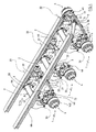
- FIGS. 5 and 6 operates substantially with the same modes explained with reference to the example according to FIGS. 1-4 , and can be associated with a truck or trailer for example as indicated in FIGS. 3 and 4 .
- FIGS. 1-4 The main differences between the first embodiment fully described above ( FIGS. 1-4 ) and the variant according to
- FIGS. 5 and 6 are substantially the following.
- each individual small frame 3 consists of a flat box-shaped structure 230 lying practically horizontally, which in plan has a form generally shaped to form a right-angle, or elbow.
- the two wings of said right-angle shape are respectively arranged parallel and perpendicular to the direction of travel A, and its dihedral faces towards the outside and in the direction of travel A.
- the first of said wings is articulated under the beam 2 through a respective single pin 133, and the second carries the respective complete axle shaft 4, with the elastically yielding device 77 behind.
- Said dihedral receives the jack 37, which at the top is articulated to the respective bracket 21 through the transversal horizontal pin 38, whereas at the bottom it is articulated to the transversal horizontal pin 36 that is carried by two descending ears 330 (see FIG. 6 ) deriving from the transversal wing of the small frame 3.
- the rod 7 forming part of the steering linkage of the axle shafts 4 is split into two distinct shock-absorbers each of which has the outer end directly hinged to the respective steering arm 42, and the inner arm directly hinged under the respective small frame 3.
Landscapes
- Engineering & Computer Science (AREA)
- Mechanical Engineering (AREA)
- Chemical & Material Sciences (AREA)
- Combustion & Propulsion (AREA)
- Transportation (AREA)
- Vehicle Body Suspensions (AREA)
- Investigating Or Analysing Biological Materials (AREA)
- Transition And Organic Metals Composition Catalysts For Addition Polymerization (AREA)
- Stored Programmes (AREA)
- Cephalosporin Compounds (AREA)
Claims (9)
- Achsgruppe für die Zuordnung zu einer gezogenen Vorrichtung wie einem Anhänger mit wenigstens einer Achse, einschließlich eines geformten Querträgers (2), der unter dem Auflieger (99) des Anhängers quer angebracht wird, zwei identischen nebeneinander liegenden kleinen Rahmen (3), von denen jeder eine Achswelle (4) trägt, die an einem Ende zentral an eine gemeinsame Achse (33, 130) des geformten Querträgers gebunden sind, wobei die kleinen Rahmen (3) an dem entfernten Ende der gemeinsamen Achse jeweils durch ein Glied mit variabler Anordnung (37) mit einem oberen und einem unteren Ende an den geformten Querträger gebunden sind, wobei das untere Ende dem kleinen Rahmen zugeordnet ist, dadurch gekennzeichnet, dass das obere Ende des Gliedes mit variabler Anordnung an eine Achse (38) des geformten Querträgers gegliedert ist und das untere Ende des Gliedes mit variabler Anordnung (37) an eine Achse (36) unter dem kleinen Rahmen gegliedert ist.
- Gruppe nach Patentanspruch 1, dadurch gekennzeichnet, dass das Glied mit variabler Anordnung (37) einen hydraulischen Zylinder mit automatischer oder manueller Steuerung beinhaltet, welcher ein pneumatisches Expansionsgehäuse enthält.
- Gruppe nach Patentanspruch 2, dadurch gekennzeichnet, dass die Vorrichtung Mittel beinhaltet, die geeignet sind zum Ändern der Länge des hydraulischen Zylinders, sodass die Ladung konstant und gleichmäßig auf den Rädern verteilt gehalten wird, unabhängig von deren Höhenstellung.
- Gruppe nach Patentanspruch 2, dadurch gekennzeichnet, dass die Vorrichtung Mittel beinhaltet, die geeignet sind zum Ändern der Länge des Hebers, zeitgleich oder nicht zum Betrieb des pneumatischen Expansionsgehäuses.
- Gruppe nach Patentanspruch 1, dadurch gekennzeichnet, dass den Achswellen (4) jeweilige Lenkzapfen und eine Gelenkanordnung zugeordnet sind, die eine Spurstange (5) enthält, welche die Lenkteile einer Achse miteinander verbindet, sowie hydraulische Antriebs- und Steuerheber (7, 77), die jedes der Lenkteile mit dem befestigten Teil der jeweiligen Achswelle verbinden.
- Gruppe nach Patentanspruch 1, dadurch gekennzeichnet, dass jedes Glied mit variabler Anordnung (37) durch eine vertikale Durchlassöffnung (34) läuft, die sich im Wesentlichen im Zentrum jedes kleinen Rahmens (3) befindet.
- Gruppe nach Patentanspruch 1, dadurch gekennzeichnet, dass jedes Glied mit variabler Anordnung (37) in Bezug auf jeden kleinen Rahmen (3) extern durchläuft.
- Gruppe nach Patentanspruch 1, dadurch gekennzeichnet, dass jedes Glied mit variabler Anordnung (37) an einen jeweiligen Sturz (22) gegliedert ist, welcher es im Wesentlichen in einer vertikalen Stellung hält.
- Anhänger oder ähnliches, dadurch gekennzeichnet, dass er mit wenigstens einer Achsgruppe nach einem der Ansprüche 1 bis 8 ausgestattet ist.
Priority Applications (1)
| Application Number | Priority Date | Filing Date | Title |
|---|---|---|---|
| PL05076359T PL1574367T3 (pl) | 2004-07-02 | 2005-06-10 | Grupy osi przygotowane do użycia w przyczepach, w ogólności |
Applications Claiming Priority (2)
| Application Number | Priority Date | Filing Date | Title |
|---|---|---|---|
| IT000078A ITRE20040078A1 (it) | 2004-07-02 | 2004-07-02 | Gruppo assale per l'approntamento di rimorchi in genere |
| ITRE20040078 | 2004-07-02 |
Publications (4)
| Publication Number | Publication Date |
|---|---|
| EP1574367A2 EP1574367A2 (de) | 2005-09-14 |
| EP1574367A9 EP1574367A9 (de) | 2006-03-08 |
| EP1574367A3 EP1574367A3 (de) | 2007-05-02 |
| EP1574367B1 true EP1574367B1 (de) | 2010-02-24 |
Family
ID=34814964
Family Applications (1)
| Application Number | Title | Priority Date | Filing Date |
|---|---|---|---|
| EP05076359A Expired - Lifetime EP1574367B1 (de) | 2004-07-02 | 2005-06-10 | Achs-Baugruppe für die Verwendung in Anhängern |
Country Status (6)
| Country | Link |
|---|---|
| EP (1) | EP1574367B1 (de) |
| AT (1) | ATE458629T1 (de) |
| DE (1) | DE602005019491D1 (de) |
| ES (1) | ES2340774T3 (de) |
| IT (1) | ITRE20040078A1 (de) |
| PL (1) | PL1574367T3 (de) |
Families Citing this family (1)
| Publication number | Priority date | Publication date | Assignee | Title |
|---|---|---|---|---|
| US8820427B2 (en) | 2012-09-06 | 2014-09-02 | Cnh Industrial America Llc | Storage tank frame assembly for an agricultural implement |
Citations (1)
| Publication number | Priority date | Publication date | Assignee | Title |
|---|---|---|---|---|
| WO2000037301A1 (de) * | 1998-12-18 | 2000-06-29 | Al-Ko Kober Ag | Chassis für ein frontgetriebenes kraftfahrzeug |
Family Cites Families (12)
| Publication number | Priority date | Publication date | Assignee | Title |
|---|---|---|---|---|
| NL191871A (de) * | 1953-11-30 | |||
| GB896181A (en) * | 1958-07-29 | 1962-05-09 | Cranes Dereham Ltd | Improvements in road wheel suspensions for road vehicles |
| US3078104A (en) * | 1961-06-07 | 1963-02-19 | Hawker Siddeley Canada Ltd | Independent rear suspension for semi-trailers |
| GB1004481A (en) * | 1962-01-25 | 1965-09-15 | Moulton Development Ltd | Improvements in vehicle wheel suspension systems |
| GB1167648A (en) * | 1967-03-17 | 1969-10-15 | Moulton Development Ltd | Improvements in Vehicle Suspensions |
| DE1630650B2 (de) * | 1967-11-09 | 1976-08-26 | Karl Kässbohrer Fahrzeugwerke GmbH, 7900 Ulm | Kurbelhalbachslagerung fuer lastfahrzeuge |
| FR2063748A5 (de) * | 1969-10-30 | 1971-07-09 | Peugeot & Renault | |
| FR2383036A1 (fr) * | 1977-03-07 | 1978-10-06 | Citroen Sa | Perfectionnements apportes aux suspensions de vehicules |
| DE3008875A1 (de) * | 1980-03-07 | 1981-10-01 | Emil Doll KG, Fahrzeug- u. Karosseriebau, 7603 Oppenau | Daempf- steuerzylinder fuer selbstspurende nachlaufachsen |
| GB2165195B (en) * | 1984-10-05 | 1988-10-05 | Rubery Owen Rockwell Ltd | Running gear for a trailer vehicle |
| FR2600950B1 (fr) * | 1986-07-02 | 1988-10-21 | Peugeot | Suspension hydropneumatique pour vehicule automobile |
| US20030132626A1 (en) * | 2002-01-11 | 2003-07-17 | Carlstedt Robert P. | Incorporation of suspension elements in vehicle frame components |
-
2004
- 2004-07-02 IT IT000078A patent/ITRE20040078A1/it unknown
-
2005
- 2005-06-10 PL PL05076359T patent/PL1574367T3/pl unknown
- 2005-06-10 EP EP05076359A patent/EP1574367B1/de not_active Expired - Lifetime
- 2005-06-10 AT AT05076359T patent/ATE458629T1/de not_active IP Right Cessation
- 2005-06-10 ES ES05076359T patent/ES2340774T3/es not_active Expired - Lifetime
- 2005-06-10 DE DE602005019491T patent/DE602005019491D1/de not_active Expired - Lifetime
Patent Citations (1)
| Publication number | Priority date | Publication date | Assignee | Title |
|---|---|---|---|---|
| WO2000037301A1 (de) * | 1998-12-18 | 2000-06-29 | Al-Ko Kober Ag | Chassis für ein frontgetriebenes kraftfahrzeug |
Also Published As
| Publication number | Publication date |
|---|---|
| EP1574367A2 (de) | 2005-09-14 |
| EP1574367A3 (de) | 2007-05-02 |
| PL1574367T3 (pl) | 2010-07-30 |
| ATE458629T1 (de) | 2010-03-15 |
| ES2340774T3 (es) | 2010-06-09 |
| DE602005019491D1 (de) | 2010-04-08 |
| ITRE20040078A1 (it) | 2004-10-02 |
| EP1574367A9 (de) | 2006-03-08 |
Similar Documents
| Publication | Publication Date | Title |
|---|---|---|
| US6808035B1 (en) | Tandem rear axle suspensions for trucks and truck-tractors | |
| CN101164802B (zh) | 悬架的分组装件 | |
| US2742301A (en) | Deformable cushion suspension for vehicles | |
| CA2952817C (en) | Pneumatic control system for a heavy-duty vehicle | |
| US5330222A (en) | Frame isolator for terminal tractor | |
| US6193266B1 (en) | Vocational air ride tandem axle suspensions | |
| CA2034973A1 (en) | High lift tag axle for trucks | |
| US4279430A (en) | Fifth-wheel suspension system | |
| US5228718A (en) | Air bag and walking beam construction | |
| US4181324A (en) | Overload stabilizer unit for vehicle | |
| AU2012255618B2 (en) | Improvements to haul bodies and related apparatus | |
| EP1574367B1 (de) | Achs-Baugruppe für die Verwendung in Anhängern | |
| US6435526B1 (en) | Axle lifting device for a vehicle | |
| US3827518A (en) | Suspension system for hitch assembly | |
| EP1653392A1 (de) | Auswertung von Höchstwerten unter Benutzung eines Federmodells | |
| AU2008271934A1 (en) | Vehicle suspension system | |
| US3042422A (en) | Dual front wheel assembly with air suspension means | |
| US3936072A (en) | Axle lift mechanism | |
| US7207587B1 (en) | Remote controlled hydraulic gooseneck for tractor trailers | |
| WO1998030404A1 (en) | Tandem rear axle suspensions for trucks and truck-tractors | |
| HU209091B (en) | Air-spring axle | |
| EP0968906B1 (de) | Traktor mit einer Zusatzachse für Traktoranhänger- Kombination | |
| KR100643964B1 (ko) | 후륜 현가장치 구조 | |
| AU2013201290B2 (en) | Improvements to haul bodies | |
| CN119923324A (zh) | 用于多用途车辆底盘的车轴结构,包括车桥 |
Legal Events
| Date | Code | Title | Description |
|---|---|---|---|
| PUAI | Public reference made under article 153(3) epc to a published international application that has entered the european phase |
Free format text: ORIGINAL CODE: 0009012 |
|
| AK | Designated contracting states |
Kind code of ref document: A2 Designated state(s): AT BE BG CH CY CZ DE DK EE ES FI FR GB GR HU IE IS IT LI LT LU MC NL PL PT RO SE SI SK TR |
|
| AX | Request for extension of the european patent |
Extension state: AL BA HR LV MK YU |
|
| PUAL | Search report despatched |
Free format text: ORIGINAL CODE: 0009013 |
|
| AK | Designated contracting states |
Kind code of ref document: A3 Designated state(s): AT BE BG CH CY CZ DE DK EE ES FI FR GB GR HU IE IS IT LI LT LU MC NL PL PT RO SE SI SK TR |
|
| AX | Request for extension of the european patent |
Extension state: AL BA HR LV MK YU |
|
| 17P | Request for examination filed |
Effective date: 20070720 |
|
| AKX | Designation fees paid |
Designated state(s): AT BE BG CH CY CZ DE DK EE ES FI FR GB GR HU IE IS IT LI LT LU MC NL PL PT RO SE SI SK TR |
|
| 17Q | First examination report despatched |
Effective date: 20080530 |
|
| GRAP | Despatch of communication of intention to grant a patent |
Free format text: ORIGINAL CODE: EPIDOSNIGR1 |
|
| GRAS | Grant fee paid |
Free format text: ORIGINAL CODE: EPIDOSNIGR3 |
|
| GRAA | (expected) grant |
Free format text: ORIGINAL CODE: 0009210 |
|
| AK | Designated contracting states |
Kind code of ref document: B1 Designated state(s): AT BE BG CH CY CZ DE DK EE ES FI FR GB GR HU IE IS IT LI LT LU MC NL PL PT RO SE SI SK TR |
|
| REG | Reference to a national code |
Ref country code: GB Ref legal event code: FG4D |
|
| REG | Reference to a national code |
Ref country code: CH Ref legal event code: EP |
|
| REG | Reference to a national code |
Ref country code: IE Ref legal event code: FG4D |
|
| REF | Corresponds to: |
Ref document number: 602005019491 Country of ref document: DE Date of ref document: 20100408 Kind code of ref document: P |
|
| REG | Reference to a national code |
Ref country code: NL Ref legal event code: T3 |
|
| REG | Reference to a national code |
Ref country code: ES Ref legal event code: FG2A Ref document number: 2340774 Country of ref document: ES Kind code of ref document: T3 |
|
| LTIE | Lt: invalidation of european patent or patent extension |
Effective date: 20100224 |
|
| PG25 | Lapsed in a contracting state [announced via postgrant information from national office to epo] |
Ref country code: PT Free format text: LAPSE BECAUSE OF FAILURE TO SUBMIT A TRANSLATION OF THE DESCRIPTION OR TO PAY THE FEE WITHIN THE PRESCRIBED TIME-LIMIT Effective date: 20100625 Ref country code: LT Free format text: LAPSE BECAUSE OF FAILURE TO SUBMIT A TRANSLATION OF THE DESCRIPTION OR TO PAY THE FEE WITHIN THE PRESCRIBED TIME-LIMIT Effective date: 20100224 Ref country code: IS Free format text: LAPSE BECAUSE OF FAILURE TO SUBMIT A TRANSLATION OF THE DESCRIPTION OR TO PAY THE FEE WITHIN THE PRESCRIBED TIME-LIMIT Effective date: 20100624 |
|
| REG | Reference to a national code |
Ref country code: PL Ref legal event code: T3 |
|
| PG25 | Lapsed in a contracting state [announced via postgrant information from national office to epo] |
Ref country code: AT Free format text: LAPSE BECAUSE OF FAILURE TO SUBMIT A TRANSLATION OF THE DESCRIPTION OR TO PAY THE FEE WITHIN THE PRESCRIBED TIME-LIMIT Effective date: 20100224 Ref country code: FI Free format text: LAPSE BECAUSE OF FAILURE TO SUBMIT A TRANSLATION OF THE DESCRIPTION OR TO PAY THE FEE WITHIN THE PRESCRIBED TIME-LIMIT Effective date: 20100224 Ref country code: SI Free format text: LAPSE BECAUSE OF FAILURE TO SUBMIT A TRANSLATION OF THE DESCRIPTION OR TO PAY THE FEE WITHIN THE PRESCRIBED TIME-LIMIT Effective date: 20100224 |
|
| PG25 | Lapsed in a contracting state [announced via postgrant information from national office to epo] |
Ref country code: SE Free format text: LAPSE BECAUSE OF FAILURE TO SUBMIT A TRANSLATION OF THE DESCRIPTION OR TO PAY THE FEE WITHIN THE PRESCRIBED TIME-LIMIT Effective date: 20100224 Ref country code: GR Free format text: LAPSE BECAUSE OF FAILURE TO SUBMIT A TRANSLATION OF THE DESCRIPTION OR TO PAY THE FEE WITHIN THE PRESCRIBED TIME-LIMIT Effective date: 20100525 Ref country code: EE Free format text: LAPSE BECAUSE OF FAILURE TO SUBMIT A TRANSLATION OF THE DESCRIPTION OR TO PAY THE FEE WITHIN THE PRESCRIBED TIME-LIMIT Effective date: 20100224 Ref country code: RO Free format text: LAPSE BECAUSE OF FAILURE TO SUBMIT A TRANSLATION OF THE DESCRIPTION OR TO PAY THE FEE WITHIN THE PRESCRIBED TIME-LIMIT Effective date: 20100224 Ref country code: CY Free format text: LAPSE BECAUSE OF FAILURE TO SUBMIT A TRANSLATION OF THE DESCRIPTION OR TO PAY THE FEE WITHIN THE PRESCRIBED TIME-LIMIT Effective date: 20100224 Ref country code: BE Free format text: LAPSE BECAUSE OF FAILURE TO SUBMIT A TRANSLATION OF THE DESCRIPTION OR TO PAY THE FEE WITHIN THE PRESCRIBED TIME-LIMIT Effective date: 20100224 |
|
| PG25 | Lapsed in a contracting state [announced via postgrant information from national office to epo] |
Ref country code: SK Free format text: LAPSE BECAUSE OF FAILURE TO SUBMIT A TRANSLATION OF THE DESCRIPTION OR TO PAY THE FEE WITHIN THE PRESCRIBED TIME-LIMIT Effective date: 20100224 Ref country code: CZ Free format text: LAPSE BECAUSE OF FAILURE TO SUBMIT A TRANSLATION OF THE DESCRIPTION OR TO PAY THE FEE WITHIN THE PRESCRIBED TIME-LIMIT Effective date: 20100224 Ref country code: BG Free format text: LAPSE BECAUSE OF FAILURE TO SUBMIT A TRANSLATION OF THE DESCRIPTION OR TO PAY THE FEE WITHIN THE PRESCRIBED TIME-LIMIT Effective date: 20100524 |
|
| PLBE | No opposition filed within time limit |
Free format text: ORIGINAL CODE: 0009261 |
|
| STAA | Information on the status of an ep patent application or granted ep patent |
Free format text: STATUS: NO OPPOSITION FILED WITHIN TIME LIMIT |
|
| PG25 | Lapsed in a contracting state [announced via postgrant information from national office to epo] |
Ref country code: MC Free format text: LAPSE BECAUSE OF NON-PAYMENT OF DUE FEES Effective date: 20100630 Ref country code: DK Free format text: LAPSE BECAUSE OF FAILURE TO SUBMIT A TRANSLATION OF THE DESCRIPTION OR TO PAY THE FEE WITHIN THE PRESCRIBED TIME-LIMIT Effective date: 20100224 |
|
| REG | Reference to a national code |
Ref country code: CH Ref legal event code: PL |
|
| 26N | No opposition filed |
Effective date: 20101125 |
|
| PG25 | Lapsed in a contracting state [announced via postgrant information from national office to epo] |
Ref country code: LI Free format text: LAPSE BECAUSE OF NON-PAYMENT OF DUE FEES Effective date: 20100630 Ref country code: CH Free format text: LAPSE BECAUSE OF NON-PAYMENT OF DUE FEES Effective date: 20100630 Ref country code: IE Free format text: LAPSE BECAUSE OF NON-PAYMENT OF DUE FEES Effective date: 20100610 |
|
| PG25 | Lapsed in a contracting state [announced via postgrant information from national office to epo] |
Ref country code: HU Free format text: LAPSE BECAUSE OF FAILURE TO SUBMIT A TRANSLATION OF THE DESCRIPTION OR TO PAY THE FEE WITHIN THE PRESCRIBED TIME-LIMIT Effective date: 20100825 Ref country code: LU Free format text: LAPSE BECAUSE OF NON-PAYMENT OF DUE FEES Effective date: 20100610 |
|
| PG25 | Lapsed in a contracting state [announced via postgrant information from national office to epo] |
Ref country code: TR Free format text: LAPSE BECAUSE OF FAILURE TO SUBMIT A TRANSLATION OF THE DESCRIPTION OR TO PAY THE FEE WITHIN THE PRESCRIBED TIME-LIMIT Effective date: 20100224 |
|
| REG | Reference to a national code |
Ref country code: FR Ref legal event code: PLFP Year of fee payment: 12 |
|
| REG | Reference to a national code |
Ref country code: FR Ref legal event code: PLFP Year of fee payment: 13 |
|
| REG | Reference to a national code |
Ref country code: FR Ref legal event code: PLFP Year of fee payment: 14 |
|
| PGFP | Annual fee paid to national office [announced via postgrant information from national office to epo] |
Ref country code: NL Payment date: 20220626 Year of fee payment: 18 Ref country code: IT Payment date: 20220328 Year of fee payment: 18 Ref country code: GB Payment date: 20220628 Year of fee payment: 18 |
|
| PGFP | Annual fee paid to national office [announced via postgrant information from national office to epo] |
Ref country code: PL Payment date: 20220520 Year of fee payment: 18 |
|
| PGFP | Annual fee paid to national office [announced via postgrant information from national office to epo] |
Ref country code: FR Payment date: 20220627 Year of fee payment: 18 |
|
| PGFP | Annual fee paid to national office [announced via postgrant information from national office to epo] |
Ref country code: ES Payment date: 20220701 Year of fee payment: 18 Ref country code: DE Payment date: 20220629 Year of fee payment: 18 |
|
| REG | Reference to a national code |
Ref country code: DE Ref legal event code: R119 Ref document number: 602005019491 Country of ref document: DE |
|
| REG | Reference to a national code |
Ref country code: NL Ref legal event code: MM Effective date: 20230701 |
|
| GBPC | Gb: european patent ceased through non-payment of renewal fee |
Effective date: 20230610 |
|
| PG25 | Lapsed in a contracting state [announced via postgrant information from national office to epo] |
Ref country code: NL Free format text: LAPSE BECAUSE OF NON-PAYMENT OF DUE FEES Effective date: 20230701 |
|
| PG25 | Lapsed in a contracting state [announced via postgrant information from national office to epo] |
Ref country code: DE Free format text: LAPSE BECAUSE OF NON-PAYMENT OF DUE FEES Effective date: 20240103 Ref country code: GB Free format text: LAPSE BECAUSE OF NON-PAYMENT OF DUE FEES Effective date: 20230610 |
|
| PG25 | Lapsed in a contracting state [announced via postgrant information from national office to epo] |
Ref country code: FR Free format text: LAPSE BECAUSE OF NON-PAYMENT OF DUE FEES Effective date: 20230630 |
|
| REG | Reference to a national code |
Ref country code: ES Ref legal event code: FD2A Effective date: 20240729 |
|
| PG25 | Lapsed in a contracting state [announced via postgrant information from national office to epo] |
Ref country code: IT Free format text: LAPSE BECAUSE OF NON-PAYMENT OF DUE FEES Effective date: 20230610 |
|
| PG25 | Lapsed in a contracting state [announced via postgrant information from national office to epo] |
Ref country code: ES Free format text: LAPSE BECAUSE OF NON-PAYMENT OF DUE FEES Effective date: 20230611 |
|
| PG25 | Lapsed in a contracting state [announced via postgrant information from national office to epo] |
Ref country code: PL Free format text: LAPSE BECAUSE OF NON-PAYMENT OF DUE FEES Effective date: 20230610 |
|
| PG25 | Lapsed in a contracting state [announced via postgrant information from national office to epo] |
Ref country code: PL Free format text: LAPSE BECAUSE OF NON-PAYMENT OF DUE FEES Effective date: 20230610 Ref country code: ES Free format text: LAPSE BECAUSE OF NON-PAYMENT OF DUE FEES Effective date: 20230611 |