EP1574267B1 - Biegemaschine - Google Patents
Biegemaschine Download PDFInfo
- Publication number
- EP1574267B1 EP1574267B1 EP05005388A EP05005388A EP1574267B1 EP 1574267 B1 EP1574267 B1 EP 1574267B1 EP 05005388 A EP05005388 A EP 05005388A EP 05005388 A EP05005388 A EP 05005388A EP 1574267 B1 EP1574267 B1 EP 1574267B1
- Authority
- EP
- European Patent Office
- Prior art keywords
- bending
- bending machine
- bent
- machine according
- parallelograms
- Prior art date
- Legal status (The legal status is an assumption and is not a legal conclusion. Google has not performed a legal analysis and makes no representation as to the accuracy of the status listed.)
- Expired - Lifetime
Links
- 238000005452 bending Methods 0.000 title claims abstract description 30
- 230000001360 synchronised effect Effects 0.000 claims abstract description 6
- PCTMTFRHKVHKIS-BMFZQQSSSA-N (1s,3r,4e,6e,8e,10e,12e,14e,16e,18s,19r,20r,21s,25r,27r,30r,31r,33s,35r,37s,38r)-3-[(2r,3s,4s,5s,6r)-4-amino-3,5-dihydroxy-6-methyloxan-2-yl]oxy-19,25,27,30,31,33,35,37-octahydroxy-18,20,21-trimethyl-23-oxo-22,39-dioxabicyclo[33.3.1]nonatriaconta-4,6,8,10 Chemical compound C1C=C2C[C@@H](OS(O)(=O)=O)CC[C@]2(C)[C@@H]2[C@@H]1[C@@H]1CC[C@H]([C@H](C)CCCC(C)C)[C@@]1(C)CC2.O[C@H]1[C@@H](N)[C@H](O)[C@@H](C)O[C@H]1O[C@H]1/C=C/C=C/C=C/C=C/C=C/C=C/C=C/[C@H](C)[C@@H](O)[C@@H](C)[C@H](C)OC(=O)C[C@H](O)C[C@H](O)CC[C@@H](O)[C@H](O)C[C@H](O)C[C@](O)(C[C@H](O)[C@H]2C(O)=O)O[C@H]2C1 PCTMTFRHKVHKIS-BMFZQQSSSA-N 0.000 claims 2
- 239000002184 metal Substances 0.000 abstract 1
- 238000006073 displacement reaction Methods 0.000 description 2
- 238000000034 method Methods 0.000 description 1
Images
Classifications
-
- B—PERFORMING OPERATIONS; TRANSPORTING
- B21—MECHANICAL METAL-WORKING WITHOUT ESSENTIALLY REMOVING MATERIAL; PUNCHING METAL
- B21D—WORKING OR PROCESSING OF SHEET METAL OR METAL TUBES, RODS OR PROFILES WITHOUT ESSENTIALLY REMOVING MATERIAL; PUNCHING METAL
- B21D7/00—Bending rods, profiles, or tubes
- B21D7/02—Bending rods, profiles, or tubes over a stationary forming member; by use of a swinging forming member or abutment
- B21D7/024—Bending rods, profiles, or tubes over a stationary forming member; by use of a swinging forming member or abutment by a swinging forming member
- B21D7/025—Bending rods, profiles, or tubes over a stationary forming member; by use of a swinging forming member or abutment by a swinging forming member and pulling or pushing the ends of the work
-
- B—PERFORMING OPERATIONS; TRANSPORTING
- B21—MECHANICAL METAL-WORKING WITHOUT ESSENTIALLY REMOVING MATERIAL; PUNCHING METAL
- B21D—WORKING OR PROCESSING OF SHEET METAL OR METAL TUBES, RODS OR PROFILES WITHOUT ESSENTIALLY REMOVING MATERIAL; PUNCHING METAL
- B21D11/00—Bending not restricted to forms of material mentioned in only one of groups B21D5/00, B21D7/00, B21D9/00; Bending not provided for in groups B21D5/00 - B21D9/00; Twisting
- B21D11/20—Bending sheet metal, not otherwise provided for
Definitions
- the invention relates to a bending machine for bending tabs, sheets, profiles, round material and thick-walled pipe according to the preamble of claim 1.
- a bending machine with two clamps which is constructed mirror-symmetrically to its central axis and has lifting elements, which are arranged in the form of two parallelograms.
- the parallelograms change their internal angles during the bending process, being synchronized with a pair of operatively engaged tooth segments.
- a disadvantage of this arrangement is that the bending machine can not be used from the outset for a variety of materials and angles, but must first be laboriously rebuilt. This requires time and increased personnel costs, so that the machine is impractical just in various different applications, such as those found in workshops.
- the object of the invention is therefore to provide a bending machine, which can be quickly and easily meet a wide variety of applications. This will solved by the special features of the characterizing part of claim 1, which have the following special significance.
- the bending machine has a second pair of interacting with each other toothed segments, which is arranged on the two actuating levers and serves to synchronize them. This makes it possible to align the terminals depending on the application to each other and still perform the processing of the workpiece using the operating lever.
- the bending machine exerts a pure bending moment on the material in order to be able to bend it in an arbitrary radius.
- the parallelogram A, B, C, D has a fixed pivot F.
- the parallelogram A ', B', C ', D' has a fixed pivot point F '.
- the synchronization mechanism between the two arms A and A ' consists of the tooth segments, which are a part of arm A and A', respectively.
- the two toothed segments engage each other.
- the terminals H and H ' can move freely to the right and left, but are synchronized symmetrically to each other.
- the entire machine is symmetrical with respect to axis S.
- the clamps H and H ' are fixedly mounted on the arms D and D' respectively.
Landscapes
- Engineering & Computer Science (AREA)
- Mechanical Engineering (AREA)
- Bending Of Plates, Rods, And Pipes (AREA)
- Shaping Of Tube Ends By Bending Or Straightening (AREA)
Description
- Die Erfindung betrifft eine Biegemaschine für das Biegen von Laschen, Blechen, Profilen, rundem Material und dickwandigem Rohr gemäß dem Oberbegriff des Anspruches 1.
- Aus der
US 4,798,073 ist eine Biegemaschine mit zwei Klemmen bekannt, welche spiegelsymmetrisch zu ihrer Mittelachse aufgebaut ist und Hebeelemente aufweist, welche in Form von zwei Parallelogrammen angeordnet sind. Die Parallelogramme verändern während des Biegevorgangs ihre Innenwinkel, wobei sie mit einem Paar von in Wirkverbindung stehenden Zahnsegmenten synchronisiert werden. Nachteilig bei dieser Anordnung ist, dass die Biegemaschine nicht von vornherein für verschiedenste Materialien und Winkel verwendet werden kann, sondern zunächst umständlich umgebaut werden muss. Dies erfordert Zeit und einen erhöhten Personalaufwand, so dass die Maschine gerade bei verschiedenen unterschiedlichen Anwendungsfällen, wie sie beispielsweise in Werkstätten vorkommen, unpraktisch ist. - Aufgabe der Erfindung ist es daher, eine Biegemaschine zu schaffen, welche schnell und einfach unterschiedlichsten Anwendungsfällen gerecht werden kann. Dies wird durch die besonderen Merkmale des kennzeichnenden Teils von Anspruch 1 gelöst, denen folgende besondere Bedeutung zukommt.
- Die Biegemaschine verfügt über ein zweites Paar von miteinander in Wirkverbindung stehenden Zahnsegmenten, welches an den beiden Betätigungshebeln angeordnet ist und zu deren Synchronisierung dient. Hierdurch ist es möglich, die Klemmen je nach Anwendungsfall zueinander auszurichten und trotzdem mit Hilfe der Betätigungshebel die Bearbeitung des Werkstückes durchzuführen. Hierbei übt die Biegemaschine ein reines Biegemoment auf das Material aus, um dieses in einem willkürlichen Radius biegen zu können.
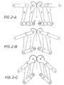
- Auf dieser Seite sehen wir das Prinzip der Biegemaschine in drei Positionen.
- In Abbildung 2-A sehen wir, dass die Maschine aus zwei symmetrischen Parallelogrammen besteht.
- Das Parallelogramm A, B, C, D hat einen festen Drehpunkt F.
- Das Parallelogramm A', B', C', D' hat einen festen Drehpunkt F'.
- Der Synchronisierungsmechanismus zwischen den zwei Armen A und A' besteht aus den Zahnsegmenten, die ein Bestandteil von Arm A bzw. A' sind.
- Die beiden Zahnsegmente greifen ineinander ein.
- Die Klemmen H und H' können sich frei nach rechts und links bewegen, sind jedoch zueinander symmetrisch synchronisiert.
- Die gesamte Maschine ist in Bezug auf Achse S symmetrisch.
- Alle Drehpunkte sind so gelagert, dass eine minimale Reibung entsteht.
- Die Klemmen H und H' sind fest auf den Armen D bzw. D' montiert.
- Die auf Arm C und C' ausgeübte Winkelverschiebung verursacht über die Arme A und B bzw. A' und B' eine gleiche Winkelverschiebung auf den Klemmen H und H', was in Abbildung 2-B zu sehen ist.
- Falls die Arme C und C' bewegt werden, ist das Ergebnis, dass ein reines Biegemoment auf das zwischen den Klemmen H und H' eingespannte Produkt ausgeübt wird (siehe auch Abbildung 1-C).
- Durch Ausübung dieses reinen Biegemoments wird das Produkt einen sauberen Radius annehmen.
- In Abbildung 2-C ist zu sehen, dass ein integriertes Zahnsegment an den Hebeln C und C' dafür sorgt, dass die Bewegungen dieser Hebel synchronisiert sind.
- Dieses Zahnsegment wurde in Abbildung 2-A weggelassen, da sonst die Zahnsegmente von Hebel A und A' nicht sichtbar wären.
Claims (5)
- Biegemaschine zum Biegen von Laschen, Blechen, Profilen, rundem Material und dickwandigem Rohr,
wobei die Biegemaschine spiegelsymmetrisch zu ihrer Mittelachse (S) aufgebaut ist,
mit Klemmen (H, H'), in denen das zu biegende Werkstück während des Biegevorgangs gehaltert wird,
mit Hebelelementen, welche in Form von zwei Parallelogrammen (ABCD, A'B'C'D') angeordnet sind, die während des Biegevorgangs ihre Innenwinkel ändern, wobei jedes der Parallelogramme ein Hebelelement (C, C') aufweist, welches als Betätigungshebel fungiert,
mit einem Paar von in Wirkverbindung stehenden Zahnsegmenten, durch welches die Parallelogramme (ABCD, A'B'C'D') so synchronisiert werden, dass die Biegemaschine während des gesamten Biegevorgangs spiegelsymmetrisch zur Mittelachse (S) bleibt,
wobei bei Betätigung mittels der Betätigungshebel durch die Biegemaschine ein reines Biegemoment auf das zu biegende Werkstück ausübbar ist,
dadurch gekennzeichnet,
dass noch ein zweites Paar von miteinander in Wirkverbindung stehenden Zahnsegmenten vorgesehen ist, welches an den beiden Betätigungshebeln (C, C') angeordnet ist und zu deren Synchronisierung dient. - Biegemaschine nach Anspruch 1, dadurch gekennzeichnet, dass die Klemmen (H, H') frei seitlich verschiebbar, jedoch miteinander synchronisiert sind.
- Biegemaschine nach einem der Ansprüche 1. oder 2, dadurch gekennzeichnet, dass Profile gebogen werden können, die symmetrisch zur Biegefläche sind.
- Biegemaschine nach Anspruch 3, dadurch gekennzeichnet, dass ein großer Winkel von bis zu 200° herstellbar ist.
- Biegemaschine nach einem der Ansprüche 1 bis 4, dadurch gekennzeichnet, dass alle Drehpunkte so gelagert sind, dass minimale Reibung entsteht.
Applications Claiming Priority (2)
| Application Number | Priority Date | Filing Date | Title |
|---|---|---|---|
| NL1025692A NL1025692C1 (nl) | 2004-03-11 | 2004-03-11 | Buigmachine voor het buigen van strippen, platen, profielen, rond materiaal en dikwandige buis. |
| NL1025692 | 2004-03-11 |
Publications (2)
| Publication Number | Publication Date |
|---|---|
| EP1574267A1 EP1574267A1 (de) | 2005-09-14 |
| EP1574267B1 true EP1574267B1 (de) | 2007-12-26 |
Family
ID=34825253
Family Applications (1)
| Application Number | Title | Priority Date | Filing Date |
|---|---|---|---|
| EP05005388A Expired - Lifetime EP1574267B1 (de) | 2004-03-11 | 2005-03-11 | Biegemaschine |
Country Status (4)
| Country | Link |
|---|---|
| EP (1) | EP1574267B1 (de) |
| AT (1) | ATE381971T1 (de) |
| DE (1) | DE502005002325D1 (de) |
| NL (1) | NL1025692C1 (de) |
Families Citing this family (1)
| Publication number | Priority date | Publication date | Assignee | Title |
|---|---|---|---|---|
| CN108453159A (zh) * | 2018-04-11 | 2018-08-28 | 盐城中自科技有限公司 | 一种换热器折弯机构及折弯方法 |
Family Cites Families (3)
| Publication number | Priority date | Publication date | Assignee | Title |
|---|---|---|---|---|
| US3952572A (en) * | 1974-01-23 | 1976-04-27 | Case Western Reserve University | Beam bender |
| DE3544056A1 (de) * | 1985-12-13 | 1987-06-25 | Helmut Dischler | Biegemaschine |
| JPH0818072B2 (ja) * | 1994-02-23 | 1996-02-28 | 泰太郎 山本 | 板金加工機 |
-
2004
- 2004-03-11 NL NL1025692A patent/NL1025692C1/nl not_active IP Right Cessation
-
2005
- 2005-03-11 AT AT05005388T patent/ATE381971T1/de not_active IP Right Cessation
- 2005-03-11 EP EP05005388A patent/EP1574267B1/de not_active Expired - Lifetime
- 2005-03-11 DE DE502005002325T patent/DE502005002325D1/de not_active Expired - Fee Related
Also Published As
| Publication number | Publication date |
|---|---|
| DE502005002325D1 (de) | 2008-02-07 |
| NL1025692C1 (nl) | 2005-09-13 |
| EP1574267A1 (de) | 2005-09-14 |
| ATE381971T1 (de) | 2008-01-15 |
Similar Documents
| Publication | Publication Date | Title |
|---|---|---|
| EP0022122B1 (de) | Biegemaschine | |
| DE3327509C2 (de) | Rohrbiegemaschine | |
| DE2514187C2 (de) | Vorrichtung zum Herstellen von Bügeln | |
| EP2289643B1 (de) | Vorrichtung zum Biegen länglicher Werkstücke | |
| DE2237895C3 (de) | Einrichtung zum Abwinkein von Baustahlmatten | |
| DE2112743C3 (de) | Reckschmiedevorrichtung zum Recken eines langen, knüppeiförmigen Vorwerkstückes mit einem Manipulator auf nur einer Seite einer Schmiedepresse | |
| EP0513864A2 (de) | Verfahren zum Betrieb einer Rohrbiegemaschine | |
| DE2537382C2 (de) | ||
| AT396076B (de) | Biegemaschine fuer blattfedern | |
| EP1574267B1 (de) | Biegemaschine | |
| DE2913816C2 (de) | ||
| DE4412590C2 (de) | Vorrichtung zum Bördeln von Blechen | |
| EP0585613B1 (de) | Blechwalzmaschine | |
| DE602005003524T2 (de) | Biegevorrichtung | |
| DE2612304B2 (de) | Biegemaschine für stabförmiges Material, insbesondere für Betonbewehrungsstäbe | |
| DE2304838A1 (de) | Rohrbiegevorrichtung an einer rohrstauchbiegemaschine | |
| DE19853294A1 (de) | Vorrichtung zum Streckbiegen von Metallstäben oder -profilen | |
| DE263144C (de) | ||
| DE3104274C2 (de) | Zwischenbauteil zur Steigerung der Preßkraft | |
| EP1324841B1 (de) | Vorrichtung zum biegen einer materialbahn | |
| DE1179534B (de) | Einrichtung an Werkzeug-, insbesondere Maschinen zum Biegen von Draht und Rohren, zum Verschieben des Werkzeugs, insbesondere einer Biegerolle, nach einer vorgegebenen, nicht-linearen Gesetzmaessigkeit | |
| DE202013104199U1 (de) | Vorrichtung zum Biegen von Rohren | |
| DE2419231B2 (de) | Vorrichtung zum schrittweisen Gittertransport um unterschiedliche Beträge bei einer Gitterschweißmaschine | |
| DE19630163C1 (de) | Biegevorrichtung | |
| DE1237408B (de) | Vorrichtung zum Biegen von Rohren, Staeben, Profilen od. dgl. |
Legal Events
| Date | Code | Title | Description |
|---|---|---|---|
| PUAI | Public reference made under article 153(3) epc to a published international application that has entered the european phase |
Free format text: ORIGINAL CODE: 0009012 |
|
| AK | Designated contracting states |
Kind code of ref document: A1 Designated state(s): AT BE BG CH CY CZ DE DK EE ES FI FR GB GR HU IE IS IT LI LT LU MC NL PL PT RO SE SI SK TR |
|
| AX | Request for extension of the european patent |
Extension state: AL BA HR LV MK YU |
|
| 17P | Request for examination filed |
Effective date: 20060222 |
|
| AKX | Designation fees paid |
Designated state(s): AT BE BG CH CY CZ DE DK EE ES FI FR GB GR HU IE IS IT LI LT LU MC NL PL PT RO SE SI SK TR |
|
| 17Q | First examination report despatched |
Effective date: 20070111 |
|
| GRAP | Despatch of communication of intention to grant a patent |
Free format text: ORIGINAL CODE: EPIDOSNIGR1 |
|
| GRAS | Grant fee paid |
Free format text: ORIGINAL CODE: EPIDOSNIGR3 |
|
| GRAA | (expected) grant |
Free format text: ORIGINAL CODE: 0009210 |
|
| AK | Designated contracting states |
Kind code of ref document: B1 Designated state(s): AT BE BG CH CY CZ DE DK EE ES FI FR GB GR HU IE IS IT LI LT LU MC NL PL PT RO SE SI SK TR |
|
| REG | Reference to a national code |
Ref country code: GB Ref legal event code: FG4D Free format text: NOT ENGLISH |
|
| REG | Reference to a national code |
Ref country code: IE Ref legal event code: FG4D Free format text: LANGUAGE OF EP DOCUMENT: GERMAN |
|
| REG | Reference to a national code |
Ref country code: CH Ref legal event code: EP |
|
| REF | Corresponds to: |
Ref document number: 502005002325 Country of ref document: DE Date of ref document: 20080207 Kind code of ref document: P |
|
| PG25 | Lapsed in a contracting state [announced via postgrant information from national office to epo] |
Ref country code: SE Free format text: LAPSE BECAUSE OF FAILURE TO SUBMIT A TRANSLATION OF THE DESCRIPTION OR TO PAY THE FEE WITHIN THE PRESCRIBED TIME-LIMIT Effective date: 20080326 |
|
| PG25 | Lapsed in a contracting state [announced via postgrant information from national office to epo] |
Ref country code: SI Free format text: LAPSE BECAUSE OF FAILURE TO SUBMIT A TRANSLATION OF THE DESCRIPTION OR TO PAY THE FEE WITHIN THE PRESCRIBED TIME-LIMIT Effective date: 20071226 Ref country code: NL Free format text: LAPSE BECAUSE OF FAILURE TO SUBMIT A TRANSLATION OF THE DESCRIPTION OR TO PAY THE FEE WITHIN THE PRESCRIBED TIME-LIMIT Effective date: 20071226 Ref country code: PL Free format text: LAPSE BECAUSE OF FAILURE TO SUBMIT A TRANSLATION OF THE DESCRIPTION OR TO PAY THE FEE WITHIN THE PRESCRIBED TIME-LIMIT Effective date: 20071226 Ref country code: FI Free format text: LAPSE BECAUSE OF FAILURE TO SUBMIT A TRANSLATION OF THE DESCRIPTION OR TO PAY THE FEE WITHIN THE PRESCRIBED TIME-LIMIT Effective date: 20071226 |
|
| NLV1 | Nl: lapsed or annulled due to failure to fulfill the requirements of art. 29p and 29m of the patents act | ||
| GBV | Gb: ep patent (uk) treated as always having been void in accordance with gb section 77(7)/1977 [no translation filed] | ||
| PG25 | Lapsed in a contracting state [announced via postgrant information from national office to epo] |
Ref country code: IS Free format text: LAPSE BECAUSE OF FAILURE TO SUBMIT A TRANSLATION OF THE DESCRIPTION OR TO PAY THE FEE WITHIN THE PRESCRIBED TIME-LIMIT Effective date: 20080426 Ref country code: CZ Free format text: LAPSE BECAUSE OF FAILURE TO SUBMIT A TRANSLATION OF THE DESCRIPTION OR TO PAY THE FEE WITHIN THE PRESCRIBED TIME-LIMIT Effective date: 20071226 Ref country code: ES Free format text: LAPSE BECAUSE OF FAILURE TO SUBMIT A TRANSLATION OF THE DESCRIPTION OR TO PAY THE FEE WITHIN THE PRESCRIBED TIME-LIMIT Effective date: 20080406 Ref country code: LT Free format text: LAPSE BECAUSE OF FAILURE TO SUBMIT A TRANSLATION OF THE DESCRIPTION OR TO PAY THE FEE WITHIN THE PRESCRIBED TIME-LIMIT Effective date: 20071226 |
|
| PGFP | Annual fee paid to national office [announced via postgrant information from national office to epo] |
Ref country code: DE Payment date: 20080304 Year of fee payment: 4 |
|
| PG25 | Lapsed in a contracting state [announced via postgrant information from national office to epo] |
Ref country code: SK Free format text: LAPSE BECAUSE OF FAILURE TO SUBMIT A TRANSLATION OF THE DESCRIPTION OR TO PAY THE FEE WITHIN THE PRESCRIBED TIME-LIMIT Effective date: 20071226 Ref country code: RO Free format text: LAPSE BECAUSE OF FAILURE TO SUBMIT A TRANSLATION OF THE DESCRIPTION OR TO PAY THE FEE WITHIN THE PRESCRIBED TIME-LIMIT Effective date: 20071226 |
|
| BERE | Be: lapsed |
Owner name: DAKO WERK DOWIDAT K.G. Effective date: 20080331 |
|
| PG25 | Lapsed in a contracting state [announced via postgrant information from national office to epo] |
Ref country code: PT Free format text: LAPSE BECAUSE OF FAILURE TO SUBMIT A TRANSLATION OF THE DESCRIPTION OR TO PAY THE FEE WITHIN THE PRESCRIBED TIME-LIMIT Effective date: 20080526 |
|
| REG | Reference to a national code |
Ref country code: IE Ref legal event code: FD4D |
|
| EN | Fr: translation not filed | ||
| PG25 | Lapsed in a contracting state [announced via postgrant information from national office to epo] |
Ref country code: MC Free format text: LAPSE BECAUSE OF NON-PAYMENT OF DUE FEES Effective date: 20080331 Ref country code: DK Free format text: LAPSE BECAUSE OF FAILURE TO SUBMIT A TRANSLATION OF THE DESCRIPTION OR TO PAY THE FEE WITHIN THE PRESCRIBED TIME-LIMIT Effective date: 20071226 Ref country code: IE Free format text: LAPSE BECAUSE OF FAILURE TO SUBMIT A TRANSLATION OF THE DESCRIPTION OR TO PAY THE FEE WITHIN THE PRESCRIBED TIME-LIMIT Effective date: 20071226 |
|
| PLBE | No opposition filed within time limit |
Free format text: ORIGINAL CODE: 0009261 |
|
| STAA | Information on the status of an ep patent application or granted ep patent |
Free format text: STATUS: NO OPPOSITION FILED WITHIN TIME LIMIT |
|
| 26N | No opposition filed |
Effective date: 20080929 |
|
| PG25 | Lapsed in a contracting state [announced via postgrant information from national office to epo] |
Ref country code: GB Free format text: LAPSE BECAUSE OF FAILURE TO SUBMIT A TRANSLATION OF THE DESCRIPTION OR TO PAY THE FEE WITHIN THE PRESCRIBED TIME-LIMIT Effective date: 20071226 |
|
| PG25 | Lapsed in a contracting state [announced via postgrant information from national office to epo] |
Ref country code: EE Free format text: LAPSE BECAUSE OF FAILURE TO SUBMIT A TRANSLATION OF THE DESCRIPTION OR TO PAY THE FEE WITHIN THE PRESCRIBED TIME-LIMIT Effective date: 20071226 Ref country code: GR Free format text: LAPSE BECAUSE OF FAILURE TO SUBMIT A TRANSLATION OF THE DESCRIPTION OR TO PAY THE FEE WITHIN THE PRESCRIBED TIME-LIMIT Effective date: 20080327 |
|
| PG25 | Lapsed in a contracting state [announced via postgrant information from national office to epo] |
Ref country code: BE Free format text: LAPSE BECAUSE OF NON-PAYMENT OF DUE FEES Effective date: 20080331 |
|
| PG25 | Lapsed in a contracting state [announced via postgrant information from national office to epo] |
Ref country code: FR Free format text: LAPSE BECAUSE OF FAILURE TO SUBMIT A TRANSLATION OF THE DESCRIPTION OR TO PAY THE FEE WITHIN THE PRESCRIBED TIME-LIMIT Effective date: 20081017 Ref country code: BG Free format text: LAPSE BECAUSE OF FAILURE TO SUBMIT A TRANSLATION OF THE DESCRIPTION OR TO PAY THE FEE WITHIN THE PRESCRIBED TIME-LIMIT Effective date: 20080326 |
|
| PG25 | Lapsed in a contracting state [announced via postgrant information from national office to epo] |
Ref country code: CY Free format text: LAPSE BECAUSE OF FAILURE TO SUBMIT A TRANSLATION OF THE DESCRIPTION OR TO PAY THE FEE WITHIN THE PRESCRIBED TIME-LIMIT Effective date: 20071226 |
|
| PG25 | Lapsed in a contracting state [announced via postgrant information from national office to epo] |
Ref country code: AT Free format text: LAPSE BECAUSE OF NON-PAYMENT OF DUE FEES Effective date: 20080311 |
|
| REG | Reference to a national code |
Ref country code: CH Ref legal event code: PL |
|
| PG25 | Lapsed in a contracting state [announced via postgrant information from national office to epo] |
Ref country code: CH Free format text: LAPSE BECAUSE OF NON-PAYMENT OF DUE FEES Effective date: 20090331 Ref country code: LI Free format text: LAPSE BECAUSE OF NON-PAYMENT OF DUE FEES Effective date: 20090331 Ref country code: DE Free format text: LAPSE BECAUSE OF NON-PAYMENT OF DUE FEES Effective date: 20091001 |
|
| PG25 | Lapsed in a contracting state [announced via postgrant information from national office to epo] |
Ref country code: LU Free format text: LAPSE BECAUSE OF NON-PAYMENT OF DUE FEES Effective date: 20080311 Ref country code: HU Free format text: LAPSE BECAUSE OF FAILURE TO SUBMIT A TRANSLATION OF THE DESCRIPTION OR TO PAY THE FEE WITHIN THE PRESCRIBED TIME-LIMIT Effective date: 20080627 |
|
| PG25 | Lapsed in a contracting state [announced via postgrant information from national office to epo] |
Ref country code: TR Free format text: LAPSE BECAUSE OF FAILURE TO SUBMIT A TRANSLATION OF THE DESCRIPTION OR TO PAY THE FEE WITHIN THE PRESCRIBED TIME-LIMIT Effective date: 20071226 |
|
| PG25 | Lapsed in a contracting state [announced via postgrant information from national office to epo] |
Ref country code: IT Free format text: LAPSE BECAUSE OF NON-PAYMENT OF DUE FEES Effective date: 20080331 |