EP1574160B1 - Filtereinrichtung für einen Staubsauger - Google Patents
Filtereinrichtung für einen Staubsauger Download PDFInfo
- Publication number
- EP1574160B1 EP1574160B1 EP04291984A EP04291984A EP1574160B1 EP 1574160 B1 EP1574160 B1 EP 1574160B1 EP 04291984 A EP04291984 A EP 04291984A EP 04291984 A EP04291984 A EP 04291984A EP 1574160 B1 EP1574160 B1 EP 1574160B1
- Authority
- EP
- European Patent Office
- Prior art keywords
- filter
- stopper
- rotary ring
- filter device
- air
- Prior art date
- Legal status (The legal status is an assumption and is not a legal conclusion. Google has not performed a legal analysis and makes no representation as to the accuracy of the status listed.)
- Expired - Lifetime
Links
- 239000000428 dust Substances 0.000 claims description 45
- 238000004140 cleaning Methods 0.000 claims description 38
- 238000003780 insertion Methods 0.000 claims description 10
- 230000037431 insertion Effects 0.000 claims description 10
- 230000000452 restraining effect Effects 0.000 claims description 7
- 230000001174 ascending effect Effects 0.000 claims description 3
- 238000001914 filtration Methods 0.000 claims description 3
- 239000012530 fluid Substances 0.000 claims description 2
- 239000003562 lightweight material Substances 0.000 claims description 2
- 239000000126 substance Substances 0.000 description 13
- 230000000903 blocking effect Effects 0.000 description 8
- 238000000034 method Methods 0.000 description 3
- 230000006835 compression Effects 0.000 description 1
- 238000007906 compression Methods 0.000 description 1
- 230000006866 deterioration Effects 0.000 description 1
- 230000002542 deteriorative effect Effects 0.000 description 1
- 239000012535 impurity Substances 0.000 description 1
- 230000001939 inductive effect Effects 0.000 description 1
- 238000012986 modification Methods 0.000 description 1
- 230000004048 modification Effects 0.000 description 1
Images


Classifications
-
- A—HUMAN NECESSITIES
- A47—FURNITURE; DOMESTIC ARTICLES OR APPLIANCES; COFFEE MILLS; SPICE MILLS; SUCTION CLEANERS IN GENERAL
- A47L—DOMESTIC WASHING OR CLEANING; SUCTION CLEANERS IN GENERAL
- A47L9/00—Details or accessories of suction cleaners, e.g. mechanical means for controlling the suction or for effecting pulsating action; Storing devices specially adapted to suction cleaners or parts thereof; Carrying-vehicles specially adapted for suction cleaners
- A47L9/20—Means for cleaning filters
-
- A—HUMAN NECESSITIES
- A47—FURNITURE; DOMESTIC ARTICLES OR APPLIANCES; COFFEE MILLS; SPICE MILLS; SUCTION CLEANERS IN GENERAL
- A47L—DOMESTIC WASHING OR CLEANING; SUCTION CLEANERS IN GENERAL
- A47L9/00—Details or accessories of suction cleaners, e.g. mechanical means for controlling the suction or for effecting pulsating action; Storing devices specially adapted to suction cleaners or parts thereof; Carrying-vehicles specially adapted for suction cleaners
- A47L9/10—Filters; Dust separators; Dust removal; Automatic exchange of filters
- A47L9/16—Arrangement or disposition of cyclones or other devices with centrifugal action
- A47L9/1658—Construction of outlets
- A47L9/1666—Construction of outlets with filtering means
-
- B—PERFORMING OPERATIONS; TRANSPORTING
- B01—PHYSICAL OR CHEMICAL PROCESSES OR APPARATUS IN GENERAL
- B01D—SEPARATION
- B01D46/00—Filters or filtering processes specially modified for separating dispersed particles from gases or vapours
- B01D46/0039—Filters or filtering processes specially modified for separating dispersed particles from gases or vapours with flow guiding by feed or discharge devices
- B01D46/0041—Filters or filtering processes specially modified for separating dispersed particles from gases or vapours with flow guiding by feed or discharge devices for feeding
- B01D46/0046—Filters or filtering processes specially modified for separating dispersed particles from gases or vapours with flow guiding by feed or discharge devices for feeding provoking a tangential stream
-
- B—PERFORMING OPERATIONS; TRANSPORTING
- B01—PHYSICAL OR CHEMICAL PROCESSES OR APPARATUS IN GENERAL
- B01D—SEPARATION
- B01D46/00—Filters or filtering processes specially modified for separating dispersed particles from gases or vapours
- B01D46/24—Particle separators, e.g. dust precipitators, using rigid hollow filter bodies
- B01D46/2403—Particle separators, e.g. dust precipitators, using rigid hollow filter bodies characterised by the physical shape or structure of the filtering element
- B01D46/2411—Filter cartridges
-
- B—PERFORMING OPERATIONS; TRANSPORTING
- B01—PHYSICAL OR CHEMICAL PROCESSES OR APPARATUS IN GENERAL
- B01D—SEPARATION
- B01D46/00—Filters or filtering processes specially modified for separating dispersed particles from gases or vapours
- B01D46/66—Regeneration of the filtering material or filter elements inside the filter
- B01D46/68—Regeneration of the filtering material or filter elements inside the filter by means acting on the cake side involving movement with regard to the filter elements
- B01D46/681—Regeneration of the filtering material or filter elements inside the filter by means acting on the cake side involving movement with regard to the filter elements by scrapers, brushes or the like
-
- B—PERFORMING OPERATIONS; TRANSPORTING
- B01—PHYSICAL OR CHEMICAL PROCESSES OR APPARATUS IN GENERAL
- B01D—SEPARATION
- B01D46/00—Filters or filtering processes specially modified for separating dispersed particles from gases or vapours
- B01D46/66—Regeneration of the filtering material or filter elements inside the filter
- B01D46/74—Regeneration of the filtering material or filter elements inside the filter by forces created by movement of the filter element
- B01D46/76—Regeneration of the filtering material or filter elements inside the filter by forces created by movement of the filter element involving vibrations
-
- B—PERFORMING OPERATIONS; TRANSPORTING
- B01—PHYSICAL OR CHEMICAL PROCESSES OR APPARATUS IN GENERAL
- B01D—SEPARATION
- B01D2279/00—Filters adapted for separating dispersed particles from gases or vapours specially modified for specific uses
- B01D2279/55—Filters adapted for separating dispersed particles from gases or vapours specially modified for specific uses for cleaning appliances, e.g. suction cleaners
-
- Y—GENERAL TAGGING OF NEW TECHNOLOGICAL DEVELOPMENTS; GENERAL TAGGING OF CROSS-SECTIONAL TECHNOLOGIES SPANNING OVER SEVERAL SECTIONS OF THE IPC; TECHNICAL SUBJECTS COVERED BY FORMER USPC CROSS-REFERENCE ART COLLECTIONS [XRACs] AND DIGESTS
- Y10—TECHNICAL SUBJECTS COVERED BY FORMER USPC
- Y10S—TECHNICAL SUBJECTS COVERED BY FORMER USPC CROSS-REFERENCE ART COLLECTIONS [XRACs] AND DIGESTS
- Y10S55/00—Gas separation
- Y10S55/02—Vacuum cleaner bags
-
- Y—GENERAL TAGGING OF NEW TECHNOLOGICAL DEVELOPMENTS; GENERAL TAGGING OF CROSS-SECTIONAL TECHNOLOGIES SPANNING OVER SEVERAL SECTIONS OF THE IPC; TECHNICAL SUBJECTS COVERED BY FORMER USPC CROSS-REFERENCE ART COLLECTIONS [XRACs] AND DIGESTS
- Y10—TECHNICAL SUBJECTS COVERED BY FORMER USPC
- Y10S—TECHNICAL SUBJECTS COVERED BY FORMER USPC CROSS-REFERENCE ART COLLECTIONS [XRACs] AND DIGESTS
- Y10S55/00—Gas separation
- Y10S55/03—Vacuum cleaner
Definitions
- the present invention relates to a vacuum cleaner, and more particularly, to a filter device of a vacuum cleaner capable of self-removing dust attached to a filter in operation of a cleaner.
- a vacuum cleaner is an electronic device for cleaning an indoor space such as a room, an office or the inside of a car and can remove undesired impurities such as dust existing at home or the inside of a car by using a suction force thereof.
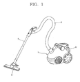
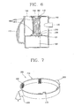
- Figure 1 is a perspective view showing a structure of a general vacuum cleaner.
- a general vacuum cleaner includes a cleaner main body 1 and a suction head 3 connected to the cleaner main body 1 by a suction hose 5 and an expansion pipe 4, for sucking dust and foreign substances from a floor.
- the cleaner main body 1 includes a suction force generating part (not shown) for generating a suction force; and a filter device 6 for collecting dust and foreign substances by a suction force generated from the suction force generating part.
- the filter device is provided with a knob 8 and detachably attached to the inside of the cleaner main body 1.
- a user can couple the filter device to the cleaner main body 1 or separate it therefrom by using the knob 8, more conveniently.
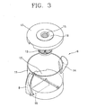
- Figure 3 is a disassembled perspective view showing a filter device of a conventional vacuum cleaner
- Figure 4 is a longitudinal sectional view showing a filter device of a conventional vacuum cleaner.
- the filter device 6 in accordance with the conventional art includes a casing 11 having a collecting space therein, a suction opening 14 through which air including dust is sucked and a discharge opening 15 through which purified air is discharged; and a filter 13 installed at the internal space of the casing 11, for filtering dust from air sucked through the suction opening 14.
- the casing 11 is formed in a cylindrical shape an upper side of which is opened and includes a cover 12 installed for covering an upper surface of the casing 11; a filter supporter 18 positioned at the cover 12 and having a discharge opening 15 formed penetratingly, though which air purified by the filter 13 is discharged outside; a support wall body 16 protruded from an inner lower portion of the casing 11 at a predetermined height; and a pair of blocking plates 17 installed at an upper surface of the support wall body 17 to face each other so that relatively big dust or foreign substances of dust introduced into the casing 11 are prevented from escaping therefrom.
- such a conventional vacuum cleaner has a problem in that the filter 13 has to be cleaned or replaced periodically. This is because when the vacuum cleaner is used for a certain period of time, fine dust is attached to the filter 13 of the filter device 6, thereby deteriorating a suction force. That is, since fine dust closes up a close mesh of the filter 13, it is difficult to discharge sucked air and finally a decrease in suction force Is caused. Accordingly, if the filter 13 is not periodically cleaned or replaced, a cleaning operation is not performed actively due to the deterioration of the suction force.
- EP-A-1 136 028 discloses a filter unit having a cylindrical filter brushed by a rotating cleaning member to remove dust, the cleaning member being driven by the flow of air from the inlet of the filter unit.
- an object of the present Invention Is to provide a filter device for a vacuum cleaner capable of preventing a channel of a filter from being closed, by removing fine dust attached to a filter in cleaning.
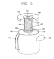
- Figure 5 is a partially cut-out perspective view of a filter device for a vacuum cleaner in accordance with a first embodiment of the present invention
- Figure 6 is a longitudinal sectional view of a filter device for a vacuum cleaner in accordance with a first embodiment of the present invention
- Figure 7 is a perspective view showing a rotary ring in accordance with the first embodiment of the present invention.
- a filter device for a vacuum cleaner in accordance with the present invention includes: a casing 100 having a collecting space therein, a suction opening 120 through which air including dust is sucked and a discharge opening 150 through which purified air is discharged; a filter 300 installed at the internal space of the casing 100, for filtering dust from air sucked through the suction opening 120; a filter cleaning unit 200 disposed at an outer circumferential surface of the filter 300, for cleaning the filter 300 by being rotated by movement of air sucked through the suction opening; and a rotation restraining means for restraining rotation of the filter cleaning unit 200 when the filter cleaning unit 200 reaches a top dead point.
- the casing 100 is formed in a cylindrical shape an upper side of which is opened and includes a cover 130 installed for covering the upper surface of the casing 100; a filter supporter 140 positioned at the cover 130 and having a discharge opening 150 formed penetratingly, through which air purified by the filter 300 is discharged outside; a support wall body 122 protruded from an inner lower portion of the casing 100 at a predetermined height; and a pair of blocking plates 121 installed at an upper surface of the support wall body 122 to face each other so that relatively heavy dust or foreign substances of dust introduced into the casing 100 are prevented from escaping therefrom.
- the suction opening 120 of the casing 100 is formed eccentrically at one side of the casing 100 so that introduced air and dust can be rotated in the casing 100.
- the filter 300 is formed in a cylindrical shape and is fixedly installed at a lower surface of the filter supporter 140, receiving the discharge opening 150 at its upper surface.
- the filter cleaning unit 200 includes: a rotary ring 210 disposed at an outer circumferential surface of the filter 300; a blade 220 mounted at an outer surface of the rotary ring 210, for rotating and lifting the rotary ring 210 by movement of air sucked through the suction opening 120; and at least one brush 230 mounted inside the rotary ring 210, for removing dust attached to a surface of the filter 300 by being rotated together with the rotary ring 210.
- the rotary ring 210 is made of a lightweight material so as to make rotation and lifting easy.
- the blade is inclined on the basis of an axial direction of the filter 300 so as to generate a rotation force and an ascending force.
- the brushes 230 are protruded from the inside of the rotary ring toward its center at regular intervals (in the drawing, regular intervals of 90°) therebetween.
- the rotation restraining means 400 includes a first stopper 410 protruded from an upper surface of the rotary ring 210; and a second stopper 420 formed at the filter supporter 140 connected to the filter 300, by which the first stopper 410 is caught.
- the first stopper 410 is protruded in a direction that the rotary ring 210 is rotated.
- the second stopper 420 is protruded from a lower side of the filter supporter 140 and has an insertion groove 421 in which the stopper 410 is inserted.
- An elastic member 425 for releasing the first stopper 410 from the insertion groove 421 when a cleaner stops operating is provided in the insertion groove 421.
- the elastic member is a coil spring.
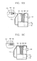
- Figure 9 is an operational view showing a process that a vacuum cleaner in accordance with the first embodiment of the present invention cleans a filter.
- the support wall body 122 prevents an eddy from occurring in a space under the blocking plate 121 to thereby prevent dust from floating again and being moved to a space above the blocking plate 121, and fine dust or foreign substances in air sucked through the suction opening 120 are purified again by the filter 300.
- the first stopper 410 provided at the upper end of the filter cleaning unit 200 is inserted in the second stopper 420 provided at the upper end of the filter 300 to restrain further rotation thereof so as to prevent the brush 230 of the filter cleaning unit 200 from cleaning the filter 300, excessively.
- the elastic member 425 a compression spring, is mounted in the second stopper 420 and maintains its state of being compressed by pressure of air.
- the filter cleaning unit rotates and ascends by a rotation force of air sucked into an internal space of the casing to thereby clean the outer circumferential surface of the filter. For this reason, flow resistance of air, which may occur when the outer circumferential surface of the filter is closed up with dust can be reduced even if the cleaner is operated for a long time. Accordingly, efficiency of the cleaner can be remarkably improved.
- Figure 10 is a perspective view showing a cleaning control part in accordance with a second embodiment of the present invention. The same structure and operation as the first embodiment will be omitted.
- the rotation control means 400 includes a first stopper 410 protruded from an upper surface of the rotary ring 210; and a second stopper 420 formed at the filter supporter 140 connected to the filter 300, by which the first stopper 410 is caught.
- the first stopper 410 is protruded in a direction that the rotary ring 210 is rotated and includes a magnetic body 412.
- the second stopper 420 is protruded from a lower side of the filter supporter 140 and includes an insertion groove 421 in which the first stopper 410 is inserted and a magnetic body 422 inserted in the insertion groove 421.
- a portion of the magnetic body 422 of the second stopper 420 and a portion of the magnetic body 412 of the first stopper 410, which face each other, have the same polarity so that when the cleaner is in operation, the first stopper 410 and the second stopper 420 meet each other by movement of a fluid, and if the cleaner is stopped, the first stopper 410 is distanced from the second stopper 420 by a magnetic force.
- the magnetic body 412, 422 is a permanent magnet.
- the filter cleaning unit 200 ascends to an upper end of the filter 300 by a rotation force and an ascending force of air sucked into the casing 100 to thereby brush and clean an outer circumferential surface of the filter 300.
- the first stopper 410 provided at an upper end of the filter cleaning unit 200 is inserted into the second stopper 420 provided at an upper end of the filter 300 so as to restrain further rotation. Accordingly, like the first embodiment, by preventing further rotation, the brush of the filter cleaning unit 200 is prevented from excessively cleaning the filter 300.
- the filter cleaning unit 200 When pressure of air is removed, the filter cleaning unit 200 is sprung instantly in a direction opposite to a direction that air rotates and is rotated by a repulsive force between the permanent magnet 412 mounted at the first stopper 410 and the permanent magnet 422 mounted at the second stopper 420, so that the first stopper 410 is separated from the second stopper 420 and descends to its initial position.
- Figure 11 is a longitudinal sectional view of a filter device for a vacuum cleaner in accordance with a third embodiment of the present invention
- Figure 12 is a partially cut-out perspective view of a filter device for a vacuum cleaner in accordance with a third embodiment of the present invention.
- the filter cleaning unit 200 in accordance with the present invention includes a rotary ring disposed at an outer circumferential surface of the filter 300; a brush supporter 215 connected to the rotary ring 210 and formed in an axial direction of the filter 300 almost as high as a height of the filter 300; a blade 220 formed at an outer surface of the brush supporter 215, for rotating the rotary ring by movement of air sucked through the suction opening 120; and a brush 230 mounted inside the brush supporter 215, for removing dust attached to the surface of the filter 300 by being rotated together with the rotary ring 210.
- the air rotating along a wall surface of the casing 100 collides against the blade 220 of the filter-cleaning unit 200 located at the outer circumferential surface of the filter 300, thereby inducing a rotation force.
- the filter cleaning unit 200 is rotated in a direction that air rotates so that the brush 230 brushes the outer circumferential surface of the filter 300 and continuously remove fine dust or filth from the filter 300.
- the filter cleaning unit 200 is rotated by a rotation force of air sucked into a certain space of the casing 100 to clean the outer circumferential surface of the filter 300. Therefore, even if the cleaner is operated for a long time, flow resistance of air, which may occur when dust is attached to the outer circumferential surface of the filter, is reduced to thereby remarkably improve efficiency of a cleaner.
- the outer circumferential surface of the filter is cleaned while a dust removing means rotates and ascends by a rotation force of air sucked into an internal space of the casing. Accordingly, even if the cleaner is operated for a long time, flow resistance of air, which may occur when dust is attached to the outer circumferential surface of the filter, is reduced to thereby remarkably increase efficiency of the cleaner.
Landscapes
- Chemical & Material Sciences (AREA)
- Chemical Kinetics & Catalysis (AREA)
- Engineering & Computer Science (AREA)
- Mechanical Engineering (AREA)
- Physics & Mathematics (AREA)
- Geometry (AREA)
- Nozzles For Electric Vacuum Cleaners (AREA)
- Filters For Electric Vacuum Cleaners (AREA)
Claims (10)
- Filtervorrichtung für einen Staubsauger, umfassend:- ein Gehäuse (100) mit einem darin befindlichen Sammelraum, einer Saugöffnung (120) zum Ansaugen von Staub enthaltender Luft, wobei die Saugöffnung exzentrisch an einer Seite des Gehäuses gebildet ist, so dass angesaugte Luft rotieren kann, und mit einer Auslassöffnung (150), durch welche gereinigte Luft ausgelassen wird,- einen im Innenraum des Gehäuses angebrachten Filter (300) zum Herausfiltern von Staub aus der durch die Saugöffnung angesaugten Luft, gekennzeichnet durch- eine an einer Außenumfangsfläche des Filters angeordnete Filterreinigungseinheit (200) zum Reinigen des Filters, indem sie durch die Bewegung der durch die Saugöffnung angesaugten Luft gedreht und angehoben wird, und- ein Drehhemmmittel (400) zum Hemmen der Drehbewegung der Filterreinigungseinheit, sobald die Filterreinigungseinheit eine obere Endstellung erreicht.
- Filtervorrichtung nach Anspruch 1, wobei die Filterreinigungseinheit (200) umfasst:- einen an einer Außenumfangsfläche des Filters (300) angeordneten Drehring (210),- einen an einer Außenfläche des Drehrings angebrachten Flügel (220) zum Drehen und Anheben des Drehrings infolge der Bewegung der durch die Saugöffnung (120) angesaugten Luft und- mindestens eine im Innern des Drehrings angebrachte Bürste (230) zum Entfernen an der Oberfläche des Filters anhaftenden Staubs, indem sie zusammen mit dem Drehring gedreht wird.
- Filtervorrichtung nach Anspruch 2, wobei der Drehring (210) aus einem Leichtmaterial gefertigt ist, das eine mühelose Drehung und Anhebung gestattet.
- Filtervorrichtung nach Anspruch 2, wobei der Flügel (220) gegenüber einer Axialrichtung des Filters (300) schräggestellt ist, um sowohl eine Drehkraft als auch eine Auftriebskraft zu erzeugen.
- Filtervorrichtung nach Anspruch 1, wobei das Drehhemmmittel (400) umfasst:- einen von einer Oberseite des Drehrings (210) vorstehenden ersten Stopper (410) und- einen zweiten Stopper (420), welcher so an dem mit dem Filter (300) verbundenen Filterhalter (140) gebildet ist, dass der erste Stopper von diesem gefangen wird.
- Filtervorrichtung nach Anspruch 5, wobei der erste Stopper (410) in Drehrichtung des Drehrings (210) absteht und der von einer Unterseite des Filterhalters (140) abstehende zweite Stopper (420) eine Einsetznut (421), in welche der erste Stopper eingesetzt ist, sowie ein in die Einsetznut eingesetztes elastisches Element (425) zum Freigeben des ersten Stoppers aus dem Eingriff mit der Einsetznut bei Stillsetzung des Staubsaugers aufweist.
- Filtervorrichtung nach Anspruch 6, wobei das elastische Element (425) eine Schraubenfeder ist.
- Filtervorrichtung nach Anspruch 5, wobei der erste Stopper (410) einen Magnetkörper (412) aufweist und der von einer Unterseite des Filterhalters (140) abstehende zweite Stopper (420) eine Einsetznut (421), in welche der erste Stopper eingesetzt ist, sowie einen in die Einsetznut eingesetzten Magnetkörper (422) umfasst, wobei einander zugewandte Teile des Magnetkörpers des ersten Stoppers und des Magnetkörpers des zweiten Stoppers gleiche Polarität besitzen, so dass im Betrieb des Staubsaugers der erste Stopper und der zweite Stopper infolge der Bewegung eines Fluids aufeinander treffen und bei Stillsetzung des Staubsaugers der erste Stopper sich infolge einer Magnetkraft von dem zweiten Stopper entfernt.
- Filtervorrichtung nach Anspruch 8, wobei der Magnetkörper (412, 422) ein Permanentmagnet ist.
- Filtervorrichtung nach Anspruch 1, wobei die Filterreinigungseinheit (200) umfasst:- einen an einer Außenumfangsfläche des Filters (300) angeordneten Drehring (210),- einen mit dem Drehring verbundenen Bürstenhalter (215), welcher in axialer Richtung des Filters eine Höhe besitzt, die fast so groß ist wie die Höhe des Filters,- einen an einer Außenfläche des Bürstenhalters gebildeten Flügel (220) zum Drehen des Drehrings infolge der Bewegung der Luft und- eine im Innern des Bürstenhalters angebrachte Bürste (230) zum Entfernen an der Oberfläche des Filters anhaftenden Staubs, indem sie zusammen mit dem Drehring gedreht wird.
Applications Claiming Priority (2)
| Application Number | Priority Date | Filing Date | Title |
|---|---|---|---|
| KR2004015925 | 2004-03-09 | ||
| KR1020040015925A KR100539762B1 (ko) | 2004-03-09 | 2004-03-09 | 진공청소기의 필터 청소 장치 |
Publications (2)
| Publication Number | Publication Date |
|---|---|
| EP1574160A1 EP1574160A1 (de) | 2005-09-14 |
| EP1574160B1 true EP1574160B1 (de) | 2008-10-22 |
Family
ID=34825189
Family Applications (1)
| Application Number | Title | Priority Date | Filing Date |
|---|---|---|---|
| EP04291984A Expired - Lifetime EP1574160B1 (de) | 2004-03-09 | 2004-08-03 | Filtereinrichtung für einen Staubsauger |
Country Status (5)
| Country | Link |
|---|---|
| US (1) | US7494520B2 (de) |
| EP (1) | EP1574160B1 (de) |
| KR (1) | KR100539762B1 (de) |
| CN (1) | CN100381094C (de) |
| DE (1) | DE602004017273D1 (de) |
Cited By (2)
| Publication number | Priority date | Publication date | Assignee | Title |
|---|---|---|---|---|
| CN106178724A (zh) * | 2016-09-06 | 2016-12-07 | 北京公共交通控股(集团)有限公司 | 用于车辆维保的除尘作业装置 |
| CN111530193A (zh) * | 2020-05-18 | 2020-08-14 | 毛嘉豪 | 一种建筑工地用管式除尘器 |
Families Citing this family (70)
| Publication number | Priority date | Publication date | Assignee | Title |
|---|---|---|---|---|
| KR100585692B1 (ko) * | 2004-04-06 | 2006-06-07 | 엘지전자 주식회사 | 진공청소기의 먼지통 |
| EP1743562B1 (de) * | 2005-07-13 | 2011-09-28 | Toshiba TEC Kabushiki Kaisha | Elektrischer Staubsauger |
| KR100804808B1 (ko) * | 2006-03-24 | 2008-02-20 | 삼성광주전자 주식회사 | 진공청소기의 사이클론 집진장치 |
| EP2032011B1 (de) * | 2006-06-02 | 2013-01-02 | Koninklijke Philips Electronics N.V. | Staubfilter und staubsauger mit einem derartigen filter |
| US8015657B2 (en) * | 2007-02-09 | 2011-09-13 | Black & Decker Inc. | Vacuum electronic power tool sense |
| GB2450717A (en) * | 2007-07-04 | 2009-01-07 | Black & Decker Inc | Power cutter including air filter cleaning mechanism |
| US8272134B2 (en) * | 2007-07-04 | 2012-09-25 | Black & Decker Inc. | Power cutter |
| GB2450720A (en) * | 2007-07-04 | 2009-01-07 | Black & Decker Inc | Power cutter with pleated filter |
| KR20090018482A (ko) * | 2007-08-17 | 2009-02-20 | 삼성광주전자 주식회사 | 집진장치 |
| US8516650B2 (en) * | 2007-10-11 | 2013-08-27 | Black & Decker Inc. | Vacuum electronic water sense circuit |
| US7962994B2 (en) * | 2007-10-11 | 2011-06-21 | Black & Decker Inc. | Vacuum electronic switch detection system |
| US7644469B2 (en) * | 2007-10-11 | 2010-01-12 | Black & Decker Inc. | Vacuum electronics isolation method |
| US8951319B2 (en) * | 2007-11-19 | 2015-02-10 | Lg Electronics Inc. | Air cleaner and controlling method thereof |
| KR101164335B1 (ko) * | 2007-12-26 | 2012-07-09 | 가부시끼가이샤 도시바 | 전기 청소기 |
| US8327487B2 (en) | 2008-01-31 | 2012-12-11 | Black & Decker Inc. | Vacuum filter cleaning device |
| US9510718B2 (en) | 2008-07-04 | 2016-12-06 | Emerson Electric Co. | Wet/dry vacuum cleaner filter for wet material collection |
| US8206482B2 (en) | 2008-07-04 | 2012-06-26 | Emerson Electric Co. | Vacuum appliance filter assemblies and associated vacuum systems |
| US9675225B2 (en) | 2008-07-04 | 2017-06-13 | Emerson Electric Co. | Filter cage for wet/dry vacuums |
| USD601318S1 (en) * | 2008-10-01 | 2009-09-29 | Emerson Electric Co. | Filter for a wet/dry vacuum cleaner |
| USD617065S1 (en) * | 2008-10-01 | 2010-06-01 | Emerson Electric Co. | Filter for a wet/dry vacuum cleaner |
| USD601319S1 (en) * | 2008-10-01 | 2009-09-29 | Emerson Electric Co. | Filter for a wet/dry vacuum cleaner |
| USD601320S1 (en) * | 2008-10-01 | 2009-09-29 | Emerson Electric Co. | Filter for a wet/dry vacuum cleaner |
| US9238451B2 (en) * | 2008-10-06 | 2016-01-19 | Shop Vac Corporation | Vacuum assembly with inlet through removable tank |
| KR101052107B1 (ko) * | 2008-10-10 | 2011-07-26 | 엘지전자 주식회사 | 진공 청소기 |
| US8167981B2 (en) * | 2009-04-21 | 2012-05-01 | Spx Corporation | Vacuum filter assembly |
| KR100931642B1 (ko) * | 2009-07-14 | 2009-12-14 | (주)성심 | 진공사이클론 집진기 |
| CN101984910A (zh) * | 2010-08-31 | 2011-03-16 | 孙大亮 | 吸尘器的滤网自动清洁刷 |
| US12171393B2 (en) | 2011-03-04 | 2024-12-24 | Omachron Intellectual Property Inc. | Surface cleaning apparatus |
| US11534043B2 (en) | 2011-03-04 | 2022-12-27 | Omachron Intellectual Property Inc. | Surface cleaning apparatus |
| DE102011088965A1 (de) | 2011-12-19 | 2013-06-20 | BSH Bosch und Siemens Hausgeräte GmbH | Filtervorrichtung, Verfahren und Computerprogramm zum Filtern von Partikeln |
| AU2013211519B2 (en) | 2012-08-08 | 2017-11-02 | Bissell Inc. | Solid fragrance carrier and method of use in a vacuum cleaner |
| TWI584773B (zh) * | 2013-03-14 | 2017-06-01 | 東芝生活電器股份有限公司 | 電吸塵器 |
| CN104665704A (zh) * | 2013-11-30 | 2015-06-03 | 镇江康元电器有限公司 | 一种吸尘器滤筒 |
| GB2524018B (en) * | 2014-03-11 | 2017-01-04 | Hoover Ltd | Cyclonic separation device |
| US11445873B2 (en) | 2014-12-17 | 2022-09-20 | Omachron Intellectual Property Inc. | Hand carryable surface cleaning apparatus |
| US11445874B2 (en) | 2014-12-17 | 2022-09-20 | Omachron Intellectual Property Inc. | Hand carryable surface cleaning apparatus |
| US9756999B2 (en) | 2014-12-22 | 2017-09-12 | Aktiebolaget Electrolux | Vacuum cleaner filtration system with filter cleaning mode |
| DE102015108558A1 (de) * | 2015-05-29 | 2016-12-01 | Vorwerk & Co. Interholding Gmbh | Luftfilter |
| KR102463056B1 (ko) * | 2015-10-21 | 2022-11-03 | 삼성전자주식회사 | 사이클론 집진장치 및 이를 포함하는 진공 청소기 |
| WO2017083497A1 (en) | 2015-11-10 | 2017-05-18 | Techtronic Industries Co. Ltd. | Handheld vacuum cleaner |
| GB2546542B (en) | 2016-01-22 | 2018-07-04 | Dyson Technology Ltd | Vacuum cleaner |
| GB2546541B (en) | 2016-01-22 | 2018-07-04 | Dyson Technology Ltd | Vacuum cleaning apparatus |
| GB2546543B (en) | 2016-01-22 | 2019-01-02 | Dyson Technology Ltd | Separating apparatus and vacuum cleaner |
| GB201603302D0 (en) * | 2016-02-25 | 2016-04-13 | Grey Technology Ltd | Dirt-collection chamber for a vacuum cleaner |
| GB2557304B (en) * | 2016-12-05 | 2022-06-01 | Beacon Group Int Ltd | A filter system and a vacuum cleaner incorporating a filter system |
| US10750915B2 (en) * | 2017-01-09 | 2020-08-25 | Emerson Electric Co. | Vacuum cleaning systems and methods including slide out drum and filter interlock device |
| WO2018232540A1 (es) * | 2017-06-21 | 2018-12-27 | Biodryingtech Spa | Ciclon acelerador separador de particulas solidas |
| US11219906B2 (en) | 2019-01-23 | 2022-01-11 | Omachron Intellectual Property Inc. | Surface cleaning apparatus, cyclonic air treatment member and surface cleaning apparatus including the same |
| US10966583B2 (en) * | 2019-01-23 | 2021-04-06 | Omachron Intellectual Property Inc. | Surface cleaning apparatus, cyclonic air treatment member and surface cleaning apparatus including the same |
| KR102438130B1 (ko) * | 2017-08-28 | 2022-08-31 | 삼성전자주식회사 | 공기청정기 |
| CN108553022A (zh) * | 2018-02-07 | 2018-09-21 | 江苏美的清洁电器股份有限公司 | 过滤结构和吸尘装置 |
| US11930987B2 (en) | 2018-04-20 | 2024-03-19 | Omachron Intellectual Property Inc. | Surface cleaning apparatus |
| US10595696B2 (en) | 2018-05-01 | 2020-03-24 | Sharkninja Operating Llc | Docking station for robotic cleaner |
| EP3823507B1 (de) | 2018-07-20 | 2025-04-16 | SharkNinja Operating LLC | Andockstation für ablagerungsentfernung bei einem reinigungsroboter |
| US10974258B2 (en) * | 2019-01-23 | 2021-04-13 | Omachron Intellectual Property Inc. | Surface cleaning apparatus, cyclonic air treatment member and surface cleaning apparatus including the same |
| US11129510B2 (en) * | 2019-01-23 | 2021-09-28 | Omachron Intellectual Property Inc. | Surface cleaning apparatus, cyclonic air treatment member and surface cleaning apparatus including the same |
| US11135602B2 (en) * | 2019-01-23 | 2021-10-05 | Omachron Intellectual Property Inc. | Surface cleaning apparatus, cyclonic air treatment member and surface cleaning apparatus including the same |
| US10925451B2 (en) * | 2019-01-23 | 2021-02-23 | Omachron Intellectual Property Inc. | Surface cleaning apparatus, cyclonic air treatment member and surface cleaning apparatus including the same |
| US11213832B2 (en) * | 2019-01-23 | 2022-01-04 | Omachron Intellectual Property Inc. | Surface cleaning apparatus, cyclonic air treatment member and surface cleaning apparatus including the same |
| CN113825436B (zh) | 2019-03-15 | 2023-02-17 | 奥马克罗知识产权有限公司 | 表面清洁设备 |
| AU2020289124B2 (en) * | 2019-06-05 | 2024-01-04 | Lg Electronics Inc. | Cleaner |
| KR102733608B1 (ko) * | 2019-11-29 | 2024-11-21 | 엘지전자 주식회사 | 청소기 |
| KR102739874B1 (ko) * | 2019-12-20 | 2024-12-05 | 엘지전자 주식회사 | 청소기 |
| WO2021246694A1 (ko) * | 2020-06-01 | 2021-12-09 | 엘지전자 주식회사 | 청소기 |
| US20230180980A1 (en) * | 2020-06-01 | 2023-06-15 | Lg Electronics Inc. | Cleaner |
| EP4215095A4 (de) * | 2020-09-18 | 2024-11-13 | Beijing Roborock Technology Co., Ltd. | Staubreinigungsmechanismus und reinigungsvorrichtung |
| CN113813673B (zh) * | 2021-09-28 | 2023-05-19 | 浙江开山恺雷滤清器有限公司 | 一种滤清器外网及其制备方法 |
| CN117883912B (zh) * | 2024-02-26 | 2025-01-28 | 四川省公路规划勘察设计研究院有限公司 | 暖风机通风过滤结构 |
| CN118416612B (zh) * | 2024-05-07 | 2024-10-18 | 天时建设集团有限公司 | 一种水泥窑尾中低硫烟气脱硫脱硝除尘装置及方法 |
| CN119175914A (zh) * | 2024-11-22 | 2024-12-24 | 靖江市奥祥交通设备制造有限公司 | 一种压力机用的除尘装置 |
Family Cites Families (11)
| Publication number | Priority date | Publication date | Assignee | Title |
|---|---|---|---|---|
| DE1004780B (de) * | 1954-07-06 | 1957-03-21 | Siemens Ag | Staubsauger mit selbsttaetiger Reinigungsvorrichtung fuer das aussen beaufschlagte Filter |
| US3145164A (en) * | 1960-02-12 | 1964-08-18 | Stamicarbon | Apparatus for wet-screening a mixture of fine abrasive particles |
| US3246754A (en) * | 1963-03-25 | 1966-04-19 | Sackett & Sons Co A J | Screen classifier with brush cleaners |
| US3778864A (en) * | 1972-04-10 | 1973-12-18 | W Scherer | Turbine powered surface vacuum cleaning device |
| GB1597332A (en) * | 1977-05-26 | 1981-09-03 | Weiss V | Filtering apparatus and methods of exchanging particulate filter materials |
| DE7733956U1 (de) * | 1977-11-04 | 1980-05-22 | Oberdorfer, Guido, 7919 Bellenberg | Filter eines reinigungsgeraetes |
| DE3823192A1 (de) * | 1988-07-08 | 1990-04-12 | Hein Lehmann Ag | Spaltrohrfilter |
| GB2293993B (en) * | 1994-09-30 | 1998-08-05 | John B Mckeown | Separation device |
| KR100413988B1 (ko) | 2000-03-24 | 2004-01-07 | 샤프 가부시키가이샤 | 전기 진공 청소기 |
| FR2836056B1 (fr) * | 2002-02-18 | 2005-02-04 | Aldes Aeraulique | Procede de decolmatage automatique du filtre d'un systeme d'aspiration centralise, dispositif pour ce procede et systeme d'aspiration centralise equipe d'un tel dispositif |
| KR100445808B1 (ko) * | 2002-02-28 | 2004-08-25 | 삼성광주전자 주식회사 | 진공청소기용 사이클론 집진장치 |
-
2004
- 2004-03-09 KR KR1020040015925A patent/KR100539762B1/ko not_active Expired - Fee Related
- 2004-08-03 EP EP04291984A patent/EP1574160B1/de not_active Expired - Lifetime
- 2004-08-03 DE DE602004017273T patent/DE602004017273D1/de not_active Expired - Lifetime
- 2004-08-06 US US10/912,038 patent/US7494520B2/en not_active Expired - Fee Related
- 2004-08-31 CN CNB2004100751079A patent/CN100381094C/zh not_active Expired - Fee Related
Cited By (2)
| Publication number | Priority date | Publication date | Assignee | Title |
|---|---|---|---|---|
| CN106178724A (zh) * | 2016-09-06 | 2016-12-07 | 北京公共交通控股(集团)有限公司 | 用于车辆维保的除尘作业装置 |
| CN111530193A (zh) * | 2020-05-18 | 2020-08-14 | 毛嘉豪 | 一种建筑工地用管式除尘器 |
Also Published As
| Publication number | Publication date |
|---|---|
| KR20050090719A (ko) | 2005-09-14 |
| CN100381094C (zh) | 2008-04-16 |
| CN1666702A (zh) | 2005-09-14 |
| EP1574160A1 (de) | 2005-09-14 |
| KR100539762B1 (ko) | 2006-01-10 |
| US7494520B2 (en) | 2009-02-24 |
| US20050198766A1 (en) | 2005-09-15 |
| DE602004017273D1 (de) | 2008-12-04 |
Similar Documents
| Publication | Publication Date | Title |
|---|---|---|
| EP1574160B1 (de) | Filtereinrichtung für einen Staubsauger | |
| AU2004212623B2 (en) | Filtering device for vacuum cleaner | |
| US7785381B2 (en) | Dust collecting apparatus with combined compacting and filter cleaning for a vacuum cleaner | |
| RU2230477C2 (ru) | Циклонный пылесборник пылесоса | |
| KR20080097104A (ko) | 진공청소기용 집진장치 | |
| US8870988B2 (en) | Dust collector for a vacuum cleaner having a dust removal function | |
| WO2001005291A1 (en) | Vacuum cleaner | |
| CN105361815A (zh) | 过滤器振动装置及其自清洁方法及吸尘器 | |
| US20240398190A1 (en) | Filter assembly, vacuum cleaner and cleaning set | |
| CN219920958U (zh) | 一种清洁设备及清洁系统 | |
| CN211299802U (zh) | 尘杯组件和吸尘器 | |
| CN211559935U (zh) | 智能扫地机器人滤网主动除尘防堵塞系统及其扫地机器人 | |
| CN111938499A (zh) | 一种减振降噪吸尘器 | |
| CN110613400A (zh) | 一种旋风分离组件、集尘杯体及除螨清洁设备 | |
| CN216754345U (zh) | 过滤器自清洁装置与吸尘器 | |
| CN211562202U (zh) | 一种高效环保粉尘处理设备 | |
| CN102772169A (zh) | 一种具有压缩功能的集尘装置及其控制方法 | |
| JP2004024887A (ja) | 電気掃除機 | |
| CN214972632U (zh) | 一种便携式滤筒式除尘机 | |
| CN111449566B (zh) | 手持式吸尘器 | |
| CN112656293B (zh) | 一种尘污分离装置及吸尘器 | |
| CN112656286B (zh) | 一种尘污分离装置及吸尘器 | |
| CN211609605U (zh) | 吸尘器旋风过滤装置 | |
| WO2024244116A1 (zh) | 一种过滤组件、吸尘器和清洁套装 | |
| JP2013085590A (ja) | 電気掃除機 |
Legal Events
| Date | Code | Title | Description |
|---|---|---|---|
| PUAI | Public reference made under article 153(3) epc to a published international application that has entered the european phase |
Free format text: ORIGINAL CODE: 0009012 |
|
| AK | Designated contracting states |
Kind code of ref document: A1 Designated state(s): AT BE BG CH CY CZ DE DK EE ES FI FR GB GR HU IE IT LI LU MC NL PL PT RO SE SI SK TR |
|
| AX | Request for extension of the european patent |
Extension state: AL HR LT LV MK |
|
| 17P | Request for examination filed |
Effective date: 20050905 |
|
| AKX | Designation fees paid |
Designated state(s): DE FR GB |
|
| 17Q | First examination report despatched |
Effective date: 20070118 |
|
| GRAP | Despatch of communication of intention to grant a patent |
Free format text: ORIGINAL CODE: EPIDOSNIGR1 |
|
| GRAS | Grant fee paid |
Free format text: ORIGINAL CODE: EPIDOSNIGR3 |
|
| GRAA | (expected) grant |
Free format text: ORIGINAL CODE: 0009210 |
|
| AK | Designated contracting states |
Kind code of ref document: B1 Designated state(s): DE FR GB |
|
| REG | Reference to a national code |
Ref country code: GB Ref legal event code: FG4D |
|
| REF | Corresponds to: |
Ref document number: 602004017273 Country of ref document: DE Date of ref document: 20081204 Kind code of ref document: P |
|
| PLBE | No opposition filed within time limit |
Free format text: ORIGINAL CODE: 0009261 |
|
| STAA | Information on the status of an ep patent application or granted ep patent |
Free format text: STATUS: NO OPPOSITION FILED WITHIN TIME LIMIT |
|
| 26N | No opposition filed |
Effective date: 20090723 |
|
| REG | Reference to a national code |
Ref country code: FR Ref legal event code: PLFP Year of fee payment: 12 |
|
| REG | Reference to a national code |
Ref country code: FR Ref legal event code: PLFP Year of fee payment: 13 |
|
| REG | Reference to a national code |
Ref country code: FR Ref legal event code: PLFP Year of fee payment: 14 |
|
| PGFP | Annual fee paid to national office [announced via postgrant information from national office to epo] |
Ref country code: FR Payment date: 20170830 Year of fee payment: 14 |
|
| PG25 | Lapsed in a contracting state [announced via postgrant information from national office to epo] |
Ref country code: FR Free format text: LAPSE BECAUSE OF NON-PAYMENT OF DUE FEES Effective date: 20180831 |
|
| PGFP | Annual fee paid to national office [announced via postgrant information from national office to epo] |
Ref country code: DE Payment date: 20190705 Year of fee payment: 16 |
|
| PGFP | Annual fee paid to national office [announced via postgrant information from national office to epo] |
Ref country code: GB Payment date: 20190708 Year of fee payment: 16 |
|
| REG | Reference to a national code |
Ref country code: DE Ref legal event code: R119 Ref document number: 602004017273 Country of ref document: DE |
|
| GBPC | Gb: european patent ceased through non-payment of renewal fee |
Effective date: 20200803 |
|
| PG25 | Lapsed in a contracting state [announced via postgrant information from national office to epo] |
Ref country code: DE Free format text: LAPSE BECAUSE OF NON-PAYMENT OF DUE FEES Effective date: 20210302 |
|
| PG25 | Lapsed in a contracting state [announced via postgrant information from national office to epo] |
Ref country code: GB Free format text: LAPSE BECAUSE OF NON-PAYMENT OF DUE FEES Effective date: 20200803 |