EP1573307B1 - Piezoelektrische sensoranordnung - Google Patents
Piezoelektrische sensoranordnung Download PDFInfo
- Publication number
- EP1573307B1 EP1573307B1 EP03781230.2A EP03781230A EP1573307B1 EP 1573307 B1 EP1573307 B1 EP 1573307B1 EP 03781230 A EP03781230 A EP 03781230A EP 1573307 B1 EP1573307 B1 EP 1573307B1
- Authority
- EP
- European Patent Office
- Prior art keywords
- flow cell
- cell element
- sensor
- crystal
- sensor arrangement
- Prior art date
- Legal status (The legal status is an assumption and is not a legal conclusion. Google has not performed a legal analysis and makes no representation as to the accuracy of the status listed.)
- Expired - Lifetime
Links
Images


Classifications
-
- G—PHYSICS
- G01—MEASURING; TESTING
- G01N—INVESTIGATING OR ANALYSING MATERIALS BY DETERMINING THEIR CHEMICAL OR PHYSICAL PROPERTIES
- G01N29/00—Investigating or analysing materials by the use of ultrasonic, sonic or infrasonic waves; Visualisation of the interior of objects by transmitting ultrasonic or sonic waves through the object
- G01N29/02—Analysing fluids
- G01N29/036—Analysing fluids by measuring frequency or resonance of acoustic waves
-
- G—PHYSICS
- G01—MEASURING; TESTING
- G01N—INVESTIGATING OR ANALYSING MATERIALS BY DETERMINING THEIR CHEMICAL OR PHYSICAL PROPERTIES
- G01N2291/00—Indexing codes associated with group G01N29/00
- G01N2291/02—Indexing codes associated with the analysed material
- G01N2291/025—Change of phase or condition
- G01N2291/0256—Adsorption, desorption, surface mass change, e.g. on biosensors
Definitions
- the present invention relates to a piezoelectric sensor arrangement, a sensor element and a flow cell element to be used in the sensor arrangement.
- a Quartz Crystal Microbalance (QCM) system utilizes the piezoelectric effect of a quartz crystal.
- a quartz crystal that is placed between two electrodes, which are connected to an AC-potential, begins to oscillate if the frequency of the AC-potential is close to the resonance frequency of the oscillation mode for the quartz crystal.
- the resonance frequency of the quartz crystal is a function of many parameters, such as temperature, pressure, cut angel of the crystal, mechanical stress and thickness of the crystal.
- Typical resonance frequencies used in liquid applications range from 1 MHz to 50 MHz.
- the crystal is normally AT-cut with a circular or quadratic shape with a diameter of approximately 5-10 mm.
- the electrodes are normally of gold on both sides, but other metals are not unusual. The electrodes are very thin compared to the quartz crystal plate and can therefore be considered as part of the crystal plate.
- the mass resolution of a QCM system can be as low as 1 pg/cm 2 , corresponding to less than 1 % of a monolayer of hydrogen.
- a typical QCM piezoelectric system comprises a sensor unit, a sample insertion unit, a frequency counter, and signal presentation equipment and buffer and waste containers.
- a sample which can contain any chemical substance of interest, is introduced into the sensor unit by the sample insertion unit.
- the sensor unit contains a piezoelectric resonator, a sensor chamber, flow channels to and from the chamber and an oscillating circuit.
- the sample induces an interaction with the piezoelectric sensor surface, which can in turn be observed by monitoring the oscillating characteristics of the crystal plate, e.g. by measuring changes in the piezoelectric resonator frequency.
- the resonator utilised by the sensor unit includes a crystal plate, which is a plane piezoelectric crystal.
- the crystal plate is provided with electric contact areas for an electrode and a counter electrode on its surface, which electrodes are connectable to a signal source (e.g. an alternating voltage source) as well as to a measurement device.
- a signal source e.g. an alternating voltage source
- the piezoelectric crystal plate is on one side brought into contact with the liquid sample to be examined.
- the crystal responds to the accumulation of the mass of the substance to be detected or to a change in the physical properties of the sample by altering its resonance frequency and/or oscillation amplitude.
- Piezoelectric sensors can be used for analysis of the viscosity of a liquid sample and are particularly suitable for studying chemical and biochemical interactions. If a piezoelectric sensor is to be used for the latter purpose, the electrode that is to be exposed to the sample is provided with a specific surface coating, which will interact with the sample. Such surface coated piezoelectric sensors can be used within for example surface science, biotechnology research and pharmaceuticals development. Other applications can be as sensor for detection of hazardous gases or substances such as environmental contaminants, biochemical warfare agents and illicit drugs, e.g. narcotic substances or performance improving drugs (doping).
- a third area for application of the technology is health diagnostics, where the sensor can be used for examining patients for different diseases by analysis of human blood or other body fluids. The use of piezoelectric resonators in these areas has up to now not gained a commercial acceptance, due to the drawbacks of the hitherto available systems.
- the crystal plates utilised by piezoelectric resonators are usually small oscillator quartz crystal plates.
- the resonating behaviour of the resonator may be impaired, i.e. by mechanical tension in the small plates caused by the holding carriers or by contacting with electric lines.
- piezoelectric resonators are advantageously used as active sensor elements, e.g. for detecting a substance in a medium, for instance, for measuring the concentration of the substance in a liquid.
- the oscillator quartz to be electrically contacted has also to be insulated liquid-tight against the to-be-examined liquid in order to prevent electric short circuits.
- Such a sensor is described in EP 453 820 B1 . This sensor provides a small oscillator quartz plate, which is clamped on both sides between two silicon seals and, in addition, is contacted to conductive adhesive substances.
- the piezoelectric resonators are provided with contact areas, which are to be connected to an electrical oscillation circuit and respectively to a measuring system, for electrical contacting on both its front side as well as on its rear side.
- the integration of the piezoelectric resonator in a casing with respective electric contacting is difficult and time consuming.
- Holding means of this type are also called flow-through cells, which are a unit, in which the already electrically contacted small oscillator quartz plate is connected to the connecting electrodes. Furthermore, defined supply and drain channels are provided via which the sample can be selectively supplied to the piezoelectric resonator and drained again.
- flow-through cells of this type the user needs much time and manual skill in replacing the crystal. In particular, in the field of biosensors, replacement often becomes necessary, because each different substance to be detected requires a specially prepared flow-through cell. In an attempt to overcome these problems the resonator has been integrated in a flow-through cell, as described in US 6 196 059 . However, even though such an integrated flow-through cell may be easy to handle, it has to be manufactured with high precision.
- Another drawback is that the surface coating of the electrode area has to be performed before gluing the resonator to the flow cell and the entire flow cell must be disposed of after use. In addition, there is a risk that the gluing process may interact with the surface coating and disable the desired functionality of the surface coating.
- JPH0875628 discloses a flow cell element for use in a piezoelectric arrangement as defined in the preamble of claim 1.
- the flow cell is formed by a cut out portion of the silicone sheet, by an upper glass plate and by the lower quartz crystal and the crystal holder.
- the cut out portion has two bulging extensions, which extend beyond the quartz crystal to the inlet and outlet channels formed in the lower crystal holder.
- the article Masson et al.: "Quartz Crystal Microbalance Bioaffinity Sensor for Biotin” (Anal. Chem., 1995, vol.67, No. 13, p.2212-2215 ) discloses a piezoelectric sensor arrangement, in which the quartz crystal is screwed against a flow cell element by means of an outer thread of the crystal holder and a corresponding inner thread of the holder of the flow cell element.
- the object of the present invention is to provide a piezoelectric sensor arrangement that gives reliable analysis results, has inexpensive disposable parts and is easy to handle.
- the object of the present invention is achieved by a piezoelectric sensor arrangement as defined in claim 8, in which inter-related parts interact so as to form a flow cell.
- the first of the inter-related parts is a sensor element, which holds a piezoelectric crystal.
- the second of the inter-related parts is a flow cell element, which comprises a recess through which the sample is to be led during use and which is made of an elastic material.
- the recess has extensions, in which the inlet and outlet fluid channels are arranged.
- Both inter-related parts are designed so that, when brought together before the analysis, the recess of the flow cell element is covered by the crystal of the sensor element thus forming a flow cell.
- the inter-related parts are held together only by means of a pressing force, and thus no adhesives or mechanical fixing means are needed. Since the flow cell element is made of an elastic material, the flow cell element is capable of sealing against the crystal, without breaking it.
- the present invention thus provides a piezoelectric sensor arrangement for analysis of fluid samples as defined in claim 8, which includes a signal source, a measuring device and a docking system, which comprises a first part and a second part.
- the second part comprises fluid channels for the sample and said first and second parts are movable in relation to each other between a closed position and an open position.
- the first part is provided with means for receiving a sensor element, which exposes a piezoelectric quartz crystal having a freely accessible electrode, which is intended to come into contact with the fluid sample.
- This means comprises an opening through which the crystal of the sensor element can come into contact with a flow cell element.
- the second part comprises fluid channels for the sample and a flow cell element that comprises an abutting part, which is provided with an outwardly open recess, and inlet and outlet fluid channels for leading a fluid through the recess.
- the recess is surrounded by an abutting surface.
- the flow cell element is made of an elastic material, which is capable of sealing against the piezoelectric quartz crystal.
- the first and second parts are arranged such that when the first and second parts are moved from the open position to the closed position, the abutting surface of the abutting part of the flow cell element comes into abutment with the exposed piezoelectric quartz crystal of the sensor element whereby in the closed position the piezoelectric quartz crystal sealingly covers the recess of the flow cell element thus creating a flow cell.
- the present invention also relates to a flow cell element as defined in claim 1.
- the piezoelectric sensor arrangement of the present invention is intended to be a part of an analysis system, which is shown in Fig. 1 , for sensing chemicals and chemical reactions in liquids.
- an analysis system comprises a computer (PC) 1 for controlling and presenting data, a frequency counter 2, a sample insertion unit 3, a sensor arrangement 4, a buffer solution container 5 and a waste container 6.
- PC computer
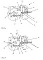
- Fig. 2a and 2b show a piezoelectric sensor arrangement 4 according to a preferred embodiment of the invention.
- the arrangement comprises a docking system, which includes a first part 8 provided with means 9 for receiving a sensor element 10 and a second part 11, 12, which comprises fluid channels 13 for the sample and a flow cell element 14.
- the flow cell element is preferably removable, but a piezoelectric sensor arrangement without the flow cell element is not covered by the claims.
- the first and second parts are movable in relation to each other between a closed position ( Fig. 2a ) and an open position ( Fig. 2b ).
- the sensor element 10 exposes a piezoelectric quartz crystal plate 32 (see Fig. 3 ) that is partially coated with electrode material on both sides.
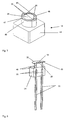
- the removable flow cell element 14 which is shown separately in Fig 7 , comprises a recess 45 and inlet and outlet fluid channels 46 for leading the sample fluid through the recess.
- the recess 45 is provided in an abutting part 43 of the flow cell element and is surrounded by an abutting surface 48.
- the flow cell element is made of an elastic material, which is elastic enough to seal against the piezoelectric quartz crystal without breaking it.
- the first part 8 and the second part 11, 12 of the sensor arrangement are arranged such that, when the first and second parts are moved from the open position to the closed position, the upper surface 48, which is the abutment surface of the abutment part 43 comes into abutment with the exposed piezoelectric quartz crystal 32 of the sensor element 10, whereby the recess 45 is sealingly covered by the piezoelectric quartz crystal 32 in the closed position, thus forming a flow cell by the flow cell element and the quartz crystal.
- the parts of the flow cell i.e.
- the piezoelectric crystal and the abutting part 43 of the flow cell element, with its recess 43, are held together only by means of a pressing force, exerted by the first and second parts (8; 11, 12) of the sensor arrangement as will be described in further detail below, and thus no adhesives or mechanical fixing means are needed.
- the design of the flow cell element will be described in greater detail below.
- the arrangement further includes a signal source 15, for transmitting electrical signals to the electrodes.
- the signal source and the electrodes form an electric circuit and the oscillation characteristics of the crystal plate 32 is monitored by a measuring device that is connected to the signal source, e.g. by measuring the changes in crystal resonance frequency.
- the sensor element receiving means 9 has a cavity, which is externally accessible via a slot 16, and through which slot the sensor element 10 can be inserted. It is also provided with an opening 17 through which the crystal plate of the sensor element can come into contact with the flow cell element 14. In the bottom of receiving part 9 a drainage hole is preferably provided, to avoid flooding should a leakage occur.
- the first part 8, i.e. the sensor receiving part, of the docking system of the sensor arrangement is preferably arranged as a movable part, slidably mounted to the second part 11, 12, which is then fixed.
- the sensor receiving 8 part can thus be slidably moved with relation to the second part 11, 12, between the open position and the closed position, in which the quartz crystal plate 32 comes into abutment with the flow cell element in the second part 11, 12.
- the second part 11, 12 may be arranged as a movable part, whereas the first part 11 is fixed.
- the second part 11, 12 of the arrangement in its turn includes one sample providing part 11 and one operating part 12.
- the sample providing part has a recess 18 into which the flow cell element 14 is inserted.
- the recess is adapted so as to correspond to the dimensions of an insertion part 44 of the removable flow cell element 14 that is directed away from the sensor element.
- Preferably the dimensions of the recess 18 are slightly smaller than the insertion part 14 so that the flow cell element is retained by friction.
- the flow cell element may also be attached by screws or other mechanical means.
- the sample providing part has two through-bores 19 for conduction of the sample to and from the flow cell. The through-bores are externally accessible at one end and lead to the bottom of the recess 18 at their other end.
- Flow channel tubing 13 can advantageously be inserted into the through-bores and be arranged to extend out into the recess 18 so that the tubing is partially inserted into the flow channels 46 of the flow cell element 14.
- the sample is supplied to the flow channel by means of a pressure differential between the inlet and the outlet of the flow channels.
- the pressure differential can be achieved by a syringe or a pump.
- the flow channel tubing is made of a material that is inert to the sample, such as PEEK or stainless steel and has an internal diameter of 0.1-1 mm.
- the sample providing part is also provided with electrical contacts 22 for connection with electrical contact areas on the sensor element.
- the contacts are preferably spring loaded contacting pins, with a spring force of 10-200 g, preferably 25-75 g.
- the operating part 12 includes an operating screw 23 which is connected to the sensor receiving part 8 by thread engagement and which is operated by a handle 24 that is fastened to the screw.
- the operating part 12 has a cavity 25, which fits a nut 26.
- the operating screw 23 is attached to the operating part 12 in such a manner that it can rotate without any axial motion with relation to the operating part.
- the threads of the screw engage internal threads of a bore 27 in the sensor element receiving part 8.
- the movement can be performed either manually or automatically with a motor and an electronic control system. It is important that the positioning of the piezoelectric crystal against the flow cell element is very accurate.
- the sensor element receiving means 9 may be mounted on three guide rods 28, which are spring loaded by means of springs 29 and steered by slide bearings 30 in the operating part 12, guided between the closed and open positions by means of along a linear path.
- the threads of the screw 23 and the bore 27 have a very low pitch, which enables a very exact adjustment of the force with which the crystal plate is pressed against the flow cell element.
- the pressing force of the crystal plate on the flow cell element should be as low as possible, so as to avoid excessive dampening of the crystal plate, but must be high enough to sufficiently seal the flow cell, i.e. that no sample leakage occurs.
- the force is dependent on the material hardness of the material chosen for the flow cell element and can be determined experimentally by running the sensor arrangement with a test sample of the desired fluid intended for use in the analysis, e.g. water.
- the operating part 12 of the sensor arrangement may preferably also be provided with a locking device that locks the screw as it reaches the position in which the crystal abuts the flow cell element with the empirically determined appropriate force.
- a locking device may consist of a spring-loaded locking pin on the nut 26 that enters a slot in the screw 23.
- a hydraulic or pneumatic cylinder may be used for the movement of the sensor receiving part.
- the sensor arrangement may be constructed as a multi-channel system, having several flow cells, each of them formed by abutment of a crystal plate and a flow cell element.
- the sensor arrangement includes one sensor element receiving means 9 per flow cell and corresponding flow cell elements for each sensor element.
- a number of crystal plates may be provided on a single sensor element, each crystal plate having a corresponding flow cell element on the sample providing part.
- the flow cell element may also be shaped so as to comprise several flow cell recesses, each having separate inlet and outlet channels.
- the flow cells may be coupled in parallel or in series. If the flow cells are coupled in parallel, a number of parallel sensor runs may be performed simultaneously.
- the crystal plates of the different flow cells may have different specific coating, thereby giving an opportunity to detect different substances in the sample. This is particularly practical if the flow cells are coupled in series.
- the sensor arrangement may optionally be provided with electromagnetic shielding and means for regulating the temperature.
- a sensor element to be used in the sensor arrangement is shown in Figs. 3 and 4 .
- the sensor element comprises a carrier 31 to which a piezoelectric quartz crystal plate 32 is attached.
- the carrier has the shape of a plate and has a surface area of 1-100 cm 2 , preferably 5-30 cm 2 and more preferably 10-20 cm 2 .
- the thickness of the carrier is 0,5-10 mm.
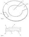
- the crystal that is attached to the carrier is shown without the carrier in Figs. 5 and 6 , and has a front side 32 and a rear side (not shown).
- the front side 32 is intended to come into contact with the fluid sample and is provided with a front electrode 33 and the rear side is provided with a rear electrode, which functions as a counter electrode.
- the electrodes are preferably made of gold.
- Both electrodes are adapted to receive electric signals for generation of an oscillating motion of the crystal.
- the crystal is arranged on the carrier in such a manner that the front side of the crystal 32 and the front electrode 33 are freely accessible for contact with the sample, whereas the counter electrode is directed towards the carrier plate, such that it does not come in contact with the sample.
- the carrier consists of a single rectangular plate, which has a smooth surface that is substantially flat.
- the carrier comprises a front part 34 and a rear part 35, between which the crystal 32 is attached. Both parts have the same width and length and the front part is provided with an opening 36 for exposure of the crystal to the sample and is also provided with apertures, which expose electrical contacting areas 37 that are thus externally accessible for the electrical contacts 22 on the sample providing part.
- the carrier comprises a recess or opening in the area of the rear electrode, so as to allow free oscillation of the crystal. If the carrier comprises an opening the electrodes may also be electrically contacted from the rear side of the crystal.
- the recess or opening is designed such that the carrier supports the periphery of the piezoelectric crystal from the rear side when it is pressed against the flow cell element. This supporting feature of the carrier further balances the sealing forces exerted by the flow cell element on the crystal plate, when it is subjected to the pressing forces of the abutment with the flow cell element.
- the carrier is preferably also provided with an aperture 38 for insertion of a locking pin, which is intended to ensure the correct position of the sensor element in the receiving means.
- each electrode 33 is smaller than the surface area of the crystal, preferably 10-90% of the crystal area.
- each side of the crystal comprises an area between the electrode edge and the crystal periphery that is not covered by electrode material.
- a connecting portion 33a of the electrode extends towards the crystal periphery thus presenting a conductive but not oscillating extensions of the electrode.
- Both electrodes 33 are electrically connectable to external contacts 22, by their connection portions 33a.
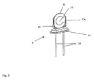
- the crystal plate is held by a holder 7, which also provides electrical contact between the electrodes and the electrical contacts 22 on the sample providing part, via contacting legs 39.
- the crystal with the holder is also shown in Fig. 5 .
- the holder comprises two metal holding plates 40, having an aperture into which the periphery of the crystal is inserted. In order to improve the electrical contact additionally, the holding plates may also be soldered to the electrodes.
- the holding plates are attached to a mounting plate 41 and electrically connected to the contacting legs 39.
- the holding plates 40 and their respective contacting leg 39 are preferably made in one piece.
- the holder 7 with the crystal is arranged on the carrier such that the contacting legs can be directly contacted by the electrical contacts 22 of the sample providing part.
- the carrier is provided with recesses that can partly receive the holder, so that the crystal is supported by the flat surface of the carrier plate.
- both parts are provided with recesses for the holder.
- the apertures in the front part are located right in front of the contacting legs 39 so that the electrical contacts 22 of the sample providing part can come in contact with the contacting legs.
- the crystal plate is attached directly to the carrier, i.e. no holder is used.
- the crystal plate is attached to the carrier e.g. by means of an adhesive if a single plate carrier is used. If a double plate carrier is used the crystal plate may be clamped between the rear and front parts of the carrier with additional use of adhesive attachment if desired.
- the adhesive does not impair the detection, since it has no sealing function and is applied to the side of the crystal plate that does not come in contact with the sample.
- the use of an adhesive or of clamping means in this embodiment of the present invention is thus not to compare with the use of adhesives or clamping that has the purpose to fix the crystal to the flow cell element means, which is disclosed in prior art.
- the contacting of the electrodes on the crystal surface is then performed by direct contact of the electrical contacts 22 of the sample providing part.
- This can be achieved by arranging the electrical contacts 22 such that they can reach the crystal surface by using spring-loaded contacting pins that can contact directly to the electrode surfaces, via the connecting portion 33a, with a limited force.
- spring-loaded contacting pins are commercially available.
- the electrodes may have a special design that enables direct contacting with contacting pins.
- One of the electrodes 42 is thus, as is shown in Fig.
- the contacting area 42a of one of the electrodes is situated on the opposite side of the crystal plate and on the same side as the other electrode 33. This makes it possible to contact both electrodes 33, 42 from one side of the crystal plate.
- the electrodes can be contacted electrically from the front side of the crystal plate, i.e. flow cell side, or from the rear side, i.e. the counter electrode side. Contacting the electrodes on the rear side has the advantage that there is more space available for the contacting pins on the non-fluid side of the crystal.
- the carrier has an opening which exposes also the rear side of the crystal and the spring-loaded electrical contacts are provided on the operating part. The crystal will thus be docked from both sides.
- the electrodes are, however, most advantageously contacted on the flow cell side of the crystal. This enables a less complicated construction of the sensor arrangement, since the crystal plate only has to be docked from the front side.
- the arrangement thus contains less movable parts. There is little space for the electrical contacts 22 to reach the contacting areas of the electrodes.
- the electrical connecting portion 33a of the electrode on the flow cell side is designed so as to reach the periphery of the crystal and if desired also around the crystal edge.
- the spring-loaded electrical contact pins can then more easily be contacted with the conductive but not oscillating extensions of the electrodes on the periphery of the crystal.
- the carrier has a printed conducting pattern that connects the electrodes to the electrical contacting areas 37.
- the sensor arrangement of the present invention is particularly useful for detection of chemical substances and chemical interactions/reactions, especially in biochemical applications.
- the front electrode 33 on the front side of the crystal is then coated with an active substance that is specific to the substance or the reaction to be analysed.
- the surface coating can be applied on the electrode surface prior to the attachment of the crystal plate to the carrier, but may also be performed after the attachment, which may be advantageous in some applications.
- the sensor element is preferably provided with a protective cover, such as a removable protective foil, that is arranged so as to cover the crystal and thus to protect the electrode surface from dirt and mechanical damage.
- a protective cover such as a removable protective foil
- the protective foil may be arranged such that it is peeled off as the sensor element is inserted into the receiving means.
- the protective foil is preferably resealable.
- a sliding cover may be used, which is arranged such that is it shoved aside when the sensor element is inserted into the sensor element receiving means of the sensor arrangement in connection with an analysis run.
- the sliding cover is preferably arranged in the sensor element in connection with actuating resilient means, which forces the cover back to the closed position when the sensor element is removed from the sensor arrangement after analysis.
- This arrangement additionally protects the user from coming into contact with the sample, which is a particular advantage when the sensor arrangement is used for analysis of samples that might be infectious, e.g. blood samples.
- the flow cell element 14 comprises an abutting part 43 and an insertion part 44 on top of each other.
- the abutting part has the geometry of a cylinder, having a cross section that substantially corresponds to the geometry of the electrode 33.
- the cross section of the abutting part must be smaller than the opening 36 in the front part of the sensor element, so that the abutting part can be inserted into the opening 36 and thus reach the crystal plate.
- the insertion part 43 of the flow cell element is has also the geometry of a cylinder, the cross section of which has a shape that is adapted to the bottom of recess 18 in the sample providing part of the sensor arrangement.
- the cross section of the insertion part 43 and may be of any shape, as long as it corresponds to the recess 18.
- the cross section is such that the flow cell element only can be inserted into the recess such that the inlet and outlet channels 46 are placed just in front of the fluid channels 13.
- the insertion part should be slightly larger than the recess, so that the flow cell element may be retained by friction.
- the base of the insertion part may for example rectangular.
- the abutting part 43 and the insertion part 44 are made in one piece.
- the abutting part 43 of the flow cell element 14 is provided with an outwardly open recess 45 and inlet and outlet fluid channels 46 by means of which a fluid sample can be lead through the recess.
- the recess 45 is surrounded by an abutting surface 48 and has a bottom that is a flat surface.
- the surface 48 is constituted by a ridge 47 that has a smooth upper surface, i.e. the abutting surface 48.
- the depth of the recess 45, i.e. the height of the ridge is 0,01-05 mm, preferably 0,05-0,2 mm.
- the smooth upper surface 48 of the ridge has a width of 0,05-1 mm.
- the whole flow cell element is made in one piece of elastic material, since this simplifies the manufacture of the flow cell element.
- the choice of material for the flow cell element with respect of its elasticity is very important for the performance of the piezoelectric sensor arrangement.
- a too stiff material may break the crystal or cause leakage of the flow cell created.
- a material that is too soft may cause irreproducible flow cell geometries, due to insufficient mechanical stability in the elastic material, and may dampen the crystal oscillation excessively.
- the surface roughness of the crystal surface 32 affects the elasticity required to efficiently seal the flow cell, as well as the surface roughness of the abutting surface 48. Rougher surfaces require a more elastic material.
- the chemical surface properties of the flow cell i.e.
- the chemical surface properties of the crystal surface, the chemical properties of the fluid used in the system and the elastic material itself, have an influence on the choice of elastic material element.
- a polar fluid such as water
- the pressure drop throughout the system also influences the elasticity needed, i.e. a high pressure drop requires a better sealed flow cell, which means that a higher pressure drop needs a more elastic material.
- Suitable elastic materials are e.g. PUR, Silicone or PDMS etc.
- the optimal hardness, i.e. the optimal elasticity, of the flow cell element is thus difficult to dependent on the properties of the system.
- the elastic material should have a hardness of 10-95° Shore, preferably between 45-95° Shore.
- the elasticity range between 45 and 55° Shore for the elastic material of the flow cell element creates the most robust system. Choosing the elasticity within that range will create a system that can accept many different types of fluids and surface properties of the crystal and flow cell element. The system will also be able to handle different pressure drops throughout the system as well as relatively rough surfaces on crystal and flow cell elements.
- the abutting surface of the flow cell element will abut to the surface of the crystal plate of the sensor element so that the crystal plate covers the recess, whereby a flow cell is formed.
- the ridge 47 should have a shape that corresponds to the shape of the electrode 33, intended for use as the sensor electrode.
- the recess should be slightly larger than the electrode surface.
- the ridge should also have a substantially circular shape and the circle formed by the inner edge 49 should have a radius of the electrode plus x, where x is 0-1 mm, preferably in the range 0.1-0.5 mm.
- the ridge can be given a tapered shape, providing a wider base and a narrower surface 48.
- inlet and outlet fluid channels 46 are arranged close to the periphery of the recess and diametrically opposed to each other, so that the sample flow enters the flow cell at the periphery of the electrode, in order to avoid any pulsation on the electrode.
- the recess has extensions 52 in which the inlet and outlet fluid channels 46 are arranged.
- the flow channels 46 run through the flow cell element from the side of the flow cell element that is to be inserted into the recess 18 in the sample providing part of the sensor arrangement to the recess 45 that will form the flow cell 50.
- the sample will be supplied to one of the flow channels 46 and emptied through the other after having passed the flow cell.
- the flow channels have a larger diameter at the end that is directed away from the flow cell, than at the end closest to the flow cell.
- Cylindrical cavities are thus provided, which are adapted to receive and enclose the ends 51 of the sample supply tubing 21.
- these cylindrical cavities Preferably these cylindrical cavities have a diameter slightly smaller than that of the sample supply tubing to accomplish a squeeze-fit joint, with zero dead volume. Consequently, fluidic connections are achieved that have zero dead volume and, in addition, causes minimal fluidic distortion to the flow, decreasing the dispersion and thus achieving higher quality in the analysis.
- a sensor element 10, 40 is inserted into the sensor element receiving means 9.
- a sensor element is chosen, which has a coating on its sensing electrode that is specific to the substance or reaction to be detected or analysed.
- the sensor receiving part 8 is then moved by means of the screw 23 towards the sample providing part 11 until the crystal plate of the sensor element abuts the flow cell element and the contacting areas of the sensor element 37 come in contact with contacting pins 22.
- a flow cell 50 has now been formed and electrical contact with the sensor electrodes and the measuring equipment has been established.
- a sample is supplied to the flow cell via the flow channel tubing 21 and one of the flow channels 46.
- the component to be detected interacts or reacts with the coating of the sensor electrode surface, whereby the resonance frequency of the electrode changes.
- the measuring equipment registers the change in resonance frequency.
- the sensor receiving part 8 is moved away from the sample providing part 11 into the open position and the used sensor element is removed.
- the sensor arrangement is now ready for use with a new sensor element.
- the fluid channels and the reusable flow cell element 14 is rinsed off, e.g. by leading water or any other suitable cleaning medium through the flow cell.
- the flow cell element 14 may be removed and exchanged.
- the piezoelectric sensor arrangement without the flow cell element is not covered by the claims.
Landscapes
- Physics & Mathematics (AREA)
- Biochemistry (AREA)
- Health & Medical Sciences (AREA)
- Life Sciences & Earth Sciences (AREA)
- Chemical & Material Sciences (AREA)
- Analytical Chemistry (AREA)
- Acoustics & Sound (AREA)
- General Health & Medical Sciences (AREA)
- General Physics & Mathematics (AREA)
- Immunology (AREA)
- Pathology (AREA)
- Optical Measuring Cells (AREA)
- Automatic Analysis And Handling Materials Therefor (AREA)
- Sampling And Sample Adjustment (AREA)
Claims (20)
- Durchflusszellelement (14) zur Anwendung in einer piezoelektrischen Sensor-Anordnung (4), das einen Anlageteil (43) aufweist, der mit einer auswärts offenen Ausnehmung (45) sowie Ein- und Auslass-Fluidkanälen (46) versehen ist, mittels derer eine Fluidprobe durch die Ausnehmung leitbar ist,
wobei die Ausnehmung (45) von einer Auflagefläche umgeben ist, die aus einer Leiste (47) mit glatter oberer Abschlussfläche (48) besteht, wobei die Auflagefläche, der letzterer nächstliegende Anlageteil (43) sowie das gesamte Durchflusszellelement einteilig aus einem elastischen Werkstoff hergestellt sind,
wobei der Anlageteil (43) in die Anlage mit einem piezoelektrischen Quarzkristall (32) in einem Sensorelement (10) bringbar ist, wenn die ersten (8) und zweiten (11, 12) Teile der piezoelektrischen Sensoranordnung (4) aus ihrer offenen in ihre geschlossene Position bewegt werden, wodurch die Ausnehmung (45) von dem Kristall dicht abschließend abgedeckt wird und so gemeinsam mit dem Sensorelement (10) eine Durchflusszelle (50) bildet, dadurch gekennzeichnet, dass die von der Leiste (47) gebildete Kontur des Durchflusszellelements zwei diametral gegenüber liegende Ausbeulungen (52) aufweist, in die die Ein- und Auslass-Fluidkanäle (46) hinein, durch den Anlageteil (43) hindurch und zur Oberfläche der Ausnehmung (45) hin und von ihr weg führen. - Durchflusszellelement nach Anspruch 1, dadurch gekennzeichnet, dass der elastische Werkstoff eine Shore-Härte von 10-95° hat.
- Durchflusszellelement nach Anspruch 2, dadurch gekennzeichnet, dass der elastische Werkstoff eine Shore-Härte von 45-95° hat.
- Durchflusszellelement nach einem der Ansprüche 1-3, dadurch gekennzeichnet, dass der Boden der Ausnehmung eine flache Fläche ist.
- Durchflusszellelement nach einem der Ansprüche 1-4, dadurch gekennzeichnet, dass die Leiste (47) eine Breite von 0,05-1 mm hat.
- Durchflusszellelement nach einem der Ansprüche 1-5, dadurch gekennzeichnet, dass die Ausnehmung eine Tiefe von 0,01-0,5 mm, bevorzugt 0,05-0,2 mm hat.
- Durchflusszellelement nach einem der Ansprüche 1-6, dadurch gekennzeichnet, dass der elastische Werkstoff Polyurethan, Silicon oder PDMS ist.
- Piezoelektrische Sensor-Anordnung für die Analyse von Fluidproben mit einer Signalquelle, einer Messeinrichtung und einem Ankoppelsystem, das einen ersten Teil (8) und einen zweiten Teil (11, 12, 13, 14) aufweist, wobei der zweite Teil (11, 12, 13, 14) ein Durchflusszellelement (14) nach einem der vorgehenden Ansprüche, sowie Fluidkanäle (13) für die Probe aufweist und der erste und der zweite Teil zwischen einer geschlossenen und einer offenen Position relativ zueinander bewegbar sind; und
wobei der erste Teil (8) mit einer Einrichtung (9) zur Aufnahme eines Sensorelements (10) versehen ist, das einen piezoelektrischen Quarzkristall (32) mit einer frei zugänglichen Elektrode (33) offenlegt, die in Berührung mit der Fluidprobe kommen soll, welche Einrichtung (9) zur Aufnahme des Sensorelements (10) eine Öffnung (17) enthält, durch die hindurch der Kristall des Sensorelements mit dem Durchflusszellelement (14) in Berührung kommen kann. - Sensor-Anordnung nach Anspruch 8, dadurch gekennzeichnet, dass das Durchflusszellelement (14) am zweiten Teil (11, 12, 13, 14) lösbar gelagert ist.
- Sensor-Anordnung nach Anspruch 8 oder 9, dadurch gekennzeichnet, dass der erste Teil (8) relativ zum zweiten Teil (11, 12, 13, 14) gleitend verschiebbar angeordnet ist, so dass der Quarzkristall (32) sich an das Durchflusszellelement im zweiten Teil (11, 12, 13, 14) anlegt.
- Sensor-Anordnung nach einem der Ansprüche 8-10, dadurch gekennzeichnet, dass der erste Teil (8) mittels Führungsstäben (28) zwischen der geschlossenen und der offenen Position geführt ist.
- Sensor-Anordnung nach einem der Ansprüche 8-11, dadurch gekennzeichnet, dass der erste Teil (8) auf einem gradlinigen Weg geführt ist.
- Sensor-Anordnung nach einem der Ansprüche 8-12, dadurch gekennzeichnet, dass die Einrichtung (9) zur Aufnahme des Sensorelements (10) einen Innenraum aufweist, der mit einem Schlitz (16) versehen ist, durch den das Sensorelement eingesetzt werden kann und eine Öffnung (17) aufweist durch die hindurch der Kristall des Sensorelements in Berührung mit dem Durchflusszellelement (14) kommen kann.
- Sensor-Anordnung nach einem der Ansprüche 8-13, dadurch gekennzeichnet, dass der zweite Teil (11, 12, 13, 14) einen Probenvorlageteil (11) mit einer Ausnehmung, in dem das Durchflusszellelement (14) angeordnet ist, sowie einen Betätigungsteil (12) mit einer Einrichtung (23, 24) zum Bewegen des ersten Teils (8) aufweist.
- Sensor-Anordnung nach Anspruch 14, dadurch gekennzeichnet, dass die Einrichtung (23, 24) zum Bewegen des ersten Teils (8) eine Schraube (23) aufweist, die in den ersten Teil (8) eingeschraubt ist und mit einem Griff (24) betätigt wird.
- Sensor-Anordnung nach einem der Ansprüche 8-15, dadurch gekennzeichnet, dass der zweite Teil (11, 12, 13, 14) mit elektrischen Kontakten (22) zum Anschluss an elektrische Kontaktflächen auf dem Sensorelement versehen ist.
- Sensor-Anordnung nach Anspruch 16, dadurch gekennzeichnet, dass die elektrischen Kontakte (22) unter Federvorspannung stehende Kontaktstifte sind.
- Sensor-Anordnung nach Anspruch 16 oder 17, dadurch gekennzeichnet, dass die elektrischen Kontakte (22) auf dem Probenvorlageteil (11) angeordnet sind.
- Sensor-Anordnung nach einem der Ansprüche 8-18, dadurch gekennzeichnet, dass die Ausnehmung (45) des Durchflusszellelements eine Gestalt entsprechend der der ersten Elektrode (33) hat.
- Verfahren zum Herstellen einer Durchflusszelle, in der ein Sensorelement (10) mit einem frei zugänglichen piezoelektrischen Quarzkristall (32) in die Anlage an ein Durchflusszellelement (14) nach Anspruch 1 gebracht wird, wobei das Sensor- und das Durchflusszellelement durch eine Andruckkraft zusammengehalten werden.
Applications Claiming Priority (3)
| Application Number | Priority Date | Filing Date | Title |
|---|---|---|---|
| SE0203772 | 2002-12-19 | ||
| SE0203772A SE0203772D0 (sv) | 2002-12-19 | 2002-12-19 | Piezoelectric sensor arrangement |
| PCT/SE2003/002001 WO2004057319A1 (en) | 2002-12-19 | 2003-12-18 | Piezoelectric sensor arrangement |
Publications (2)
| Publication Number | Publication Date |
|---|---|
| EP1573307A1 EP1573307A1 (de) | 2005-09-14 |
| EP1573307B1 true EP1573307B1 (de) | 2015-07-08 |
Family
ID=20289923
Family Applications (1)
| Application Number | Title | Priority Date | Filing Date |
|---|---|---|---|
| EP03781230.2A Expired - Lifetime EP1573307B1 (de) | 2002-12-19 | 2003-12-18 | Piezoelektrische sensoranordnung |
Country Status (7)
| Country | Link |
|---|---|
| US (1) | US8591812B2 (de) |
| EP (1) | EP1573307B1 (de) |
| JP (1) | JP4370257B2 (de) |
| CN (1) | CN100462716C (de) |
| AU (1) | AU2003288852A1 (de) |
| SE (1) | SE0203772D0 (de) |
| WO (1) | WO2004057319A1 (de) |
Families Citing this family (30)
| Publication number | Priority date | Publication date | Assignee | Title |
|---|---|---|---|---|
| GB0423686D0 (en) | 2004-10-25 | 2004-11-24 | Attana Ab | Surface preparation method |
| CN101084427B (zh) * | 2004-12-15 | 2011-07-20 | 日本电波工业株式会社 | 石英传感器和感知装置 |
| EP1830170A4 (de) * | 2004-12-15 | 2012-04-11 | Nihon Dempa Kogyo Co | Komponentenmessvorrichtung |
| EP1830169B1 (de) | 2004-12-15 | 2014-02-12 | Nihon Dempa Kogyo Co., Ltd. | Quarzsensor und wahrnehmungsvorrichtung |
| JP4134025B2 (ja) * | 2004-12-28 | 2008-08-13 | 日本電波工業株式会社 | 感知装置 |
| US7980149B2 (en) * | 2005-04-01 | 2011-07-19 | Inverness Medical Switzerland Gmbh | Docking mechanism for a sensor cartridge |
| RU2282183C1 (ru) * | 2005-05-23 | 2006-08-20 | Государственное образовательное учреждение высшего профессионального образования Воронежская государственная технологическая академия | Устройство пьезорезонансного сенсора |
| US7845230B2 (en) | 2005-08-03 | 2010-12-07 | Nihon Dempa Kogyo Co., Ltd. | Concentration sensor and concentration detector |
| DE102006015512B4 (de) * | 2006-03-31 | 2010-01-21 | Andreas Hettich Gmbh & Co. Kg | Vorrichtung aus einer Messkammer und einem über einen Schnellverschluss in die Messkammer integrierbaren Resonator für die Flüssigkeitssensorik |
| GB0619008D0 (en) * | 2006-09-27 | 2006-11-08 | Akubio Ltd | Cartridge for a fluid sample analyser |
| AT502125B1 (de) * | 2006-10-09 | 2008-05-15 | Avl List Gmbh | Piezoelektrische sensoreinrichtung |
| US7503221B2 (en) * | 2006-11-08 | 2009-03-17 | Honeywell International Inc. | Dual span absolute pressure sense die |
| GB0708346D0 (en) * | 2007-04-30 | 2007-06-06 | Attana Ab | Sensor |
| US9103763B2 (en) | 2007-10-25 | 2015-08-11 | M.S. Tech Ltd. | System and method for detection of foreign substances |
| RU2366036C1 (ru) * | 2007-12-26 | 2009-08-27 | Государственное образовательное учреждение высшего профессионального образования Воронежская государственная технологическая академия | Устройство пьезорезонансного сенсора |
| JP5160584B2 (ja) * | 2009-06-24 | 2013-03-13 | 日本電波工業株式会社 | 感知装置 |
| CN101957297B (zh) * | 2009-07-16 | 2012-04-18 | 河南科瑞科技有限公司 | 一种石英晶体传感器检测池 |
| DE102010016102B4 (de) * | 2010-03-23 | 2016-11-03 | Andreas Hettich Gmbh & Co. Kg | Messvorrichtung umfassend einen Resonator |
| US9086338B2 (en) | 2010-06-25 | 2015-07-21 | Nihon Dempa Kogyo Co., Ltd. | Sensing device |
| US8409875B2 (en) | 2010-10-20 | 2013-04-02 | Rapid Diagnostek, Inc. | Measurement of binding kinetics with a resonating sensor |
| US8546080B2 (en) * | 2011-06-17 | 2013-10-01 | International Business Machines Corporation | Molecular dispensers |
| US10234425B2 (en) | 2013-03-15 | 2019-03-19 | Qorvo Us, Inc. | Thin film bulk acoustic resonator with signal enhancement |
| US9506895B2 (en) * | 2013-05-17 | 2016-11-29 | Inficon, Inc. | Combined crystal retainer and contact system for deposition monitor sensors |
| CN105452858B (zh) | 2013-05-23 | 2019-10-01 | 快速诊断技术公司 | 两部分总成 |
| CN104593254B (zh) * | 2015-01-20 | 2016-06-22 | 天津农学院 | 微生物多参数综合测试平台 |
| CN105647790B (zh) * | 2015-01-20 | 2017-10-10 | 天津农学院 | 微生物多参数综合测试平台的使用方法 |
| CN107471085B (zh) * | 2017-09-17 | 2023-04-21 | 长春工业大学 | 基于粘弹性材料研抛的六维力测力装置与测力方法 |
| JP2021528664A (ja) | 2018-07-06 | 2021-10-21 | コーボ ユーエス,インコーポレイティド | ダイナミックレンジが拡大されたバルク音響波共振器 |
| EP4018204A1 (de) * | 2019-08-21 | 2022-06-29 | Life Technologies Corporation | Systeme und verfahren zur bereitstellung eines fluidischen zugangs zu einer durchflusszelle |
| GB2599107B (en) | 2020-09-23 | 2025-11-19 | Attana Ab | A piezoelectric resonator, a piezoelectric material for a piezoelectric resonator, and a method for manufacturing a piezoelectric resonator |
Citations (5)
| Publication number | Priority date | Publication date | Assignee | Title |
|---|---|---|---|---|
| JPH06221980A (ja) * | 1992-10-16 | 1994-08-12 | Nippon Steel Corp | 液中物質の測定装置 |
| JPH06308130A (ja) * | 1993-04-27 | 1994-11-04 | Nippon Steel Corp | 材料の抗血栓性判定方法及び判定装置 |
| JPH0875628A (ja) * | 1994-09-09 | 1996-03-22 | Nippon Steel Corp | 流体中吸着物量連続測定用フローセル |
| US5728583A (en) * | 1993-11-11 | 1998-03-17 | Jeol, Ltd. | Determination of abnormal part of blood functions |
| WO2002012873A2 (en) * | 2000-08-08 | 2002-02-14 | Smithkline Beecham P.L.C. | Quartz crystal microbalance |
Family Cites Families (14)
| Publication number | Priority date | Publication date | Assignee | Title |
|---|---|---|---|---|
| DE8306359U1 (de) * | 1983-03-05 | 1989-05-24 | Gebrüder Junghans GmbH, 7230 Schramberg | Armbanduhr mit Dichtung |
| JPS60129717U (ja) * | 1984-02-08 | 1985-08-30 | 日本電波工業株式会社 | 圧電振動子 |
| US4569438A (en) * | 1985-02-04 | 1986-02-11 | Revlon, Inc. | Container having fluid-tight seal |
| US4974952A (en) * | 1988-03-31 | 1990-12-04 | Focht Daniel C | Live cell chamber for microscopes |
| DE4013665A1 (de) * | 1990-04-27 | 1991-10-31 | Fraunhofer Ges Forschung | Sensor zum nachweisen eines stoffes in einer fluessigkeit |
| US5321331A (en) * | 1992-03-13 | 1994-06-14 | Hewlett-Packard Company | Double-sided fluid sensor for reduced attenuation of shear transverse waves |
| US5734098A (en) * | 1996-03-25 | 1998-03-31 | Nalco/Exxon Energy Chemicals, L.P. | Method to monitor and control chemical treatment of petroleum, petrochemical and processes with on-line quartz crystal microbalance sensors |
| US5992215A (en) * | 1997-05-29 | 1999-11-30 | Sensor Research And Development Corp. | Surface acoustic wave mercury vapor sensors |
| US5922604A (en) * | 1997-06-05 | 1999-07-13 | Gene Tec Corporation | Thin reaction chambers for containing and handling liquid microvolumes |
| US6196059B1 (en) | 1997-08-11 | 2001-03-06 | Fraunhofer Gesellschaft Zur Forderung Der Angewandten Forschung E.V. | Piezoelectric resonator, process for the fabrication thereof including its use as a sensor element for the determination of the concentration of a substance contained in a liquid and/or for the determination of the physical properties of the liquid |
| DE19734708C1 (de) * | 1997-08-11 | 1999-03-11 | Fraunhofer Ges Forschung | Anordnung zum Erfassen der Konzentration von in Wasser vorhandenen Legionellen |
| CA2309152A1 (en) * | 1997-12-02 | 1999-06-10 | Allan L. Smith | Apparatus and method for simultaneous measurement of mass and heat flow changes |
| US6029500A (en) * | 1998-05-19 | 2000-02-29 | Advanced Technology Materials, Inc. | Piezoelectric quartz crystal hydrogen sensor, and hydrogen sensing method utilizing same |
| US6604561B2 (en) * | 2000-02-11 | 2003-08-12 | Medical Instill Technologies, Inc. | Medicament vial having a heat-sealable cap, and apparatus and method for filling the vial |
-
2002
- 2002-12-19 SE SE0203772A patent/SE0203772D0/xx unknown
-
2003
- 2003-12-18 JP JP2004562204A patent/JP4370257B2/ja not_active Expired - Fee Related
- 2003-12-18 EP EP03781230.2A patent/EP1573307B1/de not_active Expired - Lifetime
- 2003-12-18 US US10/539,065 patent/US8591812B2/en not_active Expired - Fee Related
- 2003-12-18 WO PCT/SE2003/002001 patent/WO2004057319A1/en not_active Ceased
- 2003-12-18 AU AU2003288852A patent/AU2003288852A1/en not_active Abandoned
- 2003-12-18 CN CNB2003801064496A patent/CN100462716C/zh not_active Expired - Fee Related
Patent Citations (5)
| Publication number | Priority date | Publication date | Assignee | Title |
|---|---|---|---|---|
| JPH06221980A (ja) * | 1992-10-16 | 1994-08-12 | Nippon Steel Corp | 液中物質の測定装置 |
| JPH06308130A (ja) * | 1993-04-27 | 1994-11-04 | Nippon Steel Corp | 材料の抗血栓性判定方法及び判定装置 |
| US5728583A (en) * | 1993-11-11 | 1998-03-17 | Jeol, Ltd. | Determination of abnormal part of blood functions |
| JPH0875628A (ja) * | 1994-09-09 | 1996-03-22 | Nippon Steel Corp | 流体中吸着物量連続測定用フローセル |
| WO2002012873A2 (en) * | 2000-08-08 | 2002-02-14 | Smithkline Beecham P.L.C. | Quartz crystal microbalance |
Non-Patent Citations (9)
| Title |
|---|
| "Practical Guide to Polyvinyl Chloride", 1 January 2005, RAPRA TECHNOLOGY LIMITED, UK, ISBN: 18595751101, article S G PATRICK: "4.3.1 Hardness", pages: 53 - 55, XP055121755 * |
| ADRIAN C. STEVENSON ET AL: "Gigahertz surface acoustic wave probe for chemical analysis", THE ANALYST, vol. 126, 1 January 2001 (2001-01-01), pages 1619 - 1624, XP055000860, DOI: 10.1039/b107062b * |
| G. BORGES, K. KANAZAWA, M. LAZAGA: "Flow Cell With Flat Electroded Transducers.", IBM TECHNICAL DISCLOSURE BULLETIN, vol. 33, no. 1B, 1 June 1990 (1990-06-01), New York, US, pages 262 - 263 * |
| KEIJI KANAZAWA K, G L BORGES, S K DOSS: "Simple flow cell for electrochemical gravimetry", PROCEEDINGS OF THE AESF ANNUAL TECHNICAL CONFERENCE 1990 PUBL BY AMERICAN ELECTROPLATERS & SURFACE FINISHERS SOC INC, 1990, pages 353 - 365, XP009178385 * |
| MASSON M ET AL: "QUARTZ CRYSTAL MICROBALANCE BIOAFFINITY SENSOR FOR BIOTIN", ANALYTICAL CHEMISTRY, AMERICAN CHEMICAL SOCIETY, US, vol. 67, no. 13, 1 July 1995 (1995-07-01), pages 2212 - 2215, XP000515503, ISSN: 0003-2700, DOI: 10.1021/AC00109A047 * |
| MCDONALD J C ET AL: "Fabrication of microfluidic systems in poly(dimethylsiloxane)", ELECTROPHORESIS, WILEY INTERSCIENCE, DE, vol. 21, no. 1, 1 January 2000 (2000-01-01), pages 27 - 40, XP002278130, ISSN: 0173-0835, DOI: 10.1002/(SICI)1522-2683(20000101)21:1<27::AID-ELPS27>3.0.CO;2-C * |
| MICHAEL THOMPSON ET AL: "The Potential of the Bulk Acoustic Wave Device as a Liquid-Phase Immunosensor", IEEE TRANSACTIONS ON ULTRASONICS, FERROELECTRICS, AND FREQUENCY CONTROL, vol. UFFC-34, no. 2, 1 January 1987 (1987-01-01), pages 127 - 135, XP055000855 * |
| SHANA Z A ET AL: "Theory and application of a quartz resonator as a sensor for viscous liquids", ANALYTICA CHIMICA ACTA, ELSEVIER, AMSTERDAM, NL, vol. 231, 1 January 1990 (1990-01-01), pages 317 - 320, XP026725107, ISSN: 0003-2670, [retrieved on 19900101], DOI: 10.1016/S0003-2670(00)86434-X * |
| WANG A W ET AL: "AN ULTRASONIC FLEXURAL PLATE-WAVE SENSOR FOR MEASUREMENT OF DIFFUSION IN GELS", ANALYTICAL CHEMISTRY, AMERICAN CHEMICAL SOCIETY, US, vol. 65, no. 11, 1 June 1993 (1993-06-01), pages 1639 - 1642, XP000361719, ISSN: 0003-2700, DOI: 10.1021/AC00059A026 * |
Also Published As
| Publication number | Publication date |
|---|---|
| US8591812B2 (en) | 2013-11-26 |
| JP2006510901A (ja) | 2006-03-30 |
| SE0203772D0 (sv) | 2002-12-19 |
| EP1573307A1 (de) | 2005-09-14 |
| JP4370257B2 (ja) | 2009-11-25 |
| CN1726390A (zh) | 2006-01-25 |
| AU2003288852A1 (en) | 2004-07-14 |
| CN100462716C (zh) | 2009-02-18 |
| US20060141608A1 (en) | 2006-06-29 |
| WO2004057319A1 (en) | 2004-07-08 |
Similar Documents
| Publication | Publication Date | Title |
|---|---|---|
| US8591812B2 (en) | Piezoelectric sensor arrangement | |
| EP2142914B1 (de) | Sensorelementträger und Sensorelement umfassend einen solchen Träger und einen massenempfindlichen Sensor | |
| US9762204B2 (en) | Piezoelectric resonator | |
| US7802466B2 (en) | Oscillating sensor and fluid sample analysis using an oscillating sensor | |
| US5533402A (en) | Method and apparatus for measuring acoustic parameters in liquids using cylindrical ultrasonic standing waves | |
| US8279433B2 (en) | Haemolysator | |
| JP4794112B2 (ja) | 水晶振動子微量天秤 | |
| US7335336B1 (en) | Sensor array using lateral field excited resonators | |
| US6523426B1 (en) | Water quality measuring apparatus with a sensing wafer clamped between two o-rings | |
| JP5519012B2 (ja) | 変換器補強要素を備えた分析装置 | |
| US7331232B2 (en) | Measurement method and biosensor apparatus using resonator | |
| US11994489B2 (en) | Solid state ion selective electrodes | |
| CN112539811B (zh) | 一种用于气体检测的石英晶体微天平传感器 | |
| JP2002090289A (ja) | センサ装置 | |
| EP2215466A2 (de) | Sensorbefestigung auf der trockenen seite für eine sensorchip-konstruktion | |
| JPH01165933A (ja) | 化学計測用水晶振動子 |
Legal Events
| Date | Code | Title | Description |
|---|---|---|---|
| PUAI | Public reference made under article 153(3) epc to a published international application that has entered the european phase |
Free format text: ORIGINAL CODE: 0009012 |
|
| 17P | Request for examination filed |
Effective date: 20050616 |
|
| AK | Designated contracting states |
Kind code of ref document: A1 Designated state(s): AT BE BG CH CY CZ DE DK EE ES FI FR GB GR HU IE IT LI LU MC NL PT RO SE SI SK TR |
|
| AX | Request for extension of the european patent |
Extension state: AL LT LV MK |
|
| DAX | Request for extension of the european patent (deleted) | ||
| RIN1 | Information on inventor provided before grant (corrected) |
Inventor name: SMITH, JAN Inventor name: ANDERSON, HENRIK Inventor name: AASTRUP, TEODOR |
|
| 17Q | First examination report despatched |
Effective date: 20110627 |
|
| REG | Reference to a national code |
Ref country code: DE Ref legal event code: R079 Ref document number: 60347801 Country of ref document: DE Free format text: PREVIOUS MAIN CLASS: G01N0027120000 Ipc: G01N0029036000 |
|
| RIC1 | Information provided on ipc code assigned before grant |
Ipc: G01N 29/036 20060101AFI20141212BHEP |
|
| GRAP | Despatch of communication of intention to grant a patent |
Free format text: ORIGINAL CODE: EPIDOSNIGR1 |
|
| INTG | Intention to grant announced |
Effective date: 20150123 |
|
| GRAS | Grant fee paid |
Free format text: ORIGINAL CODE: EPIDOSNIGR3 |
|
| GRAA | (expected) grant |
Free format text: ORIGINAL CODE: 0009210 |
|
| AK | Designated contracting states |
Kind code of ref document: B1 Designated state(s): AT BE BG CH CY CZ DE DK EE ES FI FR GB GR HU IE IT LI LU MC NL PT RO SE SI SK TR |
|
| REG | Reference to a national code |
Ref country code: GB Ref legal event code: FG4D |
|
| REG | Reference to a national code |
Ref country code: AT Ref legal event code: REF Ref document number: 735795 Country of ref document: AT Kind code of ref document: T Effective date: 20150715 Ref country code: CH Ref legal event code: EP |
|
| REG | Reference to a national code |
Ref country code: IE Ref legal event code: FG4D |
|
| REG | Reference to a national code |
Ref country code: DE Ref legal event code: R096 Ref document number: 60347801 Country of ref document: DE |
|
| REG | Reference to a national code |
Ref country code: AT Ref legal event code: MK05 Ref document number: 735795 Country of ref document: AT Kind code of ref document: T Effective date: 20150708 |
|
| REG | Reference to a national code |
Ref country code: NL Ref legal event code: MP Effective date: 20150708 |
|
| PG25 | Lapsed in a contracting state [announced via postgrant information from national office to epo] |
Ref country code: GR Free format text: LAPSE BECAUSE OF FAILURE TO SUBMIT A TRANSLATION OF THE DESCRIPTION OR TO PAY THE FEE WITHIN THE PRESCRIBED TIME-LIMIT Effective date: 20151009 Ref country code: FI Free format text: LAPSE BECAUSE OF FAILURE TO SUBMIT A TRANSLATION OF THE DESCRIPTION OR TO PAY THE FEE WITHIN THE PRESCRIBED TIME-LIMIT Effective date: 20150708 |
|
| REG | Reference to a national code |
Ref country code: CH Ref legal event code: NV Representative=s name: KELLER AND PARTNER PATENTANWAELTE AG, CH |
|
| PG25 | Lapsed in a contracting state [announced via postgrant information from national office to epo] |
Ref country code: ES Free format text: LAPSE BECAUSE OF FAILURE TO SUBMIT A TRANSLATION OF THE DESCRIPTION OR TO PAY THE FEE WITHIN THE PRESCRIBED TIME-LIMIT Effective date: 20150708 Ref country code: SE Free format text: LAPSE BECAUSE OF FAILURE TO SUBMIT A TRANSLATION OF THE DESCRIPTION OR TO PAY THE FEE WITHIN THE PRESCRIBED TIME-LIMIT Effective date: 20150708 Ref country code: PT Free format text: LAPSE BECAUSE OF FAILURE TO SUBMIT A TRANSLATION OF THE DESCRIPTION OR TO PAY THE FEE WITHIN THE PRESCRIBED TIME-LIMIT Effective date: 20151109 Ref country code: AT Free format text: LAPSE BECAUSE OF FAILURE TO SUBMIT A TRANSLATION OF THE DESCRIPTION OR TO PAY THE FEE WITHIN THE PRESCRIBED TIME-LIMIT Effective date: 20150708 |
|
| REG | Reference to a national code |
Ref country code: DE Ref legal event code: R097 Ref document number: 60347801 Country of ref document: DE |
|
| PG25 | Lapsed in a contracting state [announced via postgrant information from national office to epo] |
Ref country code: IT Free format text: LAPSE BECAUSE OF FAILURE TO SUBMIT A TRANSLATION OF THE DESCRIPTION OR TO PAY THE FEE WITHIN THE PRESCRIBED TIME-LIMIT Effective date: 20150708 Ref country code: CZ Free format text: LAPSE BECAUSE OF FAILURE TO SUBMIT A TRANSLATION OF THE DESCRIPTION OR TO PAY THE FEE WITHIN THE PRESCRIBED TIME-LIMIT Effective date: 20150708 Ref country code: SK Free format text: LAPSE BECAUSE OF FAILURE TO SUBMIT A TRANSLATION OF THE DESCRIPTION OR TO PAY THE FEE WITHIN THE PRESCRIBED TIME-LIMIT Effective date: 20150708 Ref country code: DK Free format text: LAPSE BECAUSE OF FAILURE TO SUBMIT A TRANSLATION OF THE DESCRIPTION OR TO PAY THE FEE WITHIN THE PRESCRIBED TIME-LIMIT Effective date: 20150708 Ref country code: EE Free format text: LAPSE BECAUSE OF FAILURE TO SUBMIT A TRANSLATION OF THE DESCRIPTION OR TO PAY THE FEE WITHIN THE PRESCRIBED TIME-LIMIT Effective date: 20150708 |
|
| PLBE | No opposition filed within time limit |
Free format text: ORIGINAL CODE: 0009261 |
|
| STAA | Information on the status of an ep patent application or granted ep patent |
Free format text: STATUS: NO OPPOSITION FILED WITHIN TIME LIMIT |
|
| PG25 | Lapsed in a contracting state [announced via postgrant information from national office to epo] |
Ref country code: RO Free format text: LAPSE BECAUSE OF FAILURE TO SUBMIT A TRANSLATION OF THE DESCRIPTION OR TO PAY THE FEE WITHIN THE PRESCRIBED TIME-LIMIT Effective date: 20150708 Ref country code: BE Free format text: LAPSE BECAUSE OF NON-PAYMENT OF DUE FEES Effective date: 20151231 |
|
| 26N | No opposition filed |
Effective date: 20160411 |
|
| REG | Reference to a national code |
Ref country code: DE Ref legal event code: R119 Ref document number: 60347801 Country of ref document: DE |
|
| PG25 | Lapsed in a contracting state [announced via postgrant information from national office to epo] |
Ref country code: MC Free format text: LAPSE BECAUSE OF FAILURE TO SUBMIT A TRANSLATION OF THE DESCRIPTION OR TO PAY THE FEE WITHIN THE PRESCRIBED TIME-LIMIT Effective date: 20150708 Ref country code: LU Free format text: LAPSE BECAUSE OF FAILURE TO SUBMIT A TRANSLATION OF THE DESCRIPTION OR TO PAY THE FEE WITHIN THE PRESCRIBED TIME-LIMIT Effective date: 20151218 |
|
| REG | Reference to a national code |
Ref country code: CH Ref legal event code: PL |
|
| GBPC | Gb: european patent ceased through non-payment of renewal fee |
Effective date: 20151218 |
|
| PG25 | Lapsed in a contracting state [announced via postgrant information from national office to epo] |
Ref country code: SI Free format text: LAPSE BECAUSE OF FAILURE TO SUBMIT A TRANSLATION OF THE DESCRIPTION OR TO PAY THE FEE WITHIN THE PRESCRIBED TIME-LIMIT Effective date: 20150708 |
|
| REG | Reference to a national code |
Ref country code: IE Ref legal event code: MM4A |
|
| REG | Reference to a national code |
Ref country code: FR Ref legal event code: ST Effective date: 20160831 |
|
| PG25 | Lapsed in a contracting state [announced via postgrant information from national office to epo] |
Ref country code: LI Free format text: LAPSE BECAUSE OF NON-PAYMENT OF DUE FEES Effective date: 20151231 Ref country code: CH Free format text: LAPSE BECAUSE OF NON-PAYMENT OF DUE FEES Effective date: 20151231 Ref country code: IE Free format text: LAPSE BECAUSE OF NON-PAYMENT OF DUE FEES Effective date: 20151218 Ref country code: DE Free format text: LAPSE BECAUSE OF NON-PAYMENT OF DUE FEES Effective date: 20160701 Ref country code: GB Free format text: LAPSE BECAUSE OF NON-PAYMENT OF DUE FEES Effective date: 20151218 |
|
| PG25 | Lapsed in a contracting state [announced via postgrant information from national office to epo] |
Ref country code: FR Free format text: LAPSE BECAUSE OF NON-PAYMENT OF DUE FEES Effective date: 20151231 |
|
| PG25 | Lapsed in a contracting state [announced via postgrant information from national office to epo] |
Ref country code: BE Free format text: LAPSE BECAUSE OF FAILURE TO SUBMIT A TRANSLATION OF THE DESCRIPTION OR TO PAY THE FEE WITHIN THE PRESCRIBED TIME-LIMIT Effective date: 20150708 |
|
| PG25 | Lapsed in a contracting state [announced via postgrant information from national office to epo] |
Ref country code: HU Free format text: LAPSE BECAUSE OF FAILURE TO SUBMIT A TRANSLATION OF THE DESCRIPTION OR TO PAY THE FEE WITHIN THE PRESCRIBED TIME-LIMIT; INVALID AB INITIO Effective date: 20031218 Ref country code: BG Free format text: LAPSE BECAUSE OF FAILURE TO SUBMIT A TRANSLATION OF THE DESCRIPTION OR TO PAY THE FEE WITHIN THE PRESCRIBED TIME-LIMIT Effective date: 20150708 |
|
| PG25 | Lapsed in a contracting state [announced via postgrant information from national office to epo] |
Ref country code: NL Free format text: LAPSE BECAUSE OF FAILURE TO SUBMIT A TRANSLATION OF THE DESCRIPTION OR TO PAY THE FEE WITHIN THE PRESCRIBED TIME-LIMIT Effective date: 20150708 Ref country code: CY Free format text: LAPSE BECAUSE OF FAILURE TO SUBMIT A TRANSLATION OF THE DESCRIPTION OR TO PAY THE FEE WITHIN THE PRESCRIBED TIME-LIMIT Effective date: 20150708 |
|
| PG25 | Lapsed in a contracting state [announced via postgrant information from national office to epo] |
Ref country code: TR Free format text: LAPSE BECAUSE OF FAILURE TO SUBMIT A TRANSLATION OF THE DESCRIPTION OR TO PAY THE FEE WITHIN THE PRESCRIBED TIME-LIMIT Effective date: 20150708 |