EP1573251B1 - Gasherd - Google Patents
Gasherd Download PDFInfo
- Publication number
- EP1573251B1 EP1573251B1 EP02790999A EP02790999A EP1573251B1 EP 1573251 B1 EP1573251 B1 EP 1573251B1 EP 02790999 A EP02790999 A EP 02790999A EP 02790999 A EP02790999 A EP 02790999A EP 1573251 B1 EP1573251 B1 EP 1573251B1
- Authority
- EP
- European Patent Office
- Prior art keywords
- burner housing
- exhaust
- burner
- range
- outer case
- Prior art date
- Legal status (The legal status is an assumption and is not a legal conclusion. Google has not performed a legal analysis and makes no representation as to the accuracy of the status listed.)
- Revoked
Links
- 230000005855 radiation Effects 0.000 title claims description 47
- 239000000919 ceramic Substances 0.000 claims description 45
- 239000011521 glass Substances 0.000 claims description 45
- 238000005192 partition Methods 0.000 claims description 13
- 239000000463 material Substances 0.000 claims description 8
- 238000007599 discharging Methods 0.000 claims description 7
- 239000000758 substrate Substances 0.000 claims description 6
- 239000007789 gas Substances 0.000 description 95
- 238000010411 cooking Methods 0.000 description 25
- 239000000567 combustion gas Substances 0.000 description 9
- 238000010438 heat treatment Methods 0.000 description 6
- 206010061218 Inflammation Diseases 0.000 description 4
- 230000004054 inflammatory process Effects 0.000 description 4
- 230000009977 dual effect Effects 0.000 description 3
- 238000004519 manufacturing process Methods 0.000 description 3
- 230000000712 assembly Effects 0.000 description 2
- 238000000429 assembly Methods 0.000 description 2
- 235000013305 food Nutrition 0.000 description 2
- 230000003247 decreasing effect Effects 0.000 description 1
- 230000001419 dependent effect Effects 0.000 description 1
- 238000000034 method Methods 0.000 description 1
- 239000000203 mixture Substances 0.000 description 1
Images



Classifications
-
- F—MECHANICAL ENGINEERING; LIGHTING; HEATING; WEAPONS; BLASTING
- F24—HEATING; RANGES; VENTILATING
- F24C—DOMESTIC STOVES OR RANGES ; DETAILS OF DOMESTIC STOVES OR RANGES, OF GENERAL APPLICATION
- F24C15/00—Details
- F24C15/10—Tops, e.g. hot plates; Rings
- F24C15/101—Tops, e.g. hot plates; Rings provisions for circulation of air
-
- F—MECHANICAL ENGINEERING; LIGHTING; HEATING; WEAPONS; BLASTING
- F24—HEATING; RANGES; VENTILATING
- F24C—DOMESTIC STOVES OR RANGES ; DETAILS OF DOMESTIC STOVES OR RANGES, OF GENERAL APPLICATION
- F24C3/00—Stoves or ranges for gaseous fuels
- F24C3/04—Stoves or ranges for gaseous fuels with heat produced wholly or partly by a radiant body, e.g. by a perforated plate
- F24C3/06—Stoves or ranges for gaseous fuels with heat produced wholly or partly by a radiant body, e.g. by a perforated plate without any visible flame
- F24C3/067—Ranges
Definitions
- the present invention relates to a gas radiation oven range and particularly, to a gas radiation oven range, capable of discharging combustion gas and convection heat which is generated when mixed gas is burned in a gas radiation oven range having two or more radiant burners and improving productivity.
- a gas radiation oven range in known from DE-C-195 45 842.
- a gas radiation oven range is a device for cooking food by using radiation heat which is radiated from a heated radiator by heating the radiator.
- Figure 1 is a view showing an embodiment of a conventional gas radiation oven range and Figure 2 is a partial longitudinal sectional view showing a structure of the conventional gas radiation oven range.
- the gas radiation oven range comprising an outer case 10 which is formed to have an internal space with the upper side opened, ceramic glass 20 which is covered and combined with the upper end of the outer case 10, for placing foodstuffs therein, a burner housing 30 which is combined and contacted with the lower surface of the ceramic glass 20, for forming an exhaust passage F with the lower substrate of the ceramic glass 20 in a predetermined shape, and a radiant burner 40 which is combined with a side surface of the burner housing 30, for generating a radiant wave combusting mixed gas.
- the outer case 10 is formed in a hexahedral shape with the upper side opened, an air inlet duct 11 is formed on the front surface of the case, and an exhaust duct 12 is formed on the rear surface of the hexahedron.
- the ceramic glass 20 is formed to have an area and thickness which can cover the upper end of the outer case 10 and formed with materials through which radiant wave which is generated in the radiant burner 40 can penetrate.
- a cooking area A is printed so that foodstuffs can be positioned at a position where radiant wave which is radiated from the radiant burner 40 is penetrated.
- the burner housing 30 comprising a lower plate portion 31 which is formed to have a predetermined width and length, a side plate portion 32 which is respectively formed being bent and extended in the vertical direction on the both side surfaces of the lower plate portion 31, a connecting plate portion 33 which is formed being extended and bent to connect the both side plate portions 32 to a side end of the lower plate portion 31, a combining plate portion 34 which formed being extended and bent in the parallel direction from the ends of the both side plate portion 32 and connecting plate portion 33 respectively, having a predetermined area, and a mounting hole 35 which is penetrated and formed so that the radiant burner 40 can be mounted on a side surface of the lower plate portion 31 to be positioned at the side of the air inlet duct 11 of the outer case 10.
- the connecting plate portion 33 of the burner housing 30 is positioned on the front surface of the outer case 10 and the opened part at the opposite side is positioned at the rear surface of the outer case 10.
- the combining plate portion 34 is contacted and combined with the lower surface of the ceramic glass 20, and accordingly, the combining plate surface 34 forms an exhaust passage F for exhausting combustion gas and convection heat with the lower plate portion 31 and both side plate portions 32 of the burner housing 30, and the lower surface of the ceramic glass 20.
- a burner head 41 where a mixing room M is formed is fixed and combined to be positioned in the mounting hole 35 of the burner housing 30, and a mixing gas tube 44 is combined to a surface of the burner head 41.
- a burner mat 42 which is a radiator for radiating a radiant wave is fixed and combined to the upper side of the burner head 41 so that the burner mat 42 can cover the mixing room M of the burner head 41 by heating the mixed gas as the gas in the mixing room M is discharged and combusted.
- a ignition and inflammation detecting unit 43 for igniting the mixed gas which is outflowed through the burner mat 42 and detecting the combusting state of the gas, is combined to the lower plate portion 31 of the burner housing 30 near from the burner mat 42.
- the radiant burner can be composed of a plurality of assemblies formed by combining the burner housing 30 and radiant burner 40, according to the usage and size.
- the burner mat 42 is heated and a radiant wave is radiated from the burner mat 42.
- the radiant wave which is radiated from the burner mat 42 penetrates the ceramic glass 20, thus to cook the foodstuffs which are contained in the cooking vessel 50 by heating the vessel.
- the combustion gas and convection heat which are generated as the mixed gas is combusted, flow along the exhaust passage F which is formed by the ceramic glass 20 and burner housing 30 at a predetermined flowrate and discharged to the outside of the gas radiation oven range through the exhaust duct 12 which is formed on the rear surface of the outer case 10.
- the above conventional gas radiation oven range uses two burners and accordingly, a structure of respective component parts will be disclosed.
- the conventional gas radiation oven range having just two ports and respectively independent exhausting structure could not satisfy requirements of the present industries.
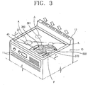
- Figure 3 is a perspective view showing a first embodiment of a structure of a gas radiation oven range and the cooking system in accordance with the present invention
- Figure 4 is an exploded perspective view showing a structure of the gas radiation oven range in accordance with the present invention
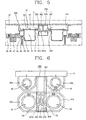
- Figure 5 is a partial longitudinal sectional view showing a structure of the gas radiation oven range in accordance with the present invention.
- the structure of the gas radiation oven range in accordance with the present invention includes an outer case 10 which is formed to have an internal space with the upper side opened, ceramic glass 20 which covers and is combined with the upper end of the outer case 10, for placing foodstuffs thereon, a first burner housing 300 which is combined and contacted with the lower surface of the ceramic glass 20, for forming an exhaust passage F with the lower surface of the ceramic glass 20 in a predetermined shape, a radiant burner 40 which is combined with a side surface of the first burner housing 300, for generating a radiant wave combusting mixed gas, and a shared discharge unit 360 which is positioned at the lower portion of the plurality of first burner housings 300, combined to be connected to the respective exhaust passage F and extended so that the exhaust gas, which is generated respectively from the plurality of radiant burners, is discharged to the exhaust duct 12 which is positioned at the rear side of the outer case 10.
- the outer case 10 is formed in a hexahedral shape with an upper side opened, an air inlet duct 11 to which air is flowed is formed on the front surface of the outer case 10, and an exhaust duct 12 is positioned on the rear surface of the hexahedron.
- the ceramic glass 20 is formed to have an area which can cover the upper end of the outer case 10 and a predetermined thickness and the ceramic glass 20 is formed with materials through which radiant wave generated from the radiant burner 40 can penetrate.
- a cooking area A is printed so that a cooked material can be positioned at a position where the radiant wave which is generated from the radiant burner penetrates.
- the first burner housing 300 includes a lower plate portion 310 in a rectangular shape which is formed to have a predetermined width and length, a side plate portion 320 which is formed bent and extended in the vertical direction corresponding to a contour of the lower plate portion 310 along the circumference on the side surface of the lower plate portion 310, a combining surface portion 330 formed extended and bent in parallel in the direction of the outer circumference from the end of the side plate portion 320 having a predetermined area, a plurality of mounting holes 340 which are penetrated and formed on both sides of the rectangular lower plate portion 310 so that the radiant burner 40 can be mounted and a plurality of exhaust through holes 350 which are formed corresponding to the mounting holes 340 in the center portion of the lower plate portion 310.
- the combining plate portion 330 As the combining plate portion 330 is contacted and combined to a lower surface of the ceramic glass 20, the combining plate portion 330 forms an exhaust passage F for discharging combustion gas and convection heat together with the first burner housing 300, lower plate portion 310, side plate portion 320 and a lower surface of the ceramic glass 20.
- Two or more mounting holes 340 are formed so that a large port having a predetermined diameter can be mounted.
- the plurality of exhaust through holes 350 can be formed to face each other at the center portion of the first burner housing 300 correspondingly, and can be formed in a row to each other at the side portion of the first burner housing 300.
- the shared exhaust duct 360 includes an exhaust stack 361 which is combined to be contacted on a side surface of the first burner housing and has a side surface in which a cut inflow hole 361 a is formed, so that exhaust gas, which is discharged from a plurality of exhaust through holes 350 which are formed on one side surface of the first burner housing 300, can be received, a partition 362 which is combined with the lower plate portion 310 of the first burner housing 300 in the direction of a normal line, and respectively divides exhaust gas which is generated from a plurality of radiant burner formed on both sides of the burner housing 300 by dividing an exhaust passage Fa of the burner housing 300a of a side and exhaust passage Fb of the burner housing 300b of the other side and an exhaust cover 363 whose upper side is positioned to be contacted on the lower substrate of the ceramic glass 20 and whose lower side is combined to the partition 362, for preventing convection heat of the exhaust gas which is generated in the radiant burner 40 from being transferred to the ceramic glass 20.
- the first burner housing 300 which is combined with the exhaust duct 360 is combined with a guide 370 which is bent corresponding to the shape and combined with the inner surface of the outer case 10.
- the radiant burner 40 is fixed and combined so that a burner head 41 where a mixing room M is formed can be positioned in the mounting hole 340 of the first burner housing 300 and a mixing gas tube 44 is combined to a side surface of the burner head 41.
- a burner mat 42 which is a radiator for radiating a radiant wave is fixed and combined to the upper side of the burner head 41 so that the burner mat 42 can cover the mixing room M of the burner head 41 by heating the mixed gas as the gas in the mixing room M is discharged and combusted.
- a ignition and inflammation detecting unit 43 for igniting the mixed gas which is outflowed through the burner mat 42 and detecting the combusting state of the gas, is combined to the lower plate portion 310 of the first burner housing 300 near from the burner mat 42.
- gas supplying tube 48 and air supplying tube 49 are branched and connected, and a nozzle 60 is combined to an inner side of a position where the gas supplying tube 48 and air supplying tube 49 cross.
- a fan housing 45 in which a blast fan 46 and fan motor 47 are mounted is combined to a rear end portion of the air supplying tube 49.
- the gas radiation oven range can be composed of a plurality of assemblies which are combined with the first burner housing 300 and radiant burner 40 according to the usage and size.
- the first embodiment of the gas radiation oven range in accordance with the present invention includes an outer case 10 which is formed to have an internal space with the upper side opened, ceramic glass 20 which is covered and combined with the upper end of the outer case 10, for placing foodstuffs therein, a first burner housing 300 which is combined and contacted with a lower surface of the ceramic glass 20, forms an exhaust passage F with the lower surface of the ceramic glass 20, and is integrally combined with a plurality of large ports in a dual structure, a second burner housing 400 in which respective medium port is formed at a side independently from the first burner housing 300 in which the plurality of large ports are formed, and third burner housing 500 in which a small port is formed, a radiant burner 40 which is combined with a side surface of the respective burner housings 300, 400 and 500, for generating a radiant wave, combusting mixed gas and a shared discharge unit 360 which is positioned among large ports which are integrally formed in the respective first burner housings 300, combined to be connected to the respective exhaust passage F which are formed at the
- the first burner housing 300 can be positioned at the front side of the product in which the inlet duct 11 of the outer case 10 is formed. Also, the second burner housing 400 and third burner housing 500 can be installed at the rear side of the product in which the exhaust duct 12 of the outer case 10 is formed, and vise versa.
- the shared discharge unit 360 includes an exhaust stack 361 which is combined to be contacted on a side surface of the first burner housing 300 and has a side surface in which a cut inflow hole 361 a is formed, so that exhaust gas, which is discharged from a plurality of exhaust through holes 350 which are formed on one side surface of the first burner housing 300, can be received,-a partition 362 which is combined with the lower plate portion 310 of the first burner housing 300 in the direction of a normal line, and respectively divides exhaust gas which is generated from a plurality of radiant burners formed on both sides of the first burner housing 300 by dividing an exhaust passage Fa of the burner housing 300a of a side and exhaust passage Fb of the burner housing 300b of the other side and an exhaust cover 363 whose upper side is positioned to be contacted on the lower substrate of the ceramic glass 20 and whose lower side is combined to the partition 362, for preventing convection heat of the exhaust gas which is generated in the radiant burner 40 from being transferred to the ceramic glass 20.
- the exhaust stack 361 which is combined with the lower portion of the first burner housing 300 is extended and formed to the lower portion between the second burner housing 400 and third burner housing 500 and connected to the exhaust duct 12 which is formed at the rear surface of the outer case 10.
- exhaust ducts (not shown) which are respectively formed on the side surfaces of the second and third burner housings 400 and 500, are directly connected to the exhaust duct 12 which is formed on the rear surface of the outer case 10.
- the plurality of exhaust through holes 350 which are formed corresponding to the mounting hole, are formed facing each other at the center portion of the first burner housing 300.
- the second embodiment of the cooking system of the gas radiation oven range in accordance with the present invention includes an outer case 10 which is formed with an upper side opened, having an internal space, a ceramic glass 20 which is covered and combined with an upper end of the outer case 10 and in which cooked material is positioned, a first burner housing 300 which is combined and contacted with a lower surface of the ceramic glass 20, forms an exhaust passage F with the lower surface of the ceramic glass 20, and is integrally combined with a plurality of large ports in a dual structure, a fourth burner housing 600 in which a plurality of medium ports and small ports which are independent from the first burner housing 300 which is integrally formed with the plurality of large ports, a radiant burner 40 which is combined with a side surface of the respective burner housings 300 and 600, for generating a radiant wave, combusting mixed gas and a shared discharge unit 460 which is positioned among the plurality of burner housings 300 and 600 and combined to be connected to respective exhaust passages F which are formed at a side portion of the burner housings 300
- the first burner housing 300 can be positioned at the front side of the product in which the inlet duct 11 of the outer case 10 is formed.
- the fourth burner housing 600 can be installed at the rear side of the product in which the exhaust duct 12 of the outer case 10 is formed, and vise versa.
- the shared discharge unit 460 includes an exhaust stack 461 which is combined to be contacted on a side surface of the first burner housing 300 and fourth burner housing 600 and has a side surface in which cut inflow holes 461 a are formed, so that exhaust gas, which is discharged from a plurality of exhaust through holes 350 and 650 which are formed on one side surface of the first burner housing 300 and fourth burner housing 600, can be received, partitions 362 and 462 which are combined with the lower plate portions 310 and 610 of the first burner housing 300 and fourth burner housing 600 in the direction of a normal line, and respectively divides exhaust gas which is generated from a plurality of radiant burners 40 formed on both sides of the burner housing 300 and fourth burner housing 600 by dividing an exhaust passage Fa of the burner housings 300a and 600a of a side and exhaust passage Fb of the burner housings 300b and 600b of the other side, and exhaust cover 363 and 463 whose upper side is positioned to be contacted on the lower substrate of the ceramic glass 20 and whose lower side is combined to the
- An exhaust stack 461 is combined with the lower portion of the first burner housing 300 and fourth burner housing 600 and shares the exhaust passage of the combustion gas and convection heat.
- a plurality of inflow grooves 461 a and 461 b are formed at the portion where the first burner housing 300 and fourth burner housing 600 are combined.
- the exhaust stack 461 is connected to the exhaust duct 12 which is formed on the rear surface of the outer case 11.
- the plurality of exhaust through holes 350 and 650 which are formed corresponding to the mounting holes 340 and 640, are formed to face each other at the center portions of the respective burner housings 300 and 600.
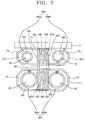
- the third embodiment of the cooking system of the gas radiation oven range in accordance with the present invention includes an outer case 10 which is formed with an upper side opened, having an internal space, a ceramic glass 20 which is covered and combined with an upper end of the outer case 10 and in which cooked material is positioned, a fifth burner housing 700 which is combined and contacted with a lower surface of the ceramic glass 20, forms an exhaust passage F with the lower surface of the ceramic glass 20, and is integrally combined with one or more large ports and one or more medium ports in a dual structure, a sixth burner housing 800 in which one or more large ports and one or more small ports which are positioned at the side portion independently from the fifth burner housing 700, are integrally formed, a radiant burner 40 which is combined with a side surface of the fifth burner housing 700 and sixth burner housing 800 respectively, for generating a radiant wave, combusting mixed gas and a shared discharge unit 560 which is positioned among the plurality of burner housings 700 and 800, and combined to be connected to respective exhaust passages Fa and Fb which are formed
- the fifth burner housing 700 - can be positioned at the right side to the front side of the product in which an inlet duct 11 of the outer case 10 is formed.
- the sixth burner housing 800 can be installed at the left side to the front side of the product in which the exhaust duct 12 of the outer case 10 is formed and vice versa.
- the shared discharge unit 560 includes an exhaust stack 561 which is combined to be contacted on side surfaces of the fifth burner housing 700 and sixth burner housing 800 and has a side surface in which cut inflow holes 561 a and 561 b are formed, so that exhaust gas, which is discharged from a plurality of exhaust through holes 750 and 850 which are formed on one side surface of the fifth burner housing 700 and sixth burner housing 800, can be received, a partition wall 562 which is combined to the inner portion of the exhaust stack 561, and respectively divides exhaust gas which is generated from a plurality of radiant burners 40 formed on both sides of the fifth burner housing 700 and sixth burner housing 800 by dividing exhaust passages Fa and Fb of the fifth burner housing 700 and exhaust passages Fa and Fb of the sixth burner housing 800, and first and second exhaust covers 563 and 564 which are combined with a center portion of the fifth burner housing 700 and sixth burner housing 800 with upper sides which are positioned to be contacted on the lower substrate of the ceramic glass 20, for dividing the exhaust passages Fa and Fb of the
- An exhaust stack 561 is combined to a lower portion of the fifth burner housing 700 and sixth burner housing 800 and shares exhaust passages of combustion gas and convection heat.
- a partition wall 562 for dividing the passage is combined being extended from the upper portion to lower portion of the inner side surface.
- a plurality of inflow grooves 561 a and 561 b are formed in a portion where the fifth burner housing 700 is combined with the sixth burner housing 800.
- the exhaust stack 561 is connected to the exhaust duct 12 which is formed on a rear surface of the outer case 11.
- the plurality of exhaust through holes 750 and 850 which are formed corresponding to the mounting holes 740 and 840, are formed in a side portion of the respective burner housings 700 and 800 in parallel.
- the mixed gas is discharged through the burner mat 42 and combusted simultaneously, and the burner mat 42 radiates radiant wave by heating the burner mat 42.
- the radiant wave which is radiated in the burner mat 42 penetrates the ceramic glass 20 and heats the cooking vessel (not shown) to cook the foodstuffs.
- the combustion gas and convection heat which are generated as the mixing gas is combusted, flow along through the exhaust passage F which is formed by the ceramic glass 20 and burner housings 300, 600, 700 and 800 at a predetermined flowrate and discharged to the outside of the gas radiation oven range through the exhaust duct 12 which is formed on the rear surface of the outer case 10 floating inside the exhaust stacks 361, 461 and 561 by passing the inflow grooves 361 a, 461 a, 461 b, 561 a and 561 b which are formed on a side surface of the exhaust passages 350, 650, 750 and 850 and exhaust stacks 361, 461 and 561 which are formed at the center portion of the lower plate portions 310, 610, 710 and 810 of the burner housing
- combustion gas and convection heat which are generated from the respective burner housings are separated by the partitions 362 and 462 and partition wall 562 so that they are not mixed.
- the gas radiation oven range can efficiently process the exhaust gas and prevent leakage of the gas by sharing the exhaust passage and having the corresponding structure of the burner housing.
- the apparatus of present invention is connected with a burner housing which is composed of an exhaust stack and two or more ports and accordingly the number of the component parts can be decreased and the assembling operation can become simpler.
- the present invention can satisfy property of the foodstuffs and demands of cooking industries for simultaneously cooking various foods.
Landscapes
- Engineering & Computer Science (AREA)
- Chemical & Material Sciences (AREA)
- Combustion & Propulsion (AREA)
- Mechanical Engineering (AREA)
- General Engineering & Computer Science (AREA)
- Gas Burners (AREA)
- Combustion Of Fluid Fuel (AREA)
Claims (27)
- Strahlungsgasherd, enthaltend:ein äußeres Gehäuse (10), dessen obere Seite offen ist und das so ausgebildet ist, dass es einen vorbestimmten Innenraum hat;ein Keramikglas (20), das das obere Ende des äußeren Gehäuses (10) abdeckt und mit diesem kombiniert ist und auf dem Kochgut positioniert wird;ein erstes Brennergehäuse (300), das mit der unteren Oberfläche des Keramikglases (20) in Kontakt ist und zusammen mit der unteren Oberfläche des Keramikglases (20) einen Abgaskanal (F, Fa, Fb) bildet;eine Vielzahl von Strahlungsbrennern (40), die mit einer Seitenfläche des ersten Brennergehäuses (300) kombiniert sind, zur Erzeugung einer Strahlungswelle und zur Verbrennung von Mischgas, wobei jeder Strahlungsbrenner (40) mit jeweils einem Abgaskanal (Fa, Fb) in einem Seitenabschnitt des ersten Brennergehäuses (300) verbunden ist; undeine gemeinsame Abzugseinheit (360), die zwischen der Vielzahl von Strahlungsbrennern (40) angeordnet ist und die von den Abgaskanälen (F, Fa, Fb) zu der hinteren Oberfläche des äußeren Gehäuses (10) verläuft, wo die gemeinsame Abzugseinheit (360) mit einer Abgasleitung (12) verbunden ist, die an der Rückseite des äußeren Gehäuses (10) angeordnet ist, um das jeweils von der Vielzahl von Strahlungsbrennern (40) erzeugte Abgas abzuleiten.
- Herd nach Anspruch 1, bei welchem das Brennergehäuse (300) umfasst:einen unteren Plattenabschnitt (310) in rechteckiger Form, der so ausgebildet ist, dass er eine vorbestimmte Breite und Länge hat;einen Seitenplattenabschnitt (320), der einem Umriss des unteren Plattenabschnitts (310) entsprechend entlang dem Umfang an der Seitenfläche des unteren Plattenabschnitts (310) in vertikaler Richtung umgebogen und fortgeführt gebildet ist;einen Verbindungsflächenabschnitt (330), der von dem Ende des Seitenplattenabschnitts (320) fortgeführt und parallel in Richtung des äußeren Umfangs umgebogen gebildet ist und eine vorbestimmte Fläche hat;eine Vielzahl von Montagelöchern (340), die an beiden Seiten des rechteckigen unteren Plattenabschnitts (310) durchgebohrt und so gebildet sind, dass der Strahlungsbrenner (40) montiert werden kann; undeine Vielzahl von Abgas-Durchgangslöchern (350), die den Montagelöchern (340) entsprechend in dem Mittelabschnitt des unteren Plattenabschnitts (310) gebildet sind.
- Herd nach Anspruch 2, bei welchem die Vielzahl von Abgas-Durchgangslöchern (350) korrespondierend gebildet ist, so dass sie im Mittelabschnitt des Brennergehäuses (300) einander gegenüberliegen.
- Herd nach Anspruch 2, bei welchem die Vielzahl von Abgas-Durchgangslöchern (350) parallel in einer Reihe in dem Seitenabschnitt des Brennergehäuses (300) gebildet ist.
- Herd nach Anspruch 1, bei welchem die gemeinsame Abzugseinheit (360) umfasst:einen Abgaskamin (361), der so verbunden ist, dass er an einer Seitenfläche des Brennergehäuses (300) in Kontakt gebracht wird und eine Seitenfläche hat, in der eine geschnittene Einströmöffnung (361a) gebildet ist, so dass Abgas, das von einer Vielzahl von Abgas-Durchgangslöchern (350) ausgestoßen wird, die an einer Seitenfläche des Brennergehäuses (300) gebildet sind, aufgenommen werden kann;eine Trennwand (362), die mit dem unteren Plattenabschnitt (310) des Brennergehäuses (300) in der Richtung einer Normallinie verbunden ist und jeweils Abgas, das von einer Vielzahl von Strahlungsbrennern (40) erzeugt wird, die auf beiden Seiten des Brennergehäuses (300a) gebildet sind, unterteilt, indem ein Abgaskanal (Fa) des Brennergehäuses (300a) an einer Seite und ein Abgaskanal (Fb) des Brennergehäuses (300b) an der anderen Seite abgeteilt werden; undeine Abgasabdeckung (363), deren Oberseite so positioniert ist, dass sie mit dem unteren Substrat des Keramikglases (20) in Kontakt gebracht wird und dessen Unterseite mit der Trennwand verbunden ist, um zu verhindern, dass Konvektionswärme des Abgases, das in dem Strahlungsbrenner (40) erzeugt wird, auf das Keramikglas (20) übertragen wird.
- Herd nach einem der Ansprüche 1 bis 5, bei welchem die Strahlungsbrenner (40) des ersten Brennergehäuses (300) große Öffnungen haben, die einstückig mit dem ersten Brennergehäuse (300) gebildet sind, und bei welchem ein zweites Brennergehäuse (400) mit jeweiligen mittleren Öffnungen an einer Seite unabhängig von dem ersten Brennergehäuse (300) und ein drittes Brennergehäuse (500) mit einer kleinen Öffnung vorgesehen sind.
- Herd nach Anspruch 6, bei welchem das erste Brennergehäuse (300), das einstückig mit der Vielzahl von großen Öffnungen verbunden ist, an der Vorderfläche des Produkts positioniert ist, in der eine Einlaßleitung (11) des äußeren Gehäuses (10) gebildet ist, und das zweite Brennergehäuse (400), in dem die mittlere Öffnung gebildet ist, und das dritte Brennergehäuse (500), in dem die kleine Öffnung gebildet ist, an der rückwärtigen Fläche des Produkts positioniert sind, an der die Abgasleitung (12) des äußeren Gehäuses (10) gebildet ist.
- Herd nach Anspruch 6, bei welchem das erste Brennergehäuse (300), das einstückig mit der Vielzahl von großen Öffnungen verbunden ist, an der rückwärtigen Fläche des Produkts positioniert ist, in der eine Abgasleitung (12) des äußeren Gehäuses (10) gebildet ist, und das zweite Brennergehäuse (400), in dem die mittlere Öffnung gebildet ist, und das dritte Brennergehäuse (500), in dem die kleine Öffnung gebildet ist, an der Vorderfläche des Produkts positioniert sind, an welcher die Einlaßleitung (11) des äußeren Gehäuses (10) gebildet ist.
- Herd nach Anspruch 6, bei welchem die Abgasleitungen des zweiten Brennergehäuses (400) und des dritten Brennergehäuses (500) direkt mit einer Abgasleitung (12) verbunden sind, die an der rückwärtigen Fläche des äußeren Gehäuses (10) gebildet ist.
- Herd nach Anspruch 6, bei welchem der Abgaskamin (361), der mit dem unteren Abschnitt des ersten Brennergehäuses (300) verbunden ist, an dem unteren Abschnitt zwischen dem zweiten und dem dritten Brennergehäuse (400, 500) verlängert gebildet ist und mit der Abgasleitung (12) verbunden ist, die an dem rückwärtigen Abschnitt des äußeren Gehäuses (10) gebildet ist.
- Herd nach Anspruch 6, bei welchem die Vielzahl von Abgas-Durchgangslöchern (350), die den jeweiligen Montagelöchern (340) entsprechend gebildet sind, korrespondierend so gebildet ist, dass sie einander in dem Mittelabschnitt des ersten Brennergehäuses (300) in der Mitte des unteren Plattenabschnitts (310) des ersten Brennergehäuses (300) gegenüberliegen.
- Herd nach einem der Ansprüche 1 bis 5, bei welchem die Brenner (40) des ersten Brennergehäuses (300) große Öffnungen haben, die einstückig mit dem ersten Brennergehäuse (300) gebildet sind, bei welchem ein zweites Brennergehäuse (600) vorgesehen ist, das mit einer Vielzahl von mittleren Öffnungen und kleinen Öffnungen einstückig gebildet ist, die von dem ersten Brennergehäuse (300) unabhängig sind, und bei welchem die gemeinsame Abzugseinheit (460) zwischen der Vielzahl von Brennergehäusen (300, 600) positioniert ist.
- Herd nach Anspruch 12, bei welchem das erste Brennergehäuse (300), das mit der Vielzahl von großen Öffnungen einstückig verbunden ist, an der Vorderfläche des Produkts positioniert ist, in der eine Einlaßleitung (11) des äußeren Gehäuses (10) gebildet ist, und das zweite Brennergehäuse (600), in welchem die mittlere Öffnung und kleine Öffnungen einstückig gebildet sind, an der rückwärtigen Fläche des Produkts positioniert ist, in der eine Abgasleitung (12) des äußeren Gehäuses (10) gebildet ist.
- Herd nach Anspruch 12, bei welchem das erste Brennergehäuse (300), das mit der Vielzahl von großen Öffnungen einstückig verbunden ist, an der rückwärtigen Fläche des Produkts positioniert ist, in der eine Abgasleitung (12) des äußeren Gehäuses (10) gebildet ist, und das zweite Brennergehäuse (600), in welchem die mittlere Öffnung und kleine Öffnungen einstückig gebildet sind, an der Vorderfläche des Produkts positioniert ist, in der eine Einlaßleitung (11) des äußeren Gehäuses (10) gebildet ist.
- Herd nach Anspruch 12, bei welchem das erste Brennergehäuse (300) und das zweite Brennergehäuse (600) einen Abgaskamin (461) für den Ausstoß von Abgas, das innerhalb des Gehäuses erzeugt wird, gemeinsam nutzen.
- Herd nach Anspruch 15, bei welchem eine Vielzahl von Einströmnuten (461a, 461b) an einer Seitenfläche des Abgaskamins (461) gebildet ist.
- Herd nach Anspruch 15, bei welchem der gemeinsame Abgaskamin (461) mit der Abgasleitung (12) verbunden ist, die an der rückwärtigen Fläche des äußeren Gehäuses (10) gebildet ist.
- Herd nach Anspruch 12, bei welchem die Vielzahl von Abgas-Durchgangslöchern (350, 650), die den jeweiligen Montagelöchern (340, 640) entsprechend gebildet sind, korrespondierend so gebildet sind, dass sie einander in dem Mittelabschnitt jedes Brennergehäuses (300, 600) in der Mitte des unteren Plattenabschnitts (310, 610) jedes Brennergehäuses (300, 600) gegenüberliegen.
- Herd nach Anspruch 1 bis 5, bei welchem die Strahlungsbrenner (40) des ersten Brennergehäuses (700) eine oder mehrere große Öffnungen und eine oder mehrere mittlere Öffnungen haben, welches erste Brennergehäuse (700) einstückig mit den Öffnungen verbunden ist, bei welchem ein zweites Brennergehäuse (800) vorgesehen ist, das einstückig mit einer oder mehreren großen Öffnungen und einer oder mehreren kleinen Öffnungen gebildet ist, die an dem Seitenabschnitt unabhängig von dem ersten Brennergehäuse (700) positioniert sind, und bei welchem die gemeinsame Abzugseinheit (560) zwischen dem ersten und dem zweiten Brennergehäuse (700, 800) positioniert ist.
- Herd nach Anspruch 19, bei welchem das erste Brennergehäuse (700), das mit einer oder mehreren großen Öffnungen und einer oder mehreren mittleren Öffnungen einstückig verbunden ist, an der rechten Seite zu der Vorderfläche des Produkts positioniert ist, in welcher die Einlaßleitung (11) des äußeren Gehäuses (10) gebildet ist, und das zweite Brennergehäuse (800), in welchem eine oder mehrere große Öffnungen und eine oder mehrere kleine Öffnungen einstückig gebildet sind, an der linken Seite zu der Vorderfläche des Produkts positioniert ist, in der die Einlaßleitung (11) des äußeren Gehäuses (10) gebildet ist.
- Herd nach Anspruch 19, bei welchem das erste Brennergehäuse (700), das mit einer oder mehreren großen Öffnungen und einer oder mehreren mittleren Öffnungen einstückig verbunden ist, an der linken Seite zu der Vorderfläche des Produkts positioniert ist, in welcher die Einlaßleitung (11) des äußeren Gehäuses (10) gebildet ist, und das zweite Brennergehäuse (800), in welchem eine oder mehrere große Öffnungen und eine oder mehrere kleine Öffnungen einstückig gebildet sind, an der rechten Seite zu der Vorderfläche des Produkts positioniert ist, in der die Einlaßleitung (11) des äußeren Gehäuses (10) gebildet ist.
- Herd nach Anspruch 19, bei welchem das erste Brennergehäuse (700) und das zweite Brennergehäuse (800) einen Abgaskamin (561) für den Ausstoß von Abgas gemeinsam nutzen, das innerhalb des Gehäuses erzeugt wird.
- Herd nach Anspruch 19, bei welchem eine Vielzahl von Einströmnuten (561a, 561b) an einer Seitenfläche des Abgaskamins (561) gebildet ist.
- Herd nach Anspruch 19, bei welchem der Abgaskamin (561) zur gemeinsamen Nutzung mit der Abgasleitung (12) verbunden ist, die an der rückwärtigen Fläche des äußeren Gehäuses (10) gebildet ist.
- Herd nach Anspruch 19, bei welchem die Vielzahl von Abgas-Durchgangslöchern (750, 850), die den jeweiligen Montagelöchern (740, 840) entsprechend an dem Seitenabschnitt des unteren Plattenabschnitts (710, 810) der jeweiligen Brennergehäuse (700, 800) gebildet sind, in dem Seitenabschnitt der jeweiligen Brennergehäuse (700, 800) in einer Reihe gebildet sind.
- Herd nach Anspruch 19, bei welchem der Kanal, der an dem inneren Mittelabschnitt des Abgaskamins (561) gebildet ist, unterteilt ist, indem eine Trennwand (562), die so verbunden ist, dass sie sich von dem oberen Abschnitt zu dem unteren Abschnitt der inneren Oberfläche des Abgaskamins (561) erstreckt, angeordnet ist.
- Herd nach einem der Ansprüche 1 bis 5, bei welchem eine Vielzahl von Brennergehäusen (300, ..., 800) vorgesehen sind, die so verbunden sind, dass sie mit einer unteren Oberfläche des Keramikglases (20) in Kontakt stehen, so dass sie einen Abgaskanal (F, Fa, Fb) mit der unteren Oberfläche des Keramikglases (20) bilden, wobei die Vielzahl der Brennergehäuse (300, ..., 800) mit der Vielzahl von Öffnungen mit verschiedenen Größen einstückig verbunden ist und wobei die gemeinsam genutzte Abzugseinheit (360) zwischen der Vielzahl der Brennergehäuse (300, ..., 800) positioniert ist.
Applications Claiming Priority (1)
| Application Number | Priority Date | Filing Date | Title |
|---|---|---|---|
| PCT/KR2002/002245 WO2004051145A1 (en) | 2002-11-29 | 2002-11-29 | Gas radiation oven range |
Publications (2)
| Publication Number | Publication Date |
|---|---|
| EP1573251A1 EP1573251A1 (de) | 2005-09-14 |
| EP1573251B1 true EP1573251B1 (de) | 2007-01-17 |
Family
ID=32464301
Family Applications (1)
| Application Number | Title | Priority Date | Filing Date |
|---|---|---|---|
| EP02790999A Revoked EP1573251B1 (de) | 2002-11-29 | 2002-11-29 | Gasherd |
Country Status (6)
| Country | Link |
|---|---|
| US (1) | US7690374B2 (de) |
| EP (1) | EP1573251B1 (de) |
| CN (1) | CN100374779C (de) |
| AU (1) | AU2002368420A1 (de) |
| DE (1) | DE60217737T2 (de) |
| WO (1) | WO2004051145A1 (de) |
Cited By (1)
| Publication number | Priority date | Publication date | Assignee | Title |
|---|---|---|---|---|
| US7856972B2 (en) | 2002-12-12 | 2010-12-28 | Lg Electronics Inc. | Apparatus for ventilation in a radiation gas range |
Families Citing this family (13)
| Publication number | Priority date | Publication date | Assignee | Title |
|---|---|---|---|---|
| US7481210B2 (en) * | 2004-10-12 | 2009-01-27 | Lg Electronics Inc. | Gas range |
| US7942143B2 (en) * | 2006-12-20 | 2011-05-17 | Lg Electronics Inc. | Heating cooking appliance and burner system thereof |
| KR100936155B1 (ko) * | 2007-12-05 | 2010-01-12 | 엘지전자 주식회사 | 노즐어셈블리 및 이를 포함하는 조리기기 |
| US20090301462A1 (en) * | 2008-06-04 | 2009-12-10 | Churchill Steve P | Cover for stovetop mounted in counter |
| US8757138B2 (en) * | 2010-08-30 | 2014-06-24 | General Electric Company | Gas cooktop apparatus |
| USD696893S1 (en) * | 2011-10-28 | 2014-01-07 | Electrolux Home Products Corporation N.V. | Induction cooker |
| USD704978S1 (en) * | 2012-11-29 | 2014-05-20 | Samsung Electronics Co., Ltd. | Oven |
| ITTO20121158A1 (it) * | 2012-12-27 | 2014-06-28 | Indesit Co Spa | Apparecchio di cottura con bruciatore a gas di potenza termica elevata e metodo per il suo funzionamento |
| KR101573989B1 (ko) * | 2013-12-26 | 2015-12-02 | 엘지전자 주식회사 | 조리기기 및 버너 유닛 |
| KR101617499B1 (ko) | 2013-12-26 | 2016-05-02 | 엘지전자 주식회사 | 조리기기 및 버너 유닛 |
| US20160298859A1 (en) * | 2015-04-07 | 2016-10-13 | Green Heat Corporation | Heat reclamation apparatus and method |
| CN106500135B (zh) * | 2015-09-03 | 2020-01-14 | Lg电子株式会社 | 燃气烹饪设备 |
| WO2021143788A1 (zh) * | 2020-01-16 | 2021-07-22 | 佛山罗丹合众电器科技有限公司 | 一种带有排油烟功能的灶具 |
Family Cites Families (49)
| Publication number | Priority date | Publication date | Assignee | Title |
|---|---|---|---|---|
| US3468298A (en) * | 1967-01-23 | 1969-09-23 | Columbia Gas Syst | Gas stove |
| US3494350A (en) * | 1968-05-03 | 1970-02-10 | Tappan Co The | Smooth top gas range with regenerator |
| US3698378A (en) * | 1968-07-12 | 1972-10-17 | Inst Gas Technology | Smooth top gas range |
| US3586825A (en) * | 1968-10-03 | 1971-06-22 | Modern Maid Inc | Flush top cooking unit with ventilating means |
| US3555995A (en) * | 1969-02-20 | 1971-01-19 | Victor M Berger | Electric grill |
| US3663798A (en) * | 1969-08-25 | 1972-05-16 | Thermo Electron Corp | An infrared heating surface |
| US3596650A (en) * | 1970-01-15 | 1971-08-03 | Jenn Air Corp | Ventilated cooking range |
| US3633562A (en) * | 1970-03-30 | 1972-01-11 | Columbia Gas Service Corp | Slightly pressurized flat-top stove |
| US3797375A (en) * | 1972-03-16 | 1974-03-19 | Jenn Air Corp | Stove with selectively interchangeable cooking apparatus |
| US3785364A (en) * | 1972-06-05 | 1974-01-15 | Columbia Gas Syst Service Corp | Smooth top range |
| US4020821A (en) * | 1975-03-10 | 1977-05-03 | Columbia Gas System Service Corporation | Gas-fired smooth top range |
| YU109677A (en) * | 1976-05-15 | 1982-05-31 | Spezialglas Gmbh | Glass ceramic surface for cooking by means of the radiating gas-heated surface |
| DE2641274C3 (de) * | 1976-09-14 | 1979-08-23 | Jenaer Glaswerk Schott & Gen., 6500 Mainz | Sicherheitseinrichtung für gasbeheizte, transparente Glaskeramikkochflächen |
| FI61562C (fi) * | 1979-12-14 | 1982-08-10 | Jorma Wallasvaara | Spis |
| US4431892A (en) * | 1981-07-17 | 1984-02-14 | Jenn-Air Corporation | Ventilated modular cooktop cartridge |
| JPS58178988A (ja) * | 1982-04-14 | 1983-10-20 | 松下電器産業株式会社 | 調理器ユニツト |
| EP0124022B1 (de) * | 1983-04-30 | 1989-06-07 | Schott Glaswerke | Kochfeld mit gasbeheizten Brennstellen und einer durchgehenden Kochfläche aus Glaskeramik oder vergleichbarem Material |
| US4549052A (en) * | 1984-01-12 | 1985-10-22 | The Maytag Company | Cooling system for an induction cooking cartridge |
| US5400765A (en) * | 1986-05-16 | 1995-03-28 | Quantum Group, Inc. | Selective emissive cooking stove |
| US4724823A (en) * | 1986-09-29 | 1988-02-16 | Solaronics, Inc. | Radiant gas burner assembly |
| US4962694A (en) * | 1988-04-15 | 1990-10-16 | Graver James H | Grill exhaust system |
| DE3844081A1 (de) * | 1988-12-28 | 1990-07-05 | Cramer Gmbh & Co Kg | Kochapparat mit zumindest einem kochfeld |
| ES2018440A6 (es) * | 1989-12-11 | 1991-04-01 | Catalana Gas Sa | Perfeccionamientos en encimeras a gas. |
| FR2678360B1 (fr) * | 1991-06-28 | 1993-09-10 | Applic Gaz Sa | Appareil de chauffage avec bruleur catalytique. |
| US5119802A (en) * | 1991-09-09 | 1992-06-09 | Cherry David N | Gas cooktop appliance for use with downdraft ventilation system |
| US5246365A (en) * | 1992-03-13 | 1993-09-21 | Maytag Corporation | Reignition device for a gas burner |
| US5209217A (en) * | 1992-07-24 | 1993-05-11 | Maytag Corporation | Downdraft gas range with dual mode burner system |
| US5406932A (en) * | 1992-10-23 | 1995-04-18 | Canadian Gas Research Institute | Sealed combustion range |
| US5568804A (en) * | 1992-10-23 | 1996-10-29 | Canadian Gas Research Institute | Sealed combustion range |
| US5301653A (en) * | 1993-01-25 | 1994-04-12 | Caloric Corporation | Gas range having down draft with automatic shutoff during ignition |
| IT1268515B1 (it) * | 1993-04-02 | 1997-03-04 | Zanussi Grandi Impianti Spa | Piano di cottura a gas ad irraggiamento |
| DE4326945C2 (de) * | 1993-08-11 | 1996-10-24 | Schott Glaswerke | Regeleinrichtung für die Gaszufuhr zu einer Gaskocheinrichtung mit unter einer durchgehenden Kochfläche angeordneten Gasstrahlungsbrennern |
| FR2731065B1 (fr) * | 1995-02-27 | 2001-07-27 | Toyotomi Kogyo Co Ltd | Dispositif de cuisson |
| US5619982A (en) * | 1995-07-31 | 1997-04-15 | Maytag Corporation | Method and apparatus for operating a downdraft cooking vapor withdrawal system |
| DE19545842C1 (de) * | 1995-12-08 | 1996-10-10 | Schott Glaswerke | Modular aufgebaute Kochfeldanordnung unter einer Glaskeramik-Kochfläche |
| DE19637666A1 (de) * | 1996-09-16 | 1998-03-26 | Schott Glaswerke | Druckregeleinrichtung für die Gaszufuhr zu einer Gaskocheinrichtung mit unter einer durchgehenden Kochfläche angeordneten Gasstrahlungsbrennern |
| DE19703301C2 (de) * | 1997-01-30 | 2000-06-08 | Schott Glas | Gaskochgerät |
| CN2428707Y (zh) * | 1999-12-09 | 2001-05-02 | 王晓东 | 烟道式燃气灶 |
| US6349714B1 (en) * | 2000-03-09 | 2002-02-26 | Gas Research Institute | Cooking range and control assembly and burner therefor |
| US6293276B1 (en) * | 2000-07-31 | 2001-09-25 | Andrea Gonzella Owens | Cook grill top lid |
| KR20020056337A (ko) * | 2000-12-29 | 2002-07-10 | 구자홍 | 가스복사 조리기의 내부 케이스 구조 |
| JP2002206713A (ja) * | 2001-01-10 | 2002-07-26 | Tokyo Gas Co Ltd | 平坦加熱面型ガスコンロ |
| ITMI20010247U1 (it) * | 2001-05-03 | 2002-11-04 | Whirlpool Co | Bruciatore atmosferico a gas di tipo radiante |
| US6807962B2 (en) * | 2002-01-28 | 2004-10-26 | Schott Glas | Kitchen gas cooking stove with a glass-ceramic, glass, or ceramic top, a gas cooktop with a glass-ceramic, glass, or ceramic top, and a glass-ceramic, glass, or ceramic top of a cooking stove or cooktop with a venting structure thereon |
| CN100402932C (zh) * | 2002-11-29 | 2008-07-16 | Lg电子株式会社 | 气体辐射炉灶 |
| EP1585922B1 (de) * | 2002-12-12 | 2014-11-19 | LG Electronics, Inc. | Vorrichtung zur entlüftung eines strahlungsgasherds |
| US6830045B2 (en) * | 2003-03-12 | 2004-12-14 | Maytag Corporation | Gas burner module for a cooking appliance |
| US6966315B2 (en) * | 2003-06-26 | 2005-11-22 | Maytag Corporation | Smooth surface gas cooktop having an electric ignition/turndown system |
| JP4114622B2 (ja) * | 2004-03-16 | 2008-07-09 | 松下電器産業株式会社 | 組み込み式加熱調理器 |
-
2002
- 2002-11-29 EP EP02790999A patent/EP1573251B1/de not_active Revoked
- 2002-11-29 CN CNB028301625A patent/CN100374779C/zh not_active Expired - Fee Related
- 2002-11-29 WO PCT/KR2002/002245 patent/WO2004051145A1/en not_active Ceased
- 2002-11-29 AU AU2002368420A patent/AU2002368420A1/en not_active Abandoned
- 2002-11-29 DE DE60217737T patent/DE60217737T2/de not_active Revoked
- 2002-11-29 US US10/536,395 patent/US7690374B2/en not_active Expired - Lifetime
Cited By (1)
| Publication number | Priority date | Publication date | Assignee | Title |
|---|---|---|---|---|
| US7856972B2 (en) | 2002-12-12 | 2010-12-28 | Lg Electronics Inc. | Apparatus for ventilation in a radiation gas range |
Also Published As
| Publication number | Publication date |
|---|---|
| CN1720415A (zh) | 2006-01-11 |
| EP1573251A1 (de) | 2005-09-14 |
| DE60217737D1 (de) | 2007-03-08 |
| US20060048767A1 (en) | 2006-03-09 |
| AU2002368420A1 (en) | 2004-06-23 |
| DE60217737T2 (de) | 2007-11-15 |
| US7690374B2 (en) | 2010-04-06 |
| CN100374779C (zh) | 2008-03-12 |
| WO2004051145A1 (en) | 2004-06-17 |
Similar Documents
| Publication | Publication Date | Title |
|---|---|---|
| US7690374B2 (en) | Gas radiation oven range | |
| US7856973B2 (en) | Cooking appliance | |
| US4430541A (en) | Combination microwave gas convection oven | |
| US5655511A (en) | Gas fired convection oven | |
| EP1573250B1 (de) | Montagestruktur für verbrennungsgebläse eines gasherdes | |
| US10539331B2 (en) | Cooking appliance | |
| US20220282871A1 (en) | Oven bake heating channel exchange system | |
| EP3489587B1 (de) | Kochvorrichtung | |
| CN100402933C (zh) | 辐射燃气灶的排气装置 | |
| AU2005202035B2 (en) | Gas Range | |
| KR100741799B1 (ko) | 가스 복사 조리기 | |
| KR101864493B1 (ko) | 조리기기 및 그 제어방법 | |
| KR101220624B1 (ko) | 가스레인지용 그릴 상부버너 | |
| JP2011080710A (ja) | 加熱装置 | |
| US11988379B2 (en) | Burner for a cooking appliance | |
| KR200309891Y1 (ko) | 가스 오븐레인지의 컨벡션구조 | |
| KR20250083818A (ko) | 조리기기 및 조리기기의 제어방법 | |
| WO2003040626A1 (en) | Convection oven with gas burner | |
| KR200349518Y1 (ko) | 전기오븐의 챔버커버 구조 | |
| CN122072086A (en) | Cooking device | |
| JP2006162202A (ja) | ガスコンロ | |
| KR20250083820A (ko) | 조리기기 | |
| KR101274725B1 (ko) | 가스레인지 | |
| KR20020056223A (ko) | 가스복사 조리기의 연소가스 누설방지구조 | |
| KR20020056414A (ko) | 가스복사 조리기의 예열구조 |
Legal Events
| Date | Code | Title | Description |
|---|---|---|---|
| PUAI | Public reference made under article 153(3) epc to a published international application that has entered the european phase |
Free format text: ORIGINAL CODE: 0009012 |
|
| 17P | Request for examination filed |
Effective date: 20050617 |
|
| AK | Designated contracting states |
Kind code of ref document: A1 Designated state(s): AT BE BG CH CY CZ DE DK EE ES FI FR GB GR IE IT LI LU MC NL PT SE SK TR |
|
| AX | Request for extension of the european patent |
Extension state: AL LT LV MK RO SI |
|
| DAX | Request for extension of the european patent (deleted) | ||
| RBV | Designated contracting states (corrected) |
Designated state(s): DE IT |
|
| GRAP | Despatch of communication of intention to grant a patent |
Free format text: ORIGINAL CODE: EPIDOSNIGR1 |
|
| RIN1 | Information on inventor provided before grant (corrected) |
Inventor name: CHOUNG, SUG-MOON Inventor name: LEE, DAE-RAESEOKBONGMAEUL BUYEONG APT.802-1604. Inventor name: KIM, YANG-HO Inventor name: KIM, IN-GYU Inventor name: JUNG, DAE-HEE; |
|
| GRAS | Grant fee paid |
Free format text: ORIGINAL CODE: EPIDOSNIGR3 |
|
| GRAA | (expected) grant |
Free format text: ORIGINAL CODE: 0009210 |
|
| AK | Designated contracting states |
Kind code of ref document: B1 Designated state(s): DE IT |
|
| RAP1 | Party data changed (applicant data changed or rights of an application transferred) |
Owner name: LG ELECTRONICS INC. |
|
| REF | Corresponds to: |
Ref document number: 60217737 Country of ref document: DE Date of ref document: 20070308 Kind code of ref document: P |
|
| RAP4 | Party data changed (patent owner data changed or rights of a patent transferred) |
Owner name: LG ELECTRONICS INC. |
|
| PLBI | Opposition filed |
Free format text: ORIGINAL CODE: 0009260 |
|
| PLAX | Notice of opposition and request to file observation + time limit sent |
Free format text: ORIGINAL CODE: EPIDOSNOBS2 |
|
| 26 | Opposition filed |
Opponent name: AEG HAUSGERAETE GMBH Effective date: 20071015 |
|
| PLAF | Information modified related to communication of a notice of opposition and request to file observations + time limit |
Free format text: ORIGINAL CODE: EPIDOSCOBS2 |
|
| RDAF | Communication despatched that patent is revoked |
Free format text: ORIGINAL CODE: EPIDOSNREV1 |
|
| PGFP | Annual fee paid to national office [announced via postgrant information from national office to epo] |
Ref country code: DE Payment date: 20081127 Year of fee payment: 7 |
|
| RDAG | Patent revoked |
Free format text: ORIGINAL CODE: 0009271 |
|
| STAA | Information on the status of an ep patent application or granted ep patent |
Free format text: STATUS: PATENT REVOKED |
|
| 27W | Patent revoked |
Effective date: 20081201 |
|
| PG25 | Lapsed in a contracting state [announced via postgrant information from national office to epo] |
Ref country code: IT Free format text: LAPSE BECAUSE OF NON-PAYMENT OF DUE FEES Effective date: 20071130 |