EP1573241B1 - Entlüfter - Google Patents
Entlüfter Download PDFInfo
- Publication number
- EP1573241B1 EP1573241B1 EP03813871A EP03813871A EP1573241B1 EP 1573241 B1 EP1573241 B1 EP 1573241B1 EP 03813871 A EP03813871 A EP 03813871A EP 03813871 A EP03813871 A EP 03813871A EP 1573241 B1 EP1573241 B1 EP 1573241B1
- Authority
- EP
- European Patent Office
- Prior art keywords
- float
- air
- heating system
- valve
- protective element
- Prior art date
- Legal status (The legal status is an assumption and is not a legal conclusion. Google has not performed a legal analysis and makes no representation as to the accuracy of the status listed.)
- Expired - Lifetime
Links
- 230000000740 bleeding effect Effects 0.000 title abstract 4
- 230000001681 protective effect Effects 0.000 claims abstract description 54
- 238000010438 heat treatment Methods 0.000 claims abstract description 32
- 239000007788 liquid Substances 0.000 claims abstract description 21
- 239000002245 particle Substances 0.000 claims abstract description 6
- 238000007789 sealing Methods 0.000 claims description 12
- 239000004743 Polypropylene Substances 0.000 claims description 4
- 229920001155 polypropylene Polymers 0.000 claims description 4
- XLYOFNOQVPJJNP-UHFFFAOYSA-N water Substances O XLYOFNOQVPJJNP-UHFFFAOYSA-N 0.000 claims description 4
- 230000008878 coupling Effects 0.000 claims description 3
- 238000010168 coupling process Methods 0.000 claims description 3
- 238000005859 coupling reaction Methods 0.000 claims description 3
- 239000004033 plastic Substances 0.000 claims description 2
- 229920003023 plastic Polymers 0.000 claims description 2
- -1 polypropylene Polymers 0.000 claims description 2
- RZVAJINKPMORJF-UHFFFAOYSA-N Acetaminophen Chemical compound CC(=O)NC1=CC=C(O)C=C1 RZVAJINKPMORJF-UHFFFAOYSA-N 0.000 abstract 1
- 239000013529 heat transfer fluid Substances 0.000 description 23
- 238000013022 venting Methods 0.000 description 11
- 238000013459 approach Methods 0.000 description 5
- 238000011109 contamination Methods 0.000 description 3
- 238000013461 design Methods 0.000 description 3
- 230000007774 longterm Effects 0.000 description 2
- UCKMPCXJQFINFW-UHFFFAOYSA-N Sulphide Chemical compound [S-2] UCKMPCXJQFINFW-UHFFFAOYSA-N 0.000 description 1
- 230000005587 bubbling Effects 0.000 description 1
- 238000005352 clarification Methods 0.000 description 1
- 238000004140 cleaning Methods 0.000 description 1
- 230000006835 compression Effects 0.000 description 1
- 238000007906 compression Methods 0.000 description 1
- 230000006378 damage Effects 0.000 description 1
- 238000009434 installation Methods 0.000 description 1
- 230000005923 long-lasting effect Effects 0.000 description 1
- 238000012423 maintenance Methods 0.000 description 1
- 238000004519 manufacturing process Methods 0.000 description 1
- 230000002093 peripheral effect Effects 0.000 description 1
- 229920006389 polyphenyl polymer Polymers 0.000 description 1
- 239000010802 sludge Substances 0.000 description 1
- 239000007921 spray Substances 0.000 description 1
- 238000009423 ventilation Methods 0.000 description 1
Images

Classifications
-
- F—MECHANICAL ENGINEERING; LIGHTING; HEATING; WEAPONS; BLASTING
- F16—ENGINEERING ELEMENTS AND UNITS; GENERAL MEASURES FOR PRODUCING AND MAINTAINING EFFECTIVE FUNCTIONING OF MACHINES OR INSTALLATIONS; THERMAL INSULATION IN GENERAL
- F16K—VALVES; TAPS; COCKS; ACTUATING-FLOATS; DEVICES FOR VENTING OR AERATING
- F16K24/00—Devices, e.g. valves, for venting or aerating enclosures
- F16K24/04—Devices, e.g. valves, for venting or aerating enclosures for venting only
- F16K24/042—Devices, e.g. valves, for venting or aerating enclosures for venting only actuated by a float
- F16K24/048—Devices, e.g. valves, for venting or aerating enclosures for venting only actuated by a float a transmission element, e.g. arm, being interposed between the float and the valve element, the transmission element following a non-translational, e.g. pivoting or rocking, movement when actuated
-
- F—MECHANICAL ENGINEERING; LIGHTING; HEATING; WEAPONS; BLASTING
- F24—HEATING; RANGES; VENTILATING
- F24D—DOMESTIC- OR SPACE-HEATING SYSTEMS, e.g. CENTRAL HEATING SYSTEMS; DOMESTIC HOT-WATER SUPPLY SYSTEMS; ELEMENTS OR COMPONENTS THEREFOR
- F24D19/00—Details
- F24D19/08—Arrangements for drainage, venting or aerating
- F24D19/082—Arrangements for drainage, venting or aerating for water heating systems
- F24D19/083—Venting arrangements
- F24D19/085—Arrangement of venting valves for central heating radiators
- F24D19/087—Arrangement of venting valves for central heating radiators automatic
Definitions
- the invention relates to a heating system with a heat transfer fluid and with a quick exhaust having a breather housing having a connection for connection to the heating system and in which a float and an air compensation valve is provided, which coupled above the float with this via an actuating mechanism which actuating mechanism comprises a lifting lever fixed to the float, which has at its upper end a coupling connection for a pivoting lever, wherein a protective element is arranged between the float and the air compensation valve.
- Heating systems are already known which have such a rapid exhaust fan in order to dissipate the air contained in the heating system into the external environment during the operation of heating systems occurring thermally induced changes in the filling volume. Even when filling such systems Quick exhaust fan to the air in the heating system to the outside.
- a float arranged in the quick-ventilator opens a valve whenever the liquid level has fallen below a certain level due to the accumulating air there.
- the air compensation valve is contaminated or destroyed in the course of operation, when the air balance valve or its actuating mechanism comes into contact with the heat transfer fluid, since in the heat transfer fluid often dirt particles are carried.
- the additional valve should therefore ensure only a slight cleaning or repair of the air balance valve and remains inoperative during the intended opening and closing movements of the air compensation valve.
- the prior art valve known from EP 0 133 992 therefore can not seal the air compensation valve arranged sufficiently above the liquid in the housing extension against the heat transfer fluid present in the previously known quick exhaust valve.
- venting device for a pipeline system is known, in which flows a contaminated with dirt and foreign matter liquid.
- the previously known venting device is specially for sewers and for sludge removal in the field of agriculture, forestry and fisheries.
- the previously known venting device has a valve arrangement arranged in series with the atmosphere and consisting of a plurality of valves, which valve arrangement is arranged above a conically widening clarification tank.
- valve assembly is arranged in a valve housing, which is separated from the clarifier by two conical and a labyrinth-forming plates-The Klär actuallyer facing valves of this valve assembly are connected via a wire linkage with a float located in the clarifier in functional connection, at a lower liquid level in the clarifier Valves and thus the air supply opens.
- a conical splash guard is held, which closes the peripheral edge of the overlying conical plates at an upper liquid level
- Venting device is not a generic quick exhaust fan, which is intended for connection to a heating system.
- the previously known venting device does not flow through a liquid serving as a heat carrier.
- the spray guard serving as a protective element of the previously known venting device should not seal any of the venting valves provided in the valve arrangement against the liquid in the venting device, because otherwise the comparatively complex valve arrangement will comprise several valves connected in series in JP-A-06 042661 previously known venting would be completely superfluous.
- the invention proposes that at the other end of the pivot lever belonging to the air balance valve and spring-loaded in the closed position of the air compensation valve valve plate is arranged, which cooperates with a valve seat of the air compensation valve, that the protective element for shielding the air compensation valve at least compared to contained in the liquid Dirt particles in the stroke direction of the float is movable, and that the protective element rests with the air compensation valve closed at an upper sealing stop and thereby seals the air compensation valve against existing in the quick exhaust heat transfer fluid.
- the provided between the air balance valve and float actuator mechanism is long-lasting and durable without maintenance, because between the interacting parts only low frictional forces are effective and the structure is simple.
- a simple opening and closing of the air compensation valve is favored by the movement of the float.
- provided protective element can effectively protect the air compensation valve even in small and compact quick-release without large space requirement against contamination. Since the protective element is movable in the stroke direction of the float and with the air compensation valve closed, seals it against the heat transfer fluid present in the quick exhaust, the protective element can move with the changing level of the heat transfer fluid and as the heat transfer fluid rises above a certain level Protect the air compensation valve by applying it to the sealing stop in front of the heat transfer fluid.
- the air accumulating in the breather housing can flow past the protective element to the air compensation valve
- openings for the passage of air are present when the air compensation valve is open and the protective element is spaced apart from the sealing stop in the edge region of the protective element or the adjacent inner wall of the breather housing. Since the level of the heat transfer fluid is relatively low at a too large amount of air in the breather housing, thereby also the protective element can be arranged lower. At the same time, the air can flow past the protective element and the sealing stop.
- a preferably circumferential annular gap is provided with a radial width of about half a millimeter.
- Such an annular gap can be easily realized and at the same time the friction between the protective element and the inner wall of the Lower breather housing sharply.
- the protective element in the breather housing is very easy to move.
- An expedient embodiment of the rapid exhaust fan may be that in the breather housing in the lower, the connection for the heat transfer fluid having part of the float is guided, that the breather above the float has a receiving area for the protective element and that in particular above the sealing stop for the protective element the air compensation valve and at least a part of its actuating mechanism is arranged.
- the air present in the heating system can easily penetrate from below into the quick exhaust and flow over the surface of the heat transfer fluid, past the protective element and the sealing stop up and then escape through the air compensation valve.
- the heat transfer fluid present in the heating system and the connected quick exhaust is water.
- Water has a relatively high heat capacity and at the same time is an often and readily available and inexpensive liquid.
- An easily manufactured and flexibly usable embodiment of the protective element may be when the protective element is a flat disc.
- the float has a different cross-sectional shape than the breather in the stroke range of the float and is preferably hexagonal. As a result, the air can easily escape from the Escape surface of the heat transfer fluid, since not the entire liquid surface is taken by the float.
- the protective screen is easily and directly movable together with the float
- the protective disk with the float preferably in one piece is connected and when the protective disk and the float are spaced from each other. Due to the spacing of the float and the protective pane, a distance between the protective pane and the liquid surface can thus be created, which can keep possible splashes away from the protective pane and thus further increase the protection of the parts to be protected behind it.
- the protective disk and the float made of plastic, preferably polypropylene (PP) and / or polyphenyl sulfide (PPS) exists.
- PP polypropylene
- PPS polyphenyl sulfide
- the longitudinal axis of the quick exhaust in mounting position is approximately vertical, when the float is guided vertically in the interior of the quick exhaust when the connection for the heating system at the lower end of the quick exhaust and when the air balance valve is located at the top of the quick exhaust.
- the air can easily rise from bottom to top through the breather housing and escape through the air compensation valve.
- the air compensation valve is arranged transversely to the longitudinal axis of the quick exhaust.
- the air can escape well from an air compensation valve arranged in this way, but the overall length of the quick-acting ventilator drops and thus the usability increases, above all, in narrow places of heating systems.
- a compact design for installation can be very important.
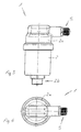
- a designated as a whole with 1 and particularly well in section in Figures 1 and 2 recognizable quick exhaust fan for heating systems with a heat transfer fluid has a breather housing 2 with a connection 2b for connection to the heating system.
- a breather housing 2 In the breather housing 2 is a float 3 and one above the float 3 via an actuating mechanism 4 arranged with the float 3 air compensation valve 5 is arranged.
- a protective element 6 is arranged for shielding the air compensation valve 5 against dirt particles contained in the liquid.
- the protective element 6 When open air compensation valve 5, as shown in Figure 1, the protective element 6 is spaced from the sealing stopper 7. In this case, in addition to the protective element 6 or in its edge region, air can flow past the protective element 6.
- the protective element 6 as a flow-through opening between its outer edge and the adjacent inner wall of the breather housing 2 to a circumferential annular gap, which has a radial width of about half a millimeter.
- the float 3 is guided in the lower part of the breather housing 2, which also has a connection 2b for the heat transfer fluid.
- the float 3 in this case has a different cross-sectional shape, for example a hexagonal shape, as the breather housing 2 in the stroke region of the float 3.
- Above the float 3 has the Breather 2 on a receiving area for the protective element 6.
- the actuating mechanism 4 of the air compensation valve 5 is arranged partially above and partially below the protective element 6 designed as a flat disk.
- the actuating mechanism 4 a lifting lever 4a, which is fixed to the float 3 and on the axial extent of the protective element 6 is arranged.
- the protective element 6 is axially spaced from the float 3 and the protective element 6 is connected in one piece to the lifting lever 4 a and this in turn to the float 3.
- this has a coupling connection 4 b formed as a receptacle for a pivot lever 4 c engaging therein, at the other end of which a valve plate 4 d belonging to the air compensation valve 5 is arranged.
- This valve plate 4d cooperates with an inner valve opening or the valve seat 5a of the air compensation valve 5 pointing into the breather housing 2.
- the valve plate 4d is spring-loaded on its underside in the closing direction of the air compensation valve 5 by a compression spring 8.
- FIGS. 1 and 2 show the rapid exhaust fan 1 in its mounting position, in which the longitudinal axis of the quick exhaust fan 1 extends vertically.
- the float 3 as is clear in FIGS. 1 and 2, is also guided vertically.
- the connection 2b for the heat transfer fluid or for the heating system is arranged at the lower end of the quick exhaust 1 and the air compensation valve at the upper end of the quick exhaust 1.
- the air compensation valve 5 is mounted laterally on the breather housing 2 and transversely to the longitudinal axis of the quick breather 1.
Landscapes
- Engineering & Computer Science (AREA)
- General Engineering & Computer Science (AREA)
- Mechanical Engineering (AREA)
- Combustion & Propulsion (AREA)
- Thermal Sciences (AREA)
- Chemical & Material Sciences (AREA)
- Physics & Mathematics (AREA)
- Self-Closing Valves And Venting Or Aerating Valves (AREA)
- Central Heating Systems (AREA)
- Duct Arrangements (AREA)
- Materials For Medical Uses (AREA)
- Absorbent Articles And Supports Therefor (AREA)
- Magnetic Resonance Imaging Apparatus (AREA)
Description
- Die Erfindung betrifft ein Heizungssystem mit einer Wärmeträger-Flüssigkeit sowie mit einem Schnellentlüfter, der ein Entlüftergehäuse aufweist, das einen Anschluß zum Verbinden mit dem Heizungssystem hat und in dem ein Schwimmer sowie ein Luftausgleichsventil vorgesehen ist, das oberhalb des Schwimmers mit diesem über einen Betätigungsmechanismus gekoppelt ist, welcher Betätigungsmechanismus einen am Schwimmer befestigten Hubhebel aufweist, der an seinem oberen Ende eine Kupplungsverbindung für einen Schwenkhebel hat, wobei zwischen dem Schwimmer und dem Luftausgleichsventil ein Schutzelement angeordnet ist.
- Man kennt bereits Heizungssysteme, die einen derartigen Schnellentlüfter aufweisen, um während des Betriebs von Heizungssystemen auftretenden thermisch bedingten Änderungen des Füllvolumens die in dem Heizungssystem enthaltene Luft in die äußere Umgebung abzuführen. Auch beim Befüllen solcher Systeme dienen Schnellentlüfter zur Abgabe der Luft im Heizungssystem nach außen. Dabei öffnet ein im Schnellentlüfter angeordneter Schwimmer ein Ventil immer dann, wenn das Flüssigkeitsniveau durch die sich dort ansammelnde Luft unter ein bestimmtes Niveau gesunken ist. Dabei wird das Luftausgleichsventil im Laufe des Betriebs verunreinigt oder zerstört, wenn das Luftausgleichsventil beziehungsweise sein Betätigungsmechanismus mit der Wärmeträger-Flüssigkeit in Berührung kommt, da in der Wärmeträger-Flüssigkeit oftmals Schmutzpartikel mitgeführt werden. Bisher wurde dies dadurch vermieden, dass ein genügend großer Abstand zwischen Luftausgleichsventil und dem Niveau der Wärmeträger-Flüssigkeit vorhanden ist, der insbesondere auch vor Spritzern, zum Beispiel durch Blasenbildung in der Wärmeträger-Flüssigkeit, schützt. Ein solcher Schnellentlüfter ist beispielsweise in DE 32 07 321 C3 beschrieben. Mit einem solchen großen Abstand zwischen Luftausgleichsventil und dem Niveau der Wärmeträger-Flüssigkeit wächst jedoch auch die Baugröße des Schnellentlüfters.
- Aus der EP 0 133 992 ist bereits ein Schnellentlüfter für Heizungssysteme bekannt, der an der Oberseite seines Entlüftergehäuses einen nach oben ragenden Gehäuseansatz trägt. Um das Luftausgleichsventil des vorbekannten Schnellentlüfters gegen eine Verschmutzung zu schützen, ist das Luftausgleichsventil im Gehäuseansatz lediglich hinreichend oberhalb der Flüssigkeit angeordnet. Im Bereich der auf das Luftausgleichsventil einwirkenden und im Gehäuseinneren zwischen dem Entlüftergehäuse sowie dem Gehäuseansatz angeordneten Betätigungsmittel ist ein weiteres Zusatwentil vorgesehen, das jedoch nur die Funktion eines Hilfsventils hat. Das Zusatzventil schließt beim Öffnen des Gehäuseansatzes sowie des darin befindlichen Luftausgleichsventils unter dem Einfluß einer auf das Zusatzventil einwirkenden Federbelastung den Gehäuseansatz. Das Zusatzventil soll daher nur eine leichte Reinigung oder Reparatur des Luftausgleichsventils sicherstellen und bleibt während der bestimmungsgemäßen Öffen- und Schließbewegungen des Luftausgleichsventils funktionslos. Das aus EP 0 133 992 vorbekannte Zusatzventil vermag daher das im Gehäuseansatz hinreichend oberhalb der Flüssigkeit angeordnete Luftausgleichsventil nicht gegen die im vorbekannten Schnellentlüfter vorhandene wärmeträger-Flüssigkeit abzudichten.
- Aus der JP-A-06 042661 ist eine Entlüftungseinrichtung für ein Rohrleitungssystem bekannt, in welchem eine mit Schmutz- und Fremdstoffen belastete Flüssigkeit fließt. Die vorbekannte Entlüftungseinrichtung ist speziell für Abwasserleitungen sowie zur Schlammabfuhr im Bereich der Land- und Forstwirtschaft sowie der Fischerei bestimmt. Die vorbekannte Entlüftungseinrichtung weist eine zur Atmosphäre hin in Reihe geschaltete und aus mehreren Ventilen bestehende Ventilanordnung auf, die oberhalb eines sich konisch erweiternden Klärbehälters angeordnet ist. Die Ventilanordnung ist in einem Ventilgehäuse angeordnet, das vom Klärbehältnis durch zwei konische und ein Labyrinth bildende Platten abgetrennt ist-Die dem Klärbehälter zugewandten Ventile dieser Ventilanordnung stehen über ein Drahtgestänge mit einem im Klärbehälter befindlichen Schwimmkörper in Funktionsverbindung, der bei einem unteren Flüssigkeitspegel im Klärbehälter die Ventile und damit die Luftzufuhr öffnet. An dem Drahtgestänge ist ein konischer Spritzschutz gehalten, der bei einem oberen Flüssigkeitspegel den Umfangsrand der darüber liegenden konischen Platten verschließt,
- Bei der aus JP-A-06 042661 vorbekannten Entlüftungseinrichtung handelt es sich jedoch nicht um einen gattungsgemäßen Schnellentlüfter, der zum Anschluß an ein Heizungssystem bestimmt ist. Ebenso wenig wird die vorbekannte Entlüftungseinrichtung von einer als Wärmeträger dienenden Flüssigkeit durchströmt. Vor allem aber soll der als Schutzelement dienende Spritzschutz der vorbekannten Entlüftungseinrichtung keines der in der Ventilanordnung vorgesehenen Entlüftungsventile gegen die in der Entlüftungseinrichtung befindliche Flüssigkeit abdichten, weil andernfalls die vergleichsweise komplexe ventilanordnung mit mehreren, in Reihe geschalteten Ventilen bei der aus JP-A-06 042661 vorbekannten Entlüftungseinrichtung völlig überflüssig wäre.
- Aus der JP D2 300 577 A ist eine mit JP-A-06 042661 vergleichbare Entlüftungseinrichtung vorbekannt, bei der zwischen dem Klärbehälter und dem Entlüftungsventil ein Sieb vorgesehen ist. Das Sieb vermag zwar die zum Entlüftungsventil mit aufschwimmenden Schmutzpartikel zu reduzieren, kann jedoch keinesfalls das Entlüftungsventil vollständig gegen die in der vorbekannten Entlüftungseinrichtung vorhandene Flüssigkeit abdichten.
- Es besteht daher die Aufgabe, einen Schnellentlüfter zu schaffen, der eine kleine und kompakte Bauform hat und bei dem das Luftausgleichsventil langzeitig vor Verschmutzung beziehungsweise vor Zerstörung geschützt ist.
- Zur Lösung dieser Aufgabe wird erfindungsgemäß vorgeschlagen, dass am anderen Ende des Schwenkhebels eine zum Luftausgleichsventil gehörende und in Schließstellung des Luftausgleichsventils federbeaufschlagte ventilplatte angeordnet ist, die mit einem Ventilsitz des Luftausgleichsventils zusammenwirkt, dass das Schutzelement zum Abschirmen des Luftausgleichsventils zumindest gegenüber von in der Flüssigkeit enthaltenen Schmutzpartikeln in Hubrichtung des Schwimmers bewegbar ist, und dass das Schutzelement bei geschlossenem Luftausgleichsventil an einem oberen Dichtanschlag anliegt und dabei das Luftausgleichsventil gegen die in dem Schnellentlüfter vorhandene Wärmeträger-Flüssigkeit abdichtet.
- Der zwischen Luftausgleichsventil und Schwimmer vorgesehene Betätigungsmechanismus ist langzeitig und ohne Wartung haltbar, weil zwischen den zusammenwirkenden Teilen nur geringe Reibungskräfte wirksam sind und der Aufbau einfach ist. Dabei wird ein einfaches Öffnen und Schließen des Luftausgleichsventils durch die Bewegung des Schwimmers begünstigt. Das bei dem vorliegenden Erfindungsgegenstand vorgesehene Schutzelement kann das Luftausgleichsventil auch in kleinen und kompakten Schnellentlüftern ohne großen Platzbedarf wirksam gegen Verschmutzung schützen. Da das Schutzelement in Hubrichtung des Schwimmers bewegbar ist und bei geschlossenem Luftausgleichsventil dieses gegen die in dem Schnellentlüfter vorhandene Wärmeträger-Flüssigkeit abdichtet, kann sich das Schutzelement mit dem sich verändernden Niveau der Wärmeträger-Flüssigkeit bewegen und beim Ansteigen der Wärmeträger-Flüssigkeit über ein bestimmtes Niveau das Luftausgleichsventil durch das Anlegen an den Dichtanschlag vor der Wärmeträger-Flüssigkeit schützen.
- Damit die sich im Entlüftergehäuse ansammelnde Luft an dem Schutzelement vorbei zum Luftausgleichsventil strömen kann, ist es zweckmäßig, wenn bei geöffnetem Luftausgleichsventil sowie bei zum Dichtanschlag beabstandeten Schutzelement im Randbereich des Schutzelements oder der benachbarten inneren Wandung des Entlüftergehäuses Öffnungen zum Durchtritt von Luft vorhanden sind. Da das Niveau der Wärmeträger-Flüssigkeit bei einer zu großen Menge Luft in Entlüftergehäuse relativ niedrig ist, kann dadurch auch das Schutzelement niedriger angeordnet sein. Gleichzeitig kann die Luft an dem Schutzelement und dem Dichtanschlag vorbeiströmen.
- Vorteilhaft ist es dabei, wenn als Durchströmöffnung für die Luft zwischen dem äußeren Rand des Schutzelements und der inneren wandung des Entlüftergehäuses ein vorzugsweise umlaufender Ringspalt mit einer radialen Breite von etwa einem halben Millimeter vorgesehen ist. Ein solcher Ringspalt kann einfach realisierbar sein und kann gleichzeitig die Reibung zwischen Schutzelement und innerer Wandung des Entlüftergehäuses stark senken. Dadurch ist das Schutzelement in dem Entlüftergehäuse sehr leicht bewegbar.
- Eine zweckmäßige Ausführungsform des Schnellentlüfters kann darin bestehen, dass im Entlüftergehäuse im unteren, den Anschluss für die Wärmeträger-Flüssigkeit aufweisenden Teil der Schwimmer geführt ist, dass das Entlüftergehäuse oberhalb des Schwimmers einen Aufnahmebereich für das Schutzelement aufweist und dass insbesondere oberhalb des Dichtanschlags für das Schutzelement das Luftausgleichsventil und zumindest ein Teil von dessen Betätigungsmechanismus angeordnet ist. In einem so beschaffenen Schnellentlüfter kann die im Heizungssystem vorhandene Luft leicht von unten in den Schnellentlüfter eindringen und über die Oberfläche der Wärmeträger-Flüssigkeit, am Schutzelement und dem Dichtanschlag vorbei nach oben strömen und dann durch das Luftausgleichsventil entweichen.
- Zweckmäßig ist es, wenn die in dem Heizungssystem und dem angeschlossenen Schnellentlüfter vorhandene Wärmeträger-Flüssigkeit Wasser ist. Wasser hat eine relativ hohe wärmekapazität und ist gleichzeitig eine oft und leicht verfügbare und preiswerte Flüssigkeit.
- Eine einfach herzustellende und flexibel einsetzbare Ausführungsform des Schutzelements kann sein, wenn das Schutzelement eine flache Scheibe ist.
- Für eine leichtgängige und freie Bewegung des Schwimmers im Entlüftergehäuse ist es vorteilhaft, wenn der Schwimmer eine andere Querschnittsform aufweist als das Entlüftergehäuse im Hubbereich des Schwimmers und vorzugsweise sechseckig ausgebildet ist. Dadurch kann auch die Luft leicht aus der Oberfläche der Wärmeträger-Flüssigkeit entweichen, da nicht die gesamte Flüssigkeits-Oberfläche vom Schwimmer eingenommen wird.
- Damit die Schutzscheibe leicht und unmittelbar mit dem Schwimmer zusammen bewegbar ist, ist es zweckmäßig, wenn die Schutzscheibe mit dem Schwimmer vorzugsweise einstückig verbunden ist und wenn die Schutzscheibe und der Schwimmer voneinander beabstandet sind. Durch die Beabstandung des Schwimmers und der Schutzscheibe kann damit auch ein Abstand zwischen Schutzscheibe und Flüssigkeits-Oberfläche geschaffen werden, der eventuelle Spritzer von der Schutzscheibe fernhalten kann und damit den Schutz der dahinterliegenden zu schützenden Teile noch weiter vergrößern kann.
- Für eine kostengünstige Herstellung und gleichzeitig eine langzeitige Haltbarkeit des Schwimmers mit der damit verbundenen Schutzscheibe ist es vorteilhaft, wenn die Schutzscheibe und der Schwimmer aus Kunststoff, vorzugsweise aus Polypropylen (PP) und/oder Polyphenylsulfid (PPS), besteht.
- Für ein leichtes Entweichen der Luft aus der Wärmeträger-Flüssigkeit ist es zweckmäßig, wenn die Längsachse des Schnellentlüfters in Montagestellung etwa vertikal verläuft, wenn der Schwimmer im Inneren des Schnellentlüfters etwa vertikal geführt ist, wenn der Anschluss für das Heizungssystem am unteren Ende des Schnellentlüfters ist und wenn das Luftausgleichsventil am oberen Ende des Schnellentlüfters angeordnet ist. So kann die Luft leicht von unten nach oben durch das Entlüftergehäuse steigen und durch das Luftausgleichsventil entweichen.
- Um den Schnellentlüfter in seiner Bauform noch kleiner und kompakter gestalten zu können, ist es sehr vorteilhaft, wenn das Luftausgleichsventil quer zur Längsachse des Schnellentlüfters angeordnet ist. Die Luft kann aus einem so angeordneten Luftausgleichsventil gut entweichen, wobei jedoch die Gesamtlänge des Schnellentlüfters sinkt und damit die Einsetzbarkeit vor allem an engen Stellen von Heizungssystemen steigt. Vor allem beim Einbau des Schnellentlüfters in der Nähe des Heizkessels zum Entlüften des Heizungssystems an dieser Stelle, wo durch besonders große Temperaturunterschiede in der Wärmeträger-Flüssigkeit viel Luft frei wird und entweichen muss, kann eine kompakte Bauform für den Einbau sehr wichtig sein.
- Nachstehend sind Ausführungsbeispiele der Erfindung anhand der Zeichnung näher beschrieben. Es zeigt in zum Teil schematisierter Darstellung:
- Fig. 1
- einen Längsschnitt durch einen erfindungsgemäßen Schnellentlüfter mit einem geöffneten Luftausgleichsventil,
- Fig. 2
- einen Längsschnitt entsprechend Fig.1 mit geschlossenem Luftausgleichsventil des Schnellentlüfters, wobei ein Schutzelement das Luftausgleichsventil durch Beaufschlagung eines Dichtanschlags zusätzlich schützt,
- Fig. 3
- eine Seitenansicht des erfindungsgemäßen Schnellentlüfters sowie
- Fig. 4
- eine Ansicht von oben des erfindungsgemäßen Schnellentlüfters.
- Ein im Ganzen mit 1 bezeichneter und besonders gut im Schnitt in den Fig.1 und 2 erkennbarer Schnellentlüfter für Heizungssysteme mit einer Wärmeträger-Flüssigkeit weist ein Entlüftergehäuse 2 mit einem Anschluss 2b zum Verbinden mit dem Heizungssystem auf. In dem Entlüftergehäuse 2 ist ein Schwimmer 3 sowie ein oberhalb des Schwimmers 3 über einen Betätigungsmechanismus 4 mit dem Schwimmer 3 gekoppeltes Luftausgleichsventil 5 angeordnet. Zwischen Schwimmer 3 und dem Luftausgleichsventil 5 ist ein Schutzelement 6 zum Abschirmen des Luftausgleichsventils 5 gegen von in der Flüssigkeit enthaltenen Schmutzpartikeln angeordnet.
- Die beiden in den Fig.1 und 2 gezeigten unterschiedlichen Betriebszustände des Schnellentlüfters 1 zeigen im Vergleich, dass das Schutzelement 6 in Hubrichtung des Schwimmers 3 bewegbar ist. Ist das Luftausgleichsventil 5 geschlossen, wie in Fig.2 dargestellt, liegt das Schutzelement 6 an einem oberen Dichtanschlag 7 an und dichtet das Luftausgleichsventil 5 sowie dessen Betätigungsmechanismus 4 gegen die im Schnellentlüfter 1 vorhandene Wärmeträger-Flüssigkeit, die im allgemeinen Wasser ist, ab.
- Bei geöffnetem Luftausgleichsventil 5, wie in Fig.1 dargestellt, ist das Schutzelement 6 zum Dichtanschlag 7 beabstandet. Dabei kann neben dem Schutzelement 6 beziehungsweise in seinem Randbereich Luft an dem Schutzelement 6 vorbeiströmen. Dazu weist das Schutzelement 6 als Durchströmöffnung zwischen seinem äußeren Rand und der benachbarten inneren Wandung des Entlüftergehäuses 2 einen umlaufenden Ringspalt auf, der eine radiale Breite von etwa einem halben Millimeter hat.
- In dem in den Fig.1 und 2 im Schnitt gezeigten Ausführungsbeispiel ist der Schwimmer 3 im unteren Teil des Entlüftergehäuses 2 geführt, welches auch einen Anschluss 2b für die Wärmeträger-Flüssigkeit aufweist. Der Schwimmer 3 weist dabei eine andere Querschnittsform, beispielsweise eine sechseckige Form, als das Entlüftergehäuse 2 im Hubbereich des Schwimmers 3 auf. Oberhalb des Schwimmers 3 weist das Entlüftergehäuse 2 einen Aufnahmebereich für das Schutzelement 6 auf. Der Betätigungsmechanismus 4 des Luftausgleichsventils 5 ist teilweise oberhalb und teilweise unterhalb des als flache Scheibe ausgebildeten Schutzelementes 6 angeordnet.
- Dabei weist der Betätigungsmechanismus 4 einen Hubhebel 4a auf, der am Schwimmer 3 befestigt ist und auf dessen axialer Erstreckung das Schutzelement 6 angeordnet ist. Dabei ist das Schutzelement 6 vom Schwimmer 3 axial beabstandet und das Schutzelement 6 ist mit dem Hubhebel 4a und dieser wiederum mit dem Schwimmer 3 einstückig verbunden. Am oberen Ende des Hubhebels 4a weist dieser eine als Aufnahme für einen darin eingreifenden Schwenkhebel 4c ausgebildete Kupplungsverbindung 4b auf, an dessen anderen Ende eine zum Luftausgleichsventil 5 gehörende Ventilplatte 4d angeordnet ist. Diese Ventilplatte 4d wirkt mit einer in das Entlüftergehäuse 2 weisenden, inneren Ventilöffnung beziehungsweise dem Ventilsitz 5a des Luftausgleichsventils 5 zusammen. Dabei ist die Ventilplatte 4d an ihrer Unterseite in Schließrichtung des Luftausgleichsventils 5 durch eine Druckfeder 8 federbeaufschlagt.
- Fig.3 zeigt den Schnellentlüfter 1 in seiner Montagestellung, in der die Längsachse des Schnellentlüfters 1 vertikal verläuft. Dadurch wird auch der Schwimmer 3, wie in Fig.1 und 2 deutlich wird, vertikal geführt. Der Anschluss 2b für die Wärmeträger-Flüssigkeit beziehungsweise für das Heizungssystem ist am unteren Ende des Schnellentlüfters 1 und das Luftausgleichsventil am oberen Ende des Schnellentlüfters 1 angeordnet. Dabei ist das Luftausgleichsventil 5 seitlich am Entlüftergehäuse 2 und quer zur Längsachse des Schnellentlüfters 1 angebracht.
Claims (11)
- Heizungssystem mit einer wärmeträger-Flüssigkeit sowie mit einem Schnellentlüfter (1), der ein Entlüftergehäuse (2) aufweist, das (2) einen Anschluß (2b) zum Verbinden mit dem Heizungssystem hat und in dem (2) ein Schwimmer (3) sowie ein Luftausgleichsventil (5) vorgesehen ist, das (5) oberhalb des Schwimmers (3) mit diesem über einen Betätigungsmechanismus (4) gekoppelt ist, welcher Betätigungsmechanismus (4) einen am Schwimmer (3) befestigten Hubhebel (4a) aufweist, der an seinem oberen Ende eine Kupplungsverbindung (4b) für einen Schwenkhebel (4c) hat, wobei zwischen dem Schwimmer (3) und dem Luftausgleichsventil (5) ein Schutzelement (6) angeordnet ist, dadurch gekennzeichnet, dass am anderen Ende des Schwenkhebels (4c) eine zum Luftausgleichsventil (5) gehörende und in Schließstellung des Luftausgleichsventils (5) federbeaufschlagte Ventilplatte (4d) angeordnet ist, die mit einem Ventilsitz (5a) des Luftausgleichsventils (5) zusammenwirkt, dass das Schutzelement (6) zum Abschirmen des Luftausgleichsventils (5) zumindest gegenüber von in der Flüssigkeit enthaltenen Schmutzpartikeln in Hubrichtung des Schwimmers (3) bewegbar ist, und dass das Schutzelement (6) bei geschlossenem Luftausgleichsventil (5) an einem oberen Dichtanschlag (7) anliegt und dabei das Luftausgleichsventil (5) gegen die in dem Schnellentlüfter (1) vorhandene Wärmeträger-Flüssigkeit abdichtet.
- Heizungssystem nach Anspruch 1, dadurch gekennzeichnet, dass bei geöffnetem Luftausgleichsventil (5) sowie bei zum Dichtanschlag (7) beabstandeten Schutzelement (6) im Randbereich des Schutzelements (6) oder der benachbarten inneren Wandung des Entlüftergehäuses (2) Öffnungen zum Durchtritt von Luft vorhanden sind.
- Heizungssystem nach einem der Ansprüche 1 oder 2, dadurch gekennzeichnet, dass als Durchströmöffnung für die Luft zwischen dem äußeren Rand des Schutzelements (6) und der inneren Wandung des Entlüftergehäuses (2) ein vorzugsweise umlaufender Ringspalt mit einer radialen Breite von etwa einem halben Millimeter vorgesehen ist.
- Heizungssystem nach einem der Ansprüche 1 bis 3, dadurch gekennzeichnet, dass im Entlüftergehäuse (2) im unteren, den Anschluss (2b) für die Wärmeträger-Flüssigkeit aufweisenden Teil der Schwimmer (3) geführt ist, dass das Entlüftergehäuse (2) oberhalb des Schwimmers (3) einen Aufnahmebereich für das Schutzelement (6) aufweist und dass insbesondere oberhalb des Dichtanschlags (7) für das Schutzelement (6) das Luftausgleichsventil (5) und zumindest ein Teil von dessen Betätigungsmechanismus (4) angeordnet ist.
- Heizungssystem nach einem der Ansprüche 1 bis 4, dadurch gekennzeichnet, dass die in dem Heizungssystem und dem angeschlossenen Schnellentlüfter (1) vorhandene Wärmeträger-Flüssigkeit Wasser ist.
- Heizungssystem nach einem der Ansprüche 1 bis 5, dadurch gekennzeichnet, dass das Schutzelement (6) eine flache Scheibe ist.
- Heizungssystem nach einem der Ansprüche 1 bis 6, dadurch gekennzeichnet, dass der Schwimmer (3) eine andere Querschnittsform aufweist als das Entlüftergehäuse (2) im Hubbereich des Schwimmers (3) und vorzugsweise sechseckig ausgebildet ist.
- Heizungssystem nach einem der Ansprüche 1 bis 7, dadurch gekennzeichnet, dass die Schutzscheibe (6) mit dem Schwimmer (3) vorzugsweise einstückig verbunden ist und dass die Schutzscheibe (6) und der Schwimmer (3) voneinander beabstandet sind.
- Heizungssystem nach einem der Ansprüche 1 bis 8, dadurch gekennzeichnet, dass die Schutzscheibe (6) und der Schwimmer (3) aus Kunststoff, vorzugsweise aus Polypropylen (PP) und/oder Polyphenylsulfid (PPS), besteht.
- Heizungssystem nach einem der Ansprüche 1 bis 9, dadurch gekennzeichnet, dass die Längsachse des Schnellentlüfters (1) in Montagestellung etwa vertikal verläuft, dass der Schwimmer (3) im Inneren des Schnellentlüfters (1) etwa vertikal geführt ist, dass der Anschluss (2b) für das Heizungssystem am unteren Ende des Schnellentlüfters (1) ist und dass das Luftausgleichsventil (5) am oberen Ende des Schnellentlüfters (1) angeordnet ist.
- Heizungssystem nach einem der Ansprüche 1 bis 10, dadurch gekennzeichnet, dass das Luftausgleichsventil (5) quer zur Längsachse des Schnellentlüfters (1) angeordnet ist.
Applications Claiming Priority (3)
| Application Number | Priority Date | Filing Date | Title |
|---|---|---|---|
| DE10261936A DE10261936B4 (de) | 2002-12-20 | 2002-12-20 | Schnellentlüfter |
| DE10261936 | 2002-12-20 | ||
| PCT/EP2003/007908 WO2004059199A1 (de) | 2002-12-20 | 2003-07-19 | Entlüfter |
Publications (2)
| Publication Number | Publication Date |
|---|---|
| EP1573241A1 EP1573241A1 (de) | 2005-09-14 |
| EP1573241B1 true EP1573241B1 (de) | 2006-06-07 |
Family
ID=32478142
Family Applications (1)
| Application Number | Title | Priority Date | Filing Date |
|---|---|---|---|
| EP03813871A Expired - Lifetime EP1573241B1 (de) | 2002-12-20 | 2003-07-19 | Entlüfter |
Country Status (5)
| Country | Link |
|---|---|
| EP (1) | EP1573241B1 (de) |
| AT (1) | ATE329187T1 (de) |
| AU (1) | AU2003257483A1 (de) |
| DE (2) | DE10261936B4 (de) |
| WO (1) | WO2004059199A1 (de) |
Cited By (2)
| Publication number | Priority date | Publication date | Assignee | Title |
|---|---|---|---|---|
| EP1927802A3 (de) * | 2006-11-30 | 2009-09-16 | Caleffi S.p.A. | Schwimmerartiges Entlüftungsventil |
| EP3879129A1 (de) * | 2020-01-24 | 2021-09-15 | RG Prototypenbau UG | Kunststoffschraube |
Families Citing this family (4)
| Publication number | Priority date | Publication date | Assignee | Title |
|---|---|---|---|---|
| DE102016009664A1 (de) | 2016-08-09 | 2018-02-15 | Daimler Ag | Kühleinrichtung für eine Verbrennungskraftmaschine, insbesondere eines Kraftfahrzeugs |
| IT201700029292A1 (it) * | 2017-03-16 | 2018-09-16 | Rbm Spa | Valvola ad azione automatica per lo sfiato dell’aria da un impianto idraulico di riscaldamento e/o raffrescamento, in particolare di tipo domestico e/o industriale, e relativi gruppo otturatore e metodo di realizzazione ed assemblaggio |
| DE102018116440A1 (de) * | 2018-07-06 | 2020-01-09 | Volkswagen Aktiengesellschaft | Kühlkreislauf für ein Kraftfahrzeug und Komponente des Kühlkreislaufs sowie ein Entlüftungsventil |
| WO2022101752A1 (en) * | 2020-11-13 | 2022-05-19 | Giacomini S.P.A. | Deaerator with integrated shut-off valve |
Family Cites Families (7)
| Publication number | Priority date | Publication date | Assignee | Title |
|---|---|---|---|---|
| DE7738268U1 (de) * | 1977-01-04 | 1978-05-11 | Flamco B.V., Gouda (Niederlande) | Selbsttätiger Entlüfter |
| DE3207321A1 (de) * | 1982-03-01 | 1983-09-08 | Gebr. Tuxhorn KG, 4800 Bielefeld | Vorrichtung zum entlueften von leitungssystemen mit geschlossenem wasserkreislauf |
| DE3327846A1 (de) * | 1983-08-02 | 1985-02-14 | Hans Sasserath & Co Kg, 4052 Korschenbroich | Entlueftungsventil |
| JP2619953B2 (ja) * | 1989-05-12 | 1997-06-11 | 株式会社クボタ | 空気弁 |
| JP3153969B2 (ja) * | 1992-07-24 | 2001-04-09 | 前澤工業株式会社 | 空気弁 |
| DE9412420U1 (de) * | 1994-08-02 | 1994-09-22 | Sikla GmbH, 78595 Hausen | Schnellentlüfter für Heizungssysteme |
| HUP0003785A3 (en) * | 1998-05-27 | 2002-05-28 | Ferrero Rubinetterie S N C Di | Automatic air-bleed valve for hydraulic systems |
-
2002
- 2002-12-20 DE DE10261936A patent/DE10261936B4/de not_active Expired - Fee Related
-
2003
- 2003-07-19 WO PCT/EP2003/007908 patent/WO2004059199A1/de not_active Ceased
- 2003-07-19 AU AU2003257483A patent/AU2003257483A1/en not_active Abandoned
- 2003-07-19 EP EP03813871A patent/EP1573241B1/de not_active Expired - Lifetime
- 2003-07-19 AT AT03813871T patent/ATE329187T1/de active
- 2003-07-19 DE DE50303750T patent/DE50303750D1/de not_active Expired - Lifetime
Cited By (2)
| Publication number | Priority date | Publication date | Assignee | Title |
|---|---|---|---|---|
| EP1927802A3 (de) * | 2006-11-30 | 2009-09-16 | Caleffi S.p.A. | Schwimmerartiges Entlüftungsventil |
| EP3879129A1 (de) * | 2020-01-24 | 2021-09-15 | RG Prototypenbau UG | Kunststoffschraube |
Also Published As
| Publication number | Publication date |
|---|---|
| DE10261936B4 (de) | 2007-09-13 |
| DE10261936A1 (de) | 2004-07-08 |
| AU2003257483A1 (en) | 2004-07-22 |
| WO2004059199A8 (de) | 2004-12-29 |
| EP1573241A1 (de) | 2005-09-14 |
| WO2004059199A1 (de) | 2004-07-15 |
| ATE329187T1 (de) | 2006-06-15 |
| DE50303750D1 (de) | 2006-07-20 |
Similar Documents
| Publication | Publication Date | Title |
|---|---|---|
| EP0300280B1 (de) | Elektromagnetventil, insbesondere Auslaufventil für Brühwasser | |
| EP2087213B1 (de) | Vorrichtung zum abscheiden von ölteilchen aus dem kurbelgehäuselüftungsgas einer brennkraftmaschine | |
| DE19651117C2 (de) | Gasentlüftungsvorrichtung für einen Kraftstofftank | |
| DE69017729T2 (de) | Selbstbelüftetes Entleerungsventil. | |
| DE69832042T2 (de) | Absperrfülventil | |
| DE102009035349A1 (de) | Steuervorrichtung für den Kühlmittelfluss im Kühlkreislauf einer Brennkraftmaschine | |
| DE19961580A1 (de) | Flüssigkeitsfilter mit Ablaß für Flüssigkeitsrückstände | |
| DE19538883A1 (de) | Filter für Flüssigkeiten, insbesondere Dieselkraftstoff | |
| WO2008009324A1 (de) | Ölfilteranordnung und filterelement hierfür | |
| EP1573241B1 (de) | Entlüfter | |
| DE10308427B4 (de) | Kraftstoffilter | |
| DE3701989C2 (de) | ||
| DE102017109924A1 (de) | Endscheibe, Filterelement, Filtersystem und Verfahren zum Filtrieren von Flüssigkeit | |
| DE102019008935B4 (de) | Entlüftungsventil | |
| DE112019001740T5 (de) | Geruchsverschluss | |
| WO2007028425A1 (de) | Ölfilteranordnung und filterelement für eine ölfilteranordnung | |
| DE102008007915A1 (de) | Deckel-Gehäuse-Anordnung, insbesondere für einen Filter eines Fahrzeug-Belüftungssystems | |
| EP1674714B1 (de) | Kraftstofffilter | |
| DE102008031544A1 (de) | Federzungenventil für eine Ölabscheidevorrichtung für die Kurbelgehäuseentlüftung eines Kraftfahrzeugs | |
| EP1342907B1 (de) | Ventileinrichtung | |
| CH716848B1 (de) | Becken mit Bodenablauf. | |
| DE1233681B (de) | Verschluss zum Be- und Entlueften von oelfuehrenden Raeumen, insbesondere fuer Getriebegehaeuse | |
| DE102009008574A1 (de) | Geruchsverschluss für ein Urinal | |
| EP4374111B1 (de) | Rückstromsperrvorrichtung für einen von einer luftströmung durchströmten strömungskanal | |
| DE3322237C1 (de) | Ventil zur Be- und Entlüftung von Flüssigkeitssystemen |
Legal Events
| Date | Code | Title | Description |
|---|---|---|---|
| PUAI | Public reference made under article 153(3) epc to a published international application that has entered the european phase |
Free format text: ORIGINAL CODE: 0009012 |
|
| 17P | Request for examination filed |
Effective date: 20050624 |
|
| AK | Designated contracting states |
Kind code of ref document: A1 Designated state(s): AT BE BG CH CY CZ DE DK EE ES FI FR GB GR HU IE IT LI LU MC NL PT RO SE SI SK TR |
|
| AX | Request for extension of the european patent |
Extension state: AL LT LV MK |
|
| GRAP | Despatch of communication of intention to grant a patent |
Free format text: ORIGINAL CODE: EPIDOSNIGR1 |
|
| DAX | Request for extension of the european patent (deleted) | ||
| GRAS | Grant fee paid |
Free format text: ORIGINAL CODE: EPIDOSNIGR3 |
|
| GRAA | (expected) grant |
Free format text: ORIGINAL CODE: 0009210 |
|
| AK | Designated contracting states |
Kind code of ref document: B1 Designated state(s): AT BE BG CH CY CZ DE DK EE ES FI FR GB GR HU IE IT LI LU MC NL PT RO SE SI SK TR |
|
| PG25 | Lapsed in a contracting state [announced via postgrant information from national office to epo] |
Ref country code: SI Free format text: LAPSE BECAUSE OF FAILURE TO SUBMIT A TRANSLATION OF THE DESCRIPTION OR TO PAY THE FEE WITHIN THE PRESCRIBED TIME-LIMIT Effective date: 20060607 Ref country code: GB Free format text: LAPSE BECAUSE OF FAILURE TO SUBMIT A TRANSLATION OF THE DESCRIPTION OR TO PAY THE FEE WITHIN THE PRESCRIBED TIME-LIMIT Effective date: 20060607 Ref country code: FI Free format text: LAPSE BECAUSE OF FAILURE TO SUBMIT A TRANSLATION OF THE DESCRIPTION OR TO PAY THE FEE WITHIN THE PRESCRIBED TIME-LIMIT Effective date: 20060607 Ref country code: SK Free format text: LAPSE BECAUSE OF FAILURE TO SUBMIT A TRANSLATION OF THE DESCRIPTION OR TO PAY THE FEE WITHIN THE PRESCRIBED TIME-LIMIT Effective date: 20060607 Ref country code: RO Free format text: LAPSE BECAUSE OF FAILURE TO SUBMIT A TRANSLATION OF THE DESCRIPTION OR TO PAY THE FEE WITHIN THE PRESCRIBED TIME-LIMIT Effective date: 20060607 Ref country code: CZ Free format text: LAPSE BECAUSE OF FAILURE TO SUBMIT A TRANSLATION OF THE DESCRIPTION OR TO PAY THE FEE WITHIN THE PRESCRIBED TIME-LIMIT Effective date: 20060607 Ref country code: IE Free format text: LAPSE BECAUSE OF FAILURE TO SUBMIT A TRANSLATION OF THE DESCRIPTION OR TO PAY THE FEE WITHIN THE PRESCRIBED TIME-LIMIT Effective date: 20060607 Ref country code: NL Free format text: LAPSE BECAUSE OF FAILURE TO SUBMIT A TRANSLATION OF THE DESCRIPTION OR TO PAY THE FEE WITHIN THE PRESCRIBED TIME-LIMIT Effective date: 20060607 |
|
| REG | Reference to a national code |
Ref country code: GB Ref legal event code: FG4D Free format text: NOT ENGLISH |
|
| REG | Reference to a national code |
Ref country code: CH Ref legal event code: EP |
|
| REG | Reference to a national code |
Ref country code: IE Ref legal event code: FG4D Free format text: LANGUAGE OF EP DOCUMENT: GERMAN |
|
| REF | Corresponds to: |
Ref document number: 50303750 Country of ref document: DE Date of ref document: 20060720 Kind code of ref document: P |
|
| PG25 | Lapsed in a contracting state [announced via postgrant information from national office to epo] |
Ref country code: BE Free format text: LAPSE BECAUSE OF NON-PAYMENT OF DUE FEES Effective date: 20060731 Ref country code: MC Free format text: LAPSE BECAUSE OF NON-PAYMENT OF DUE FEES Effective date: 20060731 |
|
| REG | Reference to a national code |
Ref country code: CH Ref legal event code: NV Representative=s name: HANS RUDOLF GACHNANG PATENTANWALT |
|
| PG25 | Lapsed in a contracting state [announced via postgrant information from national office to epo] |
Ref country code: DK Free format text: LAPSE BECAUSE OF FAILURE TO SUBMIT A TRANSLATION OF THE DESCRIPTION OR TO PAY THE FEE WITHIN THE PRESCRIBED TIME-LIMIT Effective date: 20060907 Ref country code: SE Free format text: LAPSE BECAUSE OF FAILURE TO SUBMIT A TRANSLATION OF THE DESCRIPTION OR TO PAY THE FEE WITHIN THE PRESCRIBED TIME-LIMIT Effective date: 20060907 |
|
| PG25 | Lapsed in a contracting state [announced via postgrant information from national office to epo] |
Ref country code: ES Free format text: LAPSE BECAUSE OF FAILURE TO SUBMIT A TRANSLATION OF THE DESCRIPTION OR TO PAY THE FEE WITHIN THE PRESCRIBED TIME-LIMIT Effective date: 20060918 |
|
| PG25 | Lapsed in a contracting state [announced via postgrant information from national office to epo] |
Ref country code: PT Free format text: LAPSE BECAUSE OF FAILURE TO SUBMIT A TRANSLATION OF THE DESCRIPTION OR TO PAY THE FEE WITHIN THE PRESCRIBED TIME-LIMIT Effective date: 20061107 |
|
| NLV1 | Nl: lapsed or annulled due to failure to fulfill the requirements of art. 29p and 29m of the patents act | ||
| ET | Fr: translation filed | ||
| GBV | Gb: ep patent (uk) treated as always having been void in accordance with gb section 77(7)/1977 [no translation filed] |
Effective date: 20060607 |
|
| REG | Reference to a national code |
Ref country code: IE Ref legal event code: FD4D |
|
| PLBE | No opposition filed within time limit |
Free format text: ORIGINAL CODE: 0009261 |
|
| STAA | Information on the status of an ep patent application or granted ep patent |
Free format text: STATUS: NO OPPOSITION FILED WITHIN TIME LIMIT |
|
| 26N | No opposition filed |
Effective date: 20070308 |
|
| BERE | Be: lapsed |
Owner name: IMT ARMATUREN A.G. Effective date: 20060731 |
|
| PG25 | Lapsed in a contracting state [announced via postgrant information from national office to epo] |
Ref country code: GR Free format text: LAPSE BECAUSE OF FAILURE TO SUBMIT A TRANSLATION OF THE DESCRIPTION OR TO PAY THE FEE WITHIN THE PRESCRIBED TIME-LIMIT Effective date: 20060908 |
|
| PG25 | Lapsed in a contracting state [announced via postgrant information from national office to epo] |
Ref country code: EE Free format text: LAPSE BECAUSE OF FAILURE TO SUBMIT A TRANSLATION OF THE DESCRIPTION OR TO PAY THE FEE WITHIN THE PRESCRIBED TIME-LIMIT Effective date: 20060607 Ref country code: BG Free format text: LAPSE BECAUSE OF FAILURE TO SUBMIT A TRANSLATION OF THE DESCRIPTION OR TO PAY THE FEE WITHIN THE PRESCRIBED TIME-LIMIT Effective date: 20060907 |
|
| PG25 | Lapsed in a contracting state [announced via postgrant information from national office to epo] |
Ref country code: LU Free format text: LAPSE BECAUSE OF NON-PAYMENT OF DUE FEES Effective date: 20060719 Ref country code: HU Free format text: LAPSE BECAUSE OF FAILURE TO SUBMIT A TRANSLATION OF THE DESCRIPTION OR TO PAY THE FEE WITHIN THE PRESCRIBED TIME-LIMIT Effective date: 20061208 |
|
| PG25 | Lapsed in a contracting state [announced via postgrant information from national office to epo] |
Ref country code: CY Free format text: LAPSE BECAUSE OF FAILURE TO SUBMIT A TRANSLATION OF THE DESCRIPTION OR TO PAY THE FEE WITHIN THE PRESCRIBED TIME-LIMIT Effective date: 20060607 |
|
| PGFP | Annual fee paid to national office [announced via postgrant information from national office to epo] |
Ref country code: TR Payment date: 20090720 Year of fee payment: 7 |
|
| PG25 | Lapsed in a contracting state [announced via postgrant information from national office to epo] |
Ref country code: TR Free format text: LAPSE BECAUSE OF NON-PAYMENT OF DUE FEES Effective date: 20100719 |
|
| PGFP | Annual fee paid to national office [announced via postgrant information from national office to epo] |
Ref country code: FR Payment date: 20130726 Year of fee payment: 11 |
|
| REG | Reference to a national code |
Ref country code: FR Ref legal event code: ST Effective date: 20150331 |
|
| PG25 | Lapsed in a contracting state [announced via postgrant information from national office to epo] |
Ref country code: FR Free format text: LAPSE BECAUSE OF NON-PAYMENT OF DUE FEES Effective date: 20140731 |
|
| PGFP | Annual fee paid to national office [announced via postgrant information from national office to epo] |
Ref country code: IT Payment date: 20220729 Year of fee payment: 20 Ref country code: DE Payment date: 20220822 Year of fee payment: 20 Ref country code: AT Payment date: 20220726 Year of fee payment: 20 |
|
| PGFP | Annual fee paid to national office [announced via postgrant information from national office to epo] |
Ref country code: CH Payment date: 20221118 Year of fee payment: 20 |
|
| REG | Reference to a national code |
Ref country code: DE Ref legal event code: R071 Ref document number: 50303750 Country of ref document: DE |
|
| REG | Reference to a national code |
Ref country code: CH Ref legal event code: PL |
|
| REG | Reference to a national code |
Ref country code: AT Ref legal event code: MK07 Ref document number: 329187 Country of ref document: AT Kind code of ref document: T Effective date: 20230719 |