EP1573229B1 - Dispositif de tension pour un entrainement a moyen de traction - Google Patents
Dispositif de tension pour un entrainement a moyen de traction Download PDFInfo
- Publication number
- EP1573229B1 EP1573229B1 EP03767809A EP03767809A EP1573229B1 EP 1573229 B1 EP1573229 B1 EP 1573229B1 EP 03767809 A EP03767809 A EP 03767809A EP 03767809 A EP03767809 A EP 03767809A EP 1573229 B1 EP1573229 B1 EP 1573229B1
- Authority
- EP
- European Patent Office
- Prior art keywords
- eccentric
- tensioning apparatus
- rotation
- operating
- recess
- Prior art date
- Legal status (The legal status is an assumption and is not a legal conclusion. Google has not performed a legal analysis and makes no representation as to the accuracy of the status listed.)
- Expired - Lifetime
Links
Images


Classifications
-
- F—MECHANICAL ENGINEERING; LIGHTING; HEATING; WEAPONS; BLASTING
- F16—ENGINEERING ELEMENTS AND UNITS; GENERAL MEASURES FOR PRODUCING AND MAINTAINING EFFECTIVE FUNCTIONING OF MACHINES OR INSTALLATIONS; THERMAL INSULATION IN GENERAL
- F16H—GEARING
- F16H7/00—Gearings for conveying rotary motion by endless flexible members
- F16H7/08—Means for varying tension of belts, ropes or chains
- F16H7/10—Means for varying tension of belts, ropes or chains by adjusting the axis of a pulley
- F16H7/12—Means for varying tension of belts, ropes or chains by adjusting the axis of a pulley of an idle pulley
- F16H7/1254—Means for varying tension of belts, ropes or chains by adjusting the axis of a pulley of an idle pulley without vibration damping means
- F16H7/1281—Means for varying tension of belts, ropes or chains by adjusting the axis of a pulley of an idle pulley without vibration damping means where the axis of the pulley moves along a substantially circular path
-
- F—MECHANICAL ENGINEERING; LIGHTING; HEATING; WEAPONS; BLASTING
- F16—ENGINEERING ELEMENTS AND UNITS; GENERAL MEASURES FOR PRODUCING AND MAINTAINING EFFECTIVE FUNCTIONING OF MACHINES OR INSTALLATIONS; THERMAL INSULATION IN GENERAL
- F16H—GEARING
- F16H7/00—Gearings for conveying rotary motion by endless flexible members
- F16H7/08—Means for varying tension of belts, ropes or chains
- F16H2007/0802—Actuators for final output members
- F16H2007/081—Torsion springs
-
- F—MECHANICAL ENGINEERING; LIGHTING; HEATING; WEAPONS; BLASTING
- F16—ENGINEERING ELEMENTS AND UNITS; GENERAL MEASURES FOR PRODUCING AND MAINTAINING EFFECTIVE FUNCTIONING OF MACHINES OR INSTALLATIONS; THERMAL INSULATION IN GENERAL
- F16H—GEARING
- F16H7/00—Gearings for conveying rotary motion by endless flexible members
- F16H7/08—Means for varying tension of belts, ropes or chains
- F16H2007/0876—Control or adjustment of actuators
- F16H2007/0878—Disabling during transport
Definitions
- the invention relates to a tensioning device for a traction mechanism drive, with which a traction means, in particular a belt can be biased.
- a tensioning device for a traction mechanism drive with which a traction means, in particular a belt can be biased.
- traction drives are used to drive different units, such as: for example, generator, water pump, air conditioning compressor or power steering pump.
- the construction of the tensioning device comprises a shield plate supported on a machine part, for example the crankcase of an internal combustion engine, which is connected to a rotationally symmetrical support body.
- a rotatable adjusting eccentric is used, which has an offset to the axis of symmetry bore, which is intended to receive a fastening screw.
- the support body is enclosed by an operating eccentric, wherein a pivot bearing is provided between these components, which comprises a plain bearing bush inserted into an annular gap.
- the roller bearing arranged on the lateral surface of the operating eccentric is enclosed on the outside by a roller which is guided on the traction means.
- a non-positive support of the tension roller or roller on the traction means ensures a spring means which is arranged between the shield plate and the operating eccentric.
- To support an axial force of the spring means is an axial disc, which is inserted between the end face of the operating eccentric and connected to the adjustment eccentric board or shoulder.
- a tensioning device of the aforementioned type is known from U.S. Patent 5,244,438 known.
- This clamping device comprises a non-cutting produce shield plate which is integrally connected to the support body. Front side on the side facing away from the machine part a set into the receptacle of the support body largely disc-shaped adjustment adjuster is supported.
- a separate pin is provided, which can be introduced after a position-oriented alignment of these components, for fixing in mutually corresponding holes.
- no defined alignment between the adjustment eccentric and the operating eccentric is provided in the delivery condition.
- the invention is based on the problem, for a clamping device of the type described above, to allow a presetting of the eccentric to each other, which simultaneously avoids a misalignment of the clamping device.
- the clamping device is constructed in accordance with claim 1 such that the supporting body is held in a form-fitting manner on the shield plate and furthermore the adjusting eccentric is rotatably connected to the supporting body.
- the adjustment eccentric has a board, a disc-like conclusion, which forms an axial stop for the operating eccentric. This measure allows a secure arrangement of all items of the clamping device.
- Another construction of the clamping device comprises an axial disc which is arranged between the end face of the operating eccentric and the board of the adjustment eccentric. The axial slide forming axial disc is secured against rotation connected to an eccentric and allows a wear-free Relative movement and axial support of the operating eccentric on the board of the adjustment eccentric.
- the clamping device comprises an adjustment or a transport and / or an anti-rotation between the operating eccentric and the adjustment eccentric in the delivery state.
- This device is friction-limited and thus designed limited torque, whereby the two eccentrics of the clamping device, without a separate tool, are positionally positioned. This measure enables a desired position-oriented arrangement of the operating eccentric relative to the working eccentric, without the use of a separate safety tool in the delivery state.
- the invention includes a fuse with which, after a successful pre-assembly of the clamping device for the final fixing of the adjustment eccentric, this can be rotated in only one direction.
- This rotation lock effectively prevents a misadjustment that can occur when the adjustment eccentric is set against the correct direction of rotation.
- An advantageous embodiment of the invention provides a positionally fixed to the operating eccentric, made of plastic thrust washer, which simultaneously forms an anti-rotation.
- the rotation is designed so that upon rotation of the adjustment eccentric in the operating function, the rotation is elastically deformed.
- the axial disc is advantageously provided with at least one axially projecting, elastically deformable elevation, which engages positively in the delivery state and during the pre-assembly of the clamping device in a recess or recess of the adjustment eccentric.
- an axial disc with a in the manufacturing process of the plastic thrust washer molded nose or molded cam, which corresponds in the installed state with the recess of the adjustment eccentric. The nose or the cam cause a limited holding torque, and thus ensure an unhindered operating function of the clamping device.
- a further advantageous embodiment of the axial disc to form a torque-limited rotation, provides an axially projecting, integrally connected to the axial disc pin, which engages, for example, a form-fitting manner in a bore of the adjustment eccentric and at a rotation of the adjustment eccentric relative to the operating eccentric and the associated axial disc shears.
- the invention includes an axial disc with at least one on one side engaging in the recess of the adjustment eccentric embossment, which also allows an effective friction-limited or torque-limited rotation.
- the embossment represents a resistance in a relative rotation of the adjustment eccentric relative to the operating eccentric and ensures sufficient anti-rotation during transport and assembly.
- the embossment is designed so that it deforms elastically to each other after a relative rotation of the eccentric.
- an anti-rotation locally provide a reduced wall thickness, which has an axially projecting, preferably hemispherical curved spray skin in the direction of the adjustment.
- the spray skin is designed and arranged so that it coincides in the installed position of the axial disc with a bore of the operating eccentric. This position allows a rigid locking of the components, adjusting eccentric, Axialusion and operating eccentric and, if necessary, the shield plate of the clamping device by means of a separate tool, such as a pin.
- the spray skin can be pierced with the pin and then introduced into the corresponding recesses or bores of the components.
- the spray skin can thus perform a dual function, ie both a torque limited Anti-rotation due to the axially projecting spray skin and the inclusion of the separate pin, with a rigid fixation of all mutually rotatable components of the clamping device is possible.
- the matching holes in the components in connection with the pin allow, for example, that the pre-tensioning device can be supplied biased by the manufacturer of the clamping device.
- the position of the holes of the adjustment eccentric and the operating eccentric relative to the shield plate can be chosen so that there is an extreme position between the eccentrics.
- the plastic thrust washer can continue to have a deformable and or shear-off degree to achieve an effective friction-limited or torque-limited rotation, which ensures a precise position of the two eccentric to each other before the friction torque, the degree elastically deformed or shears off.
- the invention also provides for the realization of the anti-rotation in front of an axial disc, which has one of the recess in the board of the adjustment eccentric corresponding geometrically formed plastic injection seam.
- the dotted with the axial disc connected spray seam forms predetermined breaking points shearing off in a relative rotation of the adjusting eccentric to the axial disc after overcoming the friction torque or a holding force.
- an axial disc which comprises at least one radially outwardly directed tab, which angled, positively engages in the recess of the adjustment eccentric.
- the tab arranged concentrically to the board deforms or shears radially outwards when a defined holding force or a friction torque determined by the strength of the tab is exceeded.
- the invention further includes an axial disc which, at least in the region of the outer circumference, has an elastic nose which engages on a wall of the recess of the adjustment eccentric. When the holding force of the nose is exceeded, this deviates radially and thus enables a relative movement of the adjustment eccentric relative to the axial disk or the associated adjustment eccentric.
- An alternative includes a nose with a predetermined breaking point, which shears off after exceeding the holding force.
- an axial disc which partially includes an angled leg which is aligned obliquely in the direction of the axis of rotation of the axial disc. This leg position allows for a direction of rotation of the adjusting eccentric in the final position a deliberate deformation of the leg, which triggers the rotation.
- An effective friction-limited anti-rotation is further realized according to the invention, directly between the adjustment eccentric and the operating eccentric.
- a sealing wax point which is arranged on the operating eccentric, engages in the pre-assembled state in a recess provided for the adjustment eccentric.
- the invention also includes an inversion, i. a sealing lacquer point arranged on the adjusting eccentric and latching into a recess of the operating eccentric. Regardless of the situation, the sealing wax point has an adhesive force that allows an unobstructed adjustment of the adjustment eccentric.
- the invention also includes an anti-rotation between the adjustment eccentric and the support body, which is provided at the end directed to the shield plate.
- a suitable defined holding force exhibiting adhesive, sealing wax or any other holding means can be used as anti-rotation.
- a further embodiment of the invention provides that the axial disc has a dual function.
- the axial disc can be provided with a direction of rotation lock.
- This lock is designed so that the adjustment eccentric relative to the operating eccentric is rotatable in one direction only to prevent misalignment of the clamping device during assembly.
- an axially projecting pin which is associated with a recess in the board of the adjustment eccentric is the recess extends over an angle which exceeds the maximum adjustment of the adjustment eccentric.
- the rigid pin is placed in a zone whereby this does not hinder the adjustment, the adjustment, the adjustment eccentric.
- the clamping device further includes a specially designed angle ring, via which the torsion spring is supported with a spring end on the shield plate.
- the made of plastic angle ring engages with a radially oriented flange in an axially projecting step of the shield plate.
- the flange is followed by a cylindrical sleeve section, which is enclosed on the outside by the turns of the torsion spring.
- At the end facing away from the shield plate of the angle ring is connected to a disc which is centered on the inside of the support body and which is performed while maintaining a radial sealing gap to an end face of the operating eccentric.
- the disk On the side facing the operating eccentric, the disk is provided with symmetrically distributed circumferentially distributed, axially aligned blind hole-like recesses.
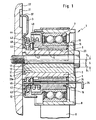
- the longitudinal section according to FIG. 1 illustrates the structure of a clamping device according to the invention 1.
- the clamping device 1 comprises a rotationally symmetrical shaped support body 2, which is positively connected to a shield plate 3.
- the tubular support body 2 is enclosed by an operating eccentric 4, wherein in a ring gap 5, a plain bearing bush 6 is used to achieve a wear-free relative movement of the operating eccentric 4 relative to the support body 2.
- On the outside, on a radially stepped portion of the operating eccentric 4 serves to receive a rolling bearing 7, which in turn is enclosed by a roller 8, which is supported on a traction means 9, in particular a belt.
- a torsion spring 10 inserted between the shield plate 3 and the operating eccentric 4 is provided.
- a longitudinal bore 11 of the support body 2 serves to receive a setting eccentric 12, which is provided at the end remote from the shield plate 3 in one piece with a board 13.
- a stamping 14 of the adjustment eccentric 12 is fixed, but at the same time arranged rotatable relative to the support body 2.
- an axial disc 15 is arranged, which is fixed in position on the operating eccentric 4 via a pin 16.
- a right-angled bent tab 37 of the shield plate 3 is arranged to achieve a positional fixation of the shield plate 3 relative to the machine part 22.
- the adjusting eccentric 12 is further provided with an off-center bore 17 which serves to receive a fastening screw 23, with which the entire clamping device 1 is attached to a machine part 22.
- the FIG. 1 shows the tensioning device 1 in an extreme position in which the bore 17 of the adjustment eccentric 12 with respect to the operating eccentric 4 to achieve a maximum eccentricity "S" are set, which also defines the largest possible adjustment of the clamping device 1.
- the eccentricity "S” defines the maximum distance between the axis of symmetry of the roller 8 and the longitudinal axis of the fastening screw 23.
- Eccentricity "S” forms the sum of the eccentricity "S 1 " of the operating eccentric 4 and the eccentricity "S 2 " of the adjustment eccentric 12.
- the eccentricity "S” can be twice the value of the eccentricity "S 1 ", which corresponds to a measure between the axes of symmetry of the roller 8 and the support body 2 defined.
- FIG. 1 the clamping device 1 is shown with the rotation 20a.
- This rotation 20a ensures a friction or torque-limited fixation between the adjustment eccentric 12 and the support body 2.
- these components by means of a suitable retaining means, an adhesive, for.
- an adhesive for.
- the holding means has a holding force which ensures the positional positioning of these components up to a defined torque.
- the tensioning device 1 further comprises a pin 25 which fits into a bore 24 of the adjustment eccentric 12 is used.
- FIG. 1 Corresponds to the bore 24 with holes in the axial disc 15, the operating eccentric 4 and the shield plate 3.
- the pin 25 allows the completed clamping device 1 biased, ie to deliver in an extreme position of the operating eccentric 4 against the adjusting eccentric 12 to the customer.
- the tensioning device 1 further includes a specially designed angle ring 41, via which the torsion spring 10 is supported with a spring end 42 on the shield plate 3.
- the angle ring 41 made of plastic engages in the installed position with an annularly shaped, radially oriented flange 43 in an axially projecting step 44 of the shield plate 3.
- the flange 43 is provided on the inside with a cylindrical sleeve portion 45 which is externally surrounded by turns of the torsion spring 10.
- the angle ring 41 is integrally connected to a thick-walled disc 46, which is centered on the inside of the support body 2, and is guided while maintaining a radial sealing gap 47 to an end face 48 of the operating eccentric 4.
- the disk 46 On the side facing the operating eccentric 4, the disk 46 is provided with symmetrically circumferentially distributed, axially aligned blind hole-like recesses 49.
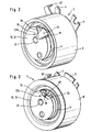
- FIG. 2 shows an anti-rotation 20b, with the operating eccentric 4 relative to the adjustment eccentric 12 is positioned in the pre-assembled state, the delivery state of the clamping device 1, the position.
- this rotation 20b is as in FIG. 1 shown, the positionally fixed on the operating eccentric 4 Axialusion 15 on the outer circumference with an inwardly obliquely directed tab 18 which engages in a recess 19 of the integrally connected to the Einstellexzenter 12 board 13.
- the rotation 20b guarantees in the delivery condition a position-oriented alignment of the adjustment eccentric 12 relative to the operating eccentric 4.
- the anti-rotation device 20b is released by pivoting the flap 18 upwards. This is arranged under the flap 18 Hole 24 accessible, in which a pin 25 can be inserted during assembly, with the basic operating conditions for the components operating eccentric 4, thrust washer 15 and the board 13 and the adjoining adjustment eccentric 12 are rigidly connected.
- FIG. 3 shows the clamping device 1, provided with an alternatively designed anti-rotation lock 20c.
- This is formed by a formed from the axial disc 15 punched leg 26 which projects obliquely at an angle 38 in the recess 19 of the Bordes 13 and thus ensures an effective position position of the Bordes 13 of the adjusting eccentric 12 relative to the operating eccentric 4 in the delivery condition.
- FIG. 4 is the rotation 20d shown in connection with the clamping device 1.
- the axial disc 15 is provided with a locally axially into the recess 19 of the Bordes 13 aligned, offset from the bore 24 arranged embossment which is elastically deformable at a rotation or setting of the board 13 and thus forms a friction or torque-limited rotation 20d ,
- FIG. 5 shows an arranged directly between the operating eccentric 4 and the board 13 and thus the adjustment eccentric 12 anti-rotation 20e.
- a sealing wax point or a suitable further protruding cam or holding means is arranged with a limited adhesive force, so that when setting or rotation of the adjustment eccentric 12 this shears and allows unhindered adjustment.
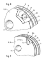
- the rotation 20f according to FIG. 6 is arranged coincident with the bore 24 on the axial disc 15.
- the axial disc 15 has a wall thickness reduced hemispherical shaped spray skin 33, which is surrounded on the outside with symmetrically spaced ball segments 34.
- the design of the rotation 20f allows insertion of the pin 25 for the rigid position positioning of the operating eccentric. 4
- the spray skin 33 is designed in conjunction with the ball segments 34 so that they are elastically deformable with a rotation of the rim 13 relative to the axial disc 15.
- FIG. 7 a detail of the clamping device 1 is shown, which illustrates in particular the design of the rotation 20g.
- the axial disc 15 is provided on the outer circumference partially with an axially projecting lug 31 which forms a radially obliquely inwardly directed leg 32 at the free end, which engages in the recess 19 of the rim 13.
- the FIG. 8 shows a detail of the clamping device 1, which in addition to the rotation 20d has a direction of rotation lock 35.
- the direction of rotation lock 35 prevents rotation of the adjustment eccentric 12 in the clockwise direction and thus a misalignment of the clamping device 1.
- a direction of rotation lock 35 is an axially projecting, attached to the axial disc 15 pin 36 or alternatively used in the operating eccentric pin 4, which passes through a corresponding bore of the axial disc 15 emerges.
- the direction of rotation lock 35 is a security feature that avoids misadjustment and thus ensures effective protection against malfunction of the clamping device 1.
- FIG. 9 the tensioning device 1 is provided with a direction of rotation lock 39, which prevents misadjustment in the counterclockwise direction.
- the rotation direction lock is comparable to the rotational direction lock 35.
- the projection 36 engages in the recess 19 of the adjustment eccentric 12, wherein the maximum rotation of the adjustment eccentric 12 relative to the operating eccentric 4 of stops 40a, 40b of the recess 19 is limited.
Landscapes
- Engineering & Computer Science (AREA)
- General Engineering & Computer Science (AREA)
- Mechanical Engineering (AREA)
- Chairs For Special Purposes, Such As Reclining Chairs (AREA)
Claims (19)
- Dispositif de tensionnement pour un entraînement à moyen de traction, avec lequel un moyen de traction (9), notamment une courroie, peut être précontraint, et en l'occurrence le dispositif de tensionnement (1) comprend:- une plaque de protection (3) supportée sur une partie de machine (22), qui forme un corps porteur (2) à symétrie de révolution;- un excentrique d'ajustage (12) ajustable, inséré dans le corps porteur (2) configuré sous forme cylindrique creuse, qui présente un alésage décalé par rapport à un axe de symétrie et prévu pour recevoir une vis de fixation (23),- un excentrique de fonctionnement (4) entourant le corps porteur (2), ces composants pouvant tourner les uns par rapport aux autres par le biais d'une douille de palier lisse (6);- un palier à roulement (7) disposé sur une surface d'enveloppe de l'excentrique de fonctionnement (4), qui est entouré du côté extérieur par un galet de roulement (8) sur lequel est guidé le moyen de traction (9) lorsque le moyen de traction (9) est précontraint ;- un moyen de ressort, réalisé sous forme de ressort de torsion (10), qui est disposé entre la plaque de protection (3) et l'excentrique de fonctionnement (4), et qui fournit un support par engagement par force du galet de roulement (8) sur le moyen de traction (9) lorsque le moyen de traction (9) est précontraint;caractérisé en ce que- le corps porteur (2) est fixé par engagement par correspondance géométrique sur la plaque de protection (3) et l'excentrique d'ajustage (12) est fixé de manière rotative sur le corps porteur (2) ;- une rondelle axiale (15) est insérée entre le côté frontal de l'excentrique de fonctionnement (4) opposé au ressort de torsion (10) et un bord (13) connecté à l'excentrique d'ajustage (12), et est connectée de manière solidaire en rotation à un excentrique;- le dispositif de tensionnement (1) présente une fixation anti-rotation (20a - 20g) avec laquelle, dans un état brut du dispositif de tensionnement (1), l'excentrique de fonctionnement (4) est positionné par rapport à l'excentrique d'ajustage (12) avec une limitation de couple de friction ou une limitation de couple de rotation.
- Dispositif de tensionnement selon la revendication 1, qui est pourvu d'une barrière au sens de rotation (35, 39), qui permet une rotation de l'excentrique d'ajustage (12) uniquement dans un sens.
- Dispositif de tensionnement selon la revendication 1, dans lequel la rondelle axiale (15) insérée entre l'excentrique de fonctionnement (4) et l'excentrique d'ajustage (12), fixée en position sur l'excentrique de fonctionnement (4), et fabriquée en plastique, forme une fixation anti-rotation (20a - 20g) qui est réalisée de manière à se déformer élastiquement lors d'une rotation de l'excentrique d'ajustage (12).
- Dispositif de tensionnement selon la revendication 3, dans lequel la rondelle axiale (15) présente au moins un rehaussement saillant déformable élastiquement, qui vient en prise, dans l'état brut du dispositif de tensionnement (1), dans un évidement (19) du bord (13) de l'excentrique d'ajustage (12).
- Dispositif de tensionnement selon la revendication 3, dans lequel la rondelle axiale (15) présente au moins un nez moulé par injection ou une came moulée par injection, qui coopère avec l'évidement (19) de l'excentrique d'ajustage (12) ou avec son bord (13).
- Dispositif de tensionnement selon la revendication 3, dans lequel au moins une goupille axiale de la rondelle axiale (15) est adaptée dans l'évidement (19) du bord (13) ou dans un alésage de l'excentrique d'ajustage (12), qui se cisaille dans le cas d'une rotation relative du cylindre d'ajustage (12) par rapport à l'excentrique de fonctionnement (4).
- Dispositif de tensionnement selon la revendication 3, dans lequel la rondelle axiale (15) présente, pour former la fixation anti-rotation (20d), au moins un marquage (14) unilatéral, venant en prise dans l'évidement (19) du cylindre d'ajustage (12).
- Dispositif de tensionnement selon la revendication 3, dont la rondelle axiale (15) présente, pour former la fixation anti-rotation (20f), au moins une peau d'injection (33) d'épaisseur de paroi réduite, saillant axialement, qui vient en prise dans l'évidement (19) du bord (13).
- Dispositif de tensionnement selon la revendication 8, dans lequel la peau d'injection (33) de la fixation anti-rotation (20f) coïncide avec un alésage de l'excentrique de fonctionnement (4) et la position des alésages permet un centrage des composants excentrique d'ajustage (12) et excentrique de fonctionnement (4) au moyen d'un outil séparé.
- Dispositif de tensionnement selon la revendication 3, dans lequel la rondelle axiale (15) présente, en tant que fixation anti-rotation, un degré déformable et/ou cisaillable, qui fixe la position de l'excentrique de fonctionnement (4) par rapport à l'excentrique d'ajustage (12) jusqu'à un certain couple défini de friction ou de rotation.
- Dispositif de tensionnement selon la revendication 3, qui inclut, pour la formation de la fixation anti-rotation, une rondelle axiale (15) qui présente un joint d'injection de forme géométrique correspondant à l'évidement (19) de l'excentrique d'ajustage (12), qui est connecté par point à la rondelle axiale (15).
- Dispositif de tensionnement selon la revendication 3, dans lequel la rondelle axiale (15) inclut, pour la formation de la fixation anti-rotation (20b), une patte (18) qui vient en prise sous forme coudée, par engagement par correspondance géométrique dans l'évidement (19) du bord (13) de l'excentrique d'ajustage (12).
- Dispositif de tensionnement selon la revendication 3, dont la rondelle axiale (14), pour former la fixation anti-rotation (20g), présente, dans la région de la périphérie extérieure, un épaulement saillant axialement (31) qui forme du côté de l'extrémité une branche (32) orientée en biais vers l'intérieur, qui vient en prise par engagement par correspondance géométrique dans l'évidement (19) du bord (13) de l'excentrique d'ajustage (12).
- Dispositif de tensionnement selon la revendication 1, dont la rondelle axiale (15) comprend en partie une branche (26) coudée vers l'intérieur, orientée dans la direction de l'axe de rotation de la rondelle axiale (15), qui pénètre dans l'évidement (19) du bord (13) de l'excentrique d'ajustage (12), pour former la fixation anti-rotation (20c).
- Dispositif de tensionnement selon la revendication 1, dans lequel on prévoit directement entre l'excentrique d'ajustage (12) et l'excentrique de fonctionnement (4) une fixation anti-rotation.
- Dispositif de tensionnement selon la revendication 15, qui comprend, en tant que fixation anti-rotation (20e), au moins un moyen de retenue associé à l'excentrique de fonctionnement (4) ou à l'excentrique d'ajustage (12), qui vient en prise par engagement par correspondance géométrique dans un évidement ou une cavité de l'autre excentrique associé, pour obtenir une fixation anti-rotation avec une limitation de couple de friction ou une limitation de couple de rotation.
- Dispositif de tensionnement selon la revendication 1, dans lequel une fixation anti-rotation (20a) avec une limitation de couple de friction ou une limitation de couple de rotation est prévue entre le corps porteur (2) et l'excentrique d'ajustage (12).
- Dispositif de tensionnement selon la revendication 1, qui présente à la fois une fixation anti-rotation (20d) et une barrière au sens de rotation (35, 39).
- Dispositif de tensionnement selon la revendication 1, dont le ressort de torsion (10) est supporté par une extrémité de ressort (41) par le biais d'une bague coudée (41) sur la plaque de protection (3), la bague coudée (41) entourant les composants bride (43), portion de douille (45) et rondelle (46), qui sont connectés d'une seule pièce les uns aux autres et en l'occurrence la rondelle (46) limite axialement une fente d'étanchéité (47) conjointement avec un côté frontal (48) de l'excentrique de fonctionnement (4).
Applications Claiming Priority (5)
| Application Number | Priority Date | Filing Date | Title |
|---|---|---|---|
| DE2002160552 DE10260552A1 (de) | 2002-12-21 | 2002-12-21 | Spannvorrichtung für einen Zugmitteltrieb |
| DE10260552 | 2002-12-21 | ||
| US45921103P | 2003-03-31 | 2003-03-31 | |
| US459211P | 2003-03-31 | ||
| PCT/EP2003/014306 WO2004057212A1 (fr) | 2002-12-21 | 2003-12-16 | Dispositif de tension pour un entrainement a moyen de traction |
Publications (2)
| Publication Number | Publication Date |
|---|---|
| EP1573229A1 EP1573229A1 (fr) | 2005-09-14 |
| EP1573229B1 true EP1573229B1 (fr) | 2009-12-16 |
Family
ID=32683473
Family Applications (1)
| Application Number | Title | Priority Date | Filing Date |
|---|---|---|---|
| EP03767809A Expired - Lifetime EP1573229B1 (fr) | 2002-12-21 | 2003-12-16 | Dispositif de tension pour un entrainement a moyen de traction |
Country Status (4)
| Country | Link |
|---|---|
| EP (1) | EP1573229B1 (fr) |
| AU (1) | AU2003292246A1 (fr) |
| DE (1) | DE50312248D1 (fr) |
| WO (1) | WO2004057212A1 (fr) |
Families Citing this family (5)
| Publication number | Priority date | Publication date | Assignee | Title |
|---|---|---|---|---|
| DE202007005929U1 (de) * | 2006-12-21 | 2007-12-13 | Schaeffler Kg | Verriegelung einer Exzenter-Spannvorrichtung |
| ITTO20120631A1 (it) * | 2012-07-17 | 2014-01-18 | Lorett S P A | Dispositivo tendicinghia meccanico. |
| ES2940109T3 (es) * | 2017-04-28 | 2023-05-03 | Litens Automotive Inc | Tensor de correa de distribución con construcción mejorada |
| CN110546405B (zh) * | 2017-10-04 | 2023-09-05 | 利滕斯汽车合伙公司 | 具有改进的结构的正时皮带张紧器 |
| WO2023087316A1 (fr) * | 2021-11-22 | 2023-05-25 | 华为技术有限公司 | Appareil et procédé de réglage de courroie de transmission, appareil de direction et véhicule |
Family Cites Families (5)
| Publication number | Priority date | Publication date | Assignee | Title |
|---|---|---|---|---|
| DE4015028A1 (de) * | 1990-05-10 | 1992-01-16 | Skf Gmbh | Voreinstellbare spannvorrichtung |
| DE4209914A1 (de) | 1992-03-27 | 1993-09-30 | Schaeffler Waelzlager Kg | Spannvorrichtung für Riemen oder Ketten |
| DE19729994A1 (de) * | 1997-07-12 | 1999-01-14 | Skf Gmbh | Spannvorrichtung für Treibriemen |
| AU2707799A (en) * | 1998-03-13 | 1999-10-11 | Litens Automotive Partnership | Belt tensioner with reduced tilt action on support structure and method for installing the same |
| DE20220527U1 (de) * | 2001-07-31 | 2003-10-16 | Litens Automotive Partnership, Woodbridge, Ontario | Riemenspanner mit Installationsstift |
-
2003
- 2003-12-16 WO PCT/EP2003/014306 patent/WO2004057212A1/fr not_active Ceased
- 2003-12-16 DE DE50312248T patent/DE50312248D1/de not_active Expired - Lifetime
- 2003-12-16 AU AU2003292246A patent/AU2003292246A1/en not_active Abandoned
- 2003-12-16 EP EP03767809A patent/EP1573229B1/fr not_active Expired - Lifetime
Also Published As
| Publication number | Publication date |
|---|---|
| EP1573229A1 (fr) | 2005-09-14 |
| AU2003292246A1 (en) | 2004-07-14 |
| WO2004057212A1 (fr) | 2004-07-08 |
| DE50312248D1 (de) | 2010-01-28 |
Similar Documents
| Publication | Publication Date | Title |
|---|---|---|
| EP2495453B1 (fr) | Dispositif de fixation doté d'une égalisation de tolérance | |
| DE112012004506B4 (de) | Gurtstraffer für ein Sicherheitsgurtsystem | |
| DE69101747T2 (de) | Haltevorrichtung für eine Welle im Inneren einer Hülse und Anwendung derselben in Kraftfahrzeug-Lenkungen. | |
| WO2002021005A1 (fr) | Poulie de deviation pour un entrainement de mecanisme de traction | |
| EP1805058B1 (fr) | Dispositif de reglage et siege de vehicule | |
| EP1585912B1 (fr) | Unite modulaire munie d'un manchon pour transmission par chaine | |
| WO2011023278A1 (fr) | Ferrure pour siège de véhicule | |
| DE102017121024A1 (de) | Wellgetriebe | |
| DE10161701A1 (de) | Vorrichtung zum Verändern der Steuerzeiten von Gaswechselventilen einer Brennkraftmaschine, insbesondere Einrichtung zur hydraulischen Drehwinkelverstellung einer Nockenwelle gegenüber einer Kurbelwelle | |
| EP1875106B1 (fr) | Dispositif de serrage pour mecanisme de traction | |
| EP1573229A1 (fr) | Dispositif de tension pour un entrainement a moyen de traction | |
| DE102005003844A1 (de) | Verliergesicherte Befestigungsschraube | |
| DE10260552A1 (de) | Spannvorrichtung für einen Zugmitteltrieb | |
| DE10203006B4 (de) | Beschlag für einen Fahrzeugsitz | |
| EP4466165B1 (fr) | Enrouleur de ceinture pour un dispositif de ceinture de sécurité d'un véhicule automobile | |
| DE10021404C2 (de) | Sicherungsscheibe | |
| DE102006019538A1 (de) | Spannrolle oder Umlenkrolle für einen Zugmitteltrieb | |
| DE10322229A1 (de) | Spannvorrichtung für einen Zugmitteltrieb | |
| DE19755496B4 (de) | Abstützring für die Vorlastfeder eines Nehmerzylinders | |
| DE19902169C1 (de) | Befestigungsscheibe und Radanordnung | |
| DE19953379A1 (de) | Reibkonus für eine Spannvorrichtung | |
| EP1454080A1 (fr) | Systeme tendeur pour une transmission par moyen de traction | |
| EP1418111B1 (fr) | Moyeu montable sur tube de colonne de direction | |
| DE202007005928U1 (de) | Exzenter-Spannvorrichtung | |
| DE102019120100A1 (de) | Wellgetriebe und Verfahren zur Montage eines Wellgetriebes |
Legal Events
| Date | Code | Title | Description |
|---|---|---|---|
| PUAI | Public reference made under article 153(3) epc to a published international application that has entered the european phase |
Free format text: ORIGINAL CODE: 0009012 |
|
| 17P | Request for examination filed |
Effective date: 20050520 |
|
| AK | Designated contracting states |
Kind code of ref document: A1 Designated state(s): AT BE BG CH CY CZ DE DK EE ES FI FR GB GR HU IE IT LI LU MC NL PT RO SE SI SK TR |
|
| AX | Request for extension of the european patent |
Extension state: AL LT LV MK |
|
| RAP1 | Party data changed (applicant data changed or rights of an application transferred) |
Owner name: SCHAEFFLER KG |
|
| DAX | Request for extension of the european patent (deleted) | ||
| RBV | Designated contracting states (corrected) |
Designated state(s): DE FR GB IT |
|
| GRAP | Despatch of communication of intention to grant a patent |
Free format text: ORIGINAL CODE: EPIDOSNIGR1 |
|
| GRAS | Grant fee paid |
Free format text: ORIGINAL CODE: EPIDOSNIGR3 |
|
| GRAA | (expected) grant |
Free format text: ORIGINAL CODE: 0009210 |
|
| AK | Designated contracting states |
Kind code of ref document: B1 Designated state(s): DE FR GB IT |
|
| REG | Reference to a national code |
Ref country code: GB Ref legal event code: FG4D Free format text: NOT ENGLISH |
|
| REF | Corresponds to: |
Ref document number: 50312248 Country of ref document: DE Date of ref document: 20100128 Kind code of ref document: P |
|
| RAP2 | Party data changed (patent owner data changed or rights of a patent transferred) |
Owner name: SCHAEFFLER TECHNOLOGIES GMBH & CO. KG |
|
| PLBE | No opposition filed within time limit |
Free format text: ORIGINAL CODE: 0009261 |
|
| STAA | Information on the status of an ep patent application or granted ep patent |
Free format text: STATUS: NO OPPOSITION FILED WITHIN TIME LIMIT |
|
| 26N | No opposition filed |
Effective date: 20100917 |
|
| PG25 | Lapsed in a contracting state [announced via postgrant information from national office to epo] |
Ref country code: IT Free format text: LAPSE BECAUSE OF FAILURE TO SUBMIT A TRANSLATION OF THE DESCRIPTION OR TO PAY THE FEE WITHIN THE PRESCRIBED TIME-LIMIT Effective date: 20091216 |
|
| REG | Reference to a national code |
Ref country code: GB Ref legal event code: 732E Free format text: REGISTERED BETWEEN 20110407 AND 20110413 |
|
| PGFP | Annual fee paid to national office [announced via postgrant information from national office to epo] |
Ref country code: FR Payment date: 20120105 Year of fee payment: 9 |
|
| PGFP | Annual fee paid to national office [announced via postgrant information from national office to epo] |
Ref country code: DE Payment date: 20120229 Year of fee payment: 9 |
|
| PGFP | Annual fee paid to national office [announced via postgrant information from national office to epo] |
Ref country code: GB Payment date: 20120103 Year of fee payment: 9 |
|
| REG | Reference to a national code |
Ref country code: DE Ref legal event code: R081 Ref document number: 50312248 Country of ref document: DE Owner name: SCHAEFFLER TECHNOLOGIES AG & CO. KG, DE Free format text: FORMER OWNER: SCHAEFFLER TECHNOLOGIES GMBH & CO. KG, 91074 HERZOGENAURACH, DE Effective date: 20120828 |
|
| GBPC | Gb: european patent ceased through non-payment of renewal fee |
Effective date: 20121216 |
|
| REG | Reference to a national code |
Ref country code: FR Ref legal event code: ST Effective date: 20130830 |
|
| REG | Reference to a national code |
Ref country code: DE Ref legal event code: R119 Ref document number: 50312248 Country of ref document: DE Effective date: 20130702 |
|
| PG25 | Lapsed in a contracting state [announced via postgrant information from national office to epo] |
Ref country code: DE Free format text: LAPSE BECAUSE OF NON-PAYMENT OF DUE FEES Effective date: 20130702 |
|
| PG25 | Lapsed in a contracting state [announced via postgrant information from national office to epo] |
Ref country code: GB Free format text: LAPSE BECAUSE OF NON-PAYMENT OF DUE FEES Effective date: 20121216 Ref country code: FR Free format text: LAPSE BECAUSE OF NON-PAYMENT OF DUE FEES Effective date: 20130102 |
|
| P01 | Opt-out of the competence of the unified patent court (upc) registered |
Effective date: 20230522 |