EP1573196B1 - Injecteur pourvu d'un dispositif destine a etancheifier une unite d'actionnement et bague d'etancheite - Google Patents
Injecteur pourvu d'un dispositif destine a etancheifier une unite d'actionnement et bague d'etancheite Download PDFInfo
- Publication number
- EP1573196B1 EP1573196B1 EP03813532A EP03813532A EP1573196B1 EP 1573196 B1 EP1573196 B1 EP 1573196B1 EP 03813532 A EP03813532 A EP 03813532A EP 03813532 A EP03813532 A EP 03813532A EP 1573196 B1 EP1573196 B1 EP 1573196B1
- Authority
- EP
- European Patent Office
- Prior art keywords
- crank pin
- ring
- plastic ring
- injector
- housing
- Prior art date
- Legal status (The legal status is an assumption and is not a legal conclusion. Google has not performed a legal analysis and makes no representation as to the accuracy of the status listed.)
- Expired - Lifetime
Links
Images

Classifications
-
- F—MECHANICAL ENGINEERING; LIGHTING; HEATING; WEAPONS; BLASTING
- F02—COMBUSTION ENGINES; HOT-GAS OR COMBUSTION-PRODUCT ENGINE PLANTS
- F02M—SUPPLYING COMBUSTION ENGINES IN GENERAL WITH COMBUSTIBLE MIXTURES OR CONSTITUENTS THEREOF
- F02M61/00—Fuel-injectors not provided for in groups F02M39/00 - F02M57/00 or F02M67/00
- F02M61/16—Details not provided for in, or of interest apart from, the apparatus of groups F02M61/02 - F02M61/14
- F02M61/18—Injection nozzles, e.g. having valve seats; Details of valve member seated ends, not otherwise provided for
- F02M61/188—Spherical or partly spherical shaped valve member ends
-
- F—MECHANICAL ENGINEERING; LIGHTING; HEATING; WEAPONS; BLASTING
- F02—COMBUSTION ENGINES; HOT-GAS OR COMBUSTION-PRODUCT ENGINE PLANTS
- F02M—SUPPLYING COMBUSTION ENGINES IN GENERAL WITH COMBUSTIBLE MIXTURES OR CONSTITUENTS THEREOF
- F02M47/00—Fuel-injection apparatus operated cyclically with fuel-injection valves actuated by fluid pressure
- F02M47/02—Fuel-injection apparatus operated cyclically with fuel-injection valves actuated by fluid pressure of accumulator-injector type, i.e. having fuel pressure of accumulator tending to open, and fuel pressure in other chamber tending to close, injection valves and having means for periodically releasing that closing pressure
- F02M47/027—Electrically actuated valves draining the chamber to release the closing pressure
-
- F—MECHANICAL ENGINEERING; LIGHTING; HEATING; WEAPONS; BLASTING
- F02—COMBUSTION ENGINES; HOT-GAS OR COMBUSTION-PRODUCT ENGINE PLANTS
- F02M—SUPPLYING COMBUSTION ENGINES IN GENERAL WITH COMBUSTIBLE MIXTURES OR CONSTITUENTS THEREOF
- F02M61/00—Fuel-injectors not provided for in groups F02M39/00 - F02M57/00 or F02M67/00
- F02M61/04—Fuel-injectors not provided for in groups F02M39/00 - F02M57/00 or F02M67/00 having valves, e.g. having a plurality of valves in series
- F02M61/10—Other injectors with elongated valve bodies, i.e. of needle-valve type
- F02M61/12—Other injectors with elongated valve bodies, i.e. of needle-valve type characterised by the provision of guiding or centring means for valve bodies
-
- F—MECHANICAL ENGINEERING; LIGHTING; HEATING; WEAPONS; BLASTING
- F02—COMBUSTION ENGINES; HOT-GAS OR COMBUSTION-PRODUCT ENGINE PLANTS
- F02M—SUPPLYING COMBUSTION ENGINES IN GENERAL WITH COMBUSTIBLE MIXTURES OR CONSTITUENTS THEREOF
- F02M61/00—Fuel-injectors not provided for in groups F02M39/00 - F02M57/00 or F02M67/00
- F02M61/16—Details not provided for in, or of interest apart from, the apparatus of groups F02M61/02 - F02M61/14
- F02M61/166—Selection of particular materials
-
- F—MECHANICAL ENGINEERING; LIGHTING; HEATING; WEAPONS; BLASTING
- F02—COMBUSTION ENGINES; HOT-GAS OR COMBUSTION-PRODUCT ENGINE PLANTS
- F02M—SUPPLYING COMBUSTION ENGINES IN GENERAL WITH COMBUSTIBLE MIXTURES OR CONSTITUENTS THEREOF
- F02M61/00—Fuel-injectors not provided for in groups F02M39/00 - F02M57/00 or F02M67/00
- F02M61/16—Details not provided for in, or of interest apart from, the apparatus of groups F02M61/02 - F02M61/14
- F02M61/168—Assembling; Disassembling; Manufacturing; Adjusting
-
- F—MECHANICAL ENGINEERING; LIGHTING; HEATING; WEAPONS; BLASTING
- F02—COMBUSTION ENGINES; HOT-GAS OR COMBUSTION-PRODUCT ENGINE PLANTS
- F02M—SUPPLYING COMBUSTION ENGINES IN GENERAL WITH COMBUSTIBLE MIXTURES OR CONSTITUENTS THEREOF
- F02M2200/00—Details of fuel-injection apparatus, not otherwise provided for
- F02M2200/21—Fuel-injection apparatus with piezoelectric or magnetostrictive elements
-
- F—MECHANICAL ENGINEERING; LIGHTING; HEATING; WEAPONS; BLASTING
- F02—COMBUSTION ENGINES; HOT-GAS OR COMBUSTION-PRODUCT ENGINE PLANTS
- F02M—SUPPLYING COMBUSTION ENGINES IN GENERAL WITH COMBUSTIBLE MIXTURES OR CONSTITUENTS THEREOF
- F02M2200/00—Details of fuel-injection apparatus, not otherwise provided for
- F02M2200/70—Linkage between actuator and actuated element, e.g. between piezoelectric actuator and needle valve or pump plunger
- F02M2200/701—Linkage between actuator and actuated element, e.g. between piezoelectric actuator and needle valve or pump plunger mechanical
-
- F—MECHANICAL ENGINEERING; LIGHTING; HEATING; WEAPONS; BLASTING
- F02—COMBUSTION ENGINES; HOT-GAS OR COMBUSTION-PRODUCT ENGINE PLANTS
- F02M—SUPPLYING COMBUSTION ENGINES IN GENERAL WITH COMBUSTIBLE MIXTURES OR CONSTITUENTS THEREOF
- F02M2200/00—Details of fuel-injection apparatus, not otherwise provided for
- F02M2200/70—Linkage between actuator and actuated element, e.g. between piezoelectric actuator and needle valve or pump plunger
- F02M2200/703—Linkage between actuator and actuated element, e.g. between piezoelectric actuator and needle valve or pump plunger hydraulic
-
- F—MECHANICAL ENGINEERING; LIGHTING; HEATING; WEAPONS; BLASTING
- F02—COMBUSTION ENGINES; HOT-GAS OR COMBUSTION-PRODUCT ENGINE PLANTS
- F02M—SUPPLYING COMBUSTION ENGINES IN GENERAL WITH COMBUSTIBLE MIXTURES OR CONSTITUENTS THEREOF
- F02M2200/00—Details of fuel-injection apparatus, not otherwise provided for
- F02M2200/90—Selection of particular materials
- F02M2200/9015—Elastomeric or plastic materials
Definitions
- crank pin is connected to the plastic ring fuel-tight, so that no aggressive fuel can reach the sensitive actuator.
- a particularly simple method for connecting the plastic ring to the crank pin is seen by vulcanization or gluing. These manufacturing processes are easy to control and cost effective.
- the solution to form the metal ring with respect to its dimensions such that it is in a bore of the housing can be fixed by pressing. With an appropriate tool thus the metal ring can be easily pressed to the desired location of the hole and fixed there.
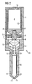
- FIG. 1 shows a schematic representation of a detail of an injector with an actuator and a device with a sealing ring and
- FIG. 2 shows the schematic structure of an injector for the fuel injection.
- the actuator unit 2 has a piezoelectric actuator 8, which is constructed from a piezoceramic with a large number of individual layers according to the PMA technique (piezoelectric multilayer actuator) in order to generate the largest possible stroke.
- the actuator is controlled with a pulsed control voltage, for example 160V, and changes its length in the axial direction according to the applied control pulses. Its upper end is fixedly connected to the housing 1 of the injector (in FIG. 1 not shown), so that the change in length when applying the control voltage to the actuator 8 can affect fully down.
- a sealing ring which has a plastic ring 4 and a metal ring 5 substantially.
- the plastic ring 4 has a central bore through which the crank pin 3 is performed.
- the plastic ring 4 is with the crank pin 3, for example by vulcanization or gluing firmly connected to the crank pin 3, so that no fuel can penetrate.
- the plastic ring 4 is preferably disc-shaped, and has no inaccessible corners or edges on which solid particles can be deposited, resulting for example by a post-processing such as grinding.
- the material for the plastic ring 4 a polymer is provided, which is flexible or elastic and sufficiently resistant to aggressive fuels. Furthermore, the plastic ring 4 must have such flexible properties that are suitable against the prevailing pressure, occurring temperatures, etc., and allow a centered axial guidance of the crank pin 3.
- a recess central bore
- the crank pin 3 is centered and guided by a plastic ring 4.
- the plastic ring 4 is encased by a metal ring 5, which is designed as a sealing ring and a leakage chamber 6 to the injector 8 sealingly closes.
- Position 7 symbolizes the sealing surface between the two parts of the injector housing.
- the actuator 8 If the actuator 8 is activated by applying a control voltage, then it expands and presses on the Hubumsuber 15. This opens the servo valve 18, so that the pressurized fuel can flow partially through a drain 12. The at the lower end of the nozzle needle 10 under higher pressure fuel raises the nozzle needle 10, so that the fuel can escape from the injection ports 14.
Landscapes
- Engineering & Computer Science (AREA)
- Chemical & Material Sciences (AREA)
- Combustion & Propulsion (AREA)
- Mechanical Engineering (AREA)
- General Engineering & Computer Science (AREA)
- Manufacturing & Machinery (AREA)
- Physics & Mathematics (AREA)
- Fluid Mechanics (AREA)
- Fuel-Injection Apparatus (AREA)
Claims (8)
- Injecteur pour l'injection de carburant dans un moteur à combustion interne, comprenant un boîtier (1), une unité actionneur (2) qui, lors de l'actionnement axial de l'actionneur 8, exerce une pression à son extrémité inférieure sur un téton de poussée (3) et un dispositif (5) pour isoler l'unité actionneur (2) à joint étanche d'une chambre de fuite (6) remplie de carburant qui se trouve au-dessous du dispositif (5), caractérisé en ce que le dispositif (5) présente une bague en résine synthétique flexible (4), en ce que la bague en résine synthétique (4) entoure le téton de poussée (3) à joint étanche, en ce qu'il est prévu une bague métallique (5) qui entoure rigidement et à joint étanche la bague en résine synthétique (4) et qui est agencée à joint étanche par rapport au boîtier, et est immobilisée vis-à-vis d'un déplacement axial à l'intérieur du boîtier (1), et en ce que la bague en résine synthétique (4) centre et guide le téton de poussée (3).
- Injecteur selon la revendication 1, caractérisé en ce que la bague en résine synthétique (4) est assemblée, d'une part au téton de poussée (3) et, d'autre part, à la bague métallique (5) à joint étanche au carburant.
- Injecteur selon la revendication 1 ou 2, caractérisé en ce que la bague en résine synthétique (4) est vulcanisée ou collée sur le téton de poussée (3) et/ou sur la bague métallique (5).
- Injecteur selon une des revendications précédentes, caractérisé en ce que la bague en résine synthétique (4) peut être calculée, sous le rapport de ses propriétés de flexibilité et/ou de ses dimensions géométriques, en fonction de la pression de carburant présente dans sa région et/ou de la course de l'unité actionneur (2).
- Injecteur selon une des revendications précédentes, caractérisé en ce que la bague en résine synthétique (5) possède un type d'élastomère qui résiste aux carburants agressifs.
- Injecteur selon une des revendications précédentes, caractérisé en ce que la bague métallique (5) est réalisée, sous le rapport de ses dimensions, de telle manière qu'elle puisse être immobilisée dans un alésage du boîtier (1) par emmanchement à force.
- Injecteur selon une des revendications précédentes, caractérisé en ce que la bague métallique (5) est réalisée, sous le rapport de ses dimensions, de telle manière que l'extrémité inférieure du téton de poussée (3) se termine au même niveau qu'une surface de joint étanche (7) du boîtier (1).
- Injecteur selon une des revendications précédentes, caractérisé en ce qu'une précontrainte pour la bague en résine synthétique (4) peut être réglée par la profondeur d'emmanchement à force de la bague métallique (5).
Applications Claiming Priority (3)
| Application Number | Priority Date | Filing Date | Title |
|---|---|---|---|
| DE10260289 | 2002-12-20 | ||
| DE2002160289 DE10260289A1 (de) | 2002-12-20 | 2002-12-20 | Injektor mit einer Vorrichtung zum Abdichten einer Aktoreinheit sowie Dichtring |
| PCT/DE2003/004150 WO2004057179A1 (fr) | 2002-12-20 | 2003-12-16 | Injecteur pourvu d'un dispositif destine a etancheifier une unite d'actionnement et bague d'etancheite |
Publications (2)
| Publication Number | Publication Date |
|---|---|
| EP1573196A1 EP1573196A1 (fr) | 2005-09-14 |
| EP1573196B1 true EP1573196B1 (fr) | 2008-04-09 |
Family
ID=32477890
Family Applications (1)
| Application Number | Title | Priority Date | Filing Date |
|---|---|---|---|
| EP03813532A Expired - Lifetime EP1573196B1 (fr) | 2002-12-20 | 2003-12-16 | Injecteur pourvu d'un dispositif destine a etancheifier une unite d'actionnement et bague d'etancheite |
Country Status (3)
| Country | Link |
|---|---|
| EP (1) | EP1573196B1 (fr) |
| DE (2) | DE10260289A1 (fr) |
| WO (1) | WO2004057179A1 (fr) |
Families Citing this family (4)
| Publication number | Priority date | Publication date | Assignee | Title |
|---|---|---|---|---|
| EP1808596A1 (fr) | 2006-01-12 | 2007-07-18 | Siemens Aktiengesellschaft | Assemblage de soupape pour un injecteur et l'injecteur |
| EP1970556B1 (fr) | 2007-03-15 | 2009-12-30 | Ford Global Technologies, LLC | Injecteur |
| DE102011084107A1 (de) | 2011-10-06 | 2013-04-11 | Continental Automotive Gmbh | Piezoelektrischer Aktuator |
| DE102014207378B4 (de) * | 2014-04-17 | 2017-08-10 | Continental Automotive Gmbh | Einspritzventilvorrichtung für ein Hochdrucksystem |
Family Cites Families (3)
| Publication number | Priority date | Publication date | Assignee | Title |
|---|---|---|---|---|
| DE3742241A1 (de) * | 1987-02-14 | 1988-08-25 | Daimler Benz Ag | Piezosteuerventil zur steuerung der kraftstoffeinspritzung ueber ein einspritzventil bei brennkraftmaschinen |
| DE19946603B4 (de) * | 1999-09-29 | 2009-01-15 | Robert Bosch Gmbh | Brennstoffeinspritzventil mit kompensierenden Dichtelementen |
| DE10004810A1 (de) * | 2000-02-04 | 2001-08-16 | Bosch Gmbh Robert | Hydraulisches Hub-Übersetzungssystem |
-
2002
- 2002-12-20 DE DE2002160289 patent/DE10260289A1/de not_active Ceased
-
2003
- 2003-12-16 WO PCT/DE2003/004150 patent/WO2004057179A1/fr not_active Ceased
- 2003-12-16 EP EP03813532A patent/EP1573196B1/fr not_active Expired - Lifetime
- 2003-12-16 DE DE50309597T patent/DE50309597D1/de not_active Expired - Lifetime
Also Published As
| Publication number | Publication date |
|---|---|
| EP1573196A1 (fr) | 2005-09-14 |
| DE50309597D1 (de) | 2008-05-21 |
| DE10260289A1 (de) | 2004-07-08 |
| WO2004057179A1 (fr) | 2004-07-08 |
Similar Documents
| Publication | Publication Date | Title |
|---|---|---|
| DE10139857B4 (de) | Ventil zum Steuern von Flüssigkeiten | |
| WO2008138800A1 (fr) | Injecteur à actionneur piézoélectrique | |
| EP1989436A1 (fr) | Dispositif d'injection de carburant pour moteur a combustion interne | |
| DE102009000183A1 (de) | Brennstoffeinspritzventil | |
| EP1421271B1 (fr) | Soupape d'injection de carburant | |
| WO2010142767A1 (fr) | Soupape d'injection avec unité de transfert | |
| EP1573196B1 (fr) | Injecteur pourvu d'un dispositif destine a etancheifier une unite d'actionnement et bague d'etancheite | |
| WO2005124153A1 (fr) | Pompe haute pression conçue pour un dispositif d'injection de carburant d'un moteur a combustion interne | |
| DE102009024595A1 (de) | Einspritzventil mit Übertragungseinheit | |
| EP3034857A1 (fr) | Soupape d'injection de combustible | |
| EP1043497B1 (fr) | Soupape de commande | |
| DE102006017034B4 (de) | Piezo-Aktor, Verfahren zum Herstellen eines Piezo-Aktors und Einspritzsystem mit einem solchen | |
| DE102006009659A1 (de) | Kraftstoff-Einspritzvorrichtung für eine Brennkraftmaschine mit Kraftstoff-Direkteinspritzung | |
| DE102009002742A1 (de) | Kraftstoff-Injektor | |
| DE102004054589B4 (de) | Steuerventil und Einspritzventil | |
| DE10251587B4 (de) | Ventil zum Steuern eines Fluidstroms | |
| EP1325228B1 (fr) | Soupape d'injection avec piston de pompe | |
| WO2016188651A1 (fr) | Dispositif de soupape de commande électromagnétique | |
| EP1576279A1 (fr) | Soupape d'injection de carburant | |
| DE102012218732B4 (de) | Verfahren zur Herstellung eines Einspritzventils | |
| DE102010029123A1 (de) | Kraftstoffinjektor mit hydraulischer Kopplereinheit | |
| EP2439398A1 (fr) | Soupape d'injection de combustible | |
| DE102004031308B4 (de) | Hydraulischer Koppler | |
| DE102014225999A1 (de) | Brennstoffeinspritzventil | |
| DE102011089130A1 (de) | Kraftstoffeinspritzventil |
Legal Events
| Date | Code | Title | Description |
|---|---|---|---|
| PUAI | Public reference made under article 153(3) epc to a published international application that has entered the european phase |
Free format text: ORIGINAL CODE: 0009012 |
|
| 17P | Request for examination filed |
Effective date: 20050406 |
|
| AK | Designated contracting states |
Kind code of ref document: A1 Designated state(s): AT BE BG CH CY CZ DE DK EE ES FI FR GB GR HU IE IT LI LU MC NL PT RO SE SI SK TR |
|
| RBV | Designated contracting states (corrected) |
Designated state(s): DE FR GB IT |
|
| GRAP | Despatch of communication of intention to grant a patent |
Free format text: ORIGINAL CODE: EPIDOSNIGR1 |
|
| GRAS | Grant fee paid |
Free format text: ORIGINAL CODE: EPIDOSNIGR3 |
|
| GRAA | (expected) grant |
Free format text: ORIGINAL CODE: 0009210 |
|
| RAP1 | Party data changed (applicant data changed or rights of an application transferred) |
Owner name: VDO AUTOMOTIVE AG |
|
| AK | Designated contracting states |
Kind code of ref document: B1 Designated state(s): DE FR GB IT |
|
| REG | Reference to a national code |
Ref country code: GB Ref legal event code: FG4D Free format text: NOT ENGLISH |
|
| REF | Corresponds to: |
Ref document number: 50309597 Country of ref document: DE Date of ref document: 20080521 Kind code of ref document: P |
|
| RAP2 | Party data changed (patent owner data changed or rights of a patent transferred) |
Owner name: CONTINENTAL AUTOMOTIVE GMBH |
|
| ET | Fr: translation filed | ||
| PLBE | No opposition filed within time limit |
Free format text: ORIGINAL CODE: 0009261 |
|
| STAA | Information on the status of an ep patent application or granted ep patent |
Free format text: STATUS: NO OPPOSITION FILED WITHIN TIME LIMIT |
|
| 26N | No opposition filed |
Effective date: 20090112 |
|
| PGFP | Annual fee paid to national office [announced via postgrant information from national office to epo] |
Ref country code: FR Payment date: 20081212 Year of fee payment: 6 |
|
| GBPC | Gb: european patent ceased through non-payment of renewal fee |
Effective date: 20081216 |
|
| PG25 | Lapsed in a contracting state [announced via postgrant information from national office to epo] |
Ref country code: IT Free format text: LAPSE BECAUSE OF FAILURE TO SUBMIT A TRANSLATION OF THE DESCRIPTION OR TO PAY THE FEE WITHIN THE PRESCRIBED TIME-LIMIT Effective date: 20080409 |
|
| PG25 | Lapsed in a contracting state [announced via postgrant information from national office to epo] |
Ref country code: GB Free format text: LAPSE BECAUSE OF NON-PAYMENT OF DUE FEES Effective date: 20081216 |
|
| REG | Reference to a national code |
Ref country code: FR Ref legal event code: ST Effective date: 20100831 |
|
| PG25 | Lapsed in a contracting state [announced via postgrant information from national office to epo] |
Ref country code: FR Free format text: LAPSE BECAUSE OF NON-PAYMENT OF DUE FEES Effective date: 20091231 |
|
| REG | Reference to a national code |
Ref country code: DE Ref legal event code: R084 Ref document number: 50309597 Country of ref document: DE |
|
| REG | Reference to a national code |
Ref country code: DE Ref legal event code: R081 Ref document number: 50309597 Country of ref document: DE Owner name: VITESCO TECHNOLOGIES GMBH, DE Free format text: FORMER OWNER: CONTINENTAL AUTOMOTIVE GMBH, 30165 HANNOVER, DE |
|
| PGFP | Annual fee paid to national office [announced via postgrant information from national office to epo] |
Ref country code: DE Payment date: 20201231 Year of fee payment: 18 |
|
| REG | Reference to a national code |
Ref country code: DE Ref legal event code: R081 Ref document number: 50309597 Country of ref document: DE Owner name: VITESCO TECHNOLOGIES GMBH, DE Free format text: FORMER OWNER: VITESCO TECHNOLOGIES GMBH, 30165 HANNOVER, DE |
|
| REG | Reference to a national code |
Ref country code: DE Ref legal event code: R119 Ref document number: 50309597 Country of ref document: DE |
|
| PG25 | Lapsed in a contracting state [announced via postgrant information from national office to epo] |
Ref country code: DE Free format text: LAPSE BECAUSE OF NON-PAYMENT OF DUE FEES Effective date: 20220701 |