EP1325228B1 - Soupape d'injection avec piston de pompe - Google Patents
Soupape d'injection avec piston de pompe Download PDFInfo
- Publication number
- EP1325228B1 EP1325228B1 EP01980177A EP01980177A EP1325228B1 EP 1325228 B1 EP1325228 B1 EP 1325228B1 EP 01980177 A EP01980177 A EP 01980177A EP 01980177 A EP01980177 A EP 01980177A EP 1325228 B1 EP1325228 B1 EP 1325228B1
- Authority
- EP
- European Patent Office
- Prior art keywords
- valve
- chamber
- injection
- line
- injection valve
- Prior art date
- Legal status (The legal status is an assumption and is not a legal conclusion. Google has not performed a legal analysis and makes no representation as to the accuracy of the status listed.)
- Expired - Lifetime
Links
- 238000002347 injection Methods 0.000 title claims description 103
- 239000007924 injection Substances 0.000 title claims description 103
- 238000007789 sealing Methods 0.000 claims description 54
- 239000000446 fuel Substances 0.000 claims description 23
- 239000007921 spray Substances 0.000 claims 1
- 238000002485 combustion reaction Methods 0.000 description 6
- 239000012530 fluid Substances 0.000 description 6
- 238000005086 pumping Methods 0.000 description 5
- 238000004891 communication Methods 0.000 description 4
- 238000009825 accumulation Methods 0.000 description 3
- 238000000034 method Methods 0.000 description 3
- 230000006835 compression Effects 0.000 description 2
- 238000007906 compression Methods 0.000 description 2
- 239000002283 diesel fuel Substances 0.000 description 2
- 238000006073 displacement reaction Methods 0.000 description 2
- 238000004519 manufacturing process Methods 0.000 description 2
- 230000007704 transition Effects 0.000 description 2
- 230000007423 decrease Effects 0.000 description 1
- 230000000694 effects Effects 0.000 description 1
- 238000009434 installation Methods 0.000 description 1
- 238000003825 pressing Methods 0.000 description 1
Images


Classifications
-
- F—MECHANICAL ENGINEERING; LIGHTING; HEATING; WEAPONS; BLASTING
- F02—COMBUSTION ENGINES; HOT-GAS OR COMBUSTION-PRODUCT ENGINE PLANTS
- F02M—SUPPLYING COMBUSTION ENGINES IN GENERAL WITH COMBUSTIBLE MIXTURES OR CONSTITUENTS THEREOF
- F02M57/00—Fuel-injectors combined or associated with other devices
- F02M57/02—Injectors structurally combined with fuel-injection pumps
- F02M57/022—Injectors structurally combined with fuel-injection pumps characterised by the pump drive
- F02M57/025—Injectors structurally combined with fuel-injection pumps characterised by the pump drive hydraulic, e.g. with pressure amplification
-
- F—MECHANICAL ENGINEERING; LIGHTING; HEATING; WEAPONS; BLASTING
- F02—COMBUSTION ENGINES; HOT-GAS OR COMBUSTION-PRODUCT ENGINE PLANTS
- F02M—SUPPLYING COMBUSTION ENGINES IN GENERAL WITH COMBUSTIBLE MIXTURES OR CONSTITUENTS THEREOF
- F02M59/00—Pumps specially adapted for fuel-injection and not provided for in groups F02M39/00 -F02M57/00, e.g. rotary cylinder-block type of pumps
- F02M59/02—Pumps specially adapted for fuel-injection and not provided for in groups F02M39/00 -F02M57/00, e.g. rotary cylinder-block type of pumps of reciprocating-piston or reciprocating-cylinder type
- F02M59/10—Pumps specially adapted for fuel-injection and not provided for in groups F02M39/00 -F02M57/00, e.g. rotary cylinder-block type of pumps of reciprocating-piston or reciprocating-cylinder type characterised by the piston-drive
- F02M59/105—Pumps specially adapted for fuel-injection and not provided for in groups F02M39/00 -F02M57/00, e.g. rotary cylinder-block type of pumps of reciprocating-piston or reciprocating-cylinder type characterised by the piston-drive hydraulic drive
-
- F—MECHANICAL ENGINEERING; LIGHTING; HEATING; WEAPONS; BLASTING
- F02—COMBUSTION ENGINES; HOT-GAS OR COMBUSTION-PRODUCT ENGINE PLANTS
- F02M—SUPPLYING COMBUSTION ENGINES IN GENERAL WITH COMBUSTIBLE MIXTURES OR CONSTITUENTS THEREOF
- F02M59/00—Pumps specially adapted for fuel-injection and not provided for in groups F02M39/00 -F02M57/00, e.g. rotary cylinder-block type of pumps
- F02M59/44—Details, components parts, or accessories not provided for in, or of interest apart from, the apparatus of groups F02M59/02 - F02M59/42; Pumps having transducers, e.g. to measure displacement of pump rack or piston
- F02M59/46—Valves
- F02M59/466—Electrically operated valves, e.g. using electromagnetic or piezoelectric operating means
- F02M59/468—Electrically operated valves, e.g. using electromagnetic or piezoelectric operating means using piezoelectric operating means
-
- Y—GENERAL TAGGING OF NEW TECHNOLOGICAL DEVELOPMENTS; GENERAL TAGGING OF CROSS-SECTIONAL TECHNOLOGIES SPANNING OVER SEVERAL SECTIONS OF THE IPC; TECHNICAL SUBJECTS COVERED BY FORMER USPC CROSS-REFERENCE ART COLLECTIONS [XRACs] AND DIGESTS
- Y10—TECHNICAL SUBJECTS COVERED BY FORMER USPC
- Y10T—TECHNICAL SUBJECTS COVERED BY FORMER US CLASSIFICATION
- Y10T137/00—Fluid handling
- Y10T137/8593—Systems
- Y10T137/86928—Sequentially progressive opening or closing of plural valves
- Y10T137/86936—Pressure equalizing or auxiliary shunt flow
- Y10T137/86944—One valve seats against other valve [e.g., concentric valves]
- Y10T137/86976—First valve moves second valve
Definitions
- the invention relates to an injection valve with a pump piston according to the preamble of patent claim 1.
- Injectors with pump piston to increase the pressure of the injected fluid are used for example in automotive engineering to achieve very high injection pressures.
- diesel fuel is injected in modern common rail injection systems with a pressure of up to 2000 bar in the combustion chamber of an internal combustion engine.
- a fuel injection device for internal combustion engines is known, is supplied to the fuel from a high-pressure accumulation chamber an injection valve.
- the fuel is guided into a pump chamber which is delimited by a first end face of a pump piston.
- a second end face of the pump piston adjoins an amplifier chamber, in which an injection needle is arranged.
- the injection needle is biased against a sealing seat, so that in a closed position, the booster chamber is separated from injection holes.
- the injection needle communicates with a second piston adjacent to a control chamber.
- the control chamber communicates with a 3/2-way valve via a bore.
- the 3/2-way valve is also connected via a second line to a high-pressure accumulator and via a third line to a discharge line.
- a presettable pressure in the control chamber is set, thereby controlling the position of the injection needle.
- a further controllable valve is provided, which connects the high-pressure accumulation chamber with the pump chamber as a function of the switching position of the controllable valve.
- an injection process is controlled.
- an injection valve which has a booster piston.
- a supply line is guided via a first controllable valve to a pump chamber.
- An end face of the piston has a raised contact surface, wherein the booster chamber is connectable via a second valve with a fuel reservoir.
- a fuel injection device for internal combustion engines which has a housing which comprises an inlet power, which is guided via a controllable valve to a pump chamber.
- the fuel is guided into a pump space which is delimited by an end face of a pump piston.
- a second end face of the pump piston is adjacent to a pressure chamber communicating with a nozzle space of the injection needle.
- the injection needle is biased against a sealing seat, so that in a closed position, the pressure chamber is separated from injection holes.
- the injection needle communicates with a pressure piece which adjoins a control chamber.
- the control chamber is connected via throttles with the pressure chamber and the nozzle chamber on the one hand and with a 2/2-way valve on the other hand in conjunction.
- the pressure piece is pressurized in the closing direction.
- the pressure in the control chamber is reduced, so that in the sequence acting in the opening direction on the valve member pressure force in the nozzle chamber exceeds the force acting in the closing direction on the valve member pressure force.
- the valve sealing surface lifts off the valve seat surface and fuel is injected. In this case, the pressure relief process of the control chamber and thus the stroke control of the valve member on the dimensioning of the two throttles can be influenced.
- the object of the invention is to provide a simplified injection valve.
- An advantage of the invention is that two controllable valves are not required, but the injection is controlled by a single valve. The only valve is in the supply line before Pump room arranged. This provides a cost effective injector that also allows precise control of the injection.
- the inventive valve consists in the use of a 3/2-way valve, wherein a first line connection to a supply line, a second line connection to a first supply line and a third line connection is connected to a discharge line.
- a first valve chamber is provided with a first closing member, wherein the feed line opens into the first valve chamber and the first closing member in response to the switching position keeps a drain opening open or closes.
- a preferred embodiment of a first closing member and a first sealing seat consists in a conical sealing surface, through which a simple and secure sealing of the first valve chamber is made possible.
- the first closing member is connected via a rod with a second closing member.
- the second closure member is disposed in a second valve chamber and the rod is passed through a communication bore connecting the first and second valve chambers.
- a discharge line is connected to the second valve chamber. Depending on the switching position of the valve, either the discharge line or the supply line is connected to the supply line.
- the second valve member is in operative connection with an actuator, which adjusts the switching position of the first and second closing member.
- an actuator which adjusts the switching position of the first and second closing member.
- the first and second valve chambers are arranged along an axis which is arranged either parallel or on a central axis of symmetry of the injection valve. In this way, a narrow design of the injection valve is achieved.
- a piezoelectric actuator which actuates the valve.
- the piezoelectric actuator is provided at the upper end of the housing, wherein the piezoelectric actuator is partially inserted into the housing.
- a narrow design is achieved.
- the piezoelectric actuator is arranged centrally symmetrical to the injection valve, whereby a particularly narrow-fitting shape of the injection valve is provided.
- the third and fourth sealing surfaces of the second valve chamber and the second closing member are formed as a flat surface.
- the functionality of the pump piston is preferably improved in that the first end face has a shoulder which can be brought into abutment against a contact surface on the housing, the supply line opening into the pumping chamber in the area of the contact surface. In this way it is ensured that even with maximum deflection of the pump piston, a residual volume of the pumping chamber is maintained and thus when a connection of the pumping chamber with the supply line, the pumping chamber quickly filled with fluid, whereby a rapid increase in pressure in the injection chamber is achieved. Due to the rapid increase in pressure, precise control of the start of injection is possible.
- Fig. 1 shows schematically an injection valve 1 with a Mittensymmetrieachse 19, as used for example for the injection of diesel fuel in a diesel internal combustion engine.
- the injection valve 1 has a valve body 3, which is connected via a clamping sleeve 43 with a pump body 4.
- the pump body 4 is connected via a clamping nut 40 with an intermediate plate 46, a spring body 42 and a nozzle body 5.
- the valve body 3 has an inlet connection 9, which communicates with an inlet line 10.
- the supply line 10 is guided to a first valve chamber 11.
- the first valve chamber 11 is part of a through hole 56, which is guided centrally symmetrically by the valve body 3.
- an actuator 18 is screwed in the upper end, which seals the through hole 56 upwards.
- a contact plate 21 is provided, which rests on an annular edge on the pump body 4 and is pressed by the pump body 4 against the valve body 3 and the through hole 56 seals down. In this case, the contact plate 21 limits the first valve chamber 11.
- a valve 14 is provided, which is designed as a 3/2-way valve.
- the valve 14 has as connections the supply line 10, a first supply line 20 and a discharge line 47. Depending on the position of the valve 14, either the supply line 10 or the discharge line 47 is connected to the first supply line 20.
- the first supply line 20 is guided through a bore 70 of the contact plate 21 to a pump chamber 22.
- a movable pump piston 64 is arranged in the pump body 4, which defines the pump space 22 with a first end face 24, which is formed between the contact plate 21 and the first end face 24 in the pump body 4.
- the pump piston 64 has in the upper region a cup-shaped sleeve 25, which is sealingly guided in the pump body 4 and the first end face 24 has.
- a booster piston 23 is arranged, which is biased by a second spring element 26 in the direction of the first end face 24.
- the second spring element 26 is supported against a step of the pump body 4.
- an abutment ring is formed, on which the second spring element 26 abuts.
- the booster piston 23 is at its lower end in a guide bore 65 of the pump body 4 sealed.
- the booster piston 23 has a second end face 28, which has a smaller cross-section than the first end face 24 and defines an amplifier chamber 29, which is formed in the pump body 4.
- sealing elements 66 are arranged between the pump body 4 and the booster piston 23, which effect a sealing of the booster chamber 29.
- a sealing element for example, a sealing ring is used.
- the pump body 4 rests on the intermediate plate 46.
- the booster chamber 29 is bounded by the intermediate plate 46, the pump body 4 and the booster piston 23.
- a first bore 67 is introduced, which connects the booster chamber 29 with a third supply line 32, which is introduced into the spring body 42.
- the spring body 42 abuts against the intermediate plate 46.
- a second supply line 31 is introduced into the intermediate plate 46, which forms a connection between the booster chamber 29 and a fuel chamber 53 via an inlet valve 30.
- the fuel chamber 53 is supplied with fuel via channels, which are not shown, which has a low pressure.
- the inlet valve 30 ensures that the booster chamber 29 is always completely filled with fuel.
- the third supply line 32 is guided to the nozzle body 5 and opens in the nozzle body 5 in a fourth supply line 54, which is guided to an injection space 34.
- an injection needle 6 is arranged axially movable, which has a pressure surface 35 in the region of the injection chamber 34.
- the injection needle 6 has a needle tip 36, which is arranged in the region of the tip of the nozzle body 5.
- the needle tip 36 has a needle seat 37, which is arranged above the injection holes 8 and associated with a sealing seat 69 which is formed on the nozzle body. Sits the injection needle 6 with If the injection needle 6 but lifted with the needle seat 37 from the sealing seat 69, so there is a hydraulic connection between the injection chamber 34 and the injection holes 8, so that fuel is discharged from the injection space 34 via the injection holes 8.
- the injection needle 6 has in the upper region a guide section 55 which is sealingly guided in a guide bore of the nozzle body 5.
- the guide portion 55 is in communication with a connecting rod 38 which is guided in the spring body 42.
- the connecting rod 38 is in communication with a third spring element 39, which is arranged in a spring chamber 68 in the spring body 42.
- the third spring element 39 is supported against the intermediate plate 46 and biases the injection needle 6 in the direction of the sealing seat 69, which is arranged above the injection holes 8. If a low fuel pressure is present in the injection space 34, the injection needle 6 is pressed onto the sealing seat 69 by the third spring element 39, so that there is no connection between the pump space 34 and the injection holes 8.
- the pressure in the injection chamber 34 is increased by a compression movement of the booster piston 23, the pressure acts on the pressure surface 35 and lifts the injection needle 6 after reaching a Abhebedruckes against the bias of the third spring element 39 from the sealing seat, so that a hydraulic connection between the injection space and the injection holes 8 is present. In this position, the injection needle 6 fuel is discharged from the injection chamber 34 via the injection holes 8.
- Fuel which escapes via a sealing gap of the guide section 55 of the injection needle 6 is discharged via a leakage valve 41 to the fuel chamber 53.
- the valve 14 controls in dependence on the switching position, the pressure in the pump chamber 22 and thus the compression stroke of the booster piston 23.
- the surface of the first end face 24 is greater than the surface of the second end face 28, so that a pressure increase between the pressure in the pump chamber 22nd and the pressure in the booster chamber 29 and in the injection space 34 is reached.
- valve 14 The operation of the valve 14 will be explained in more detail with reference to FIG. 2.
- Fig. 2 shows an enlarged view of the valve body 3.
- the valve body 3 has the central through-hole 56 which is sealed in the upper region by the actuator 18 and in the lower region by the contact plate 21.
- the through hole 56 has an upper first portion 57, in which the actuator 18 is screwed to the housing.
- the first section 57 merges via a step into a second section 58, which represents a second valve chamber 17.
- the second section 58 has a smaller cross section than the first section 57.
- the second section 58 merges into a third section 59, wherein the third section 59 has a smaller cross section than the second section 58.
- the third section 59 merges via a step into a fourth section 60, which has a larger cross section than the third section 59.
- the fourth section 60 merges via a step into a fifth section 61, which has a larger cross section than the fourth section 60.
- the fifth section 61 represents the first valve chamber 11.
- the actuator 18 is preferably designed as a piezoelectric actuator having electrical connections 45. To the electrical connections 45 control lines are connected, which are in communication with a control unit. The control unit controls the actuator 18 according to predetermined methods depending on operating parameters of the internal combustion engine.
- the actuator 18 is in operative connection with a second closing member 15, wherein the second closing member 15 is arranged in the second valve chamber 17.
- the second closing member 15 has a fourth sealing surface 51, which is associated with a third sealing surface 50.
- the third sealing surface 50 is formed on the valve body 3 in the transition region between the second and the third section 58, 59.
- the second closing member 15 has a rod 16 which is guided through the third section 59 and the fourth section 60 to the first valve chamber 11.
- the rod 16 communicates with a first closing member 13, which is arranged substantially in the first valve chamber 11.
- the first closing member 13 has a second sealing surface 49, which is assigned to a first sealing surface 48.
- the first sealing surface 48 is arranged on the valve body 3 in the transition region between the fourth and fifth sections 60, 61.
- a first spring element 12 is arranged, which biases the first closing member 13 in the direction of the first sealing surface 48.
- the second sealing surface 49 of the first closing member 13 and the fourth sealing surface 51 of the second closing member 15 are preferably formed as conical surfaces.
- the third and first sealing surfaces 50, 48 are preferably designed correspondingly as conical surfaces in order to ensure a secure sealing with the aid of the first and second closing members 13, 15.
- the first and the second closing member 13, 15 are spaced over the rod 16 in the manner and firmly connected to each other, that depending on the deflection position of the actuator 18, the first or second closing member 13, 15 rests on the associated sealing seat 48, 50 and thus either the Supply line 10 or the discharge line 47 is connected to the first supply line 20.
- This is the Bar 16 is formed with a smaller cross-section than the through-hole 56 in the third and fourth sections 59, 60th
- the fourth section 60 has an enlarged annular channel 62, to which the first supply line 20 is connected. Thus, an improved hydraulic supply of the pump chamber 22 is ensured.
- the actuator 18 is not activated and the first closing member 13 abuts against the associated sealing seat 48, so that there is no connection between the connection 9 and the pumping space 22.
- the pump piston 64 is in the uppermost position by the bias of the second spring element 26 and no high pressure in the injection chamber 34 is generated. Consequently, the injection needle 6 is pressed by the third spring element 39 on the associated sealing seat 69 and there is no connection between the injection chamber 34 and the injection holes 8 before.
- the pump chamber 22 is connected to the relief line 47 via the first supply line 20, the fourth, third and second sections 60, 59, 58.
- the relief line 47 is connected to a return line and has only a low pressure. Thus prevails in the pump chamber 22 only low pressure.
- the first end face 24 has an elevated contact surface 63, which can be brought into contact with the contact plate 21 when the pump chamber 22 is depressurized.
- the abutment surface 63 is preferably annular and has the advantage that in the region of the bore 70, via which the first supply line 20 opens into the pump chamber 22, the first end face 24 has a predetermined distance from the abutment plate 21, so that there is always a residual volume in the Pump space 22 is present.
- the valve 14 is opened, fluid is forced into the pump chamber 22 and lies at the predetermined pressure on the entire surface of the first Front side 24, so that a displacement of the pump piston takes place quickly.
- the control unit actuates the actuator 18 in such a way that it deflects downward, thereby pressing the second closing element 15 with the fourth sealing surface 51 onto the associated third sealing surface 50 and thus the connection between the relief line 47 and the first supply line 20 interrupts.
- the first closing member 13 is pushed away from the first sealing surface 48 by the displacement of the second closing member 15 via the rod 16 and thus opens a connecting cross section between the first supply line 20 and the supply line 10.
- the supply line 10 is connected via the inlet connection 9 with a fluid reservoir, preferably a fuel reservoir with a predetermined pressure in connection.
- the fluid flows with a predetermined pressure in the pump chamber 22 and pushes the pump piston 64 against the biasing force of the second spring element 26 down toward the booster chamber 29.
- the booster chamber 29 is completely filled with fuel, so that the pressure on the first bore 67th , the fourth supply line 54 and the third supply line 32 in the injection space 34 is increased. If the pressure in the injection space 34 exceeds a predetermined lift-off pressure, the injection needle 6 is lifted off the sealing seat by the pressure on the pressure surface 35 against the biasing force of the third spring element 39, so that fuel is discharged from the injection space 34 via the injection holes 8.
- a fuel reservoir a so-called common rail is provided as a fuel reservoir, with which the inlet port 9 is supplied with fuel under pressure of up to 500 bar.
- the actuator is driven accordingly, that it retracts upwards.
- the first and second closing member 13, 15 is moved by the first spring element 12 in the closed position, wherein the first closing member 13 comes into contact with the first sealing surface 48 and the second closing member 15 is lifted from the third sealing surface 50 upwards. Consequently, the connection between the supply line 10 and the first supply line 20 is interrupted and the first supply line 20 is again connected to the discharge line 47. Thus, the fluid in the pump chamber 22 escapes via the relief line 47. Thus, the booster piston 23 is moved by the second spring element 26 upwards. As a result, the pressure in the injection space 34 decreases and the injection needle 6 is pressed by the third spring element 39 onto the sealing seat 69. After installation of the injection needle 6 at the sealing seat 69, the connection between the injection chamber 34 and the injection holes 8 is interrupted, so that the injection is completed.
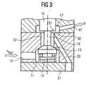
- FIG. 3 shows a further embodiment of the invention in which the second closing member 15, as the fourth sealing surface 51, has a planar surface which is associated with a correspondingly planar third sealing surface 50.
- a plurality of first supply lines 20 are provided, which connect the valve 14 to the pump chamber 24.
Landscapes
- Engineering & Computer Science (AREA)
- Chemical & Material Sciences (AREA)
- Combustion & Propulsion (AREA)
- Mechanical Engineering (AREA)
- General Engineering & Computer Science (AREA)
- Physics & Mathematics (AREA)
- Electromagnetism (AREA)
- Fuel-Injection Apparatus (AREA)
Claims (12)
- Injecteur comprenant un boîtier, une conduite d'admission (10) guidée vers une chambre de pompe (22) par une première soupape commandable (14) et une première conduite d'alimentation (20),
comprenant un piston (64) qui délimite la chambre de pompe (22) avec une première face frontale (24), cette première face frontale (24) présentant une surface d'appui plus élevée (63) qui peut être amenée en appui contre une plaque d'appui (21),
le piston (64) délimitant une chambre d'amplification (29) avec une deuxième face frontale (28),
la chambre d'amplification (29) pouvant être reliée à un réservoir de carburant par une deuxième soupape (30),
comprenant une chambre d'injection (34) qui est en liaison avec la chambre d'amplification (29),
comprenant une aiguille d'injection (6) qui se déplace dans la chambre d'injection (34),
l'aiguille d'injection (6) présentant une surface de pression (35) disposée dans la chambre d'injection (34),
l'aiguille d'injection (6) ouvrant ou fermant une section de liaison entre la chambre d'injection (34) et un orifice d'injection (8) en fonction d'une position de commutation,
une pression régnant dans la chambre de pompe (22) étant transférée par le piston (64) en une pression plus élevée dans la chambre d'amplification (29) et la chambre d'injection (34), la position de commutation de l'aiguille d'injection étant réglée par la pression régnant dans la chambre de pression (22) et l'aiguille d'injection (6) étant chargée dans la direction de fermeture uniquement par un élément de ressort (39),
caractérisé en ce que
la soupape (14) est un distributeur 3/2 voies muni de trois raccords de conduite,
un premier raccord de conduite étant relié à une conduite d'admission (10),
un deuxième raccord de conduite étant relié à une première conduite d'alimentation (20),
un troisième raccord de conduite étant relié à une conduite de décharge (47), et
en fonction de la position de commutation de la soupape (14), la première conduite d'alimentation (20) est reliée soit à la conduite d'admission (10), soit à la conduite de décharge (47), la soupape (14) commandant la pression dans la chambre de pompe (22), la surface d'appui (65) étant annulaire et la première conduite d'alimentation (20) débouchant dans une zone à l'extérieur de la surface d'appui (63) dans la chambre de pompe (22) par un alésage (70) situé à l'opposé de la première face frontale (24) du piston (64). - Injecteur selon la revendication 1,
caractérisé en ce que
la conduite d'admission (10) débouche dans une première chambre de soupape (11),
la première chambre de soupape (11) présente une ouverture de drainage,
un siège d'étanchéité (48) étant formé autour de l'ouverture de drainage,
un premier élément de fermeture (13) est associé au siège d'étanchéité (48),
l'ouverture de drainage est reliée à la première conduite d'alimentation (20), et
en fonction de la position du premier élément de fermeture (13), la première chambre de soupape (11) est reliée ou non à la première conduite d'alimentation (20). - Injecteur selon la revendication 2,
caractérisé en ce que
le premier élément de fermeture (13) présente une surface d'étanchéité conique (49), et
le siège d'étanchéité (48) présente une deuxième surface d'étanchéité conique. - Injecteur selon l'une des revendications 2 ou 3,
caractérisé en ce que
le premier élément de fermeture (13) est relié à un deuxième élément de fermeture (15) par une tige (16),
le deuxième élément de fermeture (15) est disposé dans une deuxième chambre de soupape (17),
les première et deuxième chambres de soupape (11, 17) sont reliées entre elles par un trou débouchant (56),
la tige est guidée à travers le trou débouchant (56), et
la deuxième chambre de soupape (17) est reliée à la conduite de décharge (47). - Injecteur selon la revendication 4,
caractérisé en ce que
le deuxième élément de fermeture (15) est en liaison active avec un actionneur (18) qui prédéfinit les positions de commutation du premier et du deuxième élément de fermeture (13, 15). - Injecteur selon la revendication 5,
caractérisé en ce que
les première et deuxième chambres de soupape (11, 17) sont disposées le long d'un axe, et
l'axe est parallèle à un axe de symétrie central (19) de l'injecteur (1) ou, de préférence, disposé le long de cet axe. - Injecteur selon l'une des revendications 4 à 6,
caractérisé en ce que
la deuxième chambre de soupape (17) présente, autour d'une zone d'embouchure du trou débouchant (56), un siège d'étanchéité muni d'une troisième surface d'étanchéité (50), et
le deuxième élément de fermeture (15) présente une quatrième surface d'étanchéité (51) qui est associée à la troisième surface d'étanchéité (50). - Injecteur selon la revendication 7,
caractérisé en ce que
les troisième et quatrième surfaces d'étanchéité (50, 51) sont coniques. - Injecteur selon l'une des revendications 1 à 8,
caractérisé en ce que
la soupape (14) est en liaison avec un actionneur piézo-électrique (18) qui permet d'actionner la soupape (14). - Injecteur selon la revendication 9,
caractérisé en ce que
l'actionneur piézo-électrique (18) est inséré partiellement dans le boîtier (3) contre une extrémité supérieure du boîtier (3). - Injecteur selon la revendication 10,
caractérisé en ce que
l'actionneur piézo-électrique (18) est disposé avec son axe central dans l'axe de symétrie central (19) de l'injecteur (1). - Injecteur selon l'une des revendications 7 à 11,
caractérisé en ce que
les troisième et quatrième surfaces d'étanchéité (50, 51) sont réalisées sous la forme de surfaces planes et le trou débouchant (56) est raccordé à la première conduite d'alimentation (20).
Applications Claiming Priority (3)
| Application Number | Priority Date | Filing Date | Title |
|---|---|---|---|
| DE10050599 | 2000-10-12 | ||
| DE10050599A DE10050599B4 (de) | 2000-10-12 | 2000-10-12 | Einspritzventil mit einem Pumpkolben |
| PCT/DE2001/003616 WO2002031348A1 (fr) | 2000-10-12 | 2001-09-19 | Soupape d'injection avec piston de pompe |
Publications (2)
| Publication Number | Publication Date |
|---|---|
| EP1325228A1 EP1325228A1 (fr) | 2003-07-09 |
| EP1325228B1 true EP1325228B1 (fr) | 2007-05-30 |
Family
ID=7659557
Family Applications (1)
| Application Number | Title | Priority Date | Filing Date |
|---|---|---|---|
| EP01980177A Expired - Lifetime EP1325228B1 (fr) | 2000-10-12 | 2001-09-19 | Soupape d'injection avec piston de pompe |
Country Status (4)
| Country | Link |
|---|---|
| US (1) | US6997392B2 (fr) |
| EP (1) | EP1325228B1 (fr) |
| DE (2) | DE10050599B4 (fr) |
| WO (1) | WO2002031348A1 (fr) |
Families Citing this family (3)
| Publication number | Priority date | Publication date | Assignee | Title |
|---|---|---|---|---|
| DE10249840A1 (de) * | 2002-10-25 | 2004-05-13 | Robert Bosch Gmbh | Kraftstoff-Einspritzeinrichtung für Brennkraftmaschine |
| US8443780B2 (en) | 2010-06-01 | 2013-05-21 | Caterpillar Inc. | Low leakage cam assisted common rail fuel system, fuel injector, and operating method therefor |
| DE102016109073B4 (de) * | 2015-06-05 | 2022-02-17 | Denso Corporation | Kraftstoffeinspritzventil und Kraftstoffeinspritzventilcontroller |
Citations (1)
| Publication number | Priority date | Publication date | Assignee | Title |
|---|---|---|---|---|
| WO1997002423A1 (fr) * | 1994-06-06 | 1997-01-23 | Sturman Oded E | Injecteur de carburant a grande vitesse |
Family Cites Families (12)
| Publication number | Priority date | Publication date | Assignee | Title |
|---|---|---|---|---|
| DE4311627B4 (de) * | 1993-04-08 | 2005-08-25 | Robert Bosch Gmbh | Kraftstoffeinspritzeinrichtung für Brennkraftmaschinen |
| GB2289313B (en) * | 1994-05-13 | 1998-09-30 | Caterpillar Inc | Fluid injector system |
| US5463996A (en) * | 1994-07-29 | 1995-11-07 | Caterpillar Inc. | Hydraulically-actuated fluid injector having pre-injection pressurizable fluid storage chamber and direct-operated check |
| US5709341A (en) * | 1996-05-03 | 1998-01-20 | Caterpillar Inc. | Two-stage plunger for rate shaping in a fuel injector |
| DE19701879A1 (de) * | 1997-01-21 | 1998-07-23 | Bosch Gmbh Robert | Kraftstoffeinspritzeinrichtung für Brennkraftmaschinen |
| US5873527A (en) * | 1997-02-19 | 1999-02-23 | Caterpillar Inc. | Fuel injector with regulated plunger motion |
| DE19712921A1 (de) * | 1997-03-27 | 1998-10-01 | Bosch Gmbh Robert | Brennstoffeinspritzventil mit piezoelektrischem oder magnetostriktivem Aktor |
| US5871155A (en) * | 1997-06-10 | 1999-02-16 | Caterpillar Inc. | Hydraulically-actuated fuel injector with variable rate return spring |
| US5967413A (en) * | 1998-02-11 | 1999-10-19 | Caterpillar Inc. | Damped solenoid actuated valve and fuel injector using same |
| US6119960A (en) * | 1998-05-07 | 2000-09-19 | Caterpillar Inc. | Solenoid actuated valve and fuel injector using same |
| US6085992A (en) * | 1998-11-19 | 2000-07-11 | Caterpillar Inc. | Hydraulically-actuated fuel injector with rate shaping through restricted flow to intensifier piston |
| DE19910970A1 (de) * | 1999-03-12 | 2000-09-28 | Bosch Gmbh Robert | Kraftstoffeinspritzeinrichtung |
-
2000
- 2000-10-12 DE DE10050599A patent/DE10050599B4/de not_active Expired - Fee Related
-
2001
- 2001-09-19 WO PCT/DE2001/003616 patent/WO2002031348A1/fr active IP Right Grant
- 2001-09-19 DE DE50112572T patent/DE50112572D1/de not_active Expired - Lifetime
- 2001-09-19 EP EP01980177A patent/EP1325228B1/fr not_active Expired - Lifetime
- 2001-09-19 US US10/399,076 patent/US6997392B2/en not_active Expired - Lifetime
Patent Citations (1)
| Publication number | Priority date | Publication date | Assignee | Title |
|---|---|---|---|---|
| WO1997002423A1 (fr) * | 1994-06-06 | 1997-01-23 | Sturman Oded E | Injecteur de carburant a grande vitesse |
Also Published As
| Publication number | Publication date |
|---|---|
| DE10050599B4 (de) | 2006-11-02 |
| DE50112572D1 (de) | 2007-07-12 |
| EP1325228A1 (fr) | 2003-07-09 |
| WO2002031348A1 (fr) | 2002-04-18 |
| US20040041037A1 (en) | 2004-03-04 |
| US6997392B2 (en) | 2006-02-14 |
| DE10050599A1 (de) | 2002-11-07 |
Similar Documents
| Publication | Publication Date | Title |
|---|---|---|
| EP0828935B1 (fr) | Soupape d'injection | |
| WO1999015783A1 (fr) | Dispositif d'injection de carburant pour moteurs a combustion interne | |
| WO2006067015A1 (fr) | Injecteur de systeme d'injection de carburant d'un moteur a combustion interne | |
| WO1999002849A1 (fr) | Injecteur de carburant | |
| EP0908617A1 (fr) | Dispositif d'injection de combustible | |
| WO1998040623A1 (fr) | Soupape pour reguler des fluides | |
| EP0959243A1 (fr) | Soupape de commande pour injecteur à combustible | |
| EP1269008A1 (fr) | Soupape d'injection a etranglement de derivation | |
| WO2008049669A1 (fr) | Injecteur avec une soupape de commande à compensation de pression axiale | |
| EP1013919B1 (fr) | Soupape d'injection de combustible | |
| DE19860397A1 (de) | Kraftstoffeinspritzvorrichtung für Brennkraftmaschinen | |
| EP1325228B1 (fr) | Soupape d'injection avec piston de pompe | |
| DE10123995A1 (de) | Kraftstoffeinspritzeinrichtung für eine Brennkraftmaschine | |
| EP1671028B1 (fr) | Soupape pour commander une liaison dans un systeme de liquide haute pression, notamment un dispositif d'injection de carburant pour un moteur a combustion interne | |
| DE102005060655A1 (de) | Kraftstoffeinspritzventil für Brennkraftmaschinen | |
| EP2249024B1 (fr) | Injecteur de carburant | |
| EP1961953A1 (fr) | Soupape à plusieurs voies | |
| DE10312738B4 (de) | Einspritzventil mit hydraulisch betätigter Nadel und Hohlnadel und Verfahren zum Steuern einer Einspritzung | |
| DE19939446A1 (de) | Kraftstoffeinspritzvorrichtung für Brennkraftmaschinen | |
| WO2001014721A1 (fr) | Dispositif d'injection de carburant pour moteurs a combustion interne | |
| EP3035520B1 (fr) | Unité de couplage hydraulique destinée à commander une soupape | |
| WO2005121545A1 (fr) | Soupape d'injection dont l'aiguille est soumise a une pression de fermeture | |
| EP2084390A1 (fr) | Injecteur avec une soupape de commande à compensation de pression axiale | |
| DE10162384A1 (de) | Kraftstoffeinspritzeinrichtung für eine Brennkraftmaschine | |
| WO2005035975A1 (fr) | Injecteur a rampe commune commande en pression |
Legal Events
| Date | Code | Title | Description |
|---|---|---|---|
| PUAI | Public reference made under article 153(3) epc to a published international application that has entered the european phase |
Free format text: ORIGINAL CODE: 0009012 |
|
| 17P | Request for examination filed |
Effective date: 20030320 |
|
| AK | Designated contracting states |
Designated state(s): AT BE CH CY DE DK ES FI FR GB GR IE IT LI LU MC NL PT SE TR |
|
| 17Q | First examination report despatched |
Effective date: 20030820 |
|
| RBV | Designated contracting states (corrected) |
Designated state(s): DE FR GB IT |
|
| 17Q | First examination report despatched |
Effective date: 20030820 |
|
| GRAP | Despatch of communication of intention to grant a patent |
Free format text: ORIGINAL CODE: EPIDOSNIGR1 |
|
| GRAS | Grant fee paid |
Free format text: ORIGINAL CODE: EPIDOSNIGR3 |
|
| GRAA | (expected) grant |
Free format text: ORIGINAL CODE: 0009210 |
|
| AK | Designated contracting states |
Kind code of ref document: B1 Designated state(s): DE FR GB IT |
|
| REG | Reference to a national code |
Ref country code: GB Ref legal event code: FG4D Free format text: NOT ENGLISH |
|
| REF | Corresponds to: |
Ref document number: 50112572 Country of ref document: DE Date of ref document: 20070712 Kind code of ref document: P |
|
| ET | Fr: translation filed | ||
| GBV | Gb: ep patent (uk) treated as always having been void in accordance with gb section 77(7)/1977 [no translation filed] |
Effective date: 20070530 |
|
| PLBE | No opposition filed within time limit |
Free format text: ORIGINAL CODE: 0009261 |
|
| STAA | Information on the status of an ep patent application or granted ep patent |
Free format text: STATUS: NO OPPOSITION FILED WITHIN TIME LIMIT |
|
| PG25 | Lapsed in a contracting state [announced via postgrant information from national office to epo] |
Ref country code: IT Free format text: LAPSE BECAUSE OF FAILURE TO SUBMIT A TRANSLATION OF THE DESCRIPTION OR TO PAY THE FEE WITHIN THE PRESCRIBED TIME-LIMIT Effective date: 20070530 Ref country code: GB Free format text: LAPSE BECAUSE OF FAILURE TO SUBMIT A TRANSLATION OF THE DESCRIPTION OR TO PAY THE FEE WITHIN THE PRESCRIBED TIME-LIMIT Effective date: 20070530 |
|
| 26N | No opposition filed |
Effective date: 20080303 |
|
| REG | Reference to a national code |
Ref country code: FR Ref legal event code: TP |
|
| REG | Reference to a national code |
Ref country code: FR Ref legal event code: PLFP Year of fee payment: 16 |
|
| REG | Reference to a national code |
Ref country code: FR Ref legal event code: PLFP Year of fee payment: 17 |
|
| REG | Reference to a national code |
Ref country code: FR Ref legal event code: PLFP Year of fee payment: 18 |
|
| PGFP | Annual fee paid to national office [announced via postgrant information from national office to epo] |
Ref country code: FR Payment date: 20180924 Year of fee payment: 18 |
|
| PGFP | Annual fee paid to national office [announced via postgrant information from national office to epo] |
Ref country code: DE Payment date: 20180930 Year of fee payment: 18 |
|
| REG | Reference to a national code |
Ref country code: DE Ref legal event code: R119 Ref document number: 50112572 Country of ref document: DE |
|
| PG25 | Lapsed in a contracting state [announced via postgrant information from national office to epo] |
Ref country code: DE Free format text: LAPSE BECAUSE OF NON-PAYMENT OF DUE FEES Effective date: 20200401 |
|
| PG25 | Lapsed in a contracting state [announced via postgrant information from national office to epo] |
Ref country code: FR Free format text: LAPSE BECAUSE OF NON-PAYMENT OF DUE FEES Effective date: 20190930 |