EP1572324B1 - Procede permettant d'eliminer des gaz acides et des impuretes avec une emission proche de zero - Google Patents
Procede permettant d'eliminer des gaz acides et des impuretes avec une emission proche de zero Download PDFInfo
- Publication number
- EP1572324B1 EP1572324B1 EP03814002A EP03814002A EP1572324B1 EP 1572324 B1 EP1572324 B1 EP 1572324B1 EP 03814002 A EP03814002 A EP 03814002A EP 03814002 A EP03814002 A EP 03814002A EP 1572324 B1 EP1572324 B1 EP 1572324B1
- Authority
- EP
- European Patent Office
- Prior art keywords
- gas
- carbon dioxide
- solvent
- stream
- absorber
- Prior art date
- Legal status (The legal status is an assumption and is not a legal conclusion. Google has not performed a legal analysis and makes no representation as to the accuracy of the status listed.)
- Expired - Lifetime
Links
- 239000000356 contaminant Substances 0.000 title claims abstract description 72
- 238000000034 method Methods 0.000 title claims abstract description 45
- 239000002253 acid Substances 0.000 title description 30
- 239000007789 gas Substances 0.000 claims abstract description 158
- CURLTUGMZLYLDI-UHFFFAOYSA-N Carbon dioxide Chemical compound O=C=O CURLTUGMZLYLDI-UHFFFAOYSA-N 0.000 claims abstract description 147
- 229910002092 carbon dioxide Inorganic materials 0.000 claims abstract description 78
- RWSOTUBLDIXVET-UHFFFAOYSA-N Dihydrogen sulfide Chemical compound S RWSOTUBLDIXVET-UHFFFAOYSA-N 0.000 claims abstract description 72
- 239000001569 carbon dioxide Substances 0.000 claims abstract description 67
- 229930195733 hydrocarbon Natural products 0.000 claims abstract description 65
- 150000002430 hydrocarbons Chemical class 0.000 claims abstract description 65
- 229910000037 hydrogen sulfide Inorganic materials 0.000 claims abstract description 55
- 239000004215 Carbon black (E152) Substances 0.000 claims abstract description 34
- 239000002904 solvent Substances 0.000 claims description 117
- 239000006096 absorbing agent Substances 0.000 claims description 67
- 229920006395 saturated elastomer Polymers 0.000 claims description 21
- VNWKTOKETHGBQD-UHFFFAOYSA-N methane Chemical compound C VNWKTOKETHGBQD-UHFFFAOYSA-N 0.000 claims description 19
- UHOVQNZJYSORNB-UHFFFAOYSA-N Benzene Chemical compound C1=CC=CC=C1 UHOVQNZJYSORNB-UHFFFAOYSA-N 0.000 claims description 6
- YXFVVABEGXRONW-UHFFFAOYSA-N Toluene Chemical compound CC1=CC=CC=C1 YXFVVABEGXRONW-UHFFFAOYSA-N 0.000 claims description 6
- 238000001816 cooling Methods 0.000 claims description 6
- LSDPWZHWYPCBBB-UHFFFAOYSA-N Methanethiol Chemical compound SC LSDPWZHWYPCBBB-UHFFFAOYSA-N 0.000 claims description 5
- CTQNGGLPUBDAKN-UHFFFAOYSA-N O-Xylene Chemical compound CC1=CC=CC=C1C CTQNGGLPUBDAKN-UHFFFAOYSA-N 0.000 claims description 2
- 239000008096 xylene Substances 0.000 claims description 2
- DNJIEGIFACGWOD-UHFFFAOYSA-N ethanethiol Chemical compound CCS DNJIEGIFACGWOD-UHFFFAOYSA-N 0.000 claims 2
- NINIDFKCEFEMDL-UHFFFAOYSA-N Sulfur Chemical compound [S] NINIDFKCEFEMDL-UHFFFAOYSA-N 0.000 abstract description 49
- 229910052717 sulfur Inorganic materials 0.000 abstract description 48
- 239000011593 sulfur Substances 0.000 abstract description 48
- 238000011084 recovery Methods 0.000 abstract description 6
- 230000008033 biological extinction Effects 0.000 abstract description 3
- 239000002699 waste material Substances 0.000 abstract description 2
- 238000010521 absorption reaction Methods 0.000 description 43
- 230000008569 process Effects 0.000 description 30
- 239000000047 product Substances 0.000 description 27
- XLYOFNOQVPJJNP-UHFFFAOYSA-N water Substances O XLYOFNOQVPJJNP-UHFFFAOYSA-N 0.000 description 22
- 239000007788 liquid Substances 0.000 description 20
- 238000011282 treatment Methods 0.000 description 11
- 239000000203 mixture Substances 0.000 description 9
- 238000012545 processing Methods 0.000 description 9
- 150000002019 disulfides Chemical class 0.000 description 8
- 238000010438 heat treatment Methods 0.000 description 7
- 238000010791 quenching Methods 0.000 description 6
- 238000005265 energy consumption Methods 0.000 description 5
- 238000005984 hydrogenation reaction Methods 0.000 description 5
- 239000003345 natural gas Substances 0.000 description 5
- 229920001223 polyethylene glycol Polymers 0.000 description 5
- 230000008901 benefit Effects 0.000 description 4
- 238000004519 manufacturing process Methods 0.000 description 4
- 238000005057 refrigeration Methods 0.000 description 4
- 239000002912 waste gas Substances 0.000 description 4
- 239000003054 catalyst Substances 0.000 description 3
- 238000009833 condensation Methods 0.000 description 3
- 230000005494 condensation Effects 0.000 description 3
- 150000005218 dimethyl ethers Chemical class 0.000 description 3
- 238000005194 fractionation Methods 0.000 description 3
- 238000012856 packing Methods 0.000 description 3
- 238000004064 recycling Methods 0.000 description 3
- 239000003507 refrigerant Substances 0.000 description 3
- 230000002745 absorbent Effects 0.000 description 2
- 239000002250 absorbent Substances 0.000 description 2
- QVGXLLKOCUKJST-UHFFFAOYSA-N atomic oxygen Chemical compound [O] QVGXLLKOCUKJST-UHFFFAOYSA-N 0.000 description 2
- 230000015572 biosynthetic process Effects 0.000 description 2
- JJWKPURADFRFRB-UHFFFAOYSA-N carbonyl sulfide Chemical compound O=C=S JJWKPURADFRFRB-UHFFFAOYSA-N 0.000 description 2
- 238000012824 chemical production Methods 0.000 description 2
- 150000001875 compounds Chemical class 0.000 description 2
- 238000003795 desorption Methods 0.000 description 2
- 150000001983 dialkylethers Chemical class 0.000 description 2
- 238000005187 foaming Methods 0.000 description 2
- 239000000446 fuel Substances 0.000 description 2
- 239000012263 liquid product Substances 0.000 description 2
- 238000011068 loading method Methods 0.000 description 2
- 239000001301 oxygen Substances 0.000 description 2
- 229910052760 oxygen Inorganic materials 0.000 description 2
- 238000000746 purification Methods 0.000 description 2
- 230000000171 quenching effect Effects 0.000 description 2
- 239000011877 solvent mixture Substances 0.000 description 2
- 150000003464 sulfur compounds Chemical class 0.000 description 2
- XTQHKBHJIVJGKJ-UHFFFAOYSA-N sulfur monoxide Chemical class S=O XTQHKBHJIVJGKJ-UHFFFAOYSA-N 0.000 description 2
- 229910052815 sulfur oxide Inorganic materials 0.000 description 2
- 238000003786 synthesis reaction Methods 0.000 description 2
- SECXISVLQFMRJM-UHFFFAOYSA-N N-Methylpyrrolidone Chemical compound CN1CCCC1=O SECXISVLQFMRJM-UHFFFAOYSA-N 0.000 description 1
- 239000002202 Polyethylene glycol Substances 0.000 description 1
- XSQUKJJJFZCRTK-UHFFFAOYSA-N Urea Chemical compound NC(N)=O XSQUKJJJFZCRTK-UHFFFAOYSA-N 0.000 description 1
- 238000013459 approach Methods 0.000 description 1
- 239000006227 byproduct Substances 0.000 description 1
- 239000004202 carbamide Substances 0.000 description 1
- 238000006243 chemical reaction Methods 0.000 description 1
- 239000013065 commercial product Substances 0.000 description 1
- 239000012141 concentrate Substances 0.000 description 1
- 239000002826 coolant Substances 0.000 description 1
- 239000000498 cooling water Substances 0.000 description 1
- 230000009849 deactivation Effects 0.000 description 1
- 230000003247 decreasing effect Effects 0.000 description 1
- 230000008030 elimination Effects 0.000 description 1
- 238000003379 elimination reaction Methods 0.000 description 1
- 239000003337 fertilizer Substances 0.000 description 1
- 239000002737 fuel gas Substances 0.000 description 1
- 239000002440 industrial waste Substances 0.000 description 1
- -1 methane Chemical class 0.000 description 1
- 238000012986 modification Methods 0.000 description 1
- 230000004048 modification Effects 0.000 description 1
- 150000002825 nitriles Chemical class 0.000 description 1
- 239000012071 phase Substances 0.000 description 1
- 231100000572 poisoning Toxicity 0.000 description 1
- 230000000607 poisoning effect Effects 0.000 description 1
- 238000005381 potential energy Methods 0.000 description 1
- RUOJZAUFBMNUDX-UHFFFAOYSA-N propylene carbonate Chemical compound CC1COC(=O)O1 RUOJZAUFBMNUDX-UHFFFAOYSA-N 0.000 description 1
- 230000009467 reduction Effects 0.000 description 1
- 238000010992 reflux Methods 0.000 description 1
- 230000001172 regenerating effect Effects 0.000 description 1
- 230000000630 rising effect Effects 0.000 description 1
- CMXPERZAMAQXSF-UHFFFAOYSA-M sodium;1,4-bis(2-ethylhexoxy)-1,4-dioxobutane-2-sulfonate;1,8-dihydroxyanthracene-9,10-dione Chemical compound [Na+].O=C1C2=CC=CC(O)=C2C(=O)C2=C1C=CC=C2O.CCCCC(CC)COC(=O)CC(S([O-])(=O)=O)C(=O)OCC(CC)CCCC CMXPERZAMAQXSF-UHFFFAOYSA-M 0.000 description 1
- 235000014214 soft drink Nutrition 0.000 description 1
- 150000003512 tertiary amines Chemical class 0.000 description 1
- STCOOQWBFONSKY-UHFFFAOYSA-N tributyl phosphate Chemical compound CCCCOP(=O)(OCCCC)OCCCC STCOOQWBFONSKY-UHFFFAOYSA-N 0.000 description 1
- 239000012808 vapor phase Substances 0.000 description 1
- 238000013022 venting Methods 0.000 description 1
Images

Classifications
-
- B—PERFORMING OPERATIONS; TRANSPORTING
- B01—PHYSICAL OR CHEMICAL PROCESSES OR APPARATUS IN GENERAL
- B01D—SEPARATION
- B01D53/00—Separation of gases or vapours; Recovering vapours of volatile solvents from gases; Chemical or biological purification of waste gases, e.g. engine exhaust gases, smoke, fumes, flue gases, aerosols
- B01D53/14—Separation of gases or vapours; Recovering vapours of volatile solvents from gases; Chemical or biological purification of waste gases, e.g. engine exhaust gases, smoke, fumes, flue gases, aerosols by absorption
- B01D53/1487—Removing organic compounds
-
- B—PERFORMING OPERATIONS; TRANSPORTING
- B01—PHYSICAL OR CHEMICAL PROCESSES OR APPARATUS IN GENERAL
- B01D—SEPARATION
- B01D53/00—Separation of gases or vapours; Recovering vapours of volatile solvents from gases; Chemical or biological purification of waste gases, e.g. engine exhaust gases, smoke, fumes, flue gases, aerosols
- B01D53/14—Separation of gases or vapours; Recovering vapours of volatile solvents from gases; Chemical or biological purification of waste gases, e.g. engine exhaust gases, smoke, fumes, flue gases, aerosols by absorption
- B01D53/1406—Multiple stage absorption
-
- B—PERFORMING OPERATIONS; TRANSPORTING
- B01—PHYSICAL OR CHEMICAL PROCESSES OR APPARATUS IN GENERAL
- B01D—SEPARATION
- B01D53/00—Separation of gases or vapours; Recovering vapours of volatile solvents from gases; Chemical or biological purification of waste gases, e.g. engine exhaust gases, smoke, fumes, flue gases, aerosols
- B01D53/14—Separation of gases or vapours; Recovering vapours of volatile solvents from gases; Chemical or biological purification of waste gases, e.g. engine exhaust gases, smoke, fumes, flue gases, aerosols by absorption
- B01D53/1456—Removing acid components
- B01D53/1462—Removing mixtures of hydrogen sulfide and carbon dioxide
-
- B—PERFORMING OPERATIONS; TRANSPORTING
- B01—PHYSICAL OR CHEMICAL PROCESSES OR APPARATUS IN GENERAL
- B01D—SEPARATION
- B01D53/00—Separation of gases or vapours; Recovering vapours of volatile solvents from gases; Chemical or biological purification of waste gases, e.g. engine exhaust gases, smoke, fumes, flue gases, aerosols
- B01D53/34—Chemical or biological purification of waste gases
- B01D53/74—General processes for purification of waste gases; Apparatus or devices specially adapted therefor
- B01D53/86—Catalytic processes
- B01D53/8603—Removing sulfur compounds
- B01D53/8612—Hydrogen sulfide
-
- C—CHEMISTRY; METALLURGY
- C01—INORGANIC CHEMISTRY
- C01B—NON-METALLIC ELEMENTS; COMPOUNDS THEREOF; METALLOIDS OR COMPOUNDS THEREOF NOT COVERED BY SUBCLASS C01C
- C01B17/00—Sulfur; Compounds thereof
- C01B17/02—Preparation of sulfur; Purification
- C01B17/04—Preparation of sulfur; Purification from gaseous sulfur compounds including gaseous sulfides
- C01B17/0404—Preparation of sulfur; Purification from gaseous sulfur compounds including gaseous sulfides by processes comprising a dry catalytic conversion of hydrogen sulfide-containing gases, e.g. the Claus process
- C01B17/0408—Pretreatment of the hydrogen sulfide containing gases
-
- Y—GENERAL TAGGING OF NEW TECHNOLOGICAL DEVELOPMENTS; GENERAL TAGGING OF CROSS-SECTIONAL TECHNOLOGIES SPANNING OVER SEVERAL SECTIONS OF THE IPC; TECHNICAL SUBJECTS COVERED BY FORMER USPC CROSS-REFERENCE ART COLLECTIONS [XRACs] AND DIGESTS
- Y02—TECHNOLOGIES OR APPLICATIONS FOR MITIGATION OR ADAPTATION AGAINST CLIMATE CHANGE
- Y02C—CAPTURE, STORAGE, SEQUESTRATION OR DISPOSAL OF GREENHOUSE GASES [GHG]
- Y02C20/00—Capture or disposal of greenhouse gases
- Y02C20/40—Capture or disposal of greenhouse gases of CO2
-
- Y—GENERAL TAGGING OF NEW TECHNOLOGICAL DEVELOPMENTS; GENERAL TAGGING OF CROSS-SECTIONAL TECHNOLOGIES SPANNING OVER SEVERAL SECTIONS OF THE IPC; TECHNICAL SUBJECTS COVERED BY FORMER USPC CROSS-REFERENCE ART COLLECTIONS [XRACs] AND DIGESTS
- Y02—TECHNOLOGIES OR APPLICATIONS FOR MITIGATION OR ADAPTATION AGAINST CLIMATE CHANGE
- Y02P—CLIMATE CHANGE MITIGATION TECHNOLOGIES IN THE PRODUCTION OR PROCESSING OF GOODS
- Y02P20/00—Technologies relating to chemical industry
- Y02P20/151—Reduction of greenhouse gas [GHG] emissions, e.g. CO2
Definitions
- the field of the invention is gas processing and treating, and especially gas processing and treating with near zero emissions.
- Natural gas streams that contain low levels of acid gases and other contaminants can be economically treated by a wide variety of known treating processes.
- current treating processes often require relatively large quantities of energy and may further require additional processing equipment.
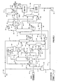
- FIG. 1 An exemplary known gas treatment configuration that employs the use of a physical solvent is depicted in prior art Figure 1 in which an absorber 203, a flash drum 205, a recycle compressor 206, exchanger 207, a solvent regenerator 208, a reboiler 209, a solvent pump 216, and a refrigerant chiller 217 are configured to remove hydrogen sulfide and contaminants from a feed gas (Further components of this plant include sulfur plant 213, hydrogenation and quench unit 214 and tail gas unit 215). It should be recognized that such plants are typically not selective in the removal of H 2 S and contaminants ( i.e ., co-absorption of CO 2 by the solvent is relatively high).
- the feed gas 1 comprises relatively large CO 2 quantities (e.g ., greater than 50%)
- co-absorption of CO 2 in such plants requires higher solvent circulation and higher energy consumption and also produces an acid gas rich in CO2 (typically 80%) that is an undesirable acid gas for the sulfur plants.
- the feed gas comprises relatively high concentrations of acid gas and other contaminants
- the capital and operating costs required by these processes are generally very high.
- post treatment of the treated gas from these units with additional processing equipment is required, due to the fact that elimination of contaminants is frequently below desirable levels.
- Such a unit is disclosed, for example, in US 4, 305, 733 .
- a tail gas unit is often used to control the sulfur emissions from the sulfur plant. Even if the emission is reduced to a very low ppm level, the total quantity of annual sulfur emissions (tons/year) in the vent stream is still relatively high, due to relatively large venting rates attributed to the large co-absorbed CO 2 in the treating process US 4,425,317 discloses returning a tail gas to a lower section of a prior H 2 S enrichment stage.
- the present invention is directed to methods with the features of claim 1 for treatment of a gas comprising relatively high levels of acid gases, hydrocarbons and other contaminants, wherein contemplated configurations and methods significantly reduce, if not even almost eliminate emissions of sulfurous components, heavy hydrocarbons, and/or other contaminants while providing a sulfur and contaminant-depleted dehydrated gas with a low hydrocarbon dew point suitable for pipeline sales. Further desirable features are set out in claims 2 to 3.
- gas comprising relatively high levels of acid gases and other contaminants can be treated in a process that significantly reduces, if not even almost eliminates emissions of sulfurous components, hydrocarbons, and/or other contaminants.
- Contemplated process will typically produce a dehydrated gas with a low hydrocarbon dewpoint that will meet pipeline sales gas specifications.
- contemplated configurations will produce a hydrogen sulfide rich and hydrocarbon depleted gas that can be efficiently processed in a sulfur plant, and the tail gas of the sulfur plant is (after hydrogenation and quenching) recycled back to the feed gas.
- the hydrocarbons separated and recovered from the feed gas in contemplated configurations are generally suitable for use as a liquid fuel after further processing.
- contemplated configurations and methods allow for feed gas processing of a contaminated feed gas in which all undesirable components (especially including heavy and light hydrocarbons, mercaptans, hydrogen sulfide, and carbon dioxide) are recycled to extinction, or removed and recovered as commercially valuable products.
- a four-step absorption process is employed in which a lean solvent (most preferably a solvent comprising dialkyl ethers of polyethylene glycols and water) selectively absorbs sulfurous components, hydrocarbons, and/or other contaminants.
- a cooling/absorption process may be included to trap undesirable hydrocarbons and contaminants (e.g., mercaptans or disulfides) in a hydrocarbon liquid that is then processed in another step to produce valuable products.
- feed gas stream 1 at ambient temperature and atmospheric pressure, is combined with the hydrogenation/quench gas stream 2 to form stream 3 that is compressed in feed compressor 101.
- Recycle stream 4 from the reboiled absorber 110 is fed to the interstage of compressor 101 and the total gas stream is compressed to a suitable pressure forming stream 5, typically at 1.4mPa to 2.8 mPa (200 to 400 psig) or as needed for the pipeline requirement.
- the feed gas composition may vary considerably, and that suitable feed gases include natural gas at various pressures, synthesis gas, landfill waste gases, and various refinery off-gases.
- the feed gas is a low pressure, low quality natural gas with a composition of about 30 to 70% CO 2 , 20 to 50% C 1 ; 2 to 5% H 2 S, 0.5 to 10% H 2 , 3 to 5% C 2 -C 5 , 0.5 to 2% C 6 -C 7 , 0.1 to 0.5 % C 8- C 9+ , 0.2 to 1% mercaptans, disulfides, COS and HCN contaminants, with the balance being inerts ( e.g., N 2 ).
- suitable feed gases may comprise water, and may even be saturated with water.
- the low quality feed gas stream has a feed rate of 100 MMscfd and is supplied at close to atmospheric pressure and ambient temperature, and is saturated with water.
- the four absorption steps are performed with lean solvent streams using lean solvent stream 6, 14, 25, and 45 respectively.
- solvent employed in contemplated absorbers aborber 103, 110 and 118
- numerous physical solvents and mixtures thereof are appropriate.
- exemplary solvents include propylene carbonate, tributyl phosphate, normal methyl pyrrolidone, and other various polyethylene glycol dialkyl ethers.
- suitable solvents may also include an enhanced tertiary amine or other solvent having similar behavior as a physical solvent.
- the solvent comprises a mixture of dimethyl ethers of polyethylene glycols and water.
- water at suitable concentrations in dimethyl ethers of polyethylene glycols will promote stripping and desorption of contaminants from the solvent.
- a specified and relatively small quantity of the lean solven is injected to the feed gas to trap heavy components, including C 9+ hydrocarbons and heavy mercaptans before the feed gas is further cooled and enters the absorber. Removal of the heavy contaminants from this first absorption prevents significant quantities of heavy hydrocarbons and contaminants from entering the second absorption step, thereby avoiding downstream heavy hydrocarbon condensation in the absorber. Furthermore, excessive heavy hydrocarbons in the absorber tends to cause foaming, which is also undesirable.
- the quantity of lean solvent required in this first absorption step is relative small, and will generally depend on the amount of heavy hydrocarbons in the feed.
- the quantity of lean solvent will be less than 10% of the total circulating solvent, and more typically about 2% to 5% of total solvent circulation. Furthermore, it should be recognized that the quantity of lean solvent can be adjusted as needed to remove the heavy hydrocarbons.
- lean solvent stream 6 at about 76 L/min. (20 gpm) is mixed with compressed feed gas stream 5 forming stream 7 that is cooled in exchanger 102 with treated gas stream 18 (the product gas), to cooled stream 8 at typically 16°C to 32°C (60°F to 90°F).
- the absorption efficiency is significantly enhanced with the chilling process in exchanger 102 resulting in substantially complete removal of heavy components (e.g. , C 9+ hydrocarbons), heavy mercaptans, and disulfides, as well as the majority ( i.e ., at least 75%, and more typically at least 90%) of water content.
- Exchanger 102 preferably uses the refrigeration content in the treated gas stream 18, thus requiting no external cooling and producing warmed product gas 46.
- optional and/or additional external refrigeration may also be included (e.g ., where the feed gas contains relatively large amounts of heavy components).
- the absorber 103 comprises two sections, wherein the lower section is employed for separating the heavy contaminants from the feed gas absorbed in the first step, while the upper section is employed for the second absorption step to remove lighter contaminants (e.g ., hydrogen sulfide, light mercaptans, light hydrocarbons).
- lighter contaminants e.g ., hydrogen sulfide, light mercaptans, light hydrocarbons.
- the heavy contaminants e.g ., hydrocarbons, mercaptans, disulfides, etc.
- solvent stream 10 that is further fractionated in regenerator 113.
- stream 10 can be separately processed in a regenerator (not shown) operating under vacuum pressure that may be required for fractionation and removal of the very heavy components.
- the absorber has an upper and a lower section
- the two sections are separated, most typically by a chimney tray 125. Therefore, flashed gas stream 9 will flow upwards from the lower section of the absorber through chimney tray 125 and enters the upper section of the column. There, the gas is brought into counter-current contact with a carbon dioxide saturated solvent stream 11 entering near the top of the absorber.
- the absorber typically comprises conventional trays or packing, which provides approximately 14 to 18 equilibrium stages of gas-liquid contact. Under these conditions, approximately 3,785 L/min to 4,542 L/min (000 to 1200 gpm) of lean solvent circulation are required to reduce the total sulfur content (H 2 S, Mercaptans and disulfides) of the natural gas to less than 4 ppmv.
- H 2 S Mercaptans and disulfides
- carbon dioxide saturated solvent and “solvent saturated with carbon dioxide” are used interchangeably herein and refer to a solvent that is saturated with at least 50%, more typically at least 80%, and most typically at least 90% carbon dioxide at a particular pressure and temperature as compared to 100% saturation with carbon dioxide at the particular pressure and temperature.
- selective absorption of hydrogen sulfide refers to a preferred absorption of hydrogen sulfide over absorption of carbon dioxide from a particular gas into a particular solvent.
- sulfur plant as used herein generally refers to all plant configurations in which hydrogen sulfide is converted to elemental sulfur (and other by products), and which will typically emit a tail gas comprising relatively low levels of sulfurous compounds.
- the absorber 103 produces an overheard stream 12, which is partially depleted of contaminants (i.e ., contains less contaminants than the stream entering the absorber), typically at -7°C to 4°C (20 to 40°F), and a rich solvent stream 13 from chimney tray 125, typically at 4°C to 16°C (40 to 60°F).
- the overhead stream 12 is mixed with a lean solvent 14 supplied from the solvent chiller 121 at -18°C to 4°C (0 to 40°F), at approximately 4,164 L/min to 4,921 L/min (100 to 1300 gpm) forming the vapor-solvent mixture of stream 15.
- this additional step of vapor-solvent contact will saturate the lean solvent stream 14 with carbon dioxide while removing the residual contaminant and sulfur compounds from the feed gas in overhead stream 12.
- Stream 15 is further cooled in exchanger 104 using external refrigeration that removes the heat of absorption generated by the absorption of carbon dioxide by the solvent, and the mixture is further chilled to typically -12°C to 4°C (10 to 40°F) forming stream 16. Consequently, it should be recognized that the low temperature of stream 16 will favor the vapor-solvent absorption equilibrium, which in turn will result in a higher loading of acid gas and contaminants in the solvent, thereby reducing the overall solvent circulation and energy consumption.
- the absorber overhead temperature will be higher than that of the lean solvent, as limited by the approach to equilibrium temperature in the absorber.
- solvent loading capacity is reduced at the higher temperature, a higher solvent circulation is necessary to meet the same product gas sulfur specification.
- Higher solvent flow is undesirable, as co-absorption of carbon dioxide will increase, consequently increasing the quantity of acid gases that needs to be processed in the sulfur plant.
- the chilled vapor solvent mixture of stream 16 is separated in separator 105 into a contaminant depleted vapor stream 18 (the clean product gas) and a carbon dioxide enriched liquid stream 17.
- Stream 17 is split into two streams, where about 25% is sent as stream 25 to the third absorption step in absorber 110, while the remaining 75%, as stream 43, is pumped using solvent plump 106 to the top of absorber 103 as stream 1.1 to contact the contaminated natural gas rising up the absorber.
- the refrigerant content of vapor stream 18, typically at -12°C to 4°C (10 to 40°F) is used to cool the feed gas stream 7 in exchanger 102.
- the treated gas exits the treating unit as stream 46 as the product gas.
- the contaminant laden solvent stream 13 is letdown in pressure in JT valve 107 to form stream 19, typically at 0.7 mPa to 1.4 mPa (100 to 200 psig).
- Stream 19 is then heated in exchanger 108 by lean solvent stream 28 to typically 116°C to 135°C (240 to 275°F), forming stream 20.
- most of the acid gas, and particularly carbon dioxide is desorbed.
- Stream 20 is separated in separator 109 into a vapor stream 24 and a flashed liquid stream 21.
- About 98% or more of the light hydrocarbons, such as methane, about 95% of carbon dioxide, and about 70 % of the hydrogen sulfide are desorbed in stream 24.
- the flashed liquid stream 21 containing the residual gas (mainly hydrogen sulfide and contaminants) is mixed with streams 10 and 50 to form stream 22 prior to being sent to regenerator 113 via JT valve 112 for further fractionation.
- the third absorption step is performed in a reboiled absorber 110 that concentrates hydrogen sulfide and contaminants in the rich solvent by rejecting its carbon dioxide content (e.g., by heating the rich solvent).
- the use of reboiler 111 is optional and is required only to produce an acid gas with a very high hydrogen sulfide concentration.
- Stream 24 enters near the bottom of reboiled absorber 110 and lean solvent stream 25, supplied from separator 105 in the second absorption step, enters near the top of the column.
- supplementary heating duty is required at reboiler, either hot oil or steam can be used as a heat source to maintain the desired bottom temperature.
- the third absorption step is used to reject over 95% of the carbon dioxide content of steam 24.
- the reboiled absorber 110 is typically designed with 8 to 12 equilibrium stages of vapor solvent contact. Conventional trays or packing can be used as the vapor solvent contact device.
- the required solvent rate of stream 25 is typically at 25% of the total circulation or as needed to reabsorb substantially all of the hydrogen sulfide and contaminants that are desorbed in stream 24 via heating by exchanger 108.
- the absorber overhead vapor stream 44 containing mostly carbon dioxide and methane and depleted of hydrogen sulfide and contaminants can be used for carbon dioxide production in stream 44A, and/or recycled back to the interstage of the feed compressor in stream 4.
- the recycling process maximizes the recovery of methane (typically greater than 98%, and more typically greater than 99.5%) and other valuable gases while eliminating a potential source of emission.
- the reboiled absorber overhead vapor 44 is a highly concentrated carbon dioxide stream that is substantially contaminant free (typically less than 0.1 vol%, more typically less than 0.05 vol%), and is suitable for use as a feedstock for chemical production (e.g., for urea fertilizer manufacturing, or soft drink industries).
- the residual contaminants level in this stream is very low and therefore, further purification to meet the product carbon dioxide specification requires minimal capital and operating costs.
- the highly concentrated carbon dioxide stream may be employed in enhanced oil recovery in the associated oil field production. It should still further be recognized that removal of the carbon dioxide rich stream 44A also reduces the recycle flow of stream 4 and further improves the heating value of the product gas (particularly when the product gas is required to meet the heating value or Wobbe Index specification of a sales gas).
- the reboiled absorber bottom stream 23, containing about 5% of the residual carbon dioxide is split into stream 45 and stream 50.
- Stream 45 is used as hydrogen sulfide-rich lean solvent (after reduction in pressure via JT valve 128) for absorption of hydrocarbons in the fourth absorption step in absorber 118.
- Stream 50 is combined with stream 21 from separator 109 and stream 10 from the first absorption step, forming stream 22.
- Stream 22 is letdown in pressure via valve 112 to about 0,2 mPa (25 psig) forming stream 26 and enters the top section of regenerator 113.
- Regenerator 113 is preferably a fractionation column, typically designed with 12 to 16 equilibrium stages of vapor solvent contact. Conventional trays or packing can be used as the vapor solvent contact device.
- the regenerator bottoms temperature is typically maintained at 141°C to 149°C (285 to 300°F) with application of heat with either a hot oil or steam as a heat source.
- the reboiler duty is about 8.8 mw to 11.8mw (30 to 40 MMBtu/h) or as required to produce a lean solvent with very low sulfur and mercaptans content (less than 5 mg/kg (ppm)) necessary for meeting the 4 ⁇ L/L (ppmv) total sulfur specification for sales gas.
- the regenerator produces a lean solvent stream 28 and an overhead gas stream 29.
- the heat content of lean solvent is recovered by preheating (partially regenerating) the rich solvent in exchanger 108.
- stream 28 is cooled to form stream 40 at typically 38°C to 44°C (100 to 120°F).
- the cooled solvent is further pumped to absorber pressure with pump 120.
- the pump discharge stream 41 is split into stream 6 and stream 42.
- Stream 6 is injected to the feed gas stream for heavy hydrocarbon and contaminant removal in the first absorption step.
- Stream 42 is cooled with, refrigeration in exchanger 121 to typically -18°C to 4°C (0 to 40°F), and is mixed with overhead vapor 12 from absorber 103 in the second absorption step.
- the presence of a large amount of water (steam) at the bottom of the regenerator will enhance stripping and removal of the heavy components. Therefore, a person of ordinary skill in the art will adjust the water content in the solvent (e.g., dimethyl ethers of polyethylene glycols) to promote and/or optimize stripping and desorption of the contaminants from the solvent. In addition to removal of contaminants in the regenerator, the leaner solvent.is very effective in contaminant absorption in the second absorption step to help meet the stringent product gas specification.
- the solvent e.g., dimethyl ethers of polyethylene glycols
- the regenerator overhead gas stream 29 is cooled with a cooling medium (e.g., cooling water followed by a refrigerant) in exchanger 115 to typically 4°C to 10°C (40 to 50°F), forming stream 30 that is further separated in a three phase separator 116 into a liquid stream 31, a vapor stream 32, a water stream 34 and a hydrocarbon stream 35.
- a cooling medium e.g., cooling water followed by a refrigerant
- exchanger 115 typically 4°C to 10°C (40 to 50°F)
- stream 30 that is further separated in a three phase separator 116 into a liquid stream 31, a vapor stream 32, a water stream 34 and a hydrocarbon stream 35.
- Liquid stream 31, typically comprising water saturated with solvent, hydrocarbons and contaminant is pumped by reflux pump 117 to the regenerator as stream 27.
- a portion of the water is delivered to the regenerator to maintain the water content of the solvent at a predetermined level.
- various feed gas streams
- the contaminants in stream 32 decrease with decreasing temperature, and the lower limit is governed by the water freeze out temperature of 0°C (32°F).
- the residual contaminant level, and in particular the lighter contaminants such as methyl mercaptans, benzene, toluene and xylene may still be present in significant quantity (even at about 4°C (40°F), the contaminants level can be as high as 1 to 2%).
- the presence of such high levels of contaminants will have negative impacts in the sulfur operation plant, and particularly includes high energy consumption and short catalyst life, and off specification sulfur product.
- a fourth absorption step using absorber 118 is used to further treat the acid gas stream 32.
- Lean solvent stream 46A employed in this step originates from the bottom of absorber 110 in the third absorption step via stream 45. This solvent stream is particularly advantageous in the absorption of residual contaminants since it is saturated with hydrogen sulfide. Use of solvent 46A will reject most of the hydrogen sulfide. from the solvent to the overhead stream 47 while absorbing most of the hydrocarbons and contaminants from the acid gas in stream 32.
- This fourth absorption step further improves the hydrogen sulfide concentration to the sulfur plant by as high as 10%.
- the concentration of hydrogen sulfide in stream 47 to the sulfur plant can be as high as 70%.
- the bottom stream 33 from absorber 118 is pumped by pump 119 as stream 36 to the upper section of the regenerator 113, which separates the contaminants and hydrocarbon liquid in the overhead drum 116 producing the raw hydrocarbon liquid stream 35.
- Water stream 34 containing minimal residual contaminants, is purged from separator 116 to the sour water stripper unit in order to maintain a water balance.
- Vapor streams 47 and 48 from absorber 118 and stripper 126, respectively, typically comprising 50 to 70% hydrogen sulfide, 30 to 50% carbon dioxide (and very low level residual hydrocarbon content) can be fed directly to a sulfur plant 122.
- Such gas composition is expected to allow the sulfur plant to operate in a stable and efficient mode, with minimum oxygen and fuel consumption, while converting virtually all the residual hydrocarbons and mercaptans and disulfides into inert products.
- the sulfur plant produces a sulfur product stream 37 and a tail gas stream 38.
- the tail gas stream 38 is sent to a hydrogenation and quench unit 123.
- the gas is hydrogenated over a catalyst bed that converts all sulfur oxides back to hydrogen sulfide.
- the converted gas is quenched with water, cooled and exits the quench gas unit as stream 39.
- contemplated configurations allow for economically treating a highly contaminated feed gas to meet pipeline specification, improved contaminant removal, reduced recycle flow rates, heating and cooling duties, and significantly reduced capital and operating costs associated with the use of suck a process.
- carbon dioxide content in the product gas can be tailored to meet the sales gas specification by diverting the carbon dioxide rich recycle stream to outside the unit for industrial usages.
- a low quality gas is treated in four absorption steps for removal of contaminants, including heavy hydrocarbons, mercaptans, disulfides and aromatics, and that a cooler /stripper step process is employed in the solvent regenerator to remove the contaminants in a liquid, which is stripped to produce a stabilized marketable liquid product.
- the hydrogen sulfide is concentrated in the fourth absorption step to produce an acid gas with a hydrogen sulfide content of greater that 60%.
- Such concentrated hydrogen sulfide streams may advantageously be converted to an inert form of sulfur.
- the contaminant depleted acid gas stream is a highly desirable feed gas to a sulfur plant as the contaminant depleted acid gas stream will avoid poisoning and deactivation of the catalyst in a Claus reactor in the sulfur plant and thus ensure an on-specification sulfur product.
- contemplated configurations and processes are particularly useful for selectively removing gas contaminants such as hydrogen sulfide, mercaptans, disulfides, aromatics and heavy hydrocarbons from natural gas, synthesis gas, landfill waste gas; or refinery off-gases
- gas contaminants such as hydrogen sulfide, mercaptans, disulfides, aromatics and heavy hydrocarbons from natural gas, synthesis gas, landfill waste gas; or refinery off-gases
- alternative contaminants including various sulfur compounds, carbonyl sulfide, cyanides, and other gas contaminants may also be removed from a variety of feed gases.
- contemplated configurations and processes can also be used to efficiently extract carbon dioxide to meet sales gas specification on the heating value and Wobbe Index.
- the extracted carbon dioxide which is highly concentrated and contaminant free, may be further purified and used for chemical production or enhanced oil recovery.
- Tail gas from a sulfur plant after hydrogenation and quenching.
- the so converted tail gas (mostly hydrogen sulfide and carbon dioxide) is recycled back to the suction of the feed gas compressor.
- off-gas from the third absorption step is also recycled back to the interstage of the feed gas compressor.
- Contemplated configurations and processes can be advantageously used to process and treat a contaminant waste gas stream while upgrading the low quality gas to a high quality dehydrated gas for a consumer pipeline.
- contemplated configurations and processes will recover the energy value of the hydrocarbon contents as a sellable hydrocarbon liquid and a sulfur product. Therefore, such configurations and processes recycle all or almost all of the waste gas streams and will generally not produce gaseous emissions that are normally encountered in currently known processing facilities.
- the inventors contemplate a gas treatment plant with a first absorber in which a lean solvent absorbs carbon dioxide, hydrogen sulfide, and a hydrocarbon.
- a second absorber fluidly coupled to the first absorber, wherein at least part of the hydrogen sulfide is separated from the carbon dioxide, and sulfur plant receives the hydrogen sulfide to produce a sulfur product and a tail gas, wherein at least part of the tail gas is hydrogenated and is recycled to the absorber.
- Such plants may advantageously include a regenerator that is fluidly coupled to the first and second absorber, wherein the regenerator produces an acid gas, and wherein at least part of the hydrocarbon is separated from the acid gas as a hydrocarbon liquid.
- a stripper may be included that receives at least part of the hydrocarbon liquid and in which residual sulfurous compounds are at least partially stripped from the hydrocarbon liquid (and are preferably fed to the sulfur plant).
- the second absorber is operated at a lower pressure and at a higher temperature than the first absorber such that the carbon dioxide is desorbed form the rich solvent and is recycled back to the first absorber. The so produced carbon dioxide may then be used for enhanced oil recovery or used as commercial product (after optional further purification).
- contemplated plants may include an absorber that receives (a) a feed gas comprising carbon dioxide and hydrogen sulfide and (b) a carbon dioxide saturated lean solvent, and that produces an overhead vapor comprising at least a portion of the carbon dioxide, wherein a lean solvent is combined with the overhead vapor and then cooled, to form a cooled carbon dioxide saturated lean solvent, thereby reducing the temperature rise in the absorber and hence increasing selective absorption of the hydrogen sulfide from the feed gas in the lean solvent.
- Such absorbers will preferably produce a bottom product that is reduced in pressure and heated to a (higher) temperature sufficient to desorb the carbon dioxide content from the bottom product, and it is further preferred that the hydrogen sulfide content in the separated carbon dioxide is further re-absorbed in a second absorber using a portion of the carbon dioxide saturated lean solvent.
- a gas treatment plant may include a solvent regenerator that receives from a plurality of absorbers a solvent comprising an acid gas and a hydrocarbon, and that produces an overhead vapor that is further cooled and separated forming an acid gas, water and hydrocarbon liquid.
- the hydrocarbon liquid is optionally fed to a stripper that fractionates the hydrocarbon liquid to produce a hydrogen sulfide depleted hydrocarbon product and a vapor comprising hydrogen sulfide that is fed to a sulfur plant.
- the acid gas is fed to an absorber in which a carbon dioxide depleted hydrogen sulfide rich solvent scrubs the acid gas, wherein the scrubbed acid gas is fed to the sulfur plant (which may produce a tail gas, wherein at least part of the tail gas is hydrogenated and recycled to at least one of the plurality of the absorbers).
- contemplated plants may include an absorber that receives from a solvent regenerator a vapor comprising hydrogen sulfide and a hydrocarbon, wherein the absorber further receives a carbon dioxide-depleted solvent comprising hydrogen sulfide, and wherein the absorber produces a hydrocarbon-depleted overhead vapor comprising hydrogen sulfide that is fed to a sulfur plant, and a hydrocarbonenriched bottom product that is recycled to the solvent regenerator.
- the carbon dioxide-depleted solvent is produced by another absorber that separates hydrogen sulfide from carbon dioxide using a carbon dioxide saturated lean solvent, and that a portion of the carbon dioxide-depleted solvent is fed to the solvent regenerator.
- the inventors contemplate a method of treating a gas in which in one step the gas is optionally contacted with a first portion of a lean solvent to absorb at least one of a heavy hydrocarbon and a heavy mercaptan from the gas into the first portion of the lean solvent.
- the gas is cooled and the cooled gas is contacted in an absorber with a second portion of the lean solvent to absorb at least one of a light hydrocarbon, a light mercaptan, and H 2 S into the second portion of the lean solvent, wherein the second portion of the lean solvent is saturated with carbon dioxide.
- the gas exiting the absorber is further contacted with a third portion of the lean solvent to saturate the third portion with carbon dioxide thereby forming a gas solvent mix, and the gas solvent mix is then cooled and separated thereby forming the second portion of the lean solvent that is saturated with carbon dioxide.
Landscapes
- Chemical & Material Sciences (AREA)
- Engineering & Computer Science (AREA)
- Chemical Kinetics & Catalysis (AREA)
- Oil, Petroleum & Natural Gas (AREA)
- Analytical Chemistry (AREA)
- General Chemical & Material Sciences (AREA)
- Organic Chemistry (AREA)
- Inorganic Chemistry (AREA)
- Environmental & Geological Engineering (AREA)
- Biomedical Technology (AREA)
- Health & Medical Sciences (AREA)
- Gas Separation By Absorption (AREA)
- Production Of Liquid Hydrocarbon Mixture For Refining Petroleum (AREA)
Abstract
Claims (3)
- Procédé de traitement d'un gaz (1) contenant du dioxyde de carbone et du sulfure d'hydrogène, pour fournir un gaz déshydraté appauvri en soufre et en contaminants (46) avec un point de rosée des hydrocarbures bas, adapté à la vente par pipeline, lequel procédé comprend :- mise en contact du gaz (1), avant que le gaz n'entre dans un absorbeur (103), avec une première portion (6) d'un solvant pauvre pour absorber au moins un parmi un hydrocarbure C9+, un éthyl mercaptan et des mercaptans plus lourds du gaz (1) dans la première portion (6) du solvant pauvre ;- refroidissement (102) du gaz mis en contact (7) avant que le gaz mis en contact (7) n'entre dans l'absorbeur (103) ;- mise en contact du gaz refroidi (8) dans un absorbeur (103) avec une partie (11) d'une deuxième portion (17) du solvant pauvre pour absorber au moins un parmi méthane, benzène, toluène, xylène, un méthyl mercaptan et H2S dans la partie (11) de la deuxième portion (17) du solvant pauvre, la deuxième portion (17) du solvant pauvre étant saturée en dioxyde de carbone de façon qu'à la pression et à la température particulière, la deuxième portion (17) du solvant pauvre soit saturée à au moins 50 % en dioxyde de carbone par rapport à une saturation à 100 % en dioxyde de carbone à la pression et à la température particulière ;- mise en contact d'une vapeur de tête (12) sortant de l'absorbeur (103) avec une troisième portion (14) du solvant pauvre pour saturer la troisième portion (14) en dioxyde de carbone et former ainsi un mélange gaz-solvant (15) ;- refroidissement (104) et séparation (105) du mélange gaz-solvant (15) de manière à former la deuxième portion (17) du solvant pauvre qui est saturée en dioxyde de carbone ; et- utilisation d'une autre partie (25) de la deuxième portion (17) du solvant pauvre qui est saturée en dioxyde de carbone dans un autre absorbeur (110) comme un solvant absorbant qui élimine le sulfure d'hydrogène d'une vapeur (24).
- Procédé selon la revendication 1, dans lequel l'autre absorbeur (110) fonctionne dans des conditions qui permettent le rejet du dioxyde de carbone de l'autre partie (25) de la deuxième portion (17) du solvant pauvre.
- Procédé selon la revendication 1 ou 2, dans lequel l'absorbeur (103) produit un produit de fond (13) qui est réduit en pression (107) et chauffé (108) à une température suffisante pour désorber le dioxyde de carbone du produit de fond (13) dans la vapeur (24) et dans lequel au moins une portion du sulfure d'hydrogène dans la vapeur (24) est absorbée dans l'autre absorbeur (110) utilisant l'autre partie (25) de la deuxième portion (17) du solvant pauvre qui est saturée en dioxyde de carbone.
Applications Claiming Priority (3)
| Application Number | Priority Date | Filing Date | Title |
|---|---|---|---|
| US43435802P | 2002-12-17 | 2002-12-17 | |
| US434358P | 2002-12-17 | ||
| PCT/US2003/004376 WO2004058384A1 (fr) | 2002-12-17 | 2003-02-12 | Agencements et procedes permettant d'eliminer des gaz acides et des impuretes avec une emission proche de zero |
Publications (3)
| Publication Number | Publication Date |
|---|---|
| EP1572324A1 EP1572324A1 (fr) | 2005-09-14 |
| EP1572324A4 EP1572324A4 (fr) | 2006-11-02 |
| EP1572324B1 true EP1572324B1 (fr) | 2012-08-15 |
Family
ID=32682033
Family Applications (1)
| Application Number | Title | Priority Date | Filing Date |
|---|---|---|---|
| EP03814002A Expired - Lifetime EP1572324B1 (fr) | 2002-12-17 | 2003-02-12 | Procede permettant d'eliminer des gaz acides et des impuretes avec une emission proche de zero |
Country Status (10)
| Country | Link |
|---|---|
| US (1) | US7597746B2 (fr) |
| EP (1) | EP1572324B1 (fr) |
| JP (1) | JP4942935B2 (fr) |
| CN (1) | CN100563789C (fr) |
| AU (1) | AU2003211033B2 (fr) |
| CA (1) | CA2503656C (fr) |
| EA (1) | EA010169B1 (fr) |
| ES (1) | ES2392712T3 (fr) |
| MX (1) | MXPA05006242A (fr) |
| WO (1) | WO2004058384A1 (fr) |
Families Citing this family (92)
| Publication number | Priority date | Publication date | Assignee | Title |
|---|---|---|---|---|
| GB0020491D0 (en) | 2000-08-18 | 2000-10-11 | Angiomed Ag | Stent with attached element and method of making such a stent |
| US20100095845A1 (en) * | 2003-03-04 | 2010-04-22 | Lg Chem, Ltd. | VENT GAS ABSORPTION SYSTEM AND METHOD FOR RECOVERY VOCs |
| RU2378040C2 (ru) | 2004-08-06 | 2010-01-10 | ИАйДжи, ИНК. | Тщательная очистка газообразных продуктов сгорания, включая удаление co2 |
| US7740691B2 (en) | 2006-01-10 | 2010-06-22 | Edwin W. Cash | Gas treating method and apparatus |
| GB0609841D0 (en) | 2006-05-17 | 2006-06-28 | Angiomed Ag | Bend-capable tubular prosthesis |
| GB0609911D0 (en) | 2006-05-18 | 2006-06-28 | Angiomed Ag | Bend-capable stent prosthesis |
| GB0613670D0 (en) | 2006-07-10 | 2006-08-16 | Angiomed Ag | Tubular metal prosthesis and method of making it |
| GB0616729D0 (en) | 2006-08-23 | 2006-10-04 | Angiomed Ag | Method of welding a component to a shape memory alloy workpiece |
| GB0616999D0 (en) | 2006-08-29 | 2006-10-04 | Angiomed Ag | Annular mesh |
| EA014983B1 (ru) * | 2006-08-31 | 2011-04-29 | Флуор Текнолоджиз Корпорейшн | Способ удаления серы из продуктового потока газовой скважины и установка для удаления серы из растворителя |
| WO2008028964A2 (fr) | 2006-09-07 | 2008-03-13 | Angiomed Gmbh & Co. Medizintechnik Kg | Implant hélicoïdal comportant des extrémités différentes |
| DE102006045379B4 (de) * | 2006-09-26 | 2008-07-31 | Lurgi Ag | Verfahren zur Herstellung von Wasserstoff |
| GB0622465D0 (en) | 2006-11-10 | 2006-12-20 | Angiomed Ag | Stent |
| GB0624419D0 (en) | 2006-12-06 | 2007-01-17 | Angiomed Ag | Stenting ring with marker |
| US20080168009A1 (en) * | 2007-01-08 | 2008-07-10 | Robert Paul Johnson | Business methods of renewable hydrocarbon-based fuel |
| GB0703379D0 (en) | 2007-02-21 | 2007-03-28 | Angiomed Ag | Stent with radiopaque marker |
| JP5709153B2 (ja) * | 2007-02-22 | 2015-04-30 | フルオー・テクノロジーズ・コーポレイシヨン | ガス化ストリームから二酸化炭素および水素を製造する構成および方法 |
| GB0706499D0 (en) | 2007-04-03 | 2007-05-09 | Angiomed Ag | Bendable stent |
| US8591631B2 (en) * | 2007-07-31 | 2013-11-26 | General Electric Company | Method and apparatus to produce synthetic gas |
| GB0717481D0 (en) | 2007-09-07 | 2007-10-17 | Angiomed Ag | Self-expansible stent with radiopaque markers |
| US8182577B2 (en) | 2007-10-22 | 2012-05-22 | Alstom Technology Ltd | Multi-stage CO2 removal system and method for processing a flue gas stream |
| US7862788B2 (en) | 2007-12-05 | 2011-01-04 | Alstom Technology Ltd | Promoter enhanced chilled ammonia based system and method for removal of CO2 from flue gas stream |
| JP4884527B2 (ja) * | 2008-01-23 | 2012-02-29 | 株式会社日立製作所 | 天然ガス液化プラント及び天然ガス液化プラント用動力供給設備 |
| DE102008031509A1 (de) | 2008-07-03 | 2010-01-07 | Linde Aktiengesellschaft | Verfahren zur Abtrennung von Schwefel aus einem Schwefel-enthaltenden Gas |
| US7846240B2 (en) | 2008-10-02 | 2010-12-07 | Alstom Technology Ltd | Chilled ammonia based CO2 capture system with water wash system |
| US8404027B2 (en) | 2008-11-04 | 2013-03-26 | Alstom Technology Ltd | Reabsorber for ammonia stripper offgas |
| US20100183491A1 (en) * | 2009-01-22 | 2010-07-22 | General Electric Company | Systems and methods for treating a stream comprising an undesirable emission gas |
| US20100219061A1 (en) * | 2009-03-02 | 2010-09-02 | Saudi Arabian Oil Company | Enhancement of acid gas enrichment process |
| JP5566448B2 (ja) | 2009-03-25 | 2014-08-06 | フルオー・テクノロジーズ・コーポレイシヨン | 高圧酸性ガスを除去するための改良された構成および方法 |
| US8292989B2 (en) | 2009-10-30 | 2012-10-23 | Alstom Technology Ltd | Gas stream processing |
| MX2011010404A (es) | 2009-04-20 | 2011-10-24 | Exxonmobil Upstream Res Co | Sistema criogenico para remocion de gases acidos de una corriente de gas de hidrocarburo y metodo para remover gases acidos. |
| US7811361B2 (en) * | 2009-06-30 | 2010-10-12 | Uop Llc | Process for a gas removal zone |
| US8790605B2 (en) | 2009-09-15 | 2014-07-29 | Alstom Technology Ltd | Method for removal of carbon dioxide from a process gas |
| US8784761B2 (en) | 2009-11-20 | 2014-07-22 | Alstom Technology Ltd | Single absorber vessel to capture CO2 |
| US8309047B2 (en) | 2009-09-15 | 2012-11-13 | Alstom Technology Ltd | Method and system for removal of carbon dioxide from a process gas |
| CA2774493C (fr) | 2009-09-18 | 2014-05-20 | Fluor Technologies Corporation | Configurations et procedes de retrait de co2 en grande quantite et a haute pression |
| US8518156B2 (en) | 2009-09-21 | 2013-08-27 | Alstom Technology Ltd | Method and system for regenerating a solution used in a wash vessel |
| EP2322265A1 (fr) | 2009-11-12 | 2011-05-18 | Alstom Technology Ltd | Système de traitement de gaz de fumée |
| US8293200B2 (en) | 2009-12-17 | 2012-10-23 | Alstom Technology Ltd | Desulfurization of, and removal of carbon dioxide from, gas mixtures |
| US9212061B2 (en) * | 2010-02-02 | 2015-12-15 | Bp Alternative Energy International Limited | Separation of gases |
| WO2011102830A1 (fr) | 2010-02-17 | 2011-08-25 | Fluor Technologies Corporation | Configurations et procédés d'élimination de gaz acide à pression élevée dans la production de gaz très pauvre en soufre |
| DE102010013279B3 (de) * | 2010-03-29 | 2011-07-28 | Uhde GmbH, 44141 | Verfahren und Vorrichtung zur Verarbeitung eines kohlendioxidreichen Sauergases in einem Claus-Prozess |
| US8562719B2 (en) * | 2010-07-06 | 2013-10-22 | General Electric Company | System for acid gas removal |
| US8728209B2 (en) | 2010-09-13 | 2014-05-20 | Alstom Technology Ltd | Method and system for reducing energy requirements of a CO2 capture system |
| US8491712B2 (en) * | 2010-09-13 | 2013-07-23 | General Electric Company | Dehydration systems and methods for removing water from a gas |
| US8623307B2 (en) | 2010-09-14 | 2014-01-07 | Alstom Technology Ltd. | Process gas treatment system |
| US20120152120A1 (en) * | 2010-12-15 | 2012-06-21 | Uop Llc | Production of carbon dioxide from synthesis gas |
| US10451344B2 (en) | 2010-12-23 | 2019-10-22 | Fluor Technologies Corporation | Ethane recovery and ethane rejection methods and configurations |
| US8329128B2 (en) | 2011-02-01 | 2012-12-11 | Alstom Technology Ltd | Gas treatment process and system |
| US9028784B2 (en) | 2011-02-15 | 2015-05-12 | Alstom Technology Ltd | Process and system for cleaning a gas stream |
| DE102011053120A1 (de) * | 2011-08-30 | 2013-02-28 | Thyssenkrupp Uhde Gmbh | Verfahren und Anlage zur Entfernung von Kohlendioxid aus Rauchgasen |
| US9162177B2 (en) | 2012-01-25 | 2015-10-20 | Alstom Technology Ltd | Ammonia capturing by CO2 product liquid in water wash liquid |
| CA2867287C (fr) | 2012-03-21 | 2019-06-11 | Exxonmobil Upstream Research Company | Separation de dioxyde de carbone et d'ethane presents dans un courant melange |
| US8945292B2 (en) * | 2012-03-23 | 2015-02-03 | General Electric Company | System for recovering acid gases from a gas stream |
| US8864879B2 (en) | 2012-03-30 | 2014-10-21 | Jalal Askander | System for recovery of ammonia from lean solution in a chilled ammonia process utilizing residual flue gas |
| JP5972696B2 (ja) * | 2012-07-20 | 2016-08-17 | 三菱重工業株式会社 | Co2回収システム |
| US9671162B2 (en) | 2012-10-24 | 2017-06-06 | Fluor Technologies Corporation | Integration methods of gas processing plant and nitrogen rejection unit for high nitrogen feed gases |
| US9447996B2 (en) | 2013-01-15 | 2016-09-20 | General Electric Technology Gmbh | Carbon dioxide removal system using absorption refrigeration |
| US20140250887A1 (en) * | 2013-03-05 | 2014-09-11 | Mitsubishi Heavy Industries, Ltd. | Power generation system making use of low grade coal |
| AU2014357665B2 (en) | 2013-12-06 | 2017-06-22 | Exxonmobil Upstream Research Company | Method and device for separating a feed stream using radiation detectors |
| WO2015084499A2 (fr) | 2013-12-06 | 2015-06-11 | Exxonmobil Upstream Research Company | Procédé et système permettant de modifier un niveau de liquide pendant des opérations de démarrage |
| US9874395B2 (en) | 2013-12-06 | 2018-01-23 | Exxonmobil Upstream Research Company | Method and system for preventing accumulation of solids in a distillation tower |
| WO2015084498A2 (fr) | 2013-12-06 | 2015-06-11 | Exxonmobil Upstream Research Company | Procédé et système permettant de séparer un courant d'alimentation avec un mécanisme de distribution de courant d'alimentation |
| US9562719B2 (en) | 2013-12-06 | 2017-02-07 | Exxonmobil Upstream Research Company | Method of removing solids by modifying a liquid level in a distillation tower |
| WO2015084495A2 (fr) | 2013-12-06 | 2015-06-11 | Exxonmobil Upstream Research Company | Procédé et système de maintien d'un niveau de liquide dans une tour de distillation |
| CN105723171B (zh) | 2013-12-06 | 2018-06-05 | 埃克森美孚上游研究公司 | 采用加热设施使固体粘合不稳定和/或防止固体粘合的分离烃和污染物的方法和装置 |
| CN105722572B (zh) | 2013-12-06 | 2017-08-22 | 埃克森美孚上游研究公司 | 用喷射组件分离烃和杂质的方法和装置 |
| CA2925404C (fr) | 2013-12-06 | 2018-02-06 | Exxonmobil Upstream Research Company | Procede et systeme de deshydratation d'un flux d'alimentation traite dans une tour de distillation |
| WO2015089446A1 (fr) | 2013-12-12 | 2015-06-18 | Fluor Technologies Corporation | Configurations et procédés pour un retrait de co2 flexible |
| US8986640B1 (en) | 2014-01-07 | 2015-03-24 | Alstom Technology Ltd | System and method for recovering ammonia from a chilled ammonia process |
| RU2576738C9 (ru) * | 2014-11-14 | 2016-05-20 | Общество с ограниченной ответственностью "ЭНГО Инжиниринг" | Способ переработки природного газа и устройство для его осуществления |
| EP3256550A4 (fr) | 2015-02-09 | 2018-08-29 | Fluor Technologies Corporation | Procédés et configuration d'un processus de récupération de liquides de gaz naturel pour un gaz d'alimentation riche basse pression |
| MX2017008683A (es) | 2015-02-27 | 2017-10-11 | Exxonmobil Upstream Res Co | Reduccion de carga de refrigeracion y deshidratacion para una corriente de alimentacion que entra a un proceso de destilacion criogenica. |
| US9682343B2 (en) * | 2015-04-09 | 2017-06-20 | Uop Llc | Sour syngas treatment apparatuses and processes for treating sour syngas comprising sulfur components and carbon dioxide |
| US10365037B2 (en) | 2015-09-18 | 2019-07-30 | Exxonmobil Upstream Research Company | Heating component to reduce solidification in a cryogenic distillation system |
| US11255603B2 (en) | 2015-09-24 | 2022-02-22 | Exxonmobil Upstream Research Company | Treatment plant for hydrocarbon gas having variable contaminant levels |
| AR107033A1 (es) * | 2015-12-09 | 2018-03-14 | Basf Se | Proceso y planta para enriquecimiento de gas ácido |
| US10006701B2 (en) | 2016-01-05 | 2018-06-26 | Fluor Technologies Corporation | Ethane recovery or ethane rejection operation |
| WO2017172321A1 (fr) | 2016-03-30 | 2017-10-05 | Exxonmobil Upstream Research Company | Fluide de réservoir auto-sourcé pour la récupération assistée de pétrole |
| EA037511B1 (ru) * | 2016-04-27 | 2021-04-06 | ДАУ ГЛОБАЛ ТЕКНОЛОДЖИЗ ЭлЭлСи | Способ селективного удаления кислых газов из потоков текучей среды с использованием смеси гибридного растворителя |
| US10330382B2 (en) | 2016-05-18 | 2019-06-25 | Fluor Technologies Corporation | Systems and methods for LNG production with propane and ethane recovery |
| WO2018013099A1 (fr) | 2016-07-13 | 2018-01-18 | Fluor Technologies Corporation | Élimination d'hydrocarbures lourds à partir d'un gaz pauvre pour liquéfaction de gnl |
| US11725879B2 (en) | 2016-09-09 | 2023-08-15 | Fluor Technologies Corporation | Methods and configuration for retrofitting NGL plant for high ethane recovery |
| WO2018147883A1 (fr) | 2017-02-09 | 2018-08-16 | Fluor Technologies Corporation | Absorption en deux étapes pour élimination de gaz acide et de mercaptan |
| CN106988741A (zh) * | 2017-02-22 | 2017-07-28 | 中国石油化工股份有限公司 | 一种含硫气井试气试采装置 |
| JP6906761B2 (ja) * | 2017-05-01 | 2021-07-21 | 株式会社神戸製鋼所 | ガス処理方法及びガス処理装置 |
| WO2019078892A1 (fr) | 2017-10-20 | 2019-04-25 | Fluor Technologies Corporation | Mise en œuvre par phases d'usines de récupération de liquides de gaz naturels |
| JP6906766B2 (ja) * | 2017-11-30 | 2021-07-21 | 株式会社神戸製鋼所 | ガス処理方法及びガス処理装置 |
| CA3099630A1 (fr) * | 2018-05-07 | 2019-11-14 | 8 Rivers Capital, Llc | Separation des matieres soufrees |
| WO2020005553A1 (fr) | 2018-06-29 | 2020-01-02 | Exxonmobil Upstream Research Company (Emhc-N1.4A.607) | Mélange et intégration de chaleur de liquides de plateau de fusion dans une tour de distillation cryogénique |
| WO2020005552A1 (fr) | 2018-06-29 | 2020-01-02 | Exxonmobil Upstream Research Company | Plateau hybride pour introduire un flux d'alimentation en à faible teneur en co2 dans une tour de distillation |
| US10662061B1 (en) * | 2019-08-20 | 2020-05-26 | Saudi Arabian Oil Company | Two-stage adsorption process for Claus tail gas treatment |
Citations (3)
| Publication number | Priority date | Publication date | Assignee | Title |
|---|---|---|---|---|
| EP0375077A2 (fr) * | 1988-12-23 | 1990-06-27 | Shell Internationale Researchmaatschappij B.V. | Séparation de l'acide sulfhydrique dans des mélanges gazeux |
| WO1993010883A1 (fr) * | 1991-11-27 | 1993-06-10 | Exxon Research And Engineering Company | Procede d'enrichissement de gaz acide pauvre a l'aide d'amines entravees selectives |
| US5240476A (en) * | 1988-11-03 | 1993-08-31 | Air Products And Chemicals, Inc. | Process for sulfur removal and recovery from a power generation plant using physical solvent |
Family Cites Families (11)
| Publication number | Priority date | Publication date | Assignee | Title |
|---|---|---|---|---|
| US3877893A (en) * | 1973-05-10 | 1975-04-15 | Allied Chem | Absorption and separation of normally liquid gas contaminants |
| US3989811A (en) * | 1975-01-30 | 1976-11-02 | Shell Oil Company | Process for recovering sulfur from fuel gases containing hydrogen sulfide, carbon dioxide, and carbonyl sulfide |
| DE2551717C3 (de) * | 1975-11-18 | 1980-11-13 | Basf Ag, 6700 Ludwigshafen | und ggf. COS aus Gasen |
| US4080424A (en) * | 1976-02-11 | 1978-03-21 | Institute Of Gas Technology | Process for acid gas removal from gaseous mixtures |
| US4138230A (en) * | 1977-07-05 | 1979-02-06 | Uop Inc. | Dual pressure absorption process |
| DE2909335A1 (de) * | 1979-03-09 | 1980-09-18 | Linde Ag | Verfahren und vorrichtung zur zerlegung von erdgas |
| US4242108A (en) * | 1979-11-07 | 1980-12-30 | Air Products And Chemicals, Inc. | Hydrogen sulfide concentrator for acid gas removal systems |
| NL8001886A (nl) * | 1980-03-31 | 1981-11-02 | Shell Int Research | Werkwijze voor het verwijderen van zure gassen uit een in hoofdzaak uit methaan bestaand gasmengsel. |
| DE3047830A1 (de) * | 1980-12-18 | 1982-07-15 | Linde Ag, 6200 Wiesbaden | Verfahren zum reinigen eines gasstromes |
| FR2636857B1 (fr) * | 1988-09-26 | 1990-12-14 | Inst Francais Du Petrole | Procede de deshydratation, de desacidification et de separation d'un condensat d'un gaz naturel |
| FR2722110B1 (fr) * | 1994-07-08 | 1996-08-30 | Inst Francais Du Petrole | Procede de desacidification d'un gaz pour production de gaz acides concentres |
-
2003
- 2003-02-12 CA CA2503656A patent/CA2503656C/fr not_active Expired - Fee Related
- 2003-02-12 AU AU2003211033A patent/AU2003211033B2/en not_active Ceased
- 2003-02-12 ES ES03814002T patent/ES2392712T3/es not_active Expired - Lifetime
- 2003-02-12 EP EP03814002A patent/EP1572324B1/fr not_active Expired - Lifetime
- 2003-02-12 JP JP2004563175A patent/JP4942935B2/ja not_active Expired - Fee Related
- 2003-02-12 MX MXPA05006242A patent/MXPA05006242A/es active IP Right Grant
- 2003-02-12 CN CNB038256509A patent/CN100563789C/zh not_active Expired - Fee Related
- 2003-02-12 US US10/532,262 patent/US7597746B2/en not_active Expired - Fee Related
- 2003-02-12 EA EA200500983A patent/EA010169B1/ru not_active IP Right Cessation
- 2003-02-12 WO PCT/US2003/004376 patent/WO2004058384A1/fr active Application Filing
Patent Citations (3)
| Publication number | Priority date | Publication date | Assignee | Title |
|---|---|---|---|---|
| US5240476A (en) * | 1988-11-03 | 1993-08-31 | Air Products And Chemicals, Inc. | Process for sulfur removal and recovery from a power generation plant using physical solvent |
| EP0375077A2 (fr) * | 1988-12-23 | 1990-06-27 | Shell Internationale Researchmaatschappij B.V. | Séparation de l'acide sulfhydrique dans des mélanges gazeux |
| WO1993010883A1 (fr) * | 1991-11-27 | 1993-06-10 | Exxon Research And Engineering Company | Procede d'enrichissement de gaz acide pauvre a l'aide d'amines entravees selectives |
Also Published As
| Publication number | Publication date |
|---|---|
| US7597746B2 (en) | 2009-10-06 |
| MXPA05006242A (es) | 2005-08-19 |
| JP4942935B2 (ja) | 2012-05-30 |
| EA010169B1 (ru) | 2008-06-30 |
| AU2003211033B2 (en) | 2008-10-09 |
| EA200500983A1 (ru) | 2005-12-29 |
| JP2006509628A (ja) | 2006-03-23 |
| EP1572324A1 (fr) | 2005-09-14 |
| US20060150812A1 (en) | 2006-07-13 |
| CN1713948A (zh) | 2005-12-28 |
| CN100563789C (zh) | 2009-12-02 |
| AU2003211033A1 (en) | 2004-07-22 |
| CA2503656C (fr) | 2010-10-05 |
| WO2004058384A1 (fr) | 2004-07-15 |
| EP1572324A4 (fr) | 2006-11-02 |
| CA2503656A1 (fr) | 2004-07-15 |
| ES2392712T3 (es) | 2012-12-13 |
Similar Documents
| Publication | Publication Date | Title |
|---|---|---|
| EP1572324B1 (fr) | Procede permettant d'eliminer des gaz acides et des impuretes avec une emission proche de zero | |
| US7635408B2 (en) | Methods and configurations for acid gas enrichment | |
| US7662215B2 (en) | Methods for removing sulfur-containing compounds | |
| CA2605649C (fr) | Dispositifs et procedes d'absorption de gaz acides et de regeneration de solvants | |
| US7803271B2 (en) | Method of extracting the hydrogen sulfide contained in a hydrocarbon gas | |
| US20170114295A1 (en) | Configurations And Methods For Processing High Pressure Acid Gases With Zero Emissions | |
| US4483834A (en) | Gas treating process for selective H2 S removal | |
| US11724229B2 (en) | Process and plant for removing disruptive components from raw synthesis gas | |
| AU2011234876A1 (en) | Process for workup of a carbon dioxide-rich gas to be freed of sulfur components | |
| US5716587A (en) | Apparatus for removal of contaminates from a gas stream | |
| CN1795039A (zh) | 选择性去除原煤气中硫化氢和二氧化碳的方法 | |
| CA2162575A1 (fr) | Methode de controle des emanations de deshydrateurs au glycol | |
| US4460395A (en) | Method and apparatus for producing food grade carbon dioxide | |
| US12076690B2 (en) | Process and plant for purifying crude synthesis gas | |
| EP0052482B1 (fr) | Procédé pour le traitement d'un courant de gaz industriels | |
| US20200360855A1 (en) | Process of improved sulfur capture from a syngas mixture | |
| EP3808431A1 (fr) | Procédé et installation de désacidification d'un courant fluidique comprenant des composés de soufre, y compris des composés organiques de soufre | |
| Wood et al. | Gas treating process for selective H 2 S removal |
Legal Events
| Date | Code | Title | Description |
|---|---|---|---|
| PUAI | Public reference made under article 153(3) epc to a published international application that has entered the european phase |
Free format text: ORIGINAL CODE: 0009012 |
|
| 17P | Request for examination filed |
Effective date: 20050502 |
|
| AK | Designated contracting states |
Kind code of ref document: A1 Designated state(s): AT BE BG CH CY CZ DE DK EE ES FI FR GB GR HU IE IT LI LU MC NL PT SE SI SK TR |
|
| AX | Request for extension of the european patent |
Extension state: AL LT LV MK RO |
|
| DAX | Request for extension of the european patent (deleted) | ||
| RAP1 | Party data changed (applicant data changed or rights of an application transferred) |
Owner name: FLUOR CORPORATION |
|
| A4 | Supplementary search report drawn up and despatched |
Effective date: 20060928 |
|
| 17Q | First examination report despatched |
Effective date: 20091218 |
|
| GRAP | Despatch of communication of intention to grant a patent |
Free format text: ORIGINAL CODE: EPIDOSNIGR1 |
|
| RTI1 | Title (correction) |
Free format text: METHOD FOR ACID GAS AND CONTAMINANT REMOVAL WITH NEAR ZERO EMISSION |
|
| GRAS | Grant fee paid |
Free format text: ORIGINAL CODE: EPIDOSNIGR3 |
|
| GRAA | (expected) grant |
Free format text: ORIGINAL CODE: 0009210 |
|
| AK | Designated contracting states |
Kind code of ref document: B1 Designated state(s): AT BE BG CH CY CZ DE DK EE ES FI FR GB GR HU IE IT LI LU MC NL PT SE SI SK TR |
|
| REG | Reference to a national code |
Ref country code: GB Ref legal event code: FG4D Ref country code: CH Ref legal event code: EP Ref country code: AT Ref legal event code: REF Ref document number: 570504 Country of ref document: AT Kind code of ref document: T Effective date: 20120815 |
|
| REG | Reference to a national code |
Ref country code: IE Ref legal event code: FG4D |
|
| REG | Reference to a national code |
Ref country code: DE Ref legal event code: R096 Ref document number: 60341869 Country of ref document: DE Effective date: 20121011 |
|
| REG | Reference to a national code |
Ref country code: NL Ref legal event code: T3 |
|
| REG | Reference to a national code |
Ref country code: ES Ref legal event code: FG2A Ref document number: 2392712 Country of ref document: ES Kind code of ref document: T3 Effective date: 20121213 |
|
| REG | Reference to a national code |
Ref country code: AT Ref legal event code: MK05 Ref document number: 570504 Country of ref document: AT Kind code of ref document: T Effective date: 20120815 |
|
| PG25 | Lapsed in a contracting state [announced via postgrant information from national office to epo] |
Ref country code: CY Free format text: LAPSE BECAUSE OF FAILURE TO SUBMIT A TRANSLATION OF THE DESCRIPTION OR TO PAY THE FEE WITHIN THE PRESCRIBED TIME-LIMIT Effective date: 20120815 Ref country code: AT Free format text: LAPSE BECAUSE OF FAILURE TO SUBMIT A TRANSLATION OF THE DESCRIPTION OR TO PAY THE FEE WITHIN THE PRESCRIBED TIME-LIMIT Effective date: 20120815 Ref country code: FI Free format text: LAPSE BECAUSE OF FAILURE TO SUBMIT A TRANSLATION OF THE DESCRIPTION OR TO PAY THE FEE WITHIN THE PRESCRIBED TIME-LIMIT Effective date: 20120815 |
|
| PG25 | Lapsed in a contracting state [announced via postgrant information from national office to epo] |
Ref country code: BE Free format text: LAPSE BECAUSE OF FAILURE TO SUBMIT A TRANSLATION OF THE DESCRIPTION OR TO PAY THE FEE WITHIN THE PRESCRIBED TIME-LIMIT Effective date: 20120815 Ref country code: SE Free format text: LAPSE BECAUSE OF FAILURE TO SUBMIT A TRANSLATION OF THE DESCRIPTION OR TO PAY THE FEE WITHIN THE PRESCRIBED TIME-LIMIT Effective date: 20120815 Ref country code: PT Free format text: LAPSE BECAUSE OF FAILURE TO SUBMIT A TRANSLATION OF THE DESCRIPTION OR TO PAY THE FEE WITHIN THE PRESCRIBED TIME-LIMIT Effective date: 20121217 Ref country code: SI Free format text: LAPSE BECAUSE OF FAILURE TO SUBMIT A TRANSLATION OF THE DESCRIPTION OR TO PAY THE FEE WITHIN THE PRESCRIBED TIME-LIMIT Effective date: 20120815 Ref country code: GR Free format text: LAPSE BECAUSE OF FAILURE TO SUBMIT A TRANSLATION OF THE DESCRIPTION OR TO PAY THE FEE WITHIN THE PRESCRIBED TIME-LIMIT Effective date: 20121116 |
|
| PG25 | Lapsed in a contracting state [announced via postgrant information from national office to epo] |
Ref country code: DK Free format text: LAPSE BECAUSE OF FAILURE TO SUBMIT A TRANSLATION OF THE DESCRIPTION OR TO PAY THE FEE WITHIN THE PRESCRIBED TIME-LIMIT Effective date: 20120815 Ref country code: EE Free format text: LAPSE BECAUSE OF FAILURE TO SUBMIT A TRANSLATION OF THE DESCRIPTION OR TO PAY THE FEE WITHIN THE PRESCRIBED TIME-LIMIT Effective date: 20120815 Ref country code: CZ Free format text: LAPSE BECAUSE OF FAILURE TO SUBMIT A TRANSLATION OF THE DESCRIPTION OR TO PAY THE FEE WITHIN THE PRESCRIBED TIME-LIMIT Effective date: 20120815 |
|
| PGFP | Annual fee paid to national office [announced via postgrant information from national office to epo] |
Ref country code: DE Payment date: 20130227 Year of fee payment: 11 Ref country code: FR Payment date: 20130311 Year of fee payment: 11 Ref country code: ES Payment date: 20130226 Year of fee payment: 11 |
|
| PG25 | Lapsed in a contracting state [announced via postgrant information from national office to epo] |
Ref country code: SK Free format text: LAPSE BECAUSE OF FAILURE TO SUBMIT A TRANSLATION OF THE DESCRIPTION OR TO PAY THE FEE WITHIN THE PRESCRIBED TIME-LIMIT Effective date: 20120815 |
|
| PGFP | Annual fee paid to national office [announced via postgrant information from national office to epo] |
Ref country code: NL Payment date: 20130224 Year of fee payment: 11 |
|
| PLBE | No opposition filed within time limit |
Free format text: ORIGINAL CODE: 0009261 |
|
| STAA | Information on the status of an ep patent application or granted ep patent |
Free format text: STATUS: NO OPPOSITION FILED WITHIN TIME LIMIT |
|
| 26N | No opposition filed |
Effective date: 20130516 |
|
| PG25 | Lapsed in a contracting state [announced via postgrant information from national office to epo] |
Ref country code: BG Free format text: LAPSE BECAUSE OF FAILURE TO SUBMIT A TRANSLATION OF THE DESCRIPTION OR TO PAY THE FEE WITHIN THE PRESCRIBED TIME-LIMIT Effective date: 20121115 |
|
| REG | Reference to a national code |
Ref country code: DE Ref legal event code: R097 Ref document number: 60341869 Country of ref document: DE Effective date: 20130516 |
|
| PG25 | Lapsed in a contracting state [announced via postgrant information from national office to epo] |
Ref country code: MC Free format text: LAPSE BECAUSE OF NON-PAYMENT OF DUE FEES Effective date: 20130228 |
|
| REG | Reference to a national code |
Ref country code: CH Ref legal event code: PL |
|
| GBPC | Gb: european patent ceased through non-payment of renewal fee |
Effective date: 20130212 |
|
| PG25 | Lapsed in a contracting state [announced via postgrant information from national office to epo] |
Ref country code: CH Free format text: LAPSE BECAUSE OF NON-PAYMENT OF DUE FEES Effective date: 20130228 Ref country code: LI Free format text: LAPSE BECAUSE OF NON-PAYMENT OF DUE FEES Effective date: 20130228 |
|
| REG | Reference to a national code |
Ref country code: IE Ref legal event code: MM4A |
|
| PG25 | Lapsed in a contracting state [announced via postgrant information from national office to epo] |
Ref country code: GB Free format text: LAPSE BECAUSE OF NON-PAYMENT OF DUE FEES Effective date: 20130212 Ref country code: IE Free format text: LAPSE BECAUSE OF NON-PAYMENT OF DUE FEES Effective date: 20130212 |
|
| REG | Reference to a national code |
Ref country code: DE Ref legal event code: R119 Ref document number: 60341869 Country of ref document: DE |
|
| REG | Reference to a national code |
Ref country code: NL Ref legal event code: V1 Effective date: 20140901 |
|
| PG25 | Lapsed in a contracting state [announced via postgrant information from national office to epo] |
Ref country code: NL Free format text: LAPSE BECAUSE OF NON-PAYMENT OF DUE FEES Effective date: 20140901 |
|
| REG | Reference to a national code |
Ref country code: FR Ref legal event code: ST Effective date: 20141031 |
|
| REG | Reference to a national code |
Ref country code: DE Ref legal event code: R119 Ref document number: 60341869 Country of ref document: DE Effective date: 20140902 |
|
| PG25 | Lapsed in a contracting state [announced via postgrant information from national office to epo] |
Ref country code: DE Free format text: LAPSE BECAUSE OF NON-PAYMENT OF DUE FEES Effective date: 20140902 Ref country code: FR Free format text: LAPSE BECAUSE OF NON-PAYMENT OF DUE FEES Effective date: 20140228 |
|
| REG | Reference to a national code |
Ref country code: ES Ref legal event code: FD2A Effective date: 20150327 |
|
| PG25 | Lapsed in a contracting state [announced via postgrant information from national office to epo] |
Ref country code: ES Free format text: LAPSE BECAUSE OF NON-PAYMENT OF DUE FEES Effective date: 20140213 |
|
| PG25 | Lapsed in a contracting state [announced via postgrant information from national office to epo] |
Ref country code: TR Free format text: LAPSE BECAUSE OF FAILURE TO SUBMIT A TRANSLATION OF THE DESCRIPTION OR TO PAY THE FEE WITHIN THE PRESCRIBED TIME-LIMIT Effective date: 20120815 |
|
| PG25 | Lapsed in a contracting state [announced via postgrant information from national office to epo] |
Ref country code: LU Free format text: LAPSE BECAUSE OF NON-PAYMENT OF DUE FEES Effective date: 20130212 Ref country code: HU Free format text: LAPSE BECAUSE OF FAILURE TO SUBMIT A TRANSLATION OF THE DESCRIPTION OR TO PAY THE FEE WITHIN THE PRESCRIBED TIME-LIMIT; INVALID AB INITIO Effective date: 20030212 |
|
| PG25 | Lapsed in a contracting state [announced via postgrant information from national office to epo] |
Ref country code: IT Free format text: LAPSE BECAUSE OF NON-PAYMENT OF DUE FEES Effective date: 20140212 |