EP3808431A1 - Procédé et installation de désacidification d'un courant fluidique comprenant des composés de soufre, y compris des composés organiques de soufre - Google Patents
Procédé et installation de désacidification d'un courant fluidique comprenant des composés de soufre, y compris des composés organiques de soufre Download PDFInfo
- Publication number
- EP3808431A1 EP3808431A1 EP20192531.0A EP20192531A EP3808431A1 EP 3808431 A1 EP3808431 A1 EP 3808431A1 EP 20192531 A EP20192531 A EP 20192531A EP 3808431 A1 EP3808431 A1 EP 3808431A1
- Authority
- EP
- European Patent Office
- Prior art keywords
- sulfur compounds
- organic sulfur
- absorbent liquid
- fluid stream
- offgas
- Prior art date
- Legal status (The legal status is an assumption and is not a legal conclusion. Google has not performed a legal analysis and makes no representation as to the accuracy of the status listed.)
- Withdrawn
Links
Images

Classifications
-
- B—PERFORMING OPERATIONS; TRANSPORTING
- B01—PHYSICAL OR CHEMICAL PROCESSES OR APPARATUS IN GENERAL
- B01D—SEPARATION
- B01D53/00—Separation of gases or vapours; Recovering vapours of volatile solvents from gases; Chemical or biological purification of waste gases, e.g. engine exhaust gases, smoke, fumes, flue gases, aerosols
- B01D53/02—Separation of gases or vapours; Recovering vapours of volatile solvents from gases; Chemical or biological purification of waste gases, e.g. engine exhaust gases, smoke, fumes, flue gases, aerosols by adsorption, e.g. preparative gas chromatography
- B01D53/04—Separation of gases or vapours; Recovering vapours of volatile solvents from gases; Chemical or biological purification of waste gases, e.g. engine exhaust gases, smoke, fumes, flue gases, aerosols by adsorption, e.g. preparative gas chromatography with stationary adsorbents
- B01D53/0407—Constructional details of adsorbing systems
- B01D53/0423—Beds in columns
-
- B—PERFORMING OPERATIONS; TRANSPORTING
- B01—PHYSICAL OR CHEMICAL PROCESSES OR APPARATUS IN GENERAL
- B01D—SEPARATION
- B01D53/00—Separation of gases or vapours; Recovering vapours of volatile solvents from gases; Chemical or biological purification of waste gases, e.g. engine exhaust gases, smoke, fumes, flue gases, aerosols
- B01D53/02—Separation of gases or vapours; Recovering vapours of volatile solvents from gases; Chemical or biological purification of waste gases, e.g. engine exhaust gases, smoke, fumes, flue gases, aerosols by adsorption, e.g. preparative gas chromatography
- B01D53/04—Separation of gases or vapours; Recovering vapours of volatile solvents from gases; Chemical or biological purification of waste gases, e.g. engine exhaust gases, smoke, fumes, flue gases, aerosols by adsorption, e.g. preparative gas chromatography with stationary adsorbents
- B01D53/0462—Temperature swing adsorption
-
- B—PERFORMING OPERATIONS; TRANSPORTING
- B01—PHYSICAL OR CHEMICAL PROCESSES OR APPARATUS IN GENERAL
- B01D—SEPARATION
- B01D53/00—Separation of gases or vapours; Recovering vapours of volatile solvents from gases; Chemical or biological purification of waste gases, e.g. engine exhaust gases, smoke, fumes, flue gases, aerosols
- B01D53/14—Separation of gases or vapours; Recovering vapours of volatile solvents from gases; Chemical or biological purification of waste gases, e.g. engine exhaust gases, smoke, fumes, flue gases, aerosols by absorption
- B01D53/1406—Multiple stage absorption
-
- B—PERFORMING OPERATIONS; TRANSPORTING
- B01—PHYSICAL OR CHEMICAL PROCESSES OR APPARATUS IN GENERAL
- B01D—SEPARATION
- B01D53/00—Separation of gases or vapours; Recovering vapours of volatile solvents from gases; Chemical or biological purification of waste gases, e.g. engine exhaust gases, smoke, fumes, flue gases, aerosols
- B01D53/14—Separation of gases or vapours; Recovering vapours of volatile solvents from gases; Chemical or biological purification of waste gases, e.g. engine exhaust gases, smoke, fumes, flue gases, aerosols by absorption
- B01D53/1425—Regeneration of liquid absorbents
-
- B—PERFORMING OPERATIONS; TRANSPORTING
- B01—PHYSICAL OR CHEMICAL PROCESSES OR APPARATUS IN GENERAL
- B01D—SEPARATION
- B01D53/00—Separation of gases or vapours; Recovering vapours of volatile solvents from gases; Chemical or biological purification of waste gases, e.g. engine exhaust gases, smoke, fumes, flue gases, aerosols
- B01D53/14—Separation of gases or vapours; Recovering vapours of volatile solvents from gases; Chemical or biological purification of waste gases, e.g. engine exhaust gases, smoke, fumes, flue gases, aerosols by absorption
- B01D53/1456—Removing acid components
- B01D53/1468—Removing hydrogen sulfide
-
- B—PERFORMING OPERATIONS; TRANSPORTING
- B01—PHYSICAL OR CHEMICAL PROCESSES OR APPARATUS IN GENERAL
- B01D—SEPARATION
- B01D53/00—Separation of gases or vapours; Recovering vapours of volatile solvents from gases; Chemical or biological purification of waste gases, e.g. engine exhaust gases, smoke, fumes, flue gases, aerosols
- B01D53/14—Separation of gases or vapours; Recovering vapours of volatile solvents from gases; Chemical or biological purification of waste gases, e.g. engine exhaust gases, smoke, fumes, flue gases, aerosols by absorption
- B01D53/1456—Removing acid components
- B01D53/1475—Removing carbon dioxide
-
- B—PERFORMING OPERATIONS; TRANSPORTING
- B01—PHYSICAL OR CHEMICAL PROCESSES OR APPARATUS IN GENERAL
- B01D—SEPARATION
- B01D53/00—Separation of gases or vapours; Recovering vapours of volatile solvents from gases; Chemical or biological purification of waste gases, e.g. engine exhaust gases, smoke, fumes, flue gases, aerosols
- B01D53/14—Separation of gases or vapours; Recovering vapours of volatile solvents from gases; Chemical or biological purification of waste gases, e.g. engine exhaust gases, smoke, fumes, flue gases, aerosols by absorption
- B01D53/1487—Removing organic compounds
-
- B—PERFORMING OPERATIONS; TRANSPORTING
- B01—PHYSICAL OR CHEMICAL PROCESSES OR APPARATUS IN GENERAL
- B01D—SEPARATION
- B01D53/00—Separation of gases or vapours; Recovering vapours of volatile solvents from gases; Chemical or biological purification of waste gases, e.g. engine exhaust gases, smoke, fumes, flue gases, aerosols
- B01D53/14—Separation of gases or vapours; Recovering vapours of volatile solvents from gases; Chemical or biological purification of waste gases, e.g. engine exhaust gases, smoke, fumes, flue gases, aerosols by absorption
- B01D53/1493—Selection of liquid materials for use as absorbents
-
- B—PERFORMING OPERATIONS; TRANSPORTING
- B01—PHYSICAL OR CHEMICAL PROCESSES OR APPARATUS IN GENERAL
- B01D—SEPARATION
- B01D2252/00—Absorbents, i.e. solvents and liquid materials for gas absorption
- B01D2252/20—Organic absorbents
- B01D2252/204—Amines
-
- B—PERFORMING OPERATIONS; TRANSPORTING
- B01—PHYSICAL OR CHEMICAL PROCESSES OR APPARATUS IN GENERAL
- B01D—SEPARATION
- B01D2252/00—Absorbents, i.e. solvents and liquid materials for gas absorption
- B01D2252/20—Organic absorbents
- B01D2252/204—Amines
- B01D2252/20478—Alkanolamines
- B01D2252/20484—Alkanolamines with one hydroxyl group
-
- B—PERFORMING OPERATIONS; TRANSPORTING
- B01—PHYSICAL OR CHEMICAL PROCESSES OR APPARATUS IN GENERAL
- B01D—SEPARATION
- B01D2252/00—Absorbents, i.e. solvents and liquid materials for gas absorption
- B01D2252/20—Organic absorbents
- B01D2252/204—Amines
- B01D2252/20478—Alkanolamines
- B01D2252/20489—Alkanolamines with two or more hydroxyl groups
-
- B—PERFORMING OPERATIONS; TRANSPORTING
- B01—PHYSICAL OR CHEMICAL PROCESSES OR APPARATUS IN GENERAL
- B01D—SEPARATION
- B01D2253/00—Adsorbents used in seperation treatment of gases and vapours
- B01D2253/10—Inorganic adsorbents
- B01D2253/102—Carbon
-
- B—PERFORMING OPERATIONS; TRANSPORTING
- B01—PHYSICAL OR CHEMICAL PROCESSES OR APPARATUS IN GENERAL
- B01D—SEPARATION
- B01D2253/00—Adsorbents used in seperation treatment of gases and vapours
- B01D2253/10—Inorganic adsorbents
- B01D2253/106—Silica or silicates
-
- B—PERFORMING OPERATIONS; TRANSPORTING
- B01—PHYSICAL OR CHEMICAL PROCESSES OR APPARATUS IN GENERAL
- B01D—SEPARATION
- B01D2253/00—Adsorbents used in seperation treatment of gases and vapours
- B01D2253/10—Inorganic adsorbents
- B01D2253/106—Silica or silicates
- B01D2253/108—Zeolites
-
- B—PERFORMING OPERATIONS; TRANSPORTING
- B01—PHYSICAL OR CHEMICAL PROCESSES OR APPARATUS IN GENERAL
- B01D—SEPARATION
- B01D2256/00—Main component in the product gas stream after treatment
- B01D2256/24—Hydrocarbons
- B01D2256/245—Methane
-
- B—PERFORMING OPERATIONS; TRANSPORTING
- B01—PHYSICAL OR CHEMICAL PROCESSES OR APPARATUS IN GENERAL
- B01D—SEPARATION
- B01D2257/00—Components to be removed
- B01D2257/30—Sulfur compounds
- B01D2257/304—Hydrogen sulfide
-
- B—PERFORMING OPERATIONS; TRANSPORTING
- B01—PHYSICAL OR CHEMICAL PROCESSES OR APPARATUS IN GENERAL
- B01D—SEPARATION
- B01D2257/00—Components to be removed
- B01D2257/30—Sulfur compounds
- B01D2257/306—Organic sulfur compounds, e.g. mercaptans
-
- B—PERFORMING OPERATIONS; TRANSPORTING
- B01—PHYSICAL OR CHEMICAL PROCESSES OR APPARATUS IN GENERAL
- B01D—SEPARATION
- B01D2257/00—Components to be removed
- B01D2257/30—Sulfur compounds
- B01D2257/308—Carbonoxysulfide COS
-
- B—PERFORMING OPERATIONS; TRANSPORTING
- B01—PHYSICAL OR CHEMICAL PROCESSES OR APPARATUS IN GENERAL
- B01D—SEPARATION
- B01D2257/00—Components to be removed
- B01D2257/50—Carbon oxides
- B01D2257/504—Carbon dioxide
-
- Y—GENERAL TAGGING OF NEW TECHNOLOGICAL DEVELOPMENTS; GENERAL TAGGING OF CROSS-SECTIONAL TECHNOLOGIES SPANNING OVER SEVERAL SECTIONS OF THE IPC; TECHNICAL SUBJECTS COVERED BY FORMER USPC CROSS-REFERENCE ART COLLECTIONS [XRACs] AND DIGESTS
- Y02—TECHNOLOGIES OR APPLICATIONS FOR MITIGATION OR ADAPTATION AGAINST CLIMATE CHANGE
- Y02C—CAPTURE, STORAGE, SEQUESTRATION OR DISPOSAL OF GREENHOUSE GASES [GHG]
- Y02C20/00—Capture or disposal of greenhouse gases
- Y02C20/40—Capture or disposal of greenhouse gases of CO2
Definitions
- the present invention relates to a process and a plant for deacidifying a fluid stream comprising sulfur compounds including organic sulfur compounds.
- Sulfur compounds in natural gas tend to form corrosive acids in particular together with the water frequently entrained by the natural gas.
- LNG natural gas liquefaction plant
- Known processes for removing acid gases include scrubbing operations with aqueous absorbent liquid solutions of inorganic or organic bases, such as amines.
- aqueous absorbent liquid solutions of inorganic or organic bases such as amines.
- bases such as amines.
- the absorbent liquid can be regenerated by decompression to a lower pressure and/or by stripping, whereby the ionic species react in reverse and the acid gases are released and/or stripped out by means of steam. After the regeneration process, the absorbent liquid can be reused.
- US 7,442,233 B2 describes the removal of heavy hydrocarbons, carbon dioxide, hydrogen sulfide and water from a raw natural gas feed by a three step process involving the adsorption of heavy hydrocarbons and water on an adsorbent bed selective for these compounds, a subsequent aqueous lean amine treatment for the absorptive removal of acid gases, and an adsorptive removal of water.
- the object is achieved by a process for deacidifying a fluid stream comprising sulfur compounds, including organic sulfur compounds, comprising
- the invention provides a plant suitable for carrying out the process of the invention.
- the plant comprises
- the process of the invention allows for a high degree of removal of organic sulfur compounds from the fluid stream prior to the process steps relating to acid gas removal.
- both a deacidified organic sulfur compounds-depleted fluid stream which can be considered the product stream of the process
- an organic sulfur compounds-depleted acid offgas are provided by the process of the invention. Due to being depleted in organic sulfur compounds, the acid offgas is suitable for downstream processing in a sulfur recovery unit while avoiding conversion problems assiciated with the presence of mercaptans in the acid offgas.
- Fluids are firstly gases such as natural gas, synthesis gas, coke oven gas, cracking gas, coal gasification gas, cycle gas, landfill gases and combustion gases, and secondly liquids that are essentially immiscible with the absorbent liquid, such as LPG (liquefied petroleum gas) or NGL (natural gas liquids).
- gases such as natural gas, synthesis gas, coke oven gas, cracking gas, coal gasification gas, cycle gas, landfill gases and combustion gases
- secondly liquids that are essentially immiscible with the absorbent liquid such as LPG (liquefied petroleum gas) or NGL (natural gas liquids).
- the fluid stream is a hydrocarbonaceous fluid stream.
- the hydrocarbons present are, for example, aliphatic hydrocarbons such as C 1 -C 4 hydrocarbons such as methane, unsaturated hydrocarbons such as ethylene or propylene, or aromatic hydrocarbons such as benzene, toluene or xylene.
- the fluid stream comprising sulfur compounds further usually comprises acid gases, such as carbon dioxide and/or hydrogen sulfide.
- acid gases such as carbon dioxide and/or hydrogen sulfide.
- the fluid stream comprises carbon dioxide and hydrogen sulfide.
- the hydrogen sulfide mass flow in the fluid stream is less than 40 tonnes per day, preferably less than 20 tonnes and most preferably less than 5 tonnes per day.
- the fluid stream preferably comprises carbon dioxide and hydrogen sulfide in a molar ratio of more than 5:1, especially more than 7:1 and preferably more than 9:1.
- the inventive process involves providing one or more adsorbers containing an adsorbent effective to selectively adsorb organic sulfur compounds.
- the fluid stream comprising sulfur compounds is passed through the adsorber to obtain an organic sulfur compounds-depleted fluid stream and a spent adsorbent.
- Organic sulfur compounds are understood to mean compounds comprising at least one sulfur atom and at least one carbon-hydrogen bond, such as mercaptans.
- an adsorbent effective to selectively adsorb organic sulfur compounds is understood to mean that the adsorbent selectively adsorbs organic sulfur compounds, especially mercaptans, such as methanethiol, ethanethiol, butanethiol, hexanethiol and octanethiol, over other components of the fluid stream, such as C 1 -C 3 -hydrocarbons, carbon dioxide and hydrogen sulfide.
- “selectivity for organic sulfur compounds over other components of the fluid stream” is understood to mean that the reduction in the molar amount of organic sulfur compounds present in the organic sulfur compounds-depleted fluid stream relative to the molar amount of organic sulfur compounds present in the fluid stream comprising sulfur compounds, i.e., the feed stream, is greater than the reduction in the molar amount of other components of the feed stream, especially each of C 1 -C 3 -hydrocarbons, carbon dioxide and hydrogen sulfide.
- the adsorbent is effective to selectively adsorb organic sulfur compounds over C 1 -C 3 -hydrocarbons, carbon dioxide and hydrogen sulfide, and, in addition, is effective to co-adsorb heavier hydrocarbons, such as C 4+ -hydrocarbons, more preferably C 5+ -hydrocarbons and especially C 6+ -hydrocarbons, and water from the fluid stream.
- the adsorbent is effective to selectively adsorb organic sulfur compounds, C 4+ -hydrocarbons, more preferably C 5+ -hydrocarbons and especially C 6+ -hydrocarbons, and water over C 1 -C 3 -hydrocarbons, carbon dioxide and hydrogen sulfide.
- Heavier hydrocarbons i.e., C 4+ -hydrocarbons
- BTX can cause a significantly reduced lifetime of the Claus catalysts in sulfur recovery plants.
- LNG production BTX needs to be removed to prevent freezing in the cryogenic part of the process.
- the co-adsorption of heavier hydrocarbons is also favourable so as to reduce the potential of disadvantageous foaming in the downstream acid gas absorption steps.
- the potential of foaming is especially great when the acid gas absorption steps comprise an amine treatment. Foaming of the solvent is undesired as it reduces the capacity of the system and can result in carryover of the solvent into the product gas stream.
- an adsorbent is chosen which has a preferential adsorption strength such that organic sulfur compounds like mercaptans are most strongly adsorbed, followed by heavier hydrocarbons, generally in the direction of decreasing molecular weight (thus, hexane is preferably adsorbed over pentane, which is preferably adsorbed over butane).
- any known adsorbent effective to selectively adsorb organic sulfur compounds can be used, such as adsorbents based on silica gel, silica aluminate, activated carbons, molecular sieves such as a zeolite, or a combination thereof.
- the adsorbent comprises at least one of a silica gel, a zeolite and a silica aluminate.
- the adsorbent used in the process of this invention may be employed in any useful physical form. This includes fine powders, shaped particles such as fluidizable microspheres, pellets, honeycombs, or in composites supported on substrates.
- the adsorbent can be of any suitable arrangement including fixed bed, slurry bed, moving bed, or ebullating bed. It is preferred that the adsorbent material be arranged as a fixed bed. Typically, particle size of the adsorbent is in the range of from 2.5 mm to 5.0 mm.
- Useful molecular sieve adsorbents include zeolite molecular sieves, EXS sieves, activated clays and the like.
- molecular sieves include the aluminophosphates and silicoaluminophosphates described in US 4,440,871 , US 4,310,440 and US 4,567,027 .
- zeolites include chabazite, also referred to as Zeolite D, clinoptilolite, erionite, faujasite, also referred to as Zeolite X, and Zeolite Y, ferrierite, mordenite, Zeolite A and Zeolite P.
- zeolites that may be suitable are those having a high silica content, i.e., those having silica to alumina ratios greater than 10 and typically greater than 100.
- One such high silica zeolite is silicalite, which includes both the silicapolymorph described in US 4,061,724 and the F-silicalite disclosed in US 4,073,865 .
- EXS molecular sieves are distinguished from other molecular sieves by possessing octahedrally coordinated active sites in the crystalline structure.
- EXS molecular sieves include ETS-4 ( US 4,938,939 ), ETS-10 ( US 4,853,202 ) and ETAS-10 ( US 5,244,650 ), all of which are titanium silicates or titanium aluminum silicates.
- silica gel adsorbents It is particularly useful to employ one or more silica gel adsorbents.
- An example of such an adsorbent useful in the process of the invention is Sorbead®, e.g., Sorbead® R, Sorbead® H, and Sorbead® WS, or combinations thereof, available from BASF SE.
- the process envisages providing a plurality of adsorbers, the adsorber(s) being operable in ( ⁇ ) adsorption mode wherein the adsorber is configured to receive said fluid stream comprising sulfur compounds including organic sulfur compounds to produce an organic sulfur compounds-depleted fluid stream; or ( ⁇ ) regeneration mode wherein the adsorber is configured to receive a purge gas to be passed through the spent adsorbent to obtain a regenerated adsorbent and an organic sulfur compounds-containing purge gas.
- the fluid stream is passed through at least one of the adsorbers; and the adsorbent in one or more of the other adsorbers is being regenerated. Accordingly, while one adsorber is involved in the adsorption process, two adsorbers are being regenerated by a step of heating followed by a cooling step.
- the adsorption and regenerating steps are carried out as a thermal swing adsorption process.
- Thermal swing adsorption processes are generally known in the art for various types of adsorptive separations. Generally, thermal swing processes utilize the process steps of adsorption at a low temperature, regeneration at an elevated temperature with a hot purge gas, and a subsequent cooling down to the adsorption temperature.
- One process generally exemplary of thermal swing processes is described in US 4,484,933 .
- the temperatures employed during a thermal swing adsorption process play an important role, in particular for regeneration purposes.
- the regeneration temperature must be higher than the adsorption temperature in order to effect the desorption of organic sulfur compounds.
- the temperature is preferably maintained at less than 65 °C, and more preferably from about 15 °C to about 50 °C.
- the organic sulfur compounds and co-adsorbed compounds adsorbed by the adsorbent in the first step are released from the adsorbent, thus regenerating the adsorbent, at temperatures preferably from about 140 °C to about 300 °C.
- the nature of the purge gas used in the regeneration step c) is not critical to this invention. It is, however preferred that the purge gas is a gas stream intrinsic to the process or a downstream process. For instance, the purge gas is part of a waste stream from a downstream process or the untreated fluid stream comprising sulfur compounds. It is particularly useful to employ a purge gas comprising an untreated fluid stream for regeneration of the adsorbent. Alternatively, the purge gas source can be from outside the processes of the present invention.
- the purge gas is heated and the heated purge gas stream is circulated through the adsorbent to desorb the adsorbed components.
- Regeneration can be carried out in a direction co-current or counter-current to that of the adsorption step.
- the pressures used during the adsorption and regeneration steps are generally elevated at typically 50 to 85 bar absolute.
- organic sulfur compounds adsorption is carried out at pressures close to that of the feed stream, i.e. the fluid stream comprising sulfur compounds, and the regeneration steps may be conducted at about the adsorption pressure or at a reduced pressure.
- the regeneration be conducted at about the adsorption pressure, especially when part of the organic sulfur compounds-containing purge gas is reintroduced into the untreated fluid stream comprising sulfur compounds, for example.
- the pressure reduction may assist in the regeneration of the adsorbent, the regeneration is primarily conducted thermally.
- the process comprises providing three or more adsorbers.
- the adsorbers are essentially identical, each containing the same adsorbent. At any given time, one of these adsorbers is involved in the adsorption of organic sulfur compounds from the fluid stream comprising sulfur compounds.
- one is undergoing the regeneration process, employing a heated purge gas stream to release previously adsorbed organic sulfur compounds and co-adsorbed compounds from the adsorbent, as previously described, and the other is being cooled, typically employing a cool temperature gas stream to cool the column after the regeneration process.
- a part of the untreated fluid stream comprising sulfur compounds is used to cool the adsorbent column after thermal regeneration.
- the effluent stream from this cooling process can then be heated with an external heating source, e.g., a fired heater to 140 to 300 °C, and redirected though another adsorbent column, thereby causing the adsorbent therein to release adsorbed organic sulfur compounds and co-adsorbed compounds to obtain an organic sulfur compounds-containing purge gas, thus, regenerating the adsorbent column for further adsorption cycles.
- an external heating source e.g., a fired heater to 140 to 300 °C
- the adsorption step, desorption, and cooling steps of the thermal swing adsorption process operate as multiple timed cycles of adsorption and desorption.
- the cycle times used in the adsorption step, desorption, and cooling steps of the process are not critical to the process except that longer times may require larger amounts of adsorbent. Typical cycle times range from 30 minutes to 4 hours.
- the organic sulfur compounds-containing purge gas obtained in regeneration step c) is treated to dispose of the organic sulfur compounds.
- the organic sulfur compounds are turned in a stabilized form so that they can be physically transported out of the gas processing facility.
- step d) of the process of the invention the organic sulfur compounds-containing purge gas is processed to obtain a stabilized liquid containing organic sulfur compounds and a first offgas.
- the stabilized liquid comprises most of the organic sulfur compounds contained in the purge gas.
- the stabilized liquid preferably comprises most of the mercaptans contained in the purge gas
- the first offgas preferably comprises most of the more volatile components comprised in the purge gas, such as carbon dioxide and hydrogen sulfide.
- the stabilized liquid comprises at least 95 wt.-%, preferably at least 98 wt.-% and more preferably at least 99 wt.-%, for example at least 99.5 wt.-% of the organic sulfur compounds contained in the purge gas, based on the total amount of organic sulfur compounds comprised in the purge gas.
- the stabilized liquid comprises at least 95 wt.-%, preferably at least 98 wt.-% and more preferably at least 99 wt.-%, for example at least 99.5 wt.-% of the mercaptans contained in the purge gas, based on the total amount of mercaptans comprised in the purge gas.
- the first offgas comprises at least 95 wt.-%, preferably at least 98 wt.-% and more preferably at least 99 wt.-%, for example at least 99.5 wt.-% of the carbon dioxide and hydrogen sulfide comprised in the purge gas, based on the total amount of carbon dioxide and hydrogen sulfide comprised in the purge gas.
- step d) comprises
- the gas stream containing the non-condensed compounds, as obtained in step d-1), is essentially free of organic sulfur compounds, such as mercaptans.
- the condensate comprises at least 95 wt.-%, preferably at least 98 wt.-% and more preferably at least 99 wt.-%, for example at least 99.5 wt.-% of the organic sulfur compounds contained in the purge gas, based on the total amount of organic sulfur compounds comprised in the purge gas.
- the condensate comprises at least 95 wt.-%, preferably at least 98 wt.-% and more preferably at least 99 wt.-%, for example at least 99.5 wt.-% of the mercaptans contained in the purge gas, based on the total amount of mercaptans comprised in the purge gas.
- partial condensation involves cooling of the organic sulfur compounds-containing purge gas to a temperature of 5 °C to 30 °C.
- the organic sulfur compounds-containing purge gas is sent to a chiller, optionally after being compressed in a compressor, and then directed to a gas/liquid separator to separate a condensate and a gas stream containing non-condensed compounds.
- the non-condensed compounds are the most volatile compounds contained in the organic sulfur compounds-containing purge gas, such as N 2 , methane and ethane.
- the gas stream containing the non-condensed compounds is recycled to step b) ("closed loop process").
- the gas stream containing the non-condensable compounds is removed from the process ("open loop process"). The suitable pressure of the gas stream depends on its further fate.
- the condensate that now contains the organic sulfur compounds removed from the fluid stream is then passed to a stabilizer such as a distillation column.
- the stabilized liquid from the stabilizer can be sent to a truck for disposal.
- the first offgas from the stabilizer may be sent to the second absorber for treatment with a second substream of regenerated absorbent liquid.
- the process of the invention involves treatment of the organic sulfur compounds-depleted fluid stream obtained in step b) with an absorbent liquid, preferably a chemical absorbent.
- an absorbent liquid preferably a chemical absorbent.
- the process involves a two-step regeneration of the acid gas-laden absorbent liquid by a decompression step and a regeneration step.
- step e) of the process of the invention the organic sulfur compounds-depleted fluid stream obtained in step b) is treated in a first absorber with a first substream of a regenerated absorbent liquid to obtain a deacidified organic sulfur compounds-depleted fluid stream and a first acid gas-laden absorbent liquid.
- the deacidified organic sulfur compounds-depleted fluid stream constitutes the product stream of the process, e.g., the natural gas product stream.
- the absorbent liquid is suitable for removal of acid gases, for example CO 2 , H 2 S, SO 3 , SO 2 , CS 2 , COS and HCN.
- the absorbent liquids utilized may be either chemical absorbent liquids or physical absorbent liquids. Chemical absorbent liquids are generally preferred. In one embodiment, an H 2 S-selective absorbent liquid is used.
- Useful physical absorbent liquids include alcohols, such as methanol; sulfones, such as sulfolane; morpholine derivatives, such as N-formylmorpholine (NFM) and N-acetylmorpholine (NAM); N-alkyl pyrrolidone derivatives, such as N-methyl-2-pyrrolidone (NMP), and polyethylene glycol (PEG) ethers, such as polyethylene glycol dialkyl ethers, like polyethylene dimethyl ethers.
- alcohols such as methanol
- sulfones such as sulfolane
- morpholine derivatives such as N-formylmorpholine (NFM) and N-acetylmorpholine (NAM)
- N-alkyl pyrrolidone derivatives such as N-methyl-2-pyrrolidone (NMP)
- NMP N-methyl-2-pyrrolidone
- PEG polyethylene glycol
- Chemical absorbent liquids used are typically solutions, especially aqueous solutions, of at least one amine.
- the total concentration of amines in the absorbent liquid is 10% to 60% by weight, preferably 20% to 50% by weight, more preferably 30% to 50% by weight, based on the total weight of the amines in the absorbent liquid.
- the aqueous amine solution may comprise non-aqueous organic solvents.
- non-aqueous solvents are sulfones such as sulfolane, alcohols such as methanol, lactams such as N-methyl-2-pyrrolidone, glycols and polyalkylene glycols.
- the non-aqueous solvent is selected from sulfones.
- a preferred non-aqueous solvent is sulfolane.
- H 2 S-selective absorbent liquids often rely on sterically hindered secondary amines, such as 2-(2-tert-butylaminoethoxy)ethanol (TBAEE), and tertiary amines, such as methyldiethanolamine (MDEA).
- TAAEE 2-(2-tert-butylaminoethoxy)ethanol
- MDEA methyldiethanolamine
- Tertiary amines and sterically hindered amines exhibit kinetic selectivity for H 2 S over CO 2 . These amines do not react directly with CO 2 ; instead, CO 2 is reacted in a slow reaction with the amine and with water to give ionic products. In contrast, H 2 S reacts immediately in aqueous amine solutions.
- the absorbent liquid comprises a tertiary amine and/or a severely sterically hindered primary amine and/or a severely sterically hindered secondary amine.
- Severe steric hindrance is understood to mean a tertiary carbon atom directly adjacent to a primary or secondary nitrogen atom.
- the suitable tertiary amines especially include:
- Tertiary alkanolamines i.e., amines having at least one hydroxyalkyl group bonded to the nitrogen atom, are generally preferred. Particular preference is given to methyldiethanolamine (MDEA).
- MDEA methyldiethanolamine
- the suitable highly sterically hindered amines i.e., amines having a tertiary carbon atom directly adjacent to a primary or secondary nitrogen atom
- amines having a tertiary carbon atom directly adjacent to a primary or secondary nitrogen atom especially include:
- H 2 S-selective absorbent liquids do not comprise any sterically unhindered primary amine or sterically unhindered secondary amine.
- a sterically unhindered primary amine is understood to mean compounds having primary amino groups to which only hydrogen atoms or primary or secondary carbon atoms are bonded.
- a sterically unhindered secondary amine is understood to mean compounds having secondary amino groups to which only hydrogen atoms or primary carbon atoms are bonded.
- Sterically unhindered primary amines or sterically unhindered secondary amines act as strong activators of CO 2 absorption. Their presence in the absorbent liquid can result in loss of the H 2 S selectivity of the absorbent liquid.
- activators comprise 5-, 6- or 7-membered saturated heterocycles having at least one NH group in the ring, which may comprise one or two further heteroatoms selected from nitrogen and oxygen in the ring, for example piperazine.
- step e) of the process of the invention comprises treating the organic sulfur compounds-depleted fluid stream to selectively remove hydrogen sulfide over carbon dioxide.
- the absorbent liquid does not comprise any sterically unhindered primary amine or sterically unhindered secondary amine.
- step e) of the process of the invention comprises treating the organic sulfur compounds-depleted fluid stream to non-selectively remove acid gases.
- the absorbent liquid comprises at least one activator selected from a sterically unhindered primary amine and/or a sterically unhindered secondary amine, as described above.
- the absorber used is a scrubbing apparatus used in customary gas scrubbing processes.
- Suitable scrubbing apparatuses are, for example, random packings, columns having structured packings and having trays, membrane contactors, radial flow scrubbers, jet scrubbers, Venturi scrubbers and rotary spray scrubbers, preferably columns having structured packings, having random packings and having trays, more preferably columns having trays and having random packings.
- the fluid stream is preferably treated with the absorbent liquid in a column in countercurrent. The fluid is generally fed into the lower region and the absorbent liquid into the upper region of the column. Installed in tray columns are sieve trays, bubble-cap trays or valve trays, over which the liquid flows.
- Columns having random packings can be filled with different shaped bodies. Heat and mass transfer are improved by the increase in the surface area caused by the shaped bodies, which are usually about 25 to 80 mm in size.
- Known examples are the Raschig ring (a hollow cylinder), Pall ring, Hiflow ring, Intalox saddle and the like.
- the random packings can be introduced into the column in an ordered manner, or else randomly (as a bed). Possible materials include glass, ceramic, metal and plastics.
- Structured packings are a further development of ordered random packings. They have a regular structure. As a result, it is possible in the case of packings to reduce pressure drops in the gas flow. There are various designs of structured packings, for example woven packings or sheet metal packings. Materials used may be metal, plastic, glass and ceramic.
- the organic sulfur compounds-depleted fluid stream is preferably treated in the first absorber at a pressure of 10 to 150 bar absolute, more preferably 30 to 120 bar absolute, usually 50 to 90 bar absolute.
- the temperature of the absorbent liquid in the absorption step is generally about 10 to 100 °C, and when a column is used is, for example, 10 to 70 °C at the top of the column and 50 to 100 °C at the bottom of the column.
- the preferred amine-based absorbent liquids of the present invention are typically aqueous solutions, and in this case, the deacidified organic sulfur compounds-depleted fluid stream (product stream) is saturated with water. Therefore, dehydration of this product stream so as to yield a dry product stream may be necessary. This requires a dehydration process downstream from the amine treatment. In general, this dehydration step can be carried out with any known method for dehydration of a gas stream.
- the water can be adsorbed with an adsorbent selective for water.
- the adsorbent utilized for the dehydration of the product stream is the same as the one used for the removal or organic sulfur compounds from the feed stream, i.e., the fluid stream comprising sulfur compounds.
- the product stream can be dehydrated in the same adsorption unit as is utilized for the adsorption step b). Thus, a useful and efficient integrated process is provided.
- the first acid gas-laden absorbent liquid is decompressed to obtain a second offgas and a partially regenerated absorbent liquid.
- acid gas-laden absorbent liquid is decompressed from a higher pressure, as exists in the first absorber, to a lower pressure of, e.g., 2 to 20 bar absolute, for example 2 to 10 bar absolute, which pressure is at least 2 bar below the pressure at which the organic sulfur compounds-depleted fluid stream is treated in the first absorber.
- significant portions of the lower alkanes present in the first acid gas-laden absorbent liquid such as methane and ethane, are released as gas and can be drawn off.
- the decompression can be accomplished in a decompression vessel, for example, by means of a throttle valve and/or a decompression turbine.
- the pressure in the decompression vessel is higher than the pressure at which the second absorber is operated, for example 0.1 to 0.5 bar higher. In this way, no compressor is required if the second offgas is at least partially guided into the second absorber.
- the decompression vessel can be used in the form of a horizontal or upright vessel.
- Internals used may be liquid intake systems suitable for the decompression process. Examples of these include flash box, flashing feed gallery (in the case of upright vessels) or Schoepentoeter intake systems.
- flash box flashing feed gallery (in the case of upright vessels)
- Schoepentoeter intake systems To improve the separation of gas and liquid in the vessel, it is possible to use additional internals such as random packings, structured packings, knits or perforated sheets.
- At least part of the first offgas and/or at least part of the second offgas is treated in a second absorber with a second substream of regenerated absorbent liquid in step g) to obtain a deacidified third offgas, i.e. a deacidified organic sulfur compounds-depleted offgas, and a second acid gas-laden absorbent liquid.
- a deacidified third offgas i.e. a deacidified organic sulfur compounds-depleted offgas
- At least part of the first offgas and at least part of the second offgas is treated in a second absorber in step g) with a second substream of regenerated absorbent liquid liquid to obtain a deacidified third offgas and a second acid gas-laden absorbent liquid.
- the first offgas and the second offgas are treated in a second absorber in step g) with a second substream of regenerated absorbent liquid liquid to obtain a deacidified third offgas and a second acid gas-laden absorbent liquid.
- the first offgas and/or at least part of the second offgas By treating at least part of the first offgas and/or at least part of the second offgas with regenerated absorbent liquid in a second absorber, a higher degree of removal of acid gases from the gas streams is possible. This allows for a higher degree of deacidification of the offgas streams of the process.
- the thus obtained deacidified third offgas can be guided out of the process and be fed, for example, to an offgas aftertreatment such as a combustion.
- the acid gas enrichment in the second absorber takes place at a lower pressure.
- the second absorber is operated at a pressure of 1 to 4 bar absolute.
- the second absorber employed is a scrubbing apparatus used in standard gas scrubbing processes having the preferences mentioned with regard to the first absorber in terms of the embodiments thereof.
- the second absorber typically has a smaller design than the first absorber.
- the second acid gas-laden absorbent liquid is fed to decompression step f) and/or regeneration step h).
- the second acid gas-laden absorbent liquid is generally not fully laden and can therefore still absorb acid gases such as CO 2 and/or H 2 S.
- the and second acid gas-laden absorbent liquid may also be fed into absorption step e) to utilize the residual capacity.
- the partially regenerated absorbent liquid is regenerated in a desorption column in step h) to obtain an organic sulfur compounds-depleted acid offgas and a regenerated absorbent liquid.
- the organic sulfur compounds-depleted acid offgas comprises H 2 S, CO 2 and any further acidic gas constituents released from the partly regenerated absorbent liquid.
- the regeneration comprises at least one of the measures of heating, decompressing and stripping with an inert fluid.
- the regenerated absorbent liquid is fed to first absorption step e) and second absorption step g).
- the regeneration step preferably comprises heating partially regenerated absorbent liquid.
- the regeneration column has a heater at the bottom, for example a boiler, natural circulation evaporator, forced circulation evaporator or forced circulation flash evaporator.
- the absorbed acid gases are stripped out by means of the steam obtained by heating the solution. Rather than steam, it is also possible to use an inert fluid such as nitrogen.
- the regeneration column may be a column having random packings, having structured packings or having trays. At the top, the regeneration column has an outlet for the acid gases released. Entrained absorption medium vapors are condensed in a condenser and recirculated to the column.
- the absolute pressure in the desorption column is normally 0.1 to 3.5 bar, preferably 1.0 to 2.5 bar.
- the temperature is normally of 50°C to 170°C, preferably 70°C to 140°C, more preferred 110°C to 135°C.
- the regeneration temperature depends on the regeneration pressure.
- the partially regenerated absorbent liquid is preferably regenerated to a hydrogen sulfide loading corresponding to an equilibrium loading for an acid gas content of preferably less than 90%, more preferably less than 50%, of the acid gas content of the treated fluid stream comprising sulfur compounds.
- Equilibrium loading is understood to mean the acid gas content in the absorbent liquid which, under the pressure and temperature conditions at the top of the absorber, is in equilibrium with the specified content of acid gas in the treated gas stream that leaves the absorber.
- the cumulated CO 2 and H 2 S loading of the regenerated absorbent liquid is less than 0.10 mol/mol, especially less than 0.05 mol/mol.
- the loading is expressed as the molar amount of CO 2 + H 2 S dissolved in the absorbent liquid divided by the molar amount of the components of the absorbent liquid which react with CO 2 and H 2 S (for example amine components).
- the organic sulfur compounds-depleted acid offgas obtained in the desorption column in step h) may be fed to a sulfur recovery unit.
- Sulfur Recovery Units SRU convert unwanted hydrogen sulfide (H 2 S) and sulfur dioxide (SO 2 ) to the desired element, sulfur. This is done most often using the Claus process, but also using liquid-redox and biological processes. SRUs are essential parts of natural gas plants, refineries and smelters, where large amounts of H 2 S are produced.
- Organic sulfur compounds may impair the sulfur recovery process.
- the process of the invention provides an acid-enriched fluid stream from which organic sulfur compounds, such as mercaptans, have been substantially removed.
- the process is thus especially favorable in processes wherein fluid streams are obtained which are to be treated in a downstream sulfur recovery process.
- the sulfur components are concentrated by once again removing the sulfur components present in the acid gas of low concentration with an absorption solution by means of a further absorption column.
- a higher concentration of sulfur components in the acid gas of the further absorption stage is achieved because of the already better ratios of hydrogen sulfide with respect to carbon dioxide in the acid gas from the prior absorption stages.
- Units for increasing the concentration of sulfur components are referred to as acid gas enrichment units.
- the organic sulfur compounds-depleted acid offgas is fed to biotechnological hydrogen sulfide conversion process.
- a process e.g., Thiopaq®
- the process operates under near-ambient conditions using microorganisms as catalysts.
- the gas is scrubbed with an aqueous sodium bicarbonate solution, which is regenerated in a bioreactor and recycled to the scrubber.
- elemental sulfur is obtained.
- organic sulfur compounds are not converted into elemental sulfur by the bacteria, they can contaminate the obtained elemental sulfur, thus resulting in odor issues.
- liquid-redox sulfur removal and conversion process e.g., Lo-Cat®
- Lo-Cat® liquid-redox sulfur removal and conversion process
- the principles of a liquid-redox sulfur removal and conversion process are similar, but differ in that hydrogen sulfide, absorbed in an alkaline solution, reacts with a metal complex, forming elemental sulfur.
- the metal complex is reoxidised by air sparging and can be recycled to the hydrogen sulfide scrubber in the alkaline solution.
- organic sulfur compounds are only partially converted into elemental sulfur, similar odor issues can arise as in the biotechnological regeneration system.
- the organic sulfur compounds-depleted acid offgas is fed to a Claus unit.
- the hydrogen sulfide present in the gas stream with supply of air, can be converted to elemental sulfur and permanently removed from the environment.
- a portion of the hydrogen sulfide is combusted with air in the Claus oven to give sulfur dioxide.
- a further portion of the hydrogen sulfide reacts with the SO 2 under comproportionation to give elemental sulfur.
- the rest of the hydrogen sulfide is reacted catalytically with the remaining SO 2 at relatively low temperature to give further elemental sulfur.
- the hydrogenated Claus tail gas preferably has an H 2 S content in the range from 0.5% to 5% by volume, more preferably 0.8% to 4.8% by volume. Higher H 2 S contents of the hydrogenated Claus tail gas result in an economically disadvantageous higher circulation rate of the absorbent liquid.
- the hydrogenated Claus tail gas is suitably cooled. This is typically accomplished using a cooler or condenser.
- the hydrogenated Claus tail gas is subjected to a water quench. This cools it down to about 30 to 60°C.
- the cooling of the process gas in the water quench is generally effected by means of circulation water in a closed cooling circuit. The excess water obtained is discharged from the cooling circuit via a level regulation system.
- Fig. 1 is a schematic diagram of a plant of the invention suitable for performing the process of the invention.
- a fluid stream comprising sulfur compounds is guided into an adsorption unit (101) via a fluid inlet and passed through the adsorption unit (101), which comprises a plurality of adsorbers containing an adsorbent effective to selectively adsorb organic sulfur compounds.
- An organic sulfur compounds-depleted fluid stream and a spent adsorbent are obtained.
- the adsorption unit (101) is designed to allow switching between passing the fluid stream comprising sulfur compounds to each of the adsorbers and independently allow feeding a purge gas to each of the adsorbers.
- the spent adsorbent is regenerated by passing the purge gas through the spent adsorbent via the same fluid inlet as for the fluid stream comprising sulfur compounds, or via a separate fluid inlet (not depicted in Fig. 1 ), to obtain a regenerated adsorbent and an organic sulfur compounds-containing purge gas.
- the organic sulfur compounds-containing purge gas is passed out of the adsorption unit (101) via a gas outlet, guided through a gas line (103) and fed into a processing unit (102) via a gas inlet.
- processing unit (102) the organic sulfur compounds-containing purge gas is processed to obtain a stabilized liquid containing organic sulfur compounds and a first offgas.
- the stabilized liquid containing organic sulfur compounds is passed out of the process via a liquid outlet.
- the first offgas is passed out of the processing unit (102) via a gas outlet.
- the organic sulfur compounds-depleted fluid is passed out of the adsorption unit (101) through a fluid outlet, guided through a fluid line (105) and fed into a first absorber (104) via a fluid inlet.
- the organic sulfur compounds-depleted fluid is treated with a first substream of a regenerated absorbent liquid, which is fed to the first absorber (104) via a liquid inlet, to obtain a deacidified organic sulfur compounds-depleted fluid stream and a first acid gas-laden absorbent liquid.
- the deacidified organic sulfur compounds-depleted fluid stream can be considered the product stream and is passed out of the first absorber (104) and the process via a fluid outlet.
- the first acid gas-laden absorbent liquid is passed out of the first absorber (104) through a liquid outlet, guided through a liquid line (107) and fed into a decompression vessel (106).
- the first acid gas-laden absorbent liquid is decompressed to obtain a second offgas and a partially regenerated absorbent liquid.
- the second offgas is passed out of the decompression vessel (106) via a gas outlet.
- the partially regenerated absorbent liquid is passed out of the decompression vessel (106) via a liquid outlet.
- At least part of the first offgas and/or at least part of the second offgas are fed into a second absorber (108) via at least one gas inlet.
- the second absorber (108) at least part of the first offgas and/or at least part of the second offgas are treated with a second substream of regenerated absorbent liquid, which is fed into the second absorber (108) via a liquid inlet, to obtain a deacidified third offgas, i.e. a deacidified organic sulfur compounds-depleted offgas, and a second acid gas-laden absorbent liquid.
- the first offgas is treated in the second absorber (108).
- the first offgas is guided through a gas line (109) and fed into the second absorber (108) via a gas inlet.
- the first offgas is treated in the second absorber (108).
- the second offgas is treated in the second absorber (108).
- the second offgas is guided through a gas line (110) and fed into the second absorber (108) via a gas inlet.
- the second offgas is treated in the second absorber (108).
- first offgas and at least part of the second offgas are treated in the second absorber (108).
- first offgas and the second offgas are treated in the second absorber (108).
- the first offgas is guided through a gas line (109) and fed into the second absorber (108) via a gas inlet
- the second offgas is guided through a gas line (110) and fed into the second absorber (108) via a gas inlet.
- the gas lines (109) and (110) merge to form a gas line (111). The merged first offgas and second offgas are guided through gas line (111) and fed into the second absorber (108) via a gas inlet.
- the deacidified third offgas is passed out of the second absorber (108) via a gas outlet.
- the partially regenerated absorbent liquid is guided through liquid lines (113) and (116) and fed into a desorption column (112) via a liquid inlet.
- the partially regenerated absorbent liquid is regenerated to obtain an organic sulfur compounds-depleted acid offgas and a regenerated absorbent liquid.
- the regenerated absorbent liquid is passed out of desorption column (112) via a fluid outlet.
- the organic sulfur compounds-depleted acid offgas is passed out of desorption column (112) via a gas outlet.
- the second acid gas-laden absorbent liquid is passed out of the second absorber (108) via a liquid outlet, guided through a liquid line (115) and a liquid line (115a), and fed into decompression vessel (106) via a liquid inlet.
- the second acid gas-laden absorbent liquid is passed out of the second absorber (108) via a liquid outlet, guided through liquid line (115), a liquid line (115b) and liquid line (116), and fed into desorption column (112).
- the second acid gas-laden absorbent liquid is passed out of the second absorber (108) via a liquid outlet, guided through liquid line (115), a liquid line (115b) and a liquid line (115c), and fed into desorption column (112).
- parts of the second acid gas-laden absorbent liquid are processed as described in any two or all three of the aforementioned three embodiments.
- a part of the second acid gas-laden absorbent liquid is passed out of the second absorber (108) via a liquid outlet, guided through a liquid line (115) and a liquid line (115a), and fed into decompression vessel (106) via a liquid inlet
- a part of the second acid gas-laden absorbent liquid is passed out of the second absorber (108) via a liquid outlet, guided through liquid line (115), a liquid line (115b) and liquid line (116), and fed into desorption column (112).
- the regenerated absorbent liquid is guided through a liquid line (114). Subsequently a part of the regenerated absorbent liquid is guided through a liquid line (114a) and fed into first absorber (104) via the liquid inlet, and a part of the regenerated absorbent liquid is guided through a liquid line (114b) and fed into second absorber (108) via the liquid inlet.
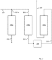
- Fig. 2 is a more detailed schematic diagram of an adsorption unit suitable for use in the plant of the invention and in performing the process of the invention.
- the adsorption unit according to Fig. 2 is suitable for a thermal swing adsorption process.
- the adsorption unit comprises three adsorbers (200a), (200b) and (200c), each of which contain an adsorbent effective to selectively adsorb organic sulfur compounds.
- each of the adsorbers will alternately rotate through the process steps of (1) an adsorption step for removal of organic sulfur compounds; (2) heat regeneration with a heated stream; and (3) cooling with a low temperature stream.
- the adsorption unit (101) is designed to allow switching between passing the fluid stream comprising sulfur compounds to each of the adsorbers and independently allow feeding the purge gas to each of the adsorbers.
- a fluid stream (201) comprising sulfur compounds, including organic sulfur compounds, is fed into the adsorption unit.
- a first part of the fluid stream (201), fluid stream (201a), is passed through adsorber (200a) so as to obtain an organic sulfur compounds-depleted fluid stream (202) and a spent adsorbent.
- the organic sulfur compounds-depleted fluid stream (202) is guided to an adsorber (not shown in Fig. 2 ), for instance an adsorber (104) as described with regard to Fig. 1 .
- Adsorber (200a) represents an adsorber which in the preceding steps of the process cycle has been heat regenerated and cooled.
- Adsorber (200b) represents an adsorber which in the preceding step of the process cycle has been heat regenerated.
- An effluent stream (203) is obtained.
- the effluent stream (203) is through a heater (204) to obtain a heated stream (205).
- Adsorber (200c) represents an adsorber which in the preceding step of the process cycle has been involved in the adsorption process and thus comprises a spent adsorbent.
- the heated stream (205) which preferably has a temperature of at least 140 °C, is passed through adsorber (200c) so as to obtain a heated, partially regenerated adsorbent and an organic sulfur compounds-containing purge gas (206).
- the organic sulfur compounds-containing purge gas (206) is guided to a processing unit (not shown in Fig. 2 ), for instance a processing unit (102) as described with regard to Fig. 1 .
- the adsorber can be recirculated to the starting point of the thermal swing adsorption process cycle, as represented by adsorber (200a), thus allowing for the thermal swing adsorption process to be continuous.
Applications Claiming Priority (1)
| Application Number | Priority Date | Filing Date | Title |
|---|---|---|---|
| EP19197069 | 2019-09-12 |
Publications (1)
| Publication Number | Publication Date |
|---|---|
| EP3808431A1 true EP3808431A1 (fr) | 2021-04-21 |
Family
ID=67953687
Family Applications (1)
| Application Number | Title | Priority Date | Filing Date |
|---|---|---|---|
| EP20192531.0A Withdrawn EP3808431A1 (fr) | 2019-09-12 | 2020-08-25 | Procédé et installation de désacidification d'un courant fluidique comprenant des composés de soufre, y compris des composés organiques de soufre |
Country Status (1)
| Country | Link |
|---|---|
| EP (1) | EP3808431A1 (fr) |
Cited By (1)
| Publication number | Priority date | Publication date | Assignee | Title |
|---|---|---|---|---|
| WO2023241997A1 (fr) * | 2022-06-14 | 2023-12-21 | Highview Enterprises Limited | Procédé et appareil de traitement de gaz |
Citations (12)
| Publication number | Priority date | Publication date | Assignee | Title |
|---|---|---|---|---|
| US4061724A (en) | 1975-09-22 | 1977-12-06 | Union Carbide Corporation | Crystalline silica |
| US4073865A (en) | 1976-09-27 | 1978-02-14 | Union Carbide Corporation | Silica polymorph and process for preparing same |
| US4310440A (en) | 1980-07-07 | 1982-01-12 | Union Carbide Corporation | Crystalline metallophosphate compositions |
| US4440871A (en) | 1982-07-26 | 1984-04-03 | Union Carbide Corporation | Crystalline silicoaluminophosphates |
| US4484933A (en) | 1983-06-14 | 1984-11-27 | Union Carbide Corporation | Process for drying gas streams |
| US4567027A (en) | 1983-07-19 | 1986-01-28 | Metallurgie Hoboken-Overpelt | Process for defluorinating an acid sulphate solution |
| US4853202A (en) | 1987-09-08 | 1989-08-01 | Engelhard Corporation | Large-pored crystalline titanium molecular sieve zeolites |
| US4938939A (en) | 1987-09-08 | 1990-07-03 | Engelhard Corporation | Preparation of small-pored crystalline titanium molecular sieve zeolites |
| US5089034A (en) * | 1990-11-13 | 1992-02-18 | Uop | Process for purifying natural gas |
| US5244650A (en) | 1989-06-29 | 1993-09-14 | Engelhard Corporation | Large-pored molecular sieves with charged octahedral titanium and charged tetrahedral aluminum sites |
| CA2461952A1 (fr) * | 2004-03-25 | 2005-09-25 | 1058238 Alberta Ltd. | Procede d'enrichissement en gaz acide |
| US7442233B2 (en) | 2005-07-06 | 2008-10-28 | Basf Catalysts Llc | Integrated heavy hydrocarbon removal, amine treating and dehydration |
-
2020
- 2020-08-25 EP EP20192531.0A patent/EP3808431A1/fr not_active Withdrawn
Patent Citations (12)
| Publication number | Priority date | Publication date | Assignee | Title |
|---|---|---|---|---|
| US4061724A (en) | 1975-09-22 | 1977-12-06 | Union Carbide Corporation | Crystalline silica |
| US4073865A (en) | 1976-09-27 | 1978-02-14 | Union Carbide Corporation | Silica polymorph and process for preparing same |
| US4310440A (en) | 1980-07-07 | 1982-01-12 | Union Carbide Corporation | Crystalline metallophosphate compositions |
| US4440871A (en) | 1982-07-26 | 1984-04-03 | Union Carbide Corporation | Crystalline silicoaluminophosphates |
| US4484933A (en) | 1983-06-14 | 1984-11-27 | Union Carbide Corporation | Process for drying gas streams |
| US4567027A (en) | 1983-07-19 | 1986-01-28 | Metallurgie Hoboken-Overpelt | Process for defluorinating an acid sulphate solution |
| US4853202A (en) | 1987-09-08 | 1989-08-01 | Engelhard Corporation | Large-pored crystalline titanium molecular sieve zeolites |
| US4938939A (en) | 1987-09-08 | 1990-07-03 | Engelhard Corporation | Preparation of small-pored crystalline titanium molecular sieve zeolites |
| US5244650A (en) | 1989-06-29 | 1993-09-14 | Engelhard Corporation | Large-pored molecular sieves with charged octahedral titanium and charged tetrahedral aluminum sites |
| US5089034A (en) * | 1990-11-13 | 1992-02-18 | Uop | Process for purifying natural gas |
| CA2461952A1 (fr) * | 2004-03-25 | 2005-09-25 | 1058238 Alberta Ltd. | Procede d'enrichissement en gaz acide |
| US7442233B2 (en) | 2005-07-06 | 2008-10-28 | Basf Catalysts Llc | Integrated heavy hydrocarbon removal, amine treating and dehydration |
Non-Patent Citations (2)
| Title |
|---|
| CHOWANIETZ VOLKMAR ET AL: "Temperature Dependent Adsorption of Sulfur Components, Water, and Carbon Dioxide on a Silica-Alumina Gel Used in Natural Gas Processing", JOURNAL OF CHEMICAL AND ENGINEERING DATA., vol. 61, no. 9, 14 July 2016 (2016-07-14), US, pages 3208 - 3216, XP055782530, ISSN: 0021-9568, Retrieved from the Internet <URL:https://pubs.acs.org/doi/pdf/10.1021/acs.jced.6b00301> DOI: 10.1021/acs.jced.6b00301 * |
| GUY WEBER ET AL: "Adsorption Equilibrium of Light Mercaptans on Faujasites", ADSORPTION, KLUWER ACADEMIC PUBLISHERS, BO, vol. 11, no. 1, 1 July 2005 (2005-07-01), pages 183 - 188, XP019203649, ISSN: 1572-8757, DOI: 10.1007/S10450-005-5920-9 * |
Cited By (1)
| Publication number | Priority date | Publication date | Assignee | Title |
|---|---|---|---|---|
| WO2023241997A1 (fr) * | 2022-06-14 | 2023-12-21 | Highview Enterprises Limited | Procédé et appareil de traitement de gaz |
Similar Documents
| Publication | Publication Date | Title |
|---|---|---|
| US7374734B2 (en) | Absorbing agent and method for eliminating acid gases from fluids | |
| AU2006265026B2 (en) | Integrated heavy hydrocarbon removal, amine treating and dehydration | |
| US6939393B2 (en) | Method for neutralizing a stream of fluid, and washing liquid for use in one such method | |
| US20070020163A1 (en) | Method for Removing Acid Gases and Ammonia from a Fluid Stream | |
| US7004997B2 (en) | Method for removal of acid gases from a gas flow | |
| US7749309B2 (en) | Method for deacidifying a fluid stream and washing liquid used in such a method | |
| MXPA05006242A (es) | Configuraciones y metodos para la remocion de gas acido y contaminantes con emision casi nula. | |
| WO2007007571A1 (fr) | Procédé d’élimination de composé contenant du soufre du gaz naturel | |
| US7425314B2 (en) | Process for removing sulphur compounds including hydrogen sulphide and mercaptans from gas streams | |
| US11278841B2 (en) | Removal of hydrogen sulphide and carbon dioxide from a stream of fluid | |
| CA3021567A1 (fr) | Utilisation de composes d'amine encombree a base de morpholine pour l'elimination selective de sulfure d'hydrogene | |
| US11724229B2 (en) | Process and plant for removing disruptive components from raw synthesis gas | |
| CA3000286A1 (fr) | Procede d'elimination selective de sulfure d'hydrogene | |
| EP1700630B1 (fr) | Procédé d'elimination de composés sulfururés de flu d'hydrocarbures gazeux au moyens d'adsorbants | |
| US20130211171A1 (en) | Method for removing acid gases from hydrocarbon-comprising fluids | |
| EA014385B1 (ru) | Способ получения газового потока, обедненного меркаптанами | |
| EP3808431A1 (fr) | Procédé et installation de désacidification d'un courant fluidique comprenant des composés de soufre, y compris des composés organiques de soufre | |
| EP1907101A1 (fr) | Procede de production d'un flux gazeux appauvri en sulfure d'hydrogene et en thiols | |
| EP3927450A1 (fr) | Procédé d'élimination de gaz acides d'un flux de fluide avec un absorbant liquide comprenant un anneau de pipérazine | |
| RU2739735C9 (ru) | Способ выделения углеводородов с 5-8 атомами углерода и кислых газов из потока текучей среды | |
| WO2022129977A1 (fr) | Procédé de récupération de dioxyde de carbone de haute pureté à partir d'un mélange gazeux | |
| EA043349B1 (ru) | Способ удаления кислых газов из потока текучей среды с помощью жидкого абсорбента, содержащего пиперазиновое кольцо | |
| JP2010174191A (ja) | 天然ガス処理における酸素消費量の低減方法 |
Legal Events
| Date | Code | Title | Description |
|---|---|---|---|
| PUAI | Public reference made under article 153(3) epc to a published international application that has entered the european phase |
Free format text: ORIGINAL CODE: 0009012 |
|
| STAA | Information on the status of an ep patent application or granted ep patent |
Free format text: STATUS: THE APPLICATION HAS BEEN PUBLISHED |
|
| AK | Designated contracting states |
Kind code of ref document: A1 Designated state(s): AL AT BE BG CH CY CZ DE DK EE ES FI FR GB GR HR HU IE IS IT LI LT LU LV MC MK MT NL NO PL PT RO RS SE SI SK SM TR |
|
| AX | Request for extension of the european patent |
Extension state: BA ME |
|
| STAA | Information on the status of an ep patent application or granted ep patent |
Free format text: STATUS: THE APPLICATION IS DEEMED TO BE WITHDRAWN |
|
| 18D | Application deemed to be withdrawn |
Effective date: 20211022 |