EP1571459B1 - Arrangement de bobines RF multirésonant - Google Patents
Arrangement de bobines RF multirésonant Download PDFInfo
- Publication number
- EP1571459B1 EP1571459B1 EP04030818A EP04030818A EP1571459B1 EP 1571459 B1 EP1571459 B1 EP 1571459B1 EP 04030818 A EP04030818 A EP 04030818A EP 04030818 A EP04030818 A EP 04030818A EP 1571459 B1 EP1571459 B1 EP 1571459B1
- Authority
- EP
- European Patent Office
- Prior art keywords
- coil
- electric current
- node
- additional
- magnetic field
- Prior art date
- Legal status (The legal status is an assumption and is not a legal conclusion. Google has not performed a legal analysis and makes no representation as to the accuracy of the status listed.)
- Not-in-force
Links
Images


Classifications
-
- G—PHYSICS
- G01—MEASURING; TESTING
- G01R—MEASURING ELECTRIC VARIABLES; MEASURING MAGNETIC VARIABLES
- G01R33/00—Arrangements or instruments for measuring magnetic variables
- G01R33/20—Arrangements or instruments for measuring magnetic variables involving magnetic resonance
- G01R33/28—Details of apparatus provided for in groups G01R33/44 - G01R33/64
- G01R33/32—Excitation or detection systems, e.g. using radio frequency signals
- G01R33/34—Constructional details, e.g. resonators, specially adapted to MR
- G01R33/34046—Volume type coils, e.g. bird-cage coils; Quadrature bird-cage coils; Circularly polarised coils
- G01R33/34069—Saddle coils
-
- G—PHYSICS
- G01—MEASURING; TESTING
- G01R—MEASURING ELECTRIC VARIABLES; MEASURING MAGNETIC VARIABLES
- G01R33/00—Arrangements or instruments for measuring magnetic variables
- G01R33/20—Arrangements or instruments for measuring magnetic variables involving magnetic resonance
- G01R33/28—Details of apparatus provided for in groups G01R33/44 - G01R33/64
- G01R33/32—Excitation or detection systems, e.g. using radio frequency signals
- G01R33/34—Constructional details, e.g. resonators, specially adapted to MR
- G01R33/34046—Volume type coils, e.g. bird-cage coils; Quadrature bird-cage coils; Circularly polarised coils
- G01R33/34053—Solenoid coils; Toroidal coils
-
- G—PHYSICS
- G01—MEASURING; TESTING
- G01R—MEASURING ELECTRIC VARIABLES; MEASURING MAGNETIC VARIABLES
- G01R33/00—Arrangements or instruments for measuring magnetic variables
- G01R33/20—Arrangements or instruments for measuring magnetic variables involving magnetic resonance
- G01R33/28—Details of apparatus provided for in groups G01R33/44 - G01R33/64
- G01R33/32—Excitation or detection systems, e.g. using radio frequency signals
- G01R33/36—Electrical details, e.g. matching or coupling of the coil to the receiver
- G01R33/3628—Tuning/matching of the transmit/receive coil
- G01R33/3635—Multi-frequency operation
-
- G—PHYSICS
- G01—MEASURING; TESTING
- G01R—MEASURING ELECTRIC VARIABLES; MEASURING MAGNETIC VARIABLES
- G01R33/00—Arrangements or instruments for measuring magnetic variables
- G01R33/20—Arrangements or instruments for measuring magnetic variables involving magnetic resonance
- G01R33/28—Details of apparatus provided for in groups G01R33/44 - G01R33/64
- G01R33/32—Excitation or detection systems, e.g. using radio frequency signals
- G01R33/34—Constructional details, e.g. resonators, specially adapted to MR
- G01R33/34015—Temperature-controlled RF coils
- G01R33/34023—Superconducting RF coils
Definitions
- the present invention relates to a nuclear magnetic resonance (NMR) system that enables multiplex resonance measurement which generates a plurality of frequencies at the same time and measures the resonance of a plurality of nuclei.
- NMR nuclear magnetic resonance
- NMR nuclear magnetic resonance
- B 0 uniform high magnetic field
- a superconductivity magnet is generally employed.
- a high magnetic field NMR system mainly intended for structural analysis of protein material, and an NMR system of 21.6 T(920 MHz) is produced.
- it is necessary to enhance the uniformity of a magnetic field intensity and it is desirable that a variation of the magnetic field intensity in a region where a sample to be measured exists is 10 -9 or less.
- a high sensitivity is demanded for a probe that receives a free induction decay (FID) signal generated according to a supplied high frequency pulse.
- FID free induction decay
- the main noise in the probe is derived from an electric resistance of the probe that constitutes a resonator, and depends on the temperature and the high frequency loss resistance of the material.
- a probe coil and a preamplifier are located at a low temperature, and there is used a high temperature superconductivitymaterial that is lower in the high frequency loss resistance than normal metal such as copper by two figures or more, as disclosed in USP 5,247,256 .
- the probe coil is arranged in such a manner that the high frequency magnetic field is orthogonal to the static magnetic field when an electricity is fed to the probe coil. Since a sample tube into which a sample to be measured is incorporated is inserted in a vertical direction, the following arrangement is used.
- an NMR system using the superconductivity magnet that generates a static magnetic field in a horizontal direction is called “horizontal NMR system”
- an NMR system using the superconductivity magnet that generates a static magnetic field in a vertical direction is called “vertical NMR system”.
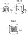
- Figs. 1A to 1C show a conventional horizontal NMR system, in which Fig. 1A is a perspective view of a superconductivity solenoid coil 11, Fig. 1B is a perspective view of a saddle coil 12, and Fig. 1C is a perspective view showing the arrangement of the superconductivity solenoid coil 11 and the saddle coil 12.
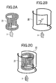
- Figs. 2A to 2C show a conventional vertical NMR system, in which Fig. 2A is a perspective view of a superconductivity saddle coil 21, Fig. 2B is a perspective view of a saddle coil 22, and Fig. 2C is a perspective view showing the arrangement of the superconductivity solenoid coil 21 and the saddle coil 22.
- the solenoid coil 11 shown in Fig. 1A is used as a reception probe coil.
- the saddle coil 21 shown in Fig. 2A is used as the reception probe coil.
- the probe coil is made of normal metal, there are many cases in which the probe coil transmits and receives the high frequency magnetic field.
- the probe coil is formed of a superconductivity thin film
- the probe coil is used for only receiving the high frequency magnetic field since the superconductivity thin film does not withstand a large high-frequency current.
- a saddle coil is disposed outside of the probe coil for transmission of the high frequency magnetic field.
- the reception probe coil 11 and the transmission probe coil 12 are arranged as shown in Fig. 1C .
- the reception probe coil 21 and the transmission probe coil 22 are arranged as shown in Fig. 2C .
- document US 5,929,639 discloses a nuclear magnetic resonance system for multinuclear magnetic resonance measurements of at least a first, a second and a third nuclear species, comprising:
- US 4,996,481 discloses an NMR system with transmission and reception decoupled from one another by geometrically stacking their current loops.
- the MNR measurement conducts multiplex resonance that generates a plurality of frequencies at the same time and measures the resonance of a plurality of nuclei.
- nuclear species of 1H, 2H, 13C, 15N or the like are measured.
- the resonance frequencies of the respective nuclear species are different from each other. For example, when a static magnetic field intensity is 14.1 tesla, a resonance frequency of 1H is about 600 MHz, a resonance frequency of 2H is about 92.1 MHz, a resonance frequency of 13C is about 150.9 MHz, and a resonance frequency of 15N is about 60.8 MHz.
- two tuning circuits are incorporated to conduct double tunings.
- the double tunings generally deteriorate the performance by about 20 to 30 %.
- the frequencies of the nuclear species are in proximity to each other, each other' s frequencies cannot be cut off , thereby making it hard to implement triple tunings.
- the resonance frequencies of 2H and 15N are in proximity to each other, and it is difficult to cut off each other's frequencies.
- the present invention has been made to solve the above problem, and therefore an object of the present invention is to provide a nuclear magnetic resonance system that is capable of conducting multiplex resonance measurement without largely deteriorating the sensitivities of a superconductivity reception coil and a transmission coil.
- the nuclear magnetic resonance (NMR) system conducts multiplex resonance measurement intended for three or more kinds of nuclear species with the structure as defined in claim 1. That is, the nuclear magnetic resonance system is made up of a superconductivity reception coil, a transmitting coil and four electric current loops, and also includes a coil (hereinafter referred to as "additional coil” (or a self-shield coil) in which directions of currents that flow in an inner loop and an outer loop are opposite to each other) as a basic structure.
- additional coil or a self-shield coil
- a direction of a high frequency magnetic field that is developed in the center of the additional coil when electricity is fed to the additional coil is substantially identical with a direction of a high frequency magnetic field that is developed in the center of the transmission coil when electricity is fed to the transmission coil.
- a current loop of the transmission coil is arranged between the inner loop and the outer loop of the additional coil, desirably substantially in the middle therebetween.
- the NMR system according to the present invention can conduct multiplex resonance measurement without largely deteriorating the sensitivities of the superconductivity reception coil and the transmission coil.
- a nuclear magnetic resonance system that can conduct multiplex resonance measurement intended for three ormore kinds of nuclear species without largely deteriorating the sensitivities of the superconductivity reception coil and the transmission coil.
- the present invention relates to a coil configuration of a probe for transmitting a high frequency signal at a predetermined resonance frequency and receiving a free induction decay (FID) signal with respect to a sample that is located in a uniform magnetic field B 0 , and a structure for mounting the probe, inanuclearmagneticresonance (NMR) system.
- FID free induction decay
- the present invention is applied to an NMR system (horizontal NMR system) using a superconductivity magnet that develops a static magnetic field in a horizontal direction as shown in Fig. 4 , and an NMR system (vertical NMR system) using a superconductivitymagnet that develops a staticmagnetic field in a vertical direction as shown in Fig. 7 .
- the present invention can conduct multiplex resonance measurement by using another coil (additional coil) without largely deteriorating the sensitivities of the superconductivity reception coil and the transmission coil in a nuclear magnetic resonance (NMR) spectroscopy.
- another coil additional coil
- NMR nuclear magnetic resonance
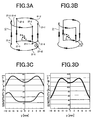
- Fig. 3A is a perspective view showing a saddle coil (first saddle coil) 12
- Fig. 3B is a perspective view showing a second saddle coil 31
- Fig. 3C is a graph showing a sensitivity distribution of the saddle coil (first saddle coil) 12
- Fig. 3D is a graph showing a sensitivity distribution of the second saddle coil 31.
- nodes 37-1 to 37-10 are shown in Fig. 3A .
- a conductor 61-1 is a conductor that connects a node 37-2 and a node 37-3 with a curve
- a conductor 61-2 is a conductor that connects a node 37-7 and a node 37-8 with a curve.
- a node 37-1 and a node 37-6 are symmetricallypositionedwith respect to the x-z plane.
- the node 37-2 and the node 37-7 are symmetrically positioned with respect to the x-z plane.
- the node 37-3 and the node 37-8 are symmetrically positioned with respect to the x-z plane.
- a node 37-4 and a node 37-9 are symmetrically positioned with respect to the x-z plane.
- a node 37-5 and a node 37-10 are symmetrically positioned with respect to the x-z plane.
- a conductor route that functions as one loop such as a conductor route that connects the nodes 37-1, 37-2, 37-3, 37-4 and 37-5 is called "electric current loop" in the present specification.
- a conductor route that connects the nodes 37-6, 37-7, 37-8, 37-9 and 37-10 is an electric current loop.
- the saddle coil 12 has two electric current loops. Those two electric current loops are symmetrically positioned with respect to the x-z plane, and a direction of electric current is the same on those two electric current loops. Therefore, the high frequency magnetic field that is developed in the center of the saddle coil 12 when electricity is fed to the saddle coil 12 is in the y-direction.
- the second saddle 31 has tuned in to a frequency (92.1 MHz) of 2H nuclear species is disposed inside of the saddle coil 12 that tuned in to a frequency (600 MHz) of 1H nuclear species in the static magnetic field intensity 14.1 tesla.
- the second saddle 31 also has two electric current loops as with the saddle coil 12 although the dimensions are different from those of the saddle coil 12.
- the high frequency magnetic field that is developed in the center of the second saddle coil 31 when electricity is fed to the second saddle coil 31 is in the y-direction.
- Fig. 3C shows the sensitivity distribution of the saddle coil (first saddle coil) 12 on the y-axis at 600 MHz.
- Fig. 3D shows the sensitivity distribution of the second saddle coil 31 on the y-axis at 92.1 MHz.
- a solid line indicates the sensitivity distribution in the case where only the saddle coil (first saddle coil) 12 exists
- a dotted line indicates the sensitivity distribution in the case where the second saddle coil 31 exists inside of the saddle coil 12. It is understood from Fig. 3C that the existence of the second saddle coil 31 deteriorates the center sensitivity of the saddle coil (first saddle coil) 12 down to about 1/4.
- a solid line indicates the sensitivity distribution in the case where only the second saddle coil 31 exists
- a dotted line indicates the sensitivity distribution in the case where the saddle coil (first saddle coil) 12 exists outside of the second saddle coil 31.
- the solid line and the dotted line are substantially superimposed on each other, and the sensitivity of the second saddle coil 31 hardly changes regardless of the presence or absence of the arrangement of the saddle coil (first saddle coil) 12 outside thereof.
- the fact that the additional provision of another coil (second saddle coil 31) largely deteriorates the sensitivity of the first transmission coil (saddle coil (first saddle coil) 12) is remarkably disadvantageous in the NMR measurement.
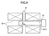
- Fig. 4 is a schematic diagram showing a structure of an NMR system (horizontal NMR system) according to a first embodiment of the present invention.
- Two divided superconductivity magnets 30-1 and 30-2 develop a uniform magnetic field B 0 of 14.1 tesla (T).
- the static magnetic field is in the z-direction.
- a low-temperature probe 33 that can cool the probe coil down to 10 K is located within the static magnetic field.
- a glass tube 32 having an inner diameter of 5 mm into which a sample is disposed is inserted into a thermally insulated inner side of the low-temperature probe.
- the sample tube into which the sample to be measured is disposed is inserted vertically into the lower-temperature probe.
- the solenoid coil 11 shown in Fig. 1A is employed as a 1H reception probe coil.
- the direction of the high frequency magnetic field that is developed in the center of the solenoid coil 11 when electricity is fed to the coil 11 is defined as an x-direction.
- the resonance frequency of the solenoid coil 11 tunes in to the resonance frequency 600 MHz of 1H at the static magnetic field intensity 14.1 tesla.
- the solenoid coil 11 is formed of a superconductivity thin film and used for only the reception coil.
- Fig. 5A is a perspective view showing the saddle coil 12 in the NMR system according to this embodiment.
- Fig. 5B is a perspective view showing a coil (additional coil) 55 which has four electric current loops in which directions of electric currents that flow in the inner loop and the outer loop are opposite to each other in the NMR system according to this embodiment.
- Fig. 5C is a graph showing a sensitivity distribution of the saddle coil in the NMR system according to this embodiment.
- Fig. 5D is a graph showing a sensitivity distribution of the coil shown in Fig. 5B in the NMR system according to this embodiment.
- Bold arrows shown in Figs. 5A and 5B indicate directions along which the current flow.
- the saddle coil 12 shown in Fig. 5A is employed as the transmission coil.
- the saddle coil 12 has two electric current loops in which a direction of electric current is the same on the two loops.
- the high frequency magnetic fields that are developed by those two electric current loops are in the y-direction in the center of the coil.
- the directions of the high frequency magnetic fields that are developed in the centers of the solenoid coil 11 and the saddle coil 12 when electricity is fed to the respective coils are orthogonal to each other, and also orthogonal to the static magnetic field (z-direction). Because the directions of the high frequency magnetic fields that are developed in the centers of the respective coils are orthogonal to each other, there is no electromagnetic coupling between those high frequency magnetic fields.
- the saddle coil 12 doubly tunes in to the resonance frequency 600 MHz of 1H and the resonance frequency 60.8 MHz of 15N at the static magnetic field intensity 14.1 tesla.
- the saddle coil 12 may be used only for transmission or commonly for transmission and reception. For example, the reception of 15N can be performed by means of the saddle coil 12.
- the coil 55 shown in Fig. 5B is employed as the additional coil.
- the coil 55 has four electric current loops in which directions of electric currents that flow in the inner loop and the outer loop are opposite to each other.
- the coil 55 tunes in to the resonance frequency 92.1 MHz of 2H.
- the coil 55 conducts transmission and reception of 2H.
- a conductor 62-1 is a conductor that connects a node 57-8 and a node 57-9 with a curve
- a conductor 62-2 is a conductor that connects a node 57-2 and a node 57-3 with a curve
- a conductor 62-3 is a conductor that connects a node 57-12 and a node 57-13 with a curve
- a conductor 62-4 is a conductor that connects a node 57-18 and a node 57-19 with a curve.
- a node 57-1 and a node 57-11 are symmetrically positioned on the x-z plane.
- the node 57-2 and a node 57-12 are symmetrically positioned on the x-z plane.
- the node 57-3 and a node 57-13 are symmetrically positioned on the x-z plane.
- the node 57-4 and a node 57-14 are symmetrically positioned on the x-z plane.
- the node 57-5 and a node 57-15 are symmetrically positioned on the x-z plane.
- the node 57-6 and a node 57-16 are symmetrically positioned on the x-z plane.
- the node 57-7 and a node 57-17 are symmetrically positioned on the x-z plane.
- the node 57-8 and a node 57-18 are symmetrically positioned on the x-z plane.
- the node 57-9 and a node 57-19 are symmetrically positioned on the x-z plane.
- the node 57-10 and a node 57-20 are symmetrically positioned on the x-z plane.
- a conductor route that connects the nodes 57-1, 57-2, 57-3, 57-4 and 57-5 composes an electric current loop.
- a conductor route that connects the nodes 57-6, 57-7, 57-8, 57-9 and 57-10 composes an electric current loop.
- a conductor route that connects the nodes 57-11, 57-12, 57-13, 57-14 and 57-15 composes an electric current loop.
- a conductor route that connects the nodes 57-16, 57-17, 57-18, 57-19 and 57-20 composes an electric current loop. That is, the coil 55 shown in Fig. 5B has four electric current loops.
- the current loop (conductor route) that connects the nodes 57-1, 57-2, 57-3, 57-4 and 57-5, and the current loop (conductor route) that connects the nodes 57-11, 57-12, 57-13, 57-14 and 57-15 are called “inner loop” in the present specification.
- the current loop (conductor route) that connects the nodes 57-6, 57-7, 57-8, 57-9 and 57-10, and the current loop (conductor route) that connects the nodes 57-16, 57-17, 57-18, 57-19 and 57-20 are called “outer loop" in the present specification.
- a distance between the inner loops and the origin is shorter than a distance between the outer loops and the origin.
- the high frequency magnetic field that is developed in the center of the coil 55 shown in Fig. 5B when electricity is fed to the coil 55 is in the y direction. Therefore, the high frequency magnetic field developed by the coil 55 is electromagnetically orthogonal to that by the solenoid coil 11, and there is no electromagnetic coupling between those high frequency magnetic fields.
- the high frequency magnetic fields that are developed when electricity is fed to the coil 55 and the saddle coil 12 shown in Fig. 5B are in the y-direction in the center of those coils. However, even if the coil shown in Fig. 5B is added, the sensitivities of the saddle coil 12 and the additional coil are not largely deteriorated.
- Fig. 5C shows a sensitivity distribution of the saddle coil 12 on the y axis.
- Fig. 5D shows a sensitivity distribution of the coil 55 shown in Fig. 5B on the y-axis.
- a solid line indicates the sensitivity distribution in the case where only the saddle coil 12 exists
- a dotted line indicates the sensitivity distribution in the case where the coil 55 shown in Fig. 5B exists together with the saddle coil 12. It is understood from Fig. 5C that the solid line and the dotted line are substantially superimposed on each other, and the sensitivity of the saddle coil 12 hardly changes regardless of the presence or absence of the arrangement of the coil 55 shown in Fig. 5B .
- a solid line indicates the sensitivity distribution in the case where only the coil 55 shown in Fig. 5B exists
- a dotted line indicates the sensitivity distribution in the case where the coil 55 exists together with the saddle coil 12.
- the sensitivity in the case where the saddle coil 12 exists together is more deteriorated by about several %.
- the solid line and the dotted line are substantially superimposed on each other, and the sensitivity of the coil 55 shown in Fig. 5B does not largely change regardless of the presence or absence of the arrangement of the saddle coil 12.
- multiplex resonance can be performed with respect to three or more kinds of nuclear species.
- a measurement sequence in which while the frequency of 15N continues to be transmitted by means of the saddle coil 12, a frequency lock is conducted at 2H by means of the coil 55 shown in Fig. 5B , and a reception of 1H is conducted by means of the solenoid coil 11.
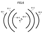
- Fig. 6 is a diagram showing an arrangement of conductors on a plane (y-z plane) that is orthogonal to a vertical direction of the saddle coil 12 and the coil 55 shown in Fig. 5B when viewing those two coils from the vertical direction.
- Reference 61-1 and 61-2 denotes conductors that constitute the saddle coil 12, and reference 62-1, 62-2, 62-3 and 62-4 denotes conductors that constitute the coils 55 shown in Fig. 5B .
- the conductor 61-1 is disposed between the conductor 62-1 and the conductor 62-2, and the conductor 61-2 is disposed between the conductor 62-3 and the conductor 62-4.
- the conductor 61-1 is disposed in the middle of the conductor 62-1 and the conductor 62-2, and the conductor 61-2 is disposed in the middle of the conductor 62-3 and the conductor 62-4.
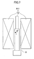
- Fig. 7 is a schematic diagram showing a structure of an NMR system (vertical NMR system) according to a second embodiment of the present invention.
- a uniform magnetic field B 0 of 14.1 tesla (T) is developed vertically by a superconductivity magnet 30-3. It is assumed that the direction of the static magnetic field is a z-direction.
- a low-temperature probe 33 that can cool the probe coil down to 10 K is located within the static magnetic field.
- a glass tube 32 having an inner diameter of 5 mm into which a sample is disposed is inserted into a thermally insulated inner side of the low-temperature probe.
- the sample tube into which the sample to be measured is disposed is inserted vertically into the lower-temperature probe.
- the saddle coil 21 shown in Fig. 2A is employed as a 1H reception probe coil.
- the direction of the high frequency magnetic field that is developed in the center of the reception probe coil 21 when electricity is fed to the coil 21 is defined as an x-direction.
- the resonance frequency of the reception probe coil 21 tunes in to the resonance frequency 600 MHz of 1H at the static magnetic field intensity 14.1 tesla.
- the reception probe coil 21 is formed of a superconductivity thin film and used for only the reception coil.
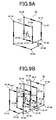
- Fig. 8A is a perspective view showing the saddle coil 22 in the NMR system according to this embodiment.
- Fig. 8B is a perspective view showing a coil (additional coil) 85 which has four electric current loops in which directions of electric currents that flow in the inner loop and the outer loop are opposite to each other in the NMR system according to this embodiment.
- Fig. 8C is a graph showing a sensitivity distribution of the saddle coil 22 in the NMR system according to this embodiment.
- Fig. 8D is a graph showing a sensitivity distribution of the coil 85 shown in Fig. 8B in the NMR system according to this embodiment.
- Bold arrows shown in Figs. 8A and 8B indicate directions along which the current flow.
- the saddle coil 22 shown in Fig. 8A is employed as the transmission coil.
- the saddle coil 22 has two electric current loops (conductor routes) 81-1 and 81-2 in which a direction of electric current is the same on the two loops 81-1 and 81-2.
- the directions of the high frequency magnetic fields that are developed by those two electric current loops are they-direction in the center of the coil.
- the directions of the high frequency magnetic fields that are developed in the centers of the reception probe coil 21 and the saddle coil 22 when electricity is fed to the respective coils are orthogonal to each other, and also orthogonal to the static magnetic field (z-direction) . Because the directions of the high frequency magnetic fields that are developed in the centers of the respective coils are orthogonal to each other, there is no electromagnetic coupling between those high frequency magnetic fields.
- the saddle coil 22 doubly tunes in to the resonance frequency 600 MHz of 1H and the resonance frequency 60.8 MHz of 15N at the static magnetic field intensity 14.1 tesla.
- the saddle coil 22 may be used only for transmission or commonly for transmission and reception. For example, the reception of 15N can be performed by means of the saddle coil 22.
- the coil 85 shown in Fig. 8B is employed as another coil (additional coil).
- the coil 85 has four electric current loops 82-1, 82-2, 82-3 and 82-4 in which directions of electric currents that flow in the inner loop and the outer loop are opposite to each other.
- the coil 85 tunes in to the resonance frequency 92.1 MHz of 2H.
- the direction of the high frequency magnetic field that is developed when electricity is fed to the coil 85 shown in Fig. 8B is the y-direction in the center of the coil. For that reason, the high frequency magnetic field developed by the coil 85 is electromagnetically orthogonal to that by the solenoid coil 21, and there is no electromagnetic coupling between those high frequency magnetic fields.
- the high frequency magnetic fields that are developed when electricity is fed to the coil 85 and the saddle coil 22 shown in Fig. 8B are in the y-direction in the center of those coils. However, even if the coil 85 shown in Fig. 8B is added, the sensitivities of the saddle coil 22 and the coil 85 are not largely deteriorated.
- Fig. 8C shows a sensitivity distribution of the saddle coil 22 on the y-axis.
- Fig. 8D shows a sensitivity distribution of the coil 85 shown in Fig. 8B on the y-axis.
- a solid line indicates the sensitivity distribution in the case where only the saddle coil 22 exists
- a dotted line indicates the sensitivity distribution in the case where the coil 85 shown in Fig. 8B exists together with the saddle coil 22. It is understood from Fig. 8C that the solid line and the dotted line are substantially superimposed on each other, and the sensitivity of the saddle coil 22 hardly changes regardless of the presence or absence of the arrangement of the coil 85 shown in Fig. 8B .
- a solid line indicates the sensitivity distribution in the case where only the coil 85 shown in Fig. 8B exists
- a dotted line indicates the sensitivity distribution in the case where the coil 85 exists together with the saddle coil 22.
- the sensitivity in the case where the saddle coil 22 exists together is more deteriorated by about several %.
- the solid line and the dotted line are substantially superimposed on each other, and the sensitivity of the coil 85 shown in Fig. 8B does not largely change regardless of the presence or absence of the arrangement of the saddle coil 22.
- multiplex resonance measurement can be performed with respect to three or more kinds of nuclear species. For example, there can be implemented a measurement sequence in which while the frequency of 15N continues to be transmitted by means of the saddle coil 22, a frequency lock is conducted at 2H by means of the coil 85 shown in Fig. 8B , and a reception of 1H is conducted by means of the reception probe coil 21.
- multiplex resonance can be measured with respect to three or more kinds of nuclear species by using a coil (additional coil) that has four electric current loops in which directions of electric currents that flow in the inner loop and the outer loop are opposite to each other, in addition to the superconductivity reception coil and the transmission coil.
- the transmission coil and the additional coil may be configured as shown in Figs. 9A and 9B .
- Fig. 9A is a perspective view showing a coil 90 that has two electric current loops in which a direction of electric current is the same on the two loops according to a third embodiment of the present invention.
- Fig. 9B is a perspective view showing a coil (additional coil) 93 which has four electric current loops (conductor routes) in which directions of electric currents that flow in the inner loop and the outer loop are opposite to each other according to the third embodiment of the present invention.
- Bold arrows shown in Figs. 9A and 9B indicate directions along which the current flow.
- the coil 90 shown in Fig. 9A has two electric current loops in which a direction of electric current is the same on the two loops.
- the coil 93 shown in Fig. 9B has four electric current loops in which directions of electric currents that flow in the inner loop and the outer loop are opposite to each other.
- nodes 37-21 to 37-30 are indicated in Fig.9A .
- a conductor 91-1 is a conductor that connects a node 37-22 and a node 37-23 with a curve
- a conductor 91-2 is a conductor that connects a node 37-27 and a node 37-28 with a curve.
- a node 37-21 and a node 37-26 are symmetrically positioned on the x-z plane.
- a node 37-22 and a node 37-27 are symmetrically positioned on the x-z plane.
- a node 37-23 and a node 37-28 are symmetrically positioned on the x-z plane.
- the node 37-24 and a node 37-29 are symmetrically positioned on the x-z plane.
- the node 37-25 and a node 37-30 are symmetrically positioned on the x-z plane.
- a conductor route that connects the nodes 37-21, 37-22, 37-23, 37-24 and 37-25 composes one electric current loop.
- a conductor route that connects the nodes 37-26, 37-27, 37-28, 37-29 and 37-30 composes another electric current loop.
- the coil 90 has two electric current loops. Those two electric current loops are symmetrically positioned with respect to the x-z plane, and a direction of electric current is the same on the two electric current loops.
- a conductor 92-1 is a conductor that connects a node 57-38 and a node 57-39 with a curve
- a conductor 92-2 is a conductor that connects a node 57-32 and a node 57-33 with a curve
- a conductor 92-3 is a conductor that connects a node 57-42 and a node 57-43 with a curve
- a conductor 92-4 is a conductor that connects a node 57-48 and a node 57-49 with a curve.
- a node 57-31 and a node 57-41 are symmetrically positioned on the x-z plane.
- the node 57-32 and a node 57-42 are symmetrically positioned on the x-z plane.
- the node 57-33 and a node 57-43 are symmetrically positioned on the x-z plane.
- the node 57-34 and a node 57-44 are symmetrically positioned on the x-z plane.
- the node 57-35 and a node 57-45 are symmetrically positioned on the x-z plane.
- the node 57-36 and a node 57-46 are symmetrically positioned on the x-z plane.
- the node 57-37 and a node 57-47 are symmetrically positioned on the x-z plane.
- the node 57-38 and a node 57-48 are symmetrically positioned on the x-z plane.
- the node 57-39 and a node 57-49 are symmetrically positioned on the x-z plane.
- the node 57-40 and a node 57-50 are symmetrically positioned on the x-z plane.
- a conductor route that connects the nodes 57-31, 57-32, 57-33, 57-34 and 57-35 composes an electric current loop.
- a conductor route that connects the nodes 57-36, 57-37, 57-38, 57-39 and 57-40 composes an electric current loop.
- a conductor route that connects the nodes 57-41, 57-42, 57-43, 57-44 and 57-45 composes an electric current loop.
- a conductor route that connects the nodes 57-46, 57-47, 57-48, 57-49 and 57-50 composes an electric current loop. That is, the coil 93 has four electric current loops.
- the electric current loop (conductor route) that connects the nodes 57-31, 57-23, 57-33, 57-34 and 57-35, and the electric current loop (conductor route) that connects the nodes 57-41, 57-42, 57-43, 57-44 and 57-45 are called “inner loop”.
- the electric current loop (conductor route) that connects the nodes 57-36, 57-37, 57-38, 57-39 and 57-40, and the electric current loop (conductor route) that connects the nodes 57-46, 57-47, 57-48, 57-49 and 57-50 are called "outer loop".
- the direction of electric current on the outer loop is opposite to the direction of electric current on the inner loop.
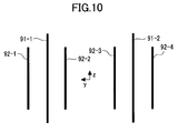
- Fig. 10 is a diagram showing an arrangement of conductors on a plane (y-z plane) that is orthogonal to a vertical direction of the coil 90 shown in Fig. 9A and the coil 93 shown in Fig. 9B when viewing those two coils from the vertical direction.
- Reference 91-1 and 91-2 denotes conductors that constitute the coil 90 shown in Fig. 9A
- reference 92-1, 92-2, 92-3 and 92-4 denotes conductors that constitute the coils 93 shown in Fig. 9B
- the conductor 91-1 is disposed between the conductor 92-1 and the conductor 92-2
- the conductor 91-2 is disposed between the conductor 92-3 and the conductor 92-4.
- the conductor 91-1 is disposed in the middle of the conductor 92-1 and the conductor 92-2, and the conductor 91-2 is disposed in the middle of the conductor 92-3 and the conductor 92-4.
- a magnet of a static magnetic field intensity that is different from 14.1 tesla can be used, and nuclear species other than 15N, 2H, 1H and 13C can be measured.
- the combination of the nuclear species that are dealt with by the saddle coil and the additional coil can be arbitrarily set.
- the saddle coil doubly tunes in to the resonance frequency of 1H and the resonance frequency of 2H so that the saddle coil can be used for transmission of 1H and for transmission and reception of 2H, and the additional coil can be used for transmission and reception of 15N.
- the saddle coil doubly tunes in to the resonance frequency of 1H and the resonance frequency of 2H so that the saddle coil can be used for transmission of 1H and for transmission and reception of 2H
- the additional coil doubly tunes in to the resonance frequency of 15N and the resonance frequency of 13C so that the additional coil can be used for transmission of 15N and 13C.
- the sensitivity in the NMR is an electric power that is induced in the coil by magnetization in a unit volume, and the electric power value is equal to a magnetic field intensity that is developed at the respective positions when an electric power of 1 watt is supplied to the coil.
Landscapes
- Physics & Mathematics (AREA)
- Condensed Matter Physics & Semiconductors (AREA)
- General Physics & Mathematics (AREA)
- Magnetic Resonance Imaging Apparatus (AREA)
Claims (4)
- Système de résonance magnétique nucléaire pour des mesures de résonance magnétique multinucléaire d'au moins une première, une deuxième et une troisième espèces nucléaires, comportant :des moyens (30) pour générer un champ magnétique statique sensiblement uniforme dans une première direction (z),une bobine de transmission RF en forme de selle (12, 22, 90) ayant deux boucles de courant électrique, conçue pour transmettre des signaux à haute fréquence à des première et deuxième fréquences de résonance prédéterminées, mutuellement différentes, des première et deuxième espèces nucléaires, à un échantillon dans une cuve tubulaire (32) qui est placée dans le champ magnétique statique sensiblement uniforme,une bobine de réception RF supraconductrice (11, 21) conçue pour recevoir un signal d'induction libre à la première fréquence de résonance prédéterminée en provenance de l'échantillon, etune bobine RF supplémentaire (55, 85, 93) ayant quatre boucles de courant électrique, conçue pour transmettre à l'échantillon des signaux à haute fréquence à une troisième fréquence de résonance prédéterminée de la troisième espèce nucléaire, la troisième fréquence de résonance prédéterminée étant différente des première et deuxième fréquences de résonance prédéterminées,dans lequel la bobine de transmission RF en forme de selle (12, 22, 90), la bobine RF supplémentaire (55, 85, 93) et la bobine de réception RF supraconductrice (11, 21) sont conçues de telle sorte que les champs magnétiques développés aux centres de la bobine de transmission RF en forme de selle et de la bobine RF supplémentaire, lorsque de l'électricité est fournie auxdites bobines, s'étendent tous les deux le long d'une même deuxième direction (y) orthogonale à la première direction et le champ magnétique développé au centre de la bobine de réception RF supraconductrice, lorsque de l'électricité est fournie à la bobine, s'étend long d'une troisième direction (x) orthogonale à la première direction (z) et à la deuxième direction (y), respectivement,
dans lequel les quatre boucles de courant électrique de la bobine RF supplémentaire sont constituées de deux boucles de courant électrique extérieures symétriques l'une à l'autre par rapport à un plan incluant la première direction (z) et la troisième direction (x), et de deux boucles de courant électrique intérieures symétriques l'une à l'autre par rapport au même plan et agencées plus près du plan que les boucles de courant électrique extérieures,
dans lequel les deux boucles de courant électrique de la bobine de transmission RF en forme de selle (12, 22, 90) sont également agencées symétriquement par rapport audit plan,
dans lequel la bobine RF supplémentaire (55, 85, 93) est conçue de telle sorte que les directions du courant circulant dans ses deux boucles de courant électrique intérieures sont identiques l'une à l'autre et opposées aux directions du courant circulant dans ses deux boucles de courant électrique extérieures,
dans lequel chacune des boucles de courant de la bobine de transmission RF en forme de selle (12, 22, 90) est agencée entre une boucle de courant électrique intérieure et une boucle de courant électrique extérieure de la bobine RF supplémentaire (55, 85, 93) du même côté dudit plan de manière à réduire le couplage électromagnétique entre la bobine de transmission RF en forme de selle (12, 22, 90) et la bobine RF supplémentaire (55, 85, 93). - Système de résonance magnétique nucléaire selon la revendication 1, dans lequel chacune des deux boucles de courant électrique de la bobine de transmission RF en forme de selle (12, 22, 90) est agencée pratiquement au milieu entre la boucle de courant électrique intérieure et la boucle de courant électrique extérieure de la bobine RF supplémentaire (55, 85, 93) du même côté dudit plan.
- Système de résonance magnétique nucléaire selon la revendication 1 ou 2, dans lequel
les moyens pour générer un champ magnétique sensiblement uniforme sont un aimant supraconducteur (30) développant le champ magnétique statique sensiblement uniforme dans une direction horizontale ou une direction verticale. - Système de résonance magnétique nucléaire selon l'une quelconque des revendications précédentes, dans lequel la bobine RF supplémentaire (55, 85, 93) est également conçue pour transmettre et recevoir des signaux à haute fréquence à une quatrième fréquence de résonance prédéterminée.
Applications Claiming Priority (2)
| Application Number | Priority Date | Filing Date | Title |
|---|---|---|---|
| JP2004057464A JP4105646B2 (ja) | 2004-03-02 | 2004-03-02 | 核磁気共鳴装置 |
| JP2004057464 | 2004-03-02 |
Publications (3)
| Publication Number | Publication Date |
|---|---|
| EP1571459A2 EP1571459A2 (fr) | 2005-09-07 |
| EP1571459A3 EP1571459A3 (fr) | 2005-11-30 |
| EP1571459B1 true EP1571459B1 (fr) | 2008-12-03 |
Family
ID=34747621
Family Applications (1)
| Application Number | Title | Priority Date | Filing Date |
|---|---|---|---|
| EP04030818A Not-in-force EP1571459B1 (fr) | 2004-03-02 | 2004-12-27 | Arrangement de bobines RF multirésonant |
Country Status (4)
| Country | Link |
|---|---|
| US (1) | US7141975B2 (fr) |
| EP (1) | EP1571459B1 (fr) |
| JP (1) | JP4105646B2 (fr) |
| DE (1) | DE602004018100D1 (fr) |
Cited By (1)
| Publication number | Priority date | Publication date | Assignee | Title |
|---|---|---|---|---|
| DE102022206766B3 (de) | 2022-07-01 | 2023-11-30 | Bruker Switzerland Ag | NMR-Probenkopf mit einer Sende-Empfangsspule umfassend einen Hinwicklungsabschnitt und einen Rückwicklungsabschnitt |
Families Citing this family (4)
| Publication number | Priority date | Publication date | Assignee | Title |
|---|---|---|---|---|
| JP4971685B2 (ja) * | 2006-05-25 | 2012-07-11 | 株式会社日立製作所 | 核磁気共鳴プローブコイル |
| JP4861149B2 (ja) | 2006-12-08 | 2012-01-25 | 株式会社日立製作所 | 核磁気共鳴装置 |
| JP5002745B2 (ja) * | 2007-05-29 | 2012-08-15 | 株式会社 Jeol Resonance | Nmrプローブ |
| JP6931565B2 (ja) * | 2017-07-24 | 2021-09-08 | 国立研究開発法人物質・材料研究機構 | 磁気共鳴信号検出モジュール |
Family Cites Families (14)
| Publication number | Priority date | Publication date | Assignee | Title |
|---|---|---|---|---|
| US4641098A (en) * | 1985-03-15 | 1987-02-03 | Doty Scientific, Inc. | Parallel single turn saddle resonator for nuclear magnetic resonance signal reception |
| US4721913A (en) * | 1985-05-08 | 1988-01-26 | Mcw Research Foundation, Inc. | NMR local coil network |
| US4996481A (en) * | 1989-08-07 | 1991-02-26 | Washington University | Magnetic resonance RF probe with electromagnetically isolated transmitter and receiver coils |
| DE4013111C2 (de) * | 1990-04-25 | 1994-05-26 | Spectrospin Ag | HF-Empfangsspulenanordnung für NMR-Spektrometer |
| DE4018657A1 (de) * | 1990-06-11 | 1991-12-12 | Bruker Analytische Messtechnik | Probenkopf fuer kernresonanz-spektrometer |
| US5585723A (en) * | 1995-03-23 | 1996-12-17 | Conductus, Inc. | Inductively coupled superconducting coil assembly |
| JP3485923B2 (ja) * | 1992-11-18 | 2004-01-13 | オックスフォード インストルメンツ パブリック リミテッド カンパニー | 振動磁界発生アセンブリ |
| US5323113A (en) * | 1993-03-12 | 1994-06-21 | Bruker Instruments, Inc. | NMR probe which includes B1, gradient coils |
| US5680047A (en) * | 1995-08-11 | 1997-10-21 | Picker International, Inc. | Multipl-tuned radio frequency coil for simultaneous magnetic resonance imaging and spectroscopy |
| US6060882A (en) * | 1995-12-29 | 2000-05-09 | Doty Scientific, Inc. | Low-inductance transverse litz foil coils |
| US5929639A (en) * | 1996-07-03 | 1999-07-27 | Doty Scientific Inc. | Non-dipolar RF coil for NMR lock and homonuclear decoupling |
| DE19782190T1 (de) * | 1996-12-23 | 1999-12-16 | Doty Scient Inc | Thermische Pufferung von Kreuzspulen mit Entkopplung bei Hochleistungs-NMR |
| US6175237B1 (en) * | 1997-03-05 | 2001-01-16 | Doty Scientific, Inc. | Center-fed paralleled coils for MRI |
| US6552544B2 (en) * | 2001-04-05 | 2003-04-22 | Varian, Inc. | Detunable coil assembly and method of detuning RF coil for MRI |
-
2004
- 2004-03-02 JP JP2004057464A patent/JP4105646B2/ja not_active Expired - Fee Related
- 2004-12-27 DE DE602004018100T patent/DE602004018100D1/de active Active
- 2004-12-27 EP EP04030818A patent/EP1571459B1/fr not_active Not-in-force
-
2005
- 2005-01-11 US US11/032,010 patent/US7141975B2/en not_active Expired - Fee Related
Cited By (2)
| Publication number | Priority date | Publication date | Assignee | Title |
|---|---|---|---|---|
| DE102022206766B3 (de) | 2022-07-01 | 2023-11-30 | Bruker Switzerland Ag | NMR-Probenkopf mit einer Sende-Empfangsspule umfassend einen Hinwicklungsabschnitt und einen Rückwicklungsabschnitt |
| EP4300116A1 (fr) | 2022-07-01 | 2024-01-03 | Bruker Switzerland AG | Tête d'échantillon rmn à champ électrique réduit |
Also Published As
| Publication number | Publication date |
|---|---|
| JP4105646B2 (ja) | 2008-06-25 |
| JP2005249463A (ja) | 2005-09-15 |
| US20060055407A1 (en) | 2006-03-16 |
| EP1571459A3 (fr) | 2005-11-30 |
| DE602004018100D1 (de) | 2009-01-15 |
| US7141975B2 (en) | 2006-11-28 |
| EP1571459A2 (fr) | 2005-09-07 |
Similar Documents
| Publication | Publication Date | Title |
|---|---|---|
| EP0968437B1 (fr) | Agencement coplanaire d'enroulements de sonde haute frequence et a supraconduction haute temperature (hts) pour excitation rmn multifrequence | |
| Hoult et al. | The signal-to-noise ratio of the nuclear magnetic resonance experiment | |
| US7710117B2 (en) | Multi-current elements for magnetic resonance radio frequency coils | |
| JP4170658B2 (ja) | Rf受信コイル装置 | |
| US9274199B2 (en) | NMR RF probe coil exhibiting double resonance | |
| JP4426975B2 (ja) | 押しつぶされた形状の液体nmrサンプル管およびrfコイル | |
| US5153517A (en) | Surface resonator for a magnetic resonance imaging apparatus | |
| US6788061B1 (en) | Microcoil based micro-NMR spectrometer and method | |
| US6121776A (en) | Superconducting hybrid-resonator for receiving NMR-signals | |
| US7141975B2 (en) | Nuclear magnetic resonance system | |
| EP0670044B1 (fr) | Appareil de RMN avec un assemblage de bobines RF pour la génération d'un champ RF homogène dans un volume de travail à l'extérieur de l'appareil | |
| US5128615A (en) | Resonator for a magnetic resonance imaging apparatus | |
| Ramaswamy et al. | Development of a 1 H-13 C dual-optimized NMR probe based on double-tuned high temperature superconducting resonators | |
| US6504369B1 (en) | Decoupling two or more channels on RF coil systems | |
| US6175237B1 (en) | Center-fed paralleled coils for MRI | |
| US20130328564A1 (en) | Nmr rf probe coil exhibiting double resonance | |
| US5969527A (en) | Rf coil assembly | |
| Payne et al. | Quadrature RF array using High Impedance concept for improved transmit RF field B1 efficiencyat 7 Tesla | |
| CA2244847C (fr) | Bobines paralleles a alimentation centrale pour imagerie rmn | |
| Bidinosti et al. | Wire-wound B1 coils for low frequency MRI | |
| JPH08103428A (ja) | 核磁気共鳴装置用高周波コイル | |
| KR19980022578A (ko) | 개방형 송신용 고주파 코일 및 이를 이용한 개방형 자기 공명 영상 장치 |
Legal Events
| Date | Code | Title | Description |
|---|---|---|---|
| PUAI | Public reference made under article 153(3) epc to a published international application that has entered the european phase |
Free format text: ORIGINAL CODE: 0009012 |
|
| AK | Designated contracting states |
Kind code of ref document: A2 Designated state(s): AT BE BG CH CY CZ DE DK EE ES FI FR GB GR HU IE IS IT LI LT LU MC NL PL PT RO SE SI SK TR |
|
| AX | Request for extension of the european patent |
Extension state: AL BA HR LV MK YU |
|
| PUAL | Search report despatched |
Free format text: ORIGINAL CODE: 0009013 |
|
| AK | Designated contracting states |
Kind code of ref document: A3 Designated state(s): AT BE BG CH CY CZ DE DK EE ES FI FR GB GR HU IE IS IT LI LT LU MC NL PL PT RO SE SI SK TR |
|
| AX | Request for extension of the european patent |
Extension state: AL BA HR LV MK YU |
|
| 17P | Request for examination filed |
Effective date: 20060331 |
|
| AKX | Designation fees paid |
Designated state(s): CH DE FR GB LI |
|
| 17Q | First examination report despatched |
Effective date: 20060925 |
|
| GRAP | Despatch of communication of intention to grant a patent |
Free format text: ORIGINAL CODE: EPIDOSNIGR1 |
|
| GRAS | Grant fee paid |
Free format text: ORIGINAL CODE: EPIDOSNIGR3 |
|
| GRAS | Grant fee paid |
Free format text: ORIGINAL CODE: EPIDOSNIGR3 |
|
| GRAA | (expected) grant |
Free format text: ORIGINAL CODE: 0009210 |
|
| AK | Designated contracting states |
Kind code of ref document: B1 Designated state(s): CH DE FR GB LI |
|
| REG | Reference to a national code |
Ref country code: GB Ref legal event code: FG4D |
|
| REG | Reference to a national code |
Ref country code: CH Ref legal event code: EP Ref country code: CH Ref legal event code: NV Representative=s name: TROESCH SCHEIDEGGER WERNER AG |
|
| REF | Corresponds to: |
Ref document number: 602004018100 Country of ref document: DE Date of ref document: 20090115 Kind code of ref document: P |
|
| PLBE | No opposition filed within time limit |
Free format text: ORIGINAL CODE: 0009261 |
|
| STAA | Information on the status of an ep patent application or granted ep patent |
Free format text: STATUS: NO OPPOSITION FILED WITHIN TIME LIMIT |
|
| 26N | No opposition filed |
Effective date: 20090904 |
|
| PGFP | Annual fee paid to national office [announced via postgrant information from national office to epo] |
Ref country code: CH Payment date: 20100222 Year of fee payment: 6 Ref country code: FR Payment date: 20100106 Year of fee payment: 6 Ref country code: GB Payment date: 20091218 Year of fee payment: 6 |
|
| PGFP | Annual fee paid to national office [announced via postgrant information from national office to epo] |
Ref country code: DE Payment date: 20100223 Year of fee payment: 6 |
|
| REG | Reference to a national code |
Ref country code: CH Ref legal event code: PL |
|
| GBPC | Gb: european patent ceased through non-payment of renewal fee |
Effective date: 20101227 |
|
| REG | Reference to a national code |
Ref country code: FR Ref legal event code: ST Effective date: 20110831 |
|
| PG25 | Lapsed in a contracting state [announced via postgrant information from national office to epo] |
Ref country code: CH Free format text: LAPSE BECAUSE OF NON-PAYMENT OF DUE FEES Effective date: 20101231 Ref country code: LI Free format text: LAPSE BECAUSE OF NON-PAYMENT OF DUE FEES Effective date: 20101231 Ref country code: FR Free format text: LAPSE BECAUSE OF NON-PAYMENT OF DUE FEES Effective date: 20110103 |
|
| REG | Reference to a national code |
Ref country code: DE Ref legal event code: R119 Ref document number: 602004018100 Country of ref document: DE Effective date: 20110701 |
|
| PG25 | Lapsed in a contracting state [announced via postgrant information from national office to epo] |
Ref country code: DE Free format text: LAPSE BECAUSE OF NON-PAYMENT OF DUE FEES Effective date: 20110701 Ref country code: GB Free format text: LAPSE BECAUSE OF NON-PAYMENT OF DUE FEES Effective date: 20101227 |