EP1571390A1 - Doppelwandiger Behälter mit magnetischer Aufhängung - Google Patents
Doppelwandiger Behälter mit magnetischer Aufhängung Download PDFInfo
- Publication number
- EP1571390A1 EP1571390A1 EP04290556A EP04290556A EP1571390A1 EP 1571390 A1 EP1571390 A1 EP 1571390A1 EP 04290556 A EP04290556 A EP 04290556A EP 04290556 A EP04290556 A EP 04290556A EP 1571390 A1 EP1571390 A1 EP 1571390A1
- Authority
- EP
- European Patent Office
- Prior art keywords
- container
- inner container
- housing
- metal tube
- container according
- Prior art date
- Legal status (The legal status is an assumption and is not a legal conclusion. Google has not performed a legal analysis and makes no representation as to the accuracy of the status listed.)
- Granted
Links
- 239000000725 suspension Substances 0.000 title description 3
- 239000002184 metal Substances 0.000 claims abstract description 23
- 239000002887 superconductor Substances 0.000 claims description 9
- 239000000463 material Substances 0.000 claims description 3
- 239000007769 metal material Substances 0.000 claims 1
- 238000001125 extrusion Methods 0.000 abstract 3
- 239000004020 conductor Substances 0.000 abstract 2
- 239000007789 gas Substances 0.000 description 19
- 238000009413 insulation Methods 0.000 description 5
- 238000009835 boiling Methods 0.000 description 3
- 229910001220 stainless steel Inorganic materials 0.000 description 2
- 239000010935 stainless steel Substances 0.000 description 2
- 229910000831 Steel Inorganic materials 0.000 description 1
- 230000004913 activation Effects 0.000 description 1
- 238000005266 casting Methods 0.000 description 1
- 239000000919 ceramic Substances 0.000 description 1
- 238000001704 evaporation Methods 0.000 description 1
- 230000008020 evaporation Effects 0.000 description 1
- 239000011810 insulating material Substances 0.000 description 1
- 239000007787 solid Substances 0.000 description 1
- 239000010959 steel Substances 0.000 description 1
- 238000003466 welding Methods 0.000 description 1
- 229910021521 yttrium barium copper oxide Inorganic materials 0.000 description 1
Images
Classifications
-
- F—MECHANICAL ENGINEERING; LIGHTING; HEATING; WEAPONS; BLASTING
- F17—STORING OR DISTRIBUTING GASES OR LIQUIDS
- F17C—VESSELS FOR CONTAINING OR STORING COMPRESSED, LIQUEFIED OR SOLIDIFIED GASES; FIXED-CAPACITY GAS-HOLDERS; FILLING VESSELS WITH, OR DISCHARGING FROM VESSELS, COMPRESSED, LIQUEFIED, OR SOLIDIFIED GASES
- F17C13/00—Details of vessels or of the filling or discharging of vessels
- F17C13/06—Closures, e.g. cap, breakable member
-
- F—MECHANICAL ENGINEERING; LIGHTING; HEATING; WEAPONS; BLASTING
- F17—STORING OR DISTRIBUTING GASES OR LIQUIDS
- F17C—VESSELS FOR CONTAINING OR STORING COMPRESSED, LIQUEFIED OR SOLIDIFIED GASES; FIXED-CAPACITY GAS-HOLDERS; FILLING VESSELS WITH, OR DISCHARGING FROM VESSELS, COMPRESSED, LIQUEFIED, OR SOLIDIFIED GASES
- F17C3/00—Vessels not under pressure
- F17C3/02—Vessels not under pressure with provision for thermal insulation
- F17C3/08—Vessels not under pressure with provision for thermal insulation by vacuum spaces, e.g. Dewar flask
-
- F—MECHANICAL ENGINEERING; LIGHTING; HEATING; WEAPONS; BLASTING
- F17—STORING OR DISTRIBUTING GASES OR LIQUIDS
- F17C—VESSELS FOR CONTAINING OR STORING COMPRESSED, LIQUEFIED OR SOLIDIFIED GASES; FIXED-CAPACITY GAS-HOLDERS; FILLING VESSELS WITH, OR DISCHARGING FROM VESSELS, COMPRESSED, LIQUEFIED, OR SOLIDIFIED GASES
- F17C2201/00—Vessel construction, in particular geometry, arrangement or size
- F17C2201/01—Shape
- F17C2201/0128—Shape spherical or elliptical
-
- F—MECHANICAL ENGINEERING; LIGHTING; HEATING; WEAPONS; BLASTING
- F17—STORING OR DISTRIBUTING GASES OR LIQUIDS
- F17C—VESSELS FOR CONTAINING OR STORING COMPRESSED, LIQUEFIED OR SOLIDIFIED GASES; FIXED-CAPACITY GAS-HOLDERS; FILLING VESSELS WITH, OR DISCHARGING FROM VESSELS, COMPRESSED, LIQUEFIED, OR SOLIDIFIED GASES
- F17C2201/00—Vessel construction, in particular geometry, arrangement or size
- F17C2201/03—Orientation
- F17C2201/032—Orientation with substantially vertical main axis
-
- F—MECHANICAL ENGINEERING; LIGHTING; HEATING; WEAPONS; BLASTING
- F17—STORING OR DISTRIBUTING GASES OR LIQUIDS
- F17C—VESSELS FOR CONTAINING OR STORING COMPRESSED, LIQUEFIED OR SOLIDIFIED GASES; FIXED-CAPACITY GAS-HOLDERS; FILLING VESSELS WITH, OR DISCHARGING FROM VESSELS, COMPRESSED, LIQUEFIED, OR SOLIDIFIED GASES
- F17C2201/00—Vessel construction, in particular geometry, arrangement or size
- F17C2201/05—Size
- F17C2201/056—Small (<1 m3)
-
- F—MECHANICAL ENGINEERING; LIGHTING; HEATING; WEAPONS; BLASTING
- F17—STORING OR DISTRIBUTING GASES OR LIQUIDS
- F17C—VESSELS FOR CONTAINING OR STORING COMPRESSED, LIQUEFIED OR SOLIDIFIED GASES; FIXED-CAPACITY GAS-HOLDERS; FILLING VESSELS WITH, OR DISCHARGING FROM VESSELS, COMPRESSED, LIQUEFIED, OR SOLIDIFIED GASES
- F17C2203/00—Vessel construction, in particular walls or details thereof
- F17C2203/01—Reinforcing or suspension means
- F17C2203/014—Suspension means
-
- F—MECHANICAL ENGINEERING; LIGHTING; HEATING; WEAPONS; BLASTING
- F17—STORING OR DISTRIBUTING GASES OR LIQUIDS
- F17C—VESSELS FOR CONTAINING OR STORING COMPRESSED, LIQUEFIED OR SOLIDIFIED GASES; FIXED-CAPACITY GAS-HOLDERS; FILLING VESSELS WITH, OR DISCHARGING FROM VESSELS, COMPRESSED, LIQUEFIED, OR SOLIDIFIED GASES
- F17C2203/00—Vessel construction, in particular walls or details thereof
- F17C2203/01—Reinforcing or suspension means
- F17C2203/014—Suspension means
- F17C2203/017—Magnetic means
-
- F—MECHANICAL ENGINEERING; LIGHTING; HEATING; WEAPONS; BLASTING
- F17—STORING OR DISTRIBUTING GASES OR LIQUIDS
- F17C—VESSELS FOR CONTAINING OR STORING COMPRESSED, LIQUEFIED OR SOLIDIFIED GASES; FIXED-CAPACITY GAS-HOLDERS; FILLING VESSELS WITH, OR DISCHARGING FROM VESSELS, COMPRESSED, LIQUEFIED, OR SOLIDIFIED GASES
- F17C2203/00—Vessel construction, in particular walls or details thereof
- F17C2203/01—Reinforcing or suspension means
- F17C2203/014—Suspension means
- F17C2203/018—Suspension means by attachment at the neck
-
- F—MECHANICAL ENGINEERING; LIGHTING; HEATING; WEAPONS; BLASTING
- F17—STORING OR DISTRIBUTING GASES OR LIQUIDS
- F17C—VESSELS FOR CONTAINING OR STORING COMPRESSED, LIQUEFIED OR SOLIDIFIED GASES; FIXED-CAPACITY GAS-HOLDERS; FILLING VESSELS WITH, OR DISCHARGING FROM VESSELS, COMPRESSED, LIQUEFIED, OR SOLIDIFIED GASES
- F17C2203/00—Vessel construction, in particular walls or details thereof
- F17C2203/03—Thermal insulations
- F17C2203/0304—Thermal insulations by solid means
-
- F—MECHANICAL ENGINEERING; LIGHTING; HEATING; WEAPONS; BLASTING
- F17—STORING OR DISTRIBUTING GASES OR LIQUIDS
- F17C—VESSELS FOR CONTAINING OR STORING COMPRESSED, LIQUEFIED OR SOLIDIFIED GASES; FIXED-CAPACITY GAS-HOLDERS; FILLING VESSELS WITH, OR DISCHARGING FROM VESSELS, COMPRESSED, LIQUEFIED, OR SOLIDIFIED GASES
- F17C2203/00—Vessel construction, in particular walls or details thereof
- F17C2203/03—Thermal insulations
- F17C2203/0391—Thermal insulations by vacuum
-
- F—MECHANICAL ENGINEERING; LIGHTING; HEATING; WEAPONS; BLASTING
- F17—STORING OR DISTRIBUTING GASES OR LIQUIDS
- F17C—VESSELS FOR CONTAINING OR STORING COMPRESSED, LIQUEFIED OR SOLIDIFIED GASES; FIXED-CAPACITY GAS-HOLDERS; FILLING VESSELS WITH, OR DISCHARGING FROM VESSELS, COMPRESSED, LIQUEFIED, OR SOLIDIFIED GASES
- F17C2203/00—Vessel construction, in particular walls or details thereof
- F17C2203/06—Materials for walls or layers thereof; Properties or structures of walls or their materials
- F17C2203/0602—Wall structures; Special features thereof
- F17C2203/0612—Wall structures
- F17C2203/0626—Multiple walls
- F17C2203/0629—Two walls
-
- F—MECHANICAL ENGINEERING; LIGHTING; HEATING; WEAPONS; BLASTING
- F17—STORING OR DISTRIBUTING GASES OR LIQUIDS
- F17C—VESSELS FOR CONTAINING OR STORING COMPRESSED, LIQUEFIED OR SOLIDIFIED GASES; FIXED-CAPACITY GAS-HOLDERS; FILLING VESSELS WITH, OR DISCHARGING FROM VESSELS, COMPRESSED, LIQUEFIED, OR SOLIDIFIED GASES
- F17C2203/00—Vessel construction, in particular walls or details thereof
- F17C2203/06—Materials for walls or layers thereof; Properties or structures of walls or their materials
- F17C2203/0634—Materials for walls or layers thereof
- F17C2203/0636—Metals
- F17C2203/0639—Steels
-
- F—MECHANICAL ENGINEERING; LIGHTING; HEATING; WEAPONS; BLASTING
- F17—STORING OR DISTRIBUTING GASES OR LIQUIDS
- F17C—VESSELS FOR CONTAINING OR STORING COMPRESSED, LIQUEFIED OR SOLIDIFIED GASES; FIXED-CAPACITY GAS-HOLDERS; FILLING VESSELS WITH, OR DISCHARGING FROM VESSELS, COMPRESSED, LIQUEFIED, OR SOLIDIFIED GASES
- F17C2205/00—Vessel construction, in particular mounting arrangements, attachments or identifications means
- F17C2205/03—Fluid connections, filters, valves, closure means or other attachments
- F17C2205/0302—Fittings, valves, filters, or components in connection with the gas storage device
- F17C2205/0305—Bosses, e.g. boss collars
-
- F—MECHANICAL ENGINEERING; LIGHTING; HEATING; WEAPONS; BLASTING
- F17—STORING OR DISTRIBUTING GASES OR LIQUIDS
- F17C—VESSELS FOR CONTAINING OR STORING COMPRESSED, LIQUEFIED OR SOLIDIFIED GASES; FIXED-CAPACITY GAS-HOLDERS; FILLING VESSELS WITH, OR DISCHARGING FROM VESSELS, COMPRESSED, LIQUEFIED, OR SOLIDIFIED GASES
- F17C2205/00—Vessel construction, in particular mounting arrangements, attachments or identifications means
- F17C2205/03—Fluid connections, filters, valves, closure means or other attachments
- F17C2205/0302—Fittings, valves, filters, or components in connection with the gas storage device
- F17C2205/0308—Protective caps
-
- F—MECHANICAL ENGINEERING; LIGHTING; HEATING; WEAPONS; BLASTING
- F17—STORING OR DISTRIBUTING GASES OR LIQUIDS
- F17C—VESSELS FOR CONTAINING OR STORING COMPRESSED, LIQUEFIED OR SOLIDIFIED GASES; FIXED-CAPACITY GAS-HOLDERS; FILLING VESSELS WITH, OR DISCHARGING FROM VESSELS, COMPRESSED, LIQUEFIED, OR SOLIDIFIED GASES
- F17C2209/00—Vessel construction, in particular methods of manufacturing
- F17C2209/22—Assembling processes
- F17C2209/221—Welding
-
- F—MECHANICAL ENGINEERING; LIGHTING; HEATING; WEAPONS; BLASTING
- F17—STORING OR DISTRIBUTING GASES OR LIQUIDS
- F17C—VESSELS FOR CONTAINING OR STORING COMPRESSED, LIQUEFIED OR SOLIDIFIED GASES; FIXED-CAPACITY GAS-HOLDERS; FILLING VESSELS WITH, OR DISCHARGING FROM VESSELS, COMPRESSED, LIQUEFIED, OR SOLIDIFIED GASES
- F17C2223/00—Handled fluid before transfer, i.e. state of fluid when stored in the vessel or before transfer from the vessel
- F17C2223/01—Handled fluid before transfer, i.e. state of fluid when stored in the vessel or before transfer from the vessel characterised by the phase
- F17C2223/0146—Two-phase
- F17C2223/0153—Liquefied gas, e.g. LPG, GPL
- F17C2223/0161—Liquefied gas, e.g. LPG, GPL cryogenic, e.g. LNG, GNL, PLNG
-
- F—MECHANICAL ENGINEERING; LIGHTING; HEATING; WEAPONS; BLASTING
- F17—STORING OR DISTRIBUTING GASES OR LIQUIDS
- F17C—VESSELS FOR CONTAINING OR STORING COMPRESSED, LIQUEFIED OR SOLIDIFIED GASES; FIXED-CAPACITY GAS-HOLDERS; FILLING VESSELS WITH, OR DISCHARGING FROM VESSELS, COMPRESSED, LIQUEFIED, OR SOLIDIFIED GASES
- F17C2223/00—Handled fluid before transfer, i.e. state of fluid when stored in the vessel or before transfer from the vessel
- F17C2223/03—Handled fluid before transfer, i.e. state of fluid when stored in the vessel or before transfer from the vessel characterised by the pressure level
- F17C2223/033—Small pressure, e.g. for liquefied gas
-
- F—MECHANICAL ENGINEERING; LIGHTING; HEATING; WEAPONS; BLASTING
- F17—STORING OR DISTRIBUTING GASES OR LIQUIDS
- F17C—VESSELS FOR CONTAINING OR STORING COMPRESSED, LIQUEFIED OR SOLIDIFIED GASES; FIXED-CAPACITY GAS-HOLDERS; FILLING VESSELS WITH, OR DISCHARGING FROM VESSELS, COMPRESSED, LIQUEFIED, OR SOLIDIFIED GASES
- F17C2227/00—Transfer of fluids, i.e. method or means for transferring the fluid; Heat exchange with the fluid
- F17C2227/03—Heat exchange with the fluid
- F17C2227/0337—Heat exchange with the fluid by cooling
- F17C2227/0339—Heat exchange with the fluid by cooling using the same fluid
-
- F—MECHANICAL ENGINEERING; LIGHTING; HEATING; WEAPONS; BLASTING
- F17—STORING OR DISTRIBUTING GASES OR LIQUIDS
- F17C—VESSELS FOR CONTAINING OR STORING COMPRESSED, LIQUEFIED OR SOLIDIFIED GASES; FIXED-CAPACITY GAS-HOLDERS; FILLING VESSELS WITH, OR DISCHARGING FROM VESSELS, COMPRESSED, LIQUEFIED, OR SOLIDIFIED GASES
- F17C2227/00—Transfer of fluids, i.e. method or means for transferring the fluid; Heat exchange with the fluid
- F17C2227/03—Heat exchange with the fluid
- F17C2227/0367—Localisation of heat exchange
- F17C2227/0369—Localisation of heat exchange in or on a vessel
- F17C2227/0376—Localisation of heat exchange in or on a vessel in wall contact
- F17C2227/0381—Localisation of heat exchange in or on a vessel in wall contact integrated in the wall
-
- F—MECHANICAL ENGINEERING; LIGHTING; HEATING; WEAPONS; BLASTING
- F17—STORING OR DISTRIBUTING GASES OR LIQUIDS
- F17C—VESSELS FOR CONTAINING OR STORING COMPRESSED, LIQUEFIED OR SOLIDIFIED GASES; FIXED-CAPACITY GAS-HOLDERS; FILLING VESSELS WITH, OR DISCHARGING FROM VESSELS, COMPRESSED, LIQUEFIED, OR SOLIDIFIED GASES
- F17C2260/00—Purposes of gas storage and gas handling
- F17C2260/03—Dealing with losses
- F17C2260/031—Dealing with losses due to heat transfer
- F17C2260/033—Dealing with losses due to heat transfer by enhancing insulation
Definitions
- the invention relates to a double-walled container according to the preamble of Claim 1.
- Containers for low-boiling, liquefied gases are always provided with elaborate insulation provided to the evaporation caused by the incidence of heat from the environment to keep the liquefied gas low. They are therefore called double-walled Executed container, wherein the liquefied gas receiving inner container in stored in an ambient temperature exposed outer container, wherein between the inner container and the outer container an insulating layer is provided.
- the insulation consists of poor thermal conductivity material such as Super insulation. After completion of the container, the gap is evacuated.
- the cold inner container is by mechanical suspension or support elements with the External container connected. Such connections are unavoidable to those passing through Dead weight and operating stresses acting on the inner container forces to be able to record. For this they must have sufficient mechanical strength and Have stiffness and thus inevitably lead to heat by solid state heat conduction.
- From DE 44 18 745 C2 is a double-walled container for storage low-boiling liquefied gases with an outer container and one in the outer container stored, the liquefied gas receiving inner container, known.
- the Inner container is about superconductors, which are located in the liquefied gas and over arranged on the outer container permanent magnet non-contact to the outer container stored.
- the superconductor is Type II ceramic superconductors such as z. YBCO 123 or BSCCU 2212, whose critical temperature Tc is above the temperature of low-boiling liquefied gas.
- the present invention is based on the object, a double-walled container for liquefied gases, which is easy to handle and in which the Heat losses are reduced in particular in the region of the spout opening and thus the storage time of the liquefied gas can be extended.
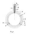
- Figure 1 shows a section through a container according to the teachings of the invention.
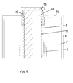
- Figure 2 shows an enlarged section through the spout of the invention Container.
- the container consists of an inner container 1, which receives the medium and a surrounding the inner container 1 outer housing. 2
- the container 1 and the housing 2 have the shape of a ball and are made of two hemispherical shells assembled. But there are others too Embodiments possible.
- the hemispherical shells are expediently made of austenitic steel and are connected by a weld.
- a thin-walled corrugated metal tube 3 is welded, which serves as a filling and pouring device.
- Concentric with the metal tube 3 is on the outer housing 2, a pipe socket. 4 arranged, which is also welded to the outer housing 2.
- Interspace 5 is filled with several layers 6 superinsulation and evacuated. Also the annular space 7 between the metal tube 3 and the pipe socket 4 has a plurality of layers Super insulation on. The vacuum space 5 is outwardly through an annular disc 14th sealed.
- the High temperature superconductors 8 are provided opposite two permanent magnets 9, which are attached to the outer housing 2.
- the high-temperature superconductor 8 and the Permanent magnets 9 ensure a contact-free storage of the inner container. 1 in the outer housing 2.
- a plug 10 made of insulating material, for. B. plastic provided whose diameter is almost equal to the clear width of the metal tube 3, so that the interior of the inner container 1 with the external environment by a helical channel 11 (see Figure 2) is connected through the vaporized Cold gas can escape.
- the enthalpy of the cold gas is fully utilized and the Heat inflow through the metal tube 3 into the interior of the container 1 is reduced.
- the vacuum space through the annular disc 14th sealed with the pipe socket 4 and one on the end of the metal tube. 3 screwed bushing 12 is gas-tight welded.
- the end of the metal tube 3 is also welded to the socket 12.
- the from the interior of the container. 1 Exiting cold gas can escape through an outlet 13 into the atmosphere.
- the wall thickness of the metal tube 3 is kept as low as possible. That's how it works Metal tube 3 made of a sheet of stainless steel by longitudinal seam welding and subsequent waves produced, the wall thickness is between 0.1 and 0.5 mm.
- the length of the metal tube 3 is between 30 and 200 mm, its outer diameter lies between
- the metal tube 3 has due to its small wall thickness and due to the Material of stainless steel a very low thermal conductivity. From the curl of the Metal tube 3 results in the advantage that the metal tube 3 a great deal of flexibility and has a higher transverse rigidity than a smooth metal tube. In addition, that is corrugated metal tube 3 "longer” than a smooth metal tube, because more metal band is required. Due to the larger "length", the thermal conductivity is again lower.
- the container according to the teachings of the invention is especially for liquefied gases suitable. Compared with commercial containers results in an extension of Liquefied gas storage by several factors.
Landscapes
- Engineering & Computer Science (AREA)
- Mechanical Engineering (AREA)
- General Engineering & Computer Science (AREA)
- Physics & Mathematics (AREA)
- Thermal Sciences (AREA)
- Filling Or Discharging Of Gas Storage Vessels (AREA)
- Blow-Moulding Or Thermoforming Of Plastics Or The Like (AREA)
Abstract
Description
- die automatische Aktivierung des Schwebezustands wird durch die flexible Halterung im Bereich der Ausgußöffnung erreicht,
- die Wärmeverluste im Bereich der Ausgußöffnung werden durch die Verwendung des schraubenlinienförmig gewellten Metallrohres reduziert. Durch den nichtmetallischen Stopfen wird das kalte verdampfte Gas in dem schraubenlinienförmig um die Ausgußöffnung herumlaufenden Strömungskanal entlanggeführt und erwärmt sich dort bis zum Austritt aus dem Ausguß. Dadurch wird die Enthalpie des Kaltgases voll ausgenutzt und die Wärmeeinströmung durch den Ausguß ins Innere des Behälters reduziert.
Claims (7)
- Doppelwandiger Behälter zur Lagerung und den Transport kryogener Medien, bestehend aus einem inneren, das Medium aufnehmenden Behälter sowie einem im Abstand zum inneren Behälter angeordneten Gehäuse und einem zwischen dem inneren Behälter und dem äußeren Gehäuse befindlichen Vakuumraum, wobei in dem Vakuumraum zumindest ein Permanentmagnet angeordnet ist und der Permanentmagnet und ein Hochtempertursupraleiter einander gegenüberliegen, so daß sich eine berührungslose Lagerung des inneren Behälters im Gehäuse ergibt, gekennzeichnet durch folgende Merkmale:der Hochtemperatursupraleiter (8) befindet sich im Vakuumraum (5),der innere Behälter (1) sowie das Gehäuse (2) weisen jeweils eine Aushalsung(3,4) auf, wobei die Aushalsungen (3,4) konzentrisch zueinander angeordnet
sind,die Aushalsung (3) des inneren Behälters (1) ist ein schraubenlinienförmig gewelltes Metallrohr (3), dessen nach außen weisendes Ende an der der
Aushalsung (4) Gehäuses (2) befestigt ist. - Behälter nach Anspruch 1, dadurch gekennzeichnet, daß der Permanentmagnet (9) am Gehäuse (2) und der Supraleiter (8) am inneren Behälter (1) befestigt ist.
- Behälter nach Anspruch 1 oder 2, dadurch gekennzeichnet, daß sich im Vakuumraum (5) mehrere Lagen (6) eines Superisolierwerkstoffs befinden.
- Behälter nach einem der Ansprüche 1 bis 3, dadurch gekennzeichnet, daß sich im Innern des gewellten Metallrohres (3) ein Stopfen (10) aus nicht metallischem Material befindet.
- Behälter nach Anspruch 4, dadurch gekennzeichnet, daß der Stopfen (10) den lichten Querschnitt des gewellten Metallrohres (3) ausfüllt, so daß ein schraubenlinienförmig verlaufender Kanal (11) zwischen Wellrohr (3) und Stopfen (10) gebildet wird.
- Behälter nach einem der Ansprüche 1 bis 5, dadurch gekennzeichnet, daß das Wellrohr (3) eine Wanddicke von 0,1 bis 0,5 mm aufweist.
- Behälter nach einem der Ansprüche 1 bis 6, dadurch gekennzeichnet, daß zwei oder mehrere Permanentmagneten (9) und Hochtemperatursupraleiter (8) im Winkel von 0 - 90° zur Senkrechten im Vakuumra um (5) gleichmäßig verteilt im unteren Behälterbereich angeordnet sind.
Priority Applications (6)
| Application Number | Priority Date | Filing Date | Title |
|---|---|---|---|
| AT04290556T ATE347069T1 (de) | 2004-03-01 | 2004-03-01 | Doppelwandiger behälter mit magnetischer aufhängung |
| EP04290556A EP1571390B1 (de) | 2004-03-01 | 2004-03-01 | Doppelwandiger Behälter mit magnetischer Aufhängung |
| DE502004002169T DE502004002169D1 (de) | 2004-03-01 | 2004-03-01 | Doppelwandiger Behälter mit magnetischer Aufhängung |
| US11/016,538 US7448511B2 (en) | 2004-03-01 | 2004-12-17 | Double-wall tank |
| KR1020050007945A KR20050088933A (ko) | 2004-03-01 | 2005-01-28 | 이중벽 탱크 |
| JP2005026895A JP2005249195A (ja) | 2004-03-01 | 2005-02-02 | 二重壁の容器 |
Applications Claiming Priority (1)
| Application Number | Priority Date | Filing Date | Title |
|---|---|---|---|
| EP04290556A EP1571390B1 (de) | 2004-03-01 | 2004-03-01 | Doppelwandiger Behälter mit magnetischer Aufhängung |
Publications (2)
| Publication Number | Publication Date |
|---|---|
| EP1571390A1 true EP1571390A1 (de) | 2005-09-07 |
| EP1571390B1 EP1571390B1 (de) | 2006-11-29 |
Family
ID=34746155
Family Applications (1)
| Application Number | Title | Priority Date | Filing Date |
|---|---|---|---|
| EP04290556A Expired - Lifetime EP1571390B1 (de) | 2004-03-01 | 2004-03-01 | Doppelwandiger Behälter mit magnetischer Aufhängung |
Country Status (6)
| Country | Link |
|---|---|
| US (1) | US7448511B2 (de) |
| EP (1) | EP1571390B1 (de) |
| JP (1) | JP2005249195A (de) |
| KR (1) | KR20050088933A (de) |
| AT (1) | ATE347069T1 (de) |
| DE (1) | DE502004002169D1 (de) |
Cited By (5)
| Publication number | Priority date | Publication date | Assignee | Title |
|---|---|---|---|---|
| WO2006034521A1 (de) * | 2004-09-30 | 2006-04-06 | Magna Steyr Fahrzeugtechnik Ag & Co. Kg | Tank für kryogene flüssigkeiten mit magnetischer aufhängung |
| EP3287685A1 (de) * | 2016-08-26 | 2018-02-28 | ABH Ingenieur-Technik GmbH | Thermobehälter für temperatursensible fluide |
| CN108072171A (zh) * | 2016-11-16 | 2018-05-25 | 北京北方华创微电子装备有限公司 | 气体管路的加热装置及半导体加工设备 |
| CN112730505A (zh) * | 2020-12-18 | 2021-04-30 | 上海交通大学 | 用于低温流体节流和定量测量的可视化实验舱 |
| GB2627008A (en) * | 2023-02-13 | 2024-08-14 | Zeroavia Ltd | Flux pinning superconducting LH2 tank |
Families Citing this family (11)
| Publication number | Priority date | Publication date | Assignee | Title |
|---|---|---|---|---|
| FR2893116B1 (fr) * | 2005-11-10 | 2009-11-20 | Air Liquide | Procede de production d'un reservoir et reservoir obtenu selon le procede |
| JP2010144843A (ja) * | 2008-12-19 | 2010-07-01 | Ud Trucks Corp | 液化ガス燃料容器 |
| KR101223492B1 (ko) * | 2010-10-22 | 2013-01-17 | 대우조선해양 주식회사 | 액화천연가스의 저장 용기 |
| US20140166662A1 (en) * | 2012-12-13 | 2014-06-19 | Hebeler Corporation | Suspension System for a Cryogenic Vessel |
| JP6134211B2 (ja) * | 2013-06-19 | 2017-05-24 | 川崎重工業株式会社 | 二重殻タンクおよび液化ガス運搬船 |
| CN107207233B (zh) * | 2014-09-08 | 2019-12-17 | 格绕乐威客股份公司 | 饮料分配器 |
| KR101732570B1 (ko) | 2015-09-25 | 2017-05-04 | 삼성중공업 주식회사 | 액화가스 저장탱크 |
| DE102017205279B3 (de) * | 2017-03-29 | 2018-09-20 | Bruker Biospin Ag | Kryostatanordnung mit einem Halsrohr mit einer tragenden Struktur und ein die tragende Struktur umgebendes Außenrohr zur Verringerung des Kryogenverbrauchs |
| JP7161293B2 (ja) * | 2018-03-02 | 2022-10-26 | 川崎重工業株式会社 | 二重殻タンクおよび液化ガス運搬船 |
| DE102021214273A1 (de) * | 2021-12-14 | 2023-06-15 | Festo Se & Co. Kg | Isoliereinrichtung sowie Verfahren zur Herstellung einer Isoliereinrichtung |
| EP4484819A1 (de) * | 2023-06-27 | 2025-01-01 | SAG Group B.V. | Behälter zur aufnahme eines kryofluids |
Citations (3)
| Publication number | Priority date | Publication date | Assignee | Title |
|---|---|---|---|---|
| GB2025029A (en) * | 1978-06-23 | 1980-01-16 | Boc Ltd | Vacuum Insulated Vessels or Conduits |
| US4750631A (en) * | 1986-07-21 | 1988-06-14 | Sperry Corporation | Anti-slosh apparatus for liquid containers |
| DE4418745A1 (de) * | 1994-05-28 | 1995-12-21 | Messer Griesheim Gmbh | Doppelwandiger isolierter Behälter |
Family Cites Families (13)
| Publication number | Priority date | Publication date | Assignee | Title |
|---|---|---|---|---|
| US2864591A (en) * | 1956-07-02 | 1958-12-16 | Calumet & Hecla | Corrugated tubing |
| US3358463A (en) * | 1966-07-15 | 1967-12-19 | Lockheed Aircraft Corp | Integrated superconducting magnetcryostat system |
| SU549147A1 (ru) * | 1973-10-25 | 1977-03-05 | Предприятие П/Я В-2572 | Сосуд дл хранени биопродуктов при низких температурах |
| US3948409A (en) * | 1974-11-12 | 1976-04-06 | Viktor Sergeevich Ovchinnikov | Cryostat |
| JPS5932758A (ja) * | 1982-08-16 | 1984-02-22 | 株式会社日立製作所 | 冷凍機付クライオスタツト |
| US4496073A (en) * | 1983-02-24 | 1985-01-29 | The Johns Hopkins University | Cryogenic tank support system |
| JPS6020591A (ja) * | 1983-07-14 | 1985-02-01 | Toshiba Corp | 極低温冷媒移送管 |
| JPS6117798A (ja) * | 1984-07-04 | 1986-01-25 | Kawasaki Heavy Ind Ltd | 二重殻断熱容器 |
| JPH01277185A (ja) * | 1988-04-27 | 1989-11-07 | Nec Home Electron Ltd | 断熱容器 |
| US4986078A (en) * | 1989-08-17 | 1991-01-22 | General Electric Company | Refrigerated MR magnet support system |
| JPH05223424A (ja) * | 1992-02-12 | 1993-08-31 | Sumitomo Electric Ind Ltd | 極低温容器 |
| JPH05280698A (ja) * | 1992-03-30 | 1993-10-26 | Nippon Ferrofluidics Kk | 低温物質の保存装置 |
| GB2425345B (en) * | 2002-11-21 | 2007-03-14 | Ge Med Sys Global Tech Co Llc | Cryogen pressure vessel assembly for superconducting magnets |
-
2004
- 2004-03-01 DE DE502004002169T patent/DE502004002169D1/de not_active Expired - Fee Related
- 2004-03-01 EP EP04290556A patent/EP1571390B1/de not_active Expired - Lifetime
- 2004-03-01 AT AT04290556T patent/ATE347069T1/de not_active IP Right Cessation
- 2004-12-17 US US11/016,538 patent/US7448511B2/en not_active Expired - Fee Related
-
2005
- 2005-01-28 KR KR1020050007945A patent/KR20050088933A/ko not_active Withdrawn
- 2005-02-02 JP JP2005026895A patent/JP2005249195A/ja active Pending
Patent Citations (3)
| Publication number | Priority date | Publication date | Assignee | Title |
|---|---|---|---|---|
| GB2025029A (en) * | 1978-06-23 | 1980-01-16 | Boc Ltd | Vacuum Insulated Vessels or Conduits |
| US4750631A (en) * | 1986-07-21 | 1988-06-14 | Sperry Corporation | Anti-slosh apparatus for liquid containers |
| DE4418745A1 (de) * | 1994-05-28 | 1995-12-21 | Messer Griesheim Gmbh | Doppelwandiger isolierter Behälter |
Cited By (7)
| Publication number | Priority date | Publication date | Assignee | Title |
|---|---|---|---|---|
| WO2006034521A1 (de) * | 2004-09-30 | 2006-04-06 | Magna Steyr Fahrzeugtechnik Ag & Co. Kg | Tank für kryogene flüssigkeiten mit magnetischer aufhängung |
| EP3287685A1 (de) * | 2016-08-26 | 2018-02-28 | ABH Ingenieur-Technik GmbH | Thermobehälter für temperatursensible fluide |
| CN108072171A (zh) * | 2016-11-16 | 2018-05-25 | 北京北方华创微电子装备有限公司 | 气体管路的加热装置及半导体加工设备 |
| CN112730505A (zh) * | 2020-12-18 | 2021-04-30 | 上海交通大学 | 用于低温流体节流和定量测量的可视化实验舱 |
| CN112730505B (zh) * | 2020-12-18 | 2022-05-17 | 上海交通大学 | 用于低温流体节流和定量测量的可视化实验舱 |
| GB2627008A (en) * | 2023-02-13 | 2024-08-14 | Zeroavia Ltd | Flux pinning superconducting LH2 tank |
| GB2627008B (en) * | 2023-02-13 | 2025-04-30 | Zeroavia Ltd | Flux pinning superconducting LH2 tank |
Also Published As
| Publication number | Publication date |
|---|---|
| ATE347069T1 (de) | 2006-12-15 |
| JP2005249195A (ja) | 2005-09-15 |
| US7448511B2 (en) | 2008-11-11 |
| EP1571390B1 (de) | 2006-11-29 |
| DE502004002169D1 (de) | 2007-01-11 |
| KR20050088933A (ko) | 2005-09-07 |
| US20050211710A1 (en) | 2005-09-29 |
Similar Documents
| Publication | Publication Date | Title |
|---|---|---|
| EP1571390B1 (de) | Doppelwandiger Behälter mit magnetischer Aufhängung | |
| EP1287285B1 (de) | Speicherbehälter für kryogenen treibstoff | |
| EP1128123B1 (de) | Speicherbehälter für kryogene Flüssigkeiten mit verstärkten Wandungen | |
| EP1736715A1 (de) | Vakuumröhren für Solarkollektoren mit verbessertem Wärmeübergang | |
| EP0319458A2 (de) | Druckbehälter für die Speicherung von Wasserstoff | |
| DE102015222392A1 (de) | Druckbehälter mit einem Lastring, Kraftfahrzeug und Verfahren zur Herstellung eines Druckbehälters | |
| DE1931749B2 (de) | Zylindrischer tank zur aufnahme tiefsiedender verfluessigter gase | |
| DE202005006024U1 (de) | Super-Vakuum-Isolationstank für Tieftemperatur-Flüssiggas | |
| WO2017080724A1 (de) | Druckbehälter mit einer domkappe und verfahren zur herstellung eines druckbehälters | |
| WO2016087233A1 (de) | Kryogener druckbehälter | |
| DE202013101162U1 (de) | Tank für kryogene Fluide | |
| AT505660A4 (de) | Behälter zur aufnahme eines fluids | |
| DE102016206994A1 (de) | Kryogen betankbarer Hochdruckgasbehälter | |
| DE2148963A1 (de) | Behaelter fuer Kaeltemittel | |
| DE19816651C2 (de) | Speicheranordnung für tiefkalte Fluide | |
| DE1951370A1 (de) | Lagerbehaelter fuer bei niedriger Temperatur fluessige Gase | |
| DE10148587C1 (de) | Isolierende Komponente für wechselbar temperierfähiges Behältnis | |
| DE202005006022U1 (de) | Stützstruktur eines Super-Vakuum-Isolationstanks für Tieftemperatur-Flüssiggas | |
| EP1457729B1 (de) | Abstandshalter für ein langgestrecktes Substrat | |
| DE202005006034U1 (de) | Umgekehrt-kuppelförmiges Ende eines Super-Vakuum-Isolationstanks für Tieftemperatur-Flüssiggas | |
| WO1991019931A1 (de) | Grossbehälter zur lagerung oder zum transport verflüssigter gase | |
| EP1131580B1 (de) | Rohrförmige konstruktion | |
| EP4609104A1 (de) | Wärmeisoliertes erzeugnis | |
| DE4418745A1 (de) | Doppelwandiger isolierter Behälter | |
| AT4636U1 (de) | Rohrartige leitung oder behälter zum transport bzw. zum aufbewahren kryogener medien |
Legal Events
| Date | Code | Title | Description |
|---|---|---|---|
| PUAI | Public reference made under article 153(3) epc to a published international application that has entered the european phase |
Free format text: ORIGINAL CODE: 0009012 |
|
| 17P | Request for examination filed |
Effective date: 20040728 |
|
| AK | Designated contracting states |
Kind code of ref document: A1 Designated state(s): AT BE BG CH CY CZ DE DK EE ES FI FR GB GR HU IE IT LI LU MC NL PL PT RO SE SI SK TR |
|
| AX | Request for extension of the european patent |
Extension state: AL LT LV MK |
|
| AKX | Designation fees paid |
Designated state(s): AT BE BG CH CY CZ DE DK EE ES FI FR GB GR HU IE IT LI LU MC NL PL PT RO SE SI SK TR |
|
| GRAP | Despatch of communication of intention to grant a patent |
Free format text: ORIGINAL CODE: EPIDOSNIGR1 |
|
| GRAS | Grant fee paid |
Free format text: ORIGINAL CODE: EPIDOSNIGR3 |
|
| GRAA | (expected) grant |
Free format text: ORIGINAL CODE: 0009210 |
|
| AK | Designated contracting states |
Kind code of ref document: B1 Designated state(s): AT BE BG CH CY CZ DE DK EE ES FI FR GB GR HU IE IT LI LU MC NL PL PT RO SE SI SK TR |
|
| PG25 | Lapsed in a contracting state [announced via postgrant information from national office to epo] |
Ref country code: CZ Free format text: LAPSE BECAUSE OF FAILURE TO SUBMIT A TRANSLATION OF THE DESCRIPTION OR TO PAY THE FEE WITHIN THE PRESCRIBED TIME-LIMIT Effective date: 20061129 Ref country code: SK Free format text: LAPSE BECAUSE OF FAILURE TO SUBMIT A TRANSLATION OF THE DESCRIPTION OR TO PAY THE FEE WITHIN THE PRESCRIBED TIME-LIMIT Effective date: 20061129 Ref country code: RO Free format text: LAPSE BECAUSE OF FAILURE TO SUBMIT A TRANSLATION OF THE DESCRIPTION OR TO PAY THE FEE WITHIN THE PRESCRIBED TIME-LIMIT Effective date: 20061129 Ref country code: NL Free format text: LAPSE BECAUSE OF FAILURE TO SUBMIT A TRANSLATION OF THE DESCRIPTION OR TO PAY THE FEE WITHIN THE PRESCRIBED TIME-LIMIT Effective date: 20061129 Ref country code: FI Free format text: LAPSE BECAUSE OF FAILURE TO SUBMIT A TRANSLATION OF THE DESCRIPTION OR TO PAY THE FEE WITHIN THE PRESCRIBED TIME-LIMIT Effective date: 20061129 Ref country code: SI Free format text: LAPSE BECAUSE OF FAILURE TO SUBMIT A TRANSLATION OF THE DESCRIPTION OR TO PAY THE FEE WITHIN THE PRESCRIBED TIME-LIMIT Effective date: 20061129 Ref country code: PL Free format text: LAPSE BECAUSE OF FAILURE TO SUBMIT A TRANSLATION OF THE DESCRIPTION OR TO PAY THE FEE WITHIN THE PRESCRIBED TIME-LIMIT Effective date: 20061129 Ref country code: IE Free format text: LAPSE BECAUSE OF FAILURE TO SUBMIT A TRANSLATION OF THE DESCRIPTION OR TO PAY THE FEE WITHIN THE PRESCRIBED TIME-LIMIT Effective date: 20061129 |
|
| REG | Reference to a national code |
Ref country code: GB Ref legal event code: FG4D Free format text: NOT ENGLISH |
|
| REG | Reference to a national code |
Ref country code: CH Ref legal event code: EP |
|
| GBT | Gb: translation of ep patent filed (gb section 77(6)(a)/1977) |
Effective date: 20061219 |
|
| REG | Reference to a national code |
Ref country code: IE Ref legal event code: FG4D Free format text: LANGUAGE OF EP DOCUMENT: GERMAN |
|
| REF | Corresponds to: |
Ref document number: 502004002169 Country of ref document: DE Date of ref document: 20070111 Kind code of ref document: P |
|
| REG | Reference to a national code |
Ref country code: CH Ref legal event code: NV Representative=s name: CRONIN INTELLECTUAL PROPERTY |
|
| PG25 | Lapsed in a contracting state [announced via postgrant information from national office to epo] |
Ref country code: DK Free format text: LAPSE BECAUSE OF FAILURE TO SUBMIT A TRANSLATION OF THE DESCRIPTION OR TO PAY THE FEE WITHIN THE PRESCRIBED TIME-LIMIT Effective date: 20070228 Ref country code: BG Free format text: LAPSE BECAUSE OF FAILURE TO SUBMIT A TRANSLATION OF THE DESCRIPTION OR TO PAY THE FEE WITHIN THE PRESCRIBED TIME-LIMIT Effective date: 20070228 Ref country code: SE Free format text: LAPSE BECAUSE OF FAILURE TO SUBMIT A TRANSLATION OF THE DESCRIPTION OR TO PAY THE FEE WITHIN THE PRESCRIBED TIME-LIMIT Effective date: 20070228 |
|
| PG25 | Lapsed in a contracting state [announced via postgrant information from national office to epo] |
Ref country code: ES Free format text: LAPSE BECAUSE OF FAILURE TO SUBMIT A TRANSLATION OF THE DESCRIPTION OR TO PAY THE FEE WITHIN THE PRESCRIBED TIME-LIMIT Effective date: 20070312 |
|
| REG | Reference to a national code |
Ref country code: CH Ref legal event code: PCAR Free format text: CRONIN INTELLECTUAL PROPERTY;CHEMIN DE PRECOSSY 31;1260 NYON (CH) |
|
| PG25 | Lapsed in a contracting state [announced via postgrant information from national office to epo] |
Ref country code: PT Free format text: LAPSE BECAUSE OF FAILURE TO SUBMIT A TRANSLATION OF THE DESCRIPTION OR TO PAY THE FEE WITHIN THE PRESCRIBED TIME-LIMIT Effective date: 20070430 |
|
| ET | Fr: translation filed | ||
| NLV1 | Nl: lapsed or annulled due to failure to fulfill the requirements of art. 29p and 29m of the patents act | ||
| REG | Reference to a national code |
Ref country code: IE Ref legal event code: FD4D |
|
| PLBE | No opposition filed within time limit |
Free format text: ORIGINAL CODE: 0009261 |
|
| STAA | Information on the status of an ep patent application or granted ep patent |
Free format text: STATUS: NO OPPOSITION FILED WITHIN TIME LIMIT |
|
| 26N | No opposition filed |
Effective date: 20070830 |
|
| BERE | Be: lapsed |
Owner name: NEXANS Effective date: 20070331 |
|
| PG25 | Lapsed in a contracting state [announced via postgrant information from national office to epo] |
Ref country code: BE Free format text: LAPSE BECAUSE OF NON-PAYMENT OF DUE FEES Effective date: 20070331 |
|
| PG25 | Lapsed in a contracting state [announced via postgrant information from national office to epo] |
Ref country code: MC Free format text: LAPSE BECAUSE OF NON-PAYMENT OF DUE FEES Effective date: 20070331 |
|
| PG25 | Lapsed in a contracting state [announced via postgrant information from national office to epo] |
Ref country code: GR Free format text: LAPSE BECAUSE OF FAILURE TO SUBMIT A TRANSLATION OF THE DESCRIPTION OR TO PAY THE FEE WITHIN THE PRESCRIBED TIME-LIMIT Effective date: 20070301 |
|
| PG25 | Lapsed in a contracting state [announced via postgrant information from national office to epo] |
Ref country code: AT Free format text: LAPSE BECAUSE OF NON-PAYMENT OF DUE FEES Effective date: 20070301 |
|
| PG25 | Lapsed in a contracting state [announced via postgrant information from national office to epo] |
Ref country code: EE Free format text: LAPSE BECAUSE OF FAILURE TO SUBMIT A TRANSLATION OF THE DESCRIPTION OR TO PAY THE FEE WITHIN THE PRESCRIBED TIME-LIMIT Effective date: 20061129 |
|
| PGFP | Annual fee paid to national office [announced via postgrant information from national office to epo] |
Ref country code: CH Payment date: 20090316 Year of fee payment: 6 Ref country code: GB Payment date: 20090325 Year of fee payment: 6 |
|
| PG25 | Lapsed in a contracting state [announced via postgrant information from national office to epo] |
Ref country code: CY Free format text: LAPSE BECAUSE OF FAILURE TO SUBMIT A TRANSLATION OF THE DESCRIPTION OR TO PAY THE FEE WITHIN THE PRESCRIBED TIME-LIMIT Effective date: 20061129 Ref country code: LU Free format text: LAPSE BECAUSE OF NON-PAYMENT OF DUE FEES Effective date: 20070301 |
|
| PGFP | Annual fee paid to national office [announced via postgrant information from national office to epo] |
Ref country code: DE Payment date: 20090320 Year of fee payment: 6 Ref country code: IT Payment date: 20090321 Year of fee payment: 6 |
|
| PG25 | Lapsed in a contracting state [announced via postgrant information from national office to epo] |
Ref country code: TR Free format text: LAPSE BECAUSE OF FAILURE TO SUBMIT A TRANSLATION OF THE DESCRIPTION OR TO PAY THE FEE WITHIN THE PRESCRIBED TIME-LIMIT Effective date: 20061129 Ref country code: HU Free format text: LAPSE BECAUSE OF FAILURE TO SUBMIT A TRANSLATION OF THE DESCRIPTION OR TO PAY THE FEE WITHIN THE PRESCRIBED TIME-LIMIT Effective date: 20070530 |
|
| PGFP | Annual fee paid to national office [announced via postgrant information from national office to epo] |
Ref country code: FR Payment date: 20090312 Year of fee payment: 6 |
|
| REG | Reference to a national code |
Ref country code: CH Ref legal event code: PL |
|
| GBPC | Gb: european patent ceased through non-payment of renewal fee |
Effective date: 20100301 |
|
| REG | Reference to a national code |
Ref country code: FR Ref legal event code: ST Effective date: 20101130 |
|
| PG25 | Lapsed in a contracting state [announced via postgrant information from national office to epo] |
Ref country code: FR Free format text: LAPSE BECAUSE OF NON-PAYMENT OF DUE FEES Effective date: 20100331 |
|
| PG25 | Lapsed in a contracting state [announced via postgrant information from national office to epo] |
Ref country code: DE Free format text: LAPSE BECAUSE OF NON-PAYMENT OF DUE FEES Effective date: 20101001 Ref country code: CH Free format text: LAPSE BECAUSE OF NON-PAYMENT OF DUE FEES Effective date: 20100331 Ref country code: LI Free format text: LAPSE BECAUSE OF NON-PAYMENT OF DUE FEES Effective date: 20100331 |
|
| PG25 | Lapsed in a contracting state [announced via postgrant information from national office to epo] |
Ref country code: IT Free format text: LAPSE BECAUSE OF NON-PAYMENT OF DUE FEES Effective date: 20100301 Ref country code: GB Free format text: LAPSE BECAUSE OF NON-PAYMENT OF DUE FEES Effective date: 20100301 |