EP1571122A1 - Dispensing valve - Google Patents
Dispensing valve Download PDFInfo
- Publication number
- EP1571122A1 EP1571122A1 EP05004649A EP05004649A EP1571122A1 EP 1571122 A1 EP1571122 A1 EP 1571122A1 EP 05004649 A EP05004649 A EP 05004649A EP 05004649 A EP05004649 A EP 05004649A EP 1571122 A1 EP1571122 A1 EP 1571122A1
- Authority
- EP
- European Patent Office
- Prior art keywords
- dispensing valve
- outlet
- open position
- valve member
- valve
- Prior art date
- Legal status (The legal status is an assumption and is not a legal conclusion. Google has not performed a legal analysis and makes no representation as to the accuracy of the status listed.)
- Granted
Links
Images

Classifications
-
- B—PERFORMING OPERATIONS; TRANSPORTING
- B67—OPENING, CLOSING OR CLEANING BOTTLES, JARS OR SIMILAR CONTAINERS; LIQUID HANDLING
- B67D—DISPENSING, DELIVERING OR TRANSFERRING LIQUIDS, NOT OTHERWISE PROVIDED FOR
- B67D3/00—Apparatus or devices for controlling flow of liquids under gravity from storage containers for dispensing purposes
- B67D3/04—Liquid-dispensing taps or cocks adapted to seal and open tapping holes of casks, e.g. for beer
- B67D3/045—Liquid-dispensing taps or cocks adapted to seal and open tapping holes of casks, e.g. for beer with a closing element having a linear movement, in a direction parallel to the seat
- B67D3/046—Liquid-dispensing taps or cocks adapted to seal and open tapping holes of casks, e.g. for beer with a closing element having a linear movement, in a direction parallel to the seat and venting means operated automatically with the tap
Definitions
- the invention relates to a dispensing valve for a flowable medium containing Container, with a movable in an open position valve member, in a rest position holding an outlet closed, as well as one with such a dispensing valve provided container.
- Such dispensing valves are arranged in a closure element of the container opening, into which they are generally inserted and fixed after filling. To the To be able to remove container contents in particular in portions, the valve member is in the Open position moves, for which different possibilities are given.
- valve part can be twisted.
- An example of a metering device with a rotatable valve member shows the WO 99/18026 or US 5,715,877.
- valve member can be moved axially.
- An example of a metering device with an axially displaceable valve member WO 93/13009.
- the valve part can be twisted and moved axially.
- An example of one Dosing device with such a valve member is shown in WO 01/28914.
- the valve When the valve is open, a certain amount of the medium flows out, with the Amount depends on the opening cross-section of the opening time, for example from the Duration of actuation of a corresponding handle.
- the invention now provides a dispensing valve by means of which optionally at least two different quantities per unit of time can be removed from the container, by the dispensing valve at least two open positions with different Having outlet cross sections.
- the dispensing valve is preferably assigned an actuating handle per open position, so that the valve part is transferred into the respective open position by selecting the handle.
- each of the three above is indicated Possibilities conceivable.
- the valve member is height adjustable, and the both open positions are provided one above the other. At the higher level the valve member are thus successively achieved the individual open positions, wherein the Order in itself is not important.
- the Valve part after a short opening stroke in the first open position a small Outlet cross section and after a longer opening path in the second open position the larger outlet cross-section releases.
- Each outlet cross section is determined in particular by discrete outlet openings which are provided successively in the opening path.
- a first outlet opening When in the first open position, a first outlet opening, and in the second Open position, a second outlet opening is open, so are two different Possibilities given.
- the first outlet opening remain open, so that the larger outlet cross-section results from the sum of the two outlet openings, wherein the second outlet opening may be smaller, equal or larger, as they are in any case the first outlet is added.
- the first outlet opening is closed again when the second one is opened becomes.
- the second exit opening is larger, if preferred as above indicated, the second outlet opening the larger outlet cross-section, and smaller, if the first outlet opening should have the larger outlet cross-section.
- a preferred embodiment of the dispensing valve provides that the dispensing valve a In the container opening usable hollow cylindrical closure element, in which the movable valve member is guided piston-like sealing, and that the outlet openings by at least two axially offset holes in a side wall of the closure element are formed, which in the stroke of the valve member, the container interior with the environment flow-connect. If the container is not flexible, but essentially Having rigid walls, it is further provided that the valve member has an axial Air inlet channel has.
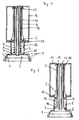
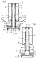
- FIGS. 1 to 4 each show axial sections through a dispensing valve inserted into an upright container, FIG. 1 showing the closed or inoperative position, FIG. 2 showing a first open position, FIG. 3 showing a second open position and FIG. 4 a third Open position is visible, and Fig. 5 and 6 axial sections according to FIGS. 1 and 4 by a second embodiment.
- a discharge valve 2 has a cross-section of the opening of a container 1 adapted closure element 4, which after filling the container 1 with a flowable medium, such as a cleaning or disinfectant concentrate inserted into the container opening and permanently fixed, e.g. glued or welded, is.
- the closure element 4 is projecting with a into the interior of the container 1 Pipe section 5 provided, which via a convergent guide part 3 in a Pipe section 6 passes, which has a smaller diameter than the pipe section. 5 having.
- the pipe section 5 has in the embodiment shown three superimposed Outlet openings 7, 8. 9 on.
- a piston-like valve member 10 extends in the closed position according to Fig. 1 or 5 in an outermost position in which a flow connection between the interior of the container 1 through the outlet openings 7, 8, 9 to the outside is interrupted.
- a compression spring 16 is provided, which urges the valve member 10 in the closed position.
- the piston-like valve member 10 has an inwardly extending air inlet tube 11, which is guided centrally in the pipe section 6 at a distance therefrom.
- At the bottom of the Lucaseinholrohres 11 may be formed an annular sealing edge 20, as Fig. 5 shows.
- the cover 12 includes a certain volume of air and prevents the flowable medium can penetrate into the air inlet tube 11.
- holes 15 are provided in the upper end region.
- Fig. 1 to 4 is in the interior of the inlet pipe 11 via not shown Webs another tube 14 held on the side of the valve member 10 slightly out of the Inlet tube 11 protrudes and ends at a small distance to the cover 12:
- the other Pipe 14 causes a division of the incoming air into two channels, so that even then, when flowable medium enters the air inlet tube 11, ventilation over the another tube 14 can take place.
- this further tube is missing, since the penetration of flowable medium through the annular gap between the pipe section 6 of the Closing element 4 and the air inlet tube 11 by an approximately centrally disposed Sealing ring 21 is prevented.
- Fig. 4 and 6 shows a third Open position in which the valve member 10 is raised even higher, so that all the top Exiting outlets 9.
- the flowable medium can thus through all three openings 7, 8, 9 in a correspondingly large amount per unit time through the pipe section 5 after flow out at the bottom, wherein at the lower end of the pipe section 5 in the embodiment of FIG. 5 and 6, an annular Abtropfhaube 19 is formed.
- Which receive the spring 16 Room 18, as shown in FIGS. 5 and 6, may be associated with a vent opening 17, around which to be displaced when lifting the valve member 10 to be displaced air.
Abstract
Description
Die Erfindung betrifft ein Ausgabeventil für einen ein fließfähiges Medium enthaltenden Behälter, mit einem in eine Offenstellung bewegbaren Ventilteil, der in einer Ruhestellung einen Auslass verschlossen hält, sowie einen mit einem derartigen Ausgabeventil versehenen Behälter.The invention relates to a dispensing valve for a flowable medium containing Container, with a movable in an open position valve member, in a rest position holding an outlet closed, as well as one with such a dispensing valve provided container.
Derartige Ausgabeventile sind in einem Verschlusselement der Behälteröffnung angeordnet, in die sie im Allgemeinen nach der Füllung eingesetzt und fixiert werden. Um den Behälterinhalt insbesondere portionsweise entnehmen zu können, wird der Ventilteil in die Offenstellung bewegt, wofür verschiedene Möglichkeiten gegeben sind.Such dispensing valves are arranged in a closure element of the container opening, into which they are generally inserted and fixed after filling. To the To be able to remove container contents in particular in portions, the valve member is in the Open position moves, for which different possibilities are given.
Der Ventilteil kann verdreht werden. Ein Beispiel für eine Dosiereinrichtung mit einem verdrehbaren Ventilteil zeigt die WO 99/18026 oder die US 5,715,877.The valve part can be twisted. An example of a metering device with a rotatable valve member shows the WO 99/18026 or US 5,715,877.
Der Ventilteil kann axial verschoben werden. Ein Beispiel für eine Dosiereinrichtung mit einem axial verschiebbaren Ventilteil zeigt die WO 93/13009.The valve member can be moved axially. An example of a metering device with an axially displaceable valve member, WO 93/13009.
Der Ventilteil kann verdreht und axial verschoben werden. Ein Beispiel für eine Dosiereinrichtung mit einem derartigen Ventilteil zeigt die WO 01/28914.The valve part can be twisted and moved axially. An example of one Dosing device with such a valve member is shown in WO 01/28914.
Wenn das Ventil geöffnet ist, so fließt eine bestimmte Menge des Mediums aus, wobei die Menge vom Öffnungsquerschnitt von der Öffnungszeit abhängt, beispielsweise von der Dauer der Betätigung einer entsprechenden Handhabe.When the valve is open, a certain amount of the medium flows out, with the Amount depends on the opening cross-section of the opening time, for example from the Duration of actuation of a corresponding handle.
Die Erfindung stellt nun ein Ausgabeventil zur Verfügung, mittels dem wahlweise zumindest zwei unterschiedliche Mengen pro Zeiteinheit aus dem Behälter entnommen werden können, indem das Ausgabeventil zumindest zwei Offenstellungen mit unterschiedlichen Auslassquerschnitten aufweist.The invention now provides a dispensing valve by means of which optionally at least two different quantities per unit of time can be removed from the container, by the dispensing valve at least two open positions with different Having outlet cross sections.
Dem Ausgabeventil ist bevorzugt pro Offenstellung eine Betätigungshandhabe zugeordnet, sodass durch Wahl der Handhabe der Ventilteil in die jeweilige Offenstellung überführt wird.The dispensing valve is preferably assigned an actuating handle per open position, so that the valve part is transferred into the respective open position by selecting the handle.
Für die Überführung in die Offenstellungen ist jede der drei oben angegebenen Möglichkeiten denkbar. Wird der Behälter kopfstehend in eine Dosiervorrichtung eingesetzt, so ist in bevorzugter Ausführung vorgesehen, dass der Ventilteil höhenverstellbar ist, und die beiden Offenstellungen übereinander vorgesehen sind. Bei der Höheriverstellung des Ventilteiles werden somit nacheinander die einzelnen Offenstellungen erreicht, wobei die Reihenfolge an sich nicht von Bedeutung ist. Bevorzugt ist jedoch vorgesehen, dass der Ventilteil nach einem kurzen Öffnungsweg in der ersten Offenstellung einen kleinen Auslassquerschnitt und nach einem längeren Öffnungsweg in der zweiten Offenstellung den größeren Auslassquerschnitt freigibt.For the transfer to the open positions, each of the three above is indicated Possibilities conceivable. If the container is placed inverted in a dosing device, it is provided in a preferred embodiment, that the valve member is height adjustable, and the both open positions are provided one above the other. At the higher level the valve member are thus successively achieved the individual open positions, wherein the Order in itself is not important. However, it is preferably provided that the Valve part after a short opening stroke in the first open position a small Outlet cross section and after a longer opening path in the second open position the larger outlet cross-section releases.
Jeder Auslassquerschnitt wird insbesondere durch diskrete Austrittsöffnungen bestimmt, die nacheinander im Öffnungsweg vorgesehen sind. Dies bietet den Vorteil, dass die aus dem Behälter austretende Menge nicht von der präzisen Handhabung des Ventilteils abhängig ist, sodass Ungenauigkeiten aller Art, etwa bei der Herstellung des Ausgabeventils, bei der Herstellung des Behälters, in der Betätigungsmechanik der Dosiereinrichtung, usw. keine Auswirkungen auf die dosierte Menge aufweisen. Die jeweilige Weglänge bis zur Freigabe der entsprechenden Austrittsöffnung ist eher unkritisch.Each outlet cross section is determined in particular by discrete outlet openings which are provided successively in the opening path. This offers the advantage that the from the Container escaping quantity is not dependent on the precise handling of the valve member, so inaccuracies of all kinds, such as in the production of the dispensing valve, in the Production of the container, in the actuating mechanism of the metering device, etc. no Have effects on the metered amount. The respective path length until release the corresponding outlet is rather uncritical.
Bei der durchaus denkbaren Möglichkeit, dass sich der Auslassquerschnitt durch die Bewegung des Ventilteils kontinuierlich vergrößert, ist dieser Spielraum nicht gegeben. In einer derartigen Ausführung ist dann vorzugsweise eine Justiereinrichtung vorgesehen.In the quite conceivable possibility that the outlet cross section through the Movement of the valve member increases continuously, this margin is not given. In Such an embodiment is then preferably provided an adjusting device.
Wenn in der ersten Offenstellung eine erste Austrittsöffnung, und in der zweiten Offenstellung eine zweite Austrittsöffnung geöffnet ist, so sind zwei verschiedene Möglichkeiten gegeben. Zum Einen kann die erste Austrittsöffnung geöffnet bleiben, sodass der größere Auslassquerschnitt sich aus der Summe der beiden Austrittsöffnungen ergibt, wobei die zweite Austrittsöffnung kleiner, gleich oder größer sein kann, da sie in jedem Fall die erste Austrittsöffnung ergänzt.When in the first open position, a first outlet opening, and in the second Open position, a second outlet opening is open, so are two different Possibilities given. On the one hand, the first outlet opening remain open, so that the larger outlet cross-section results from the sum of the two outlet openings, wherein the second outlet opening may be smaller, equal or larger, as they are in any case the first outlet is added.
Im zweiten Fall wird die erste Austrittsöffnung wieder verschlossen, wenn die zweite geöffnet wird. In diesem Fall ist die zweite Austrittsöffnung größer, wenn wie oben bevorzugt angegeben, die zweite Austrittsöffnung den größeren Auslassquerschnitt, und kleiner, wenn die erste Austrittsöffnung den größeren Auslassquerschnitt aufweisen soll.In the second case, the first outlet opening is closed again when the second one is opened becomes. In this case, the second exit opening is larger, if preferred as above indicated, the second outlet opening the larger outlet cross-section, and smaller, if the first outlet opening should have the larger outlet cross-section.
Eine bevorzugte Ausführungsform des Ausgabeventils sieht vor, dass das Ausgabeventil ein in die Behälteröffnung einsetzbares hohlzylindrisches Verschlusselement aufweist, in dem der bewegbare Ventilteil kolbenartig dichtend geführt ist, und dass die Austrittsöffnungen durch zumindest zwei axial versetzte Löcher in einer Seitenwand des Verschlusselementes gebildet sind, die beim Hub des Ventilteils das Behälterinnere mit der Umgebung strömungsverbinden. Wenn der Behälter keine flexiblen, sondern im Wesentlichen steife Wandungen aufweist, so ist weiters vorgesehen, dass der Ventilteil einen axialen Lufteinlasskanal aufweist.A preferred embodiment of the dispensing valve provides that the dispensing valve a In the container opening usable hollow cylindrical closure element, in which the movable valve member is guided piston-like sealing, and that the outlet openings by at least two axially offset holes in a side wall of the closure element are formed, which in the stroke of the valve member, the container interior with the environment flow-connect. If the container is not flexible, but essentially Having rigid walls, it is further provided that the valve member has an axial Air inlet channel has.
Nachstehend werden zwei Ausführungsbeispiele der Erfindung an Hand der Figuren der beiliegenden Zeichnung näher beschrieben, ohne darauf beschränkt zu sein.Hereinafter, two embodiments of the invention with reference to the figures of attached to the accompanying drawings, without being limited thereto.
Es zeigen:
Die Fig. 1 bis 4 jeweils Axialschnitte durch ein in einen kopfstehenden Behälter eingesetztes
Ausgabeventil, wobei aus Fig. 1 die Schließ- oder Ruhestellung, aus Fig. 2 eine erste
Offenstellung, aus Fig. 3 eine zweite Offenstellung und aus Fig. 4 eine dritte Offenstellung
ersichtlich ist, und Fig. 5 und 6 Axialschnitte gemäß Fig. 1 und 4 durch ein zweites
Ausführungsbeispiel.Show it:
FIGS. 1 to 4 each show axial sections through a dispensing valve inserted into an upright container, FIG. 1 showing the closed or inoperative position, FIG. 2 showing a first open position, FIG. 3 showing a second open position and FIG. 4 a third Open position is visible, and Fig. 5 and 6 axial sections according to FIGS. 1 and 4 by a second embodiment.
Ein Ausgabeventil 2 weist ein an den Querschnitt der Öffnung eines Behälters 1
angepasstes Verschlusselement 4 auf, das nach der Befüllung des Behälters 1 mit einem
fließfähigen Medium, beispielsweise einem Reinigungs- oder Desinfektionsmittelkonzentrat
in die Behälteröffnung eingesetzt und dauerhaft fixiert, z.B. verklebt oder verschweißt, wird.
Das Verschlusselement 4 ist mit einem in das Innere des Behälters 1 ragenden
Rohrabschnitt 5 versehen, der über einen konvergierenden Führungsteil 3 in einen
Rohrabschnitt 6 übergeht, der einen kleineren Durchmesser als der Rohrabschnitt 5
aufweist.A
Der Rohrabschnitt 5 weist im gezeigten Ausführungsbeispiel drei übereinander angeordnete
Austrittsöffnungen 7, 8. 9 auf. Ein kolbenartiger Ventilteil 10 erstreckt sich in der Schließstellung
nach Fig. 1 oder 5 in einer äußersten Position, in der eine Strömungsverbindung
zwischen dem Inneren des Behälters 1 durch die Austrittsöffnungen 7, 8, 9 nach außen
unterbrochen ist. Zwischen dem Ventilteil 10 und dem konvergierenden Führungsteil 3 ist
eine Druckfeder 16 vorgesehen, die den Ventilteil 10 in die Schließstellung beaufschlagt.The
Der kolbenartige Ventilteil 10 weist ein sich nach innen erstreckendes Lufteinlassrohr 11 auf,
das mittig im Rohrabschnitt 6 mit Abstand dazu geführt ist. In der gezeigten Ausführung für
kopfstehende Behälter ist auf das innere Ende des Lufteinlassrohres 11 eine topfartige
Abdeckung 12 aufgesetzt, die einen unteren Zentrierring 13 aufweist. Am unteren Ende des
Lufteinfassrohres 11 kann eine ringförmige Dichtkante 20 ausgebildet sein, wie Fig. 5 zeigt. The piston-
Die Abdeckung 12 umfasst ein bestimmtes Luftvolumen und verhindert, dass das
fließfähige Medium in das Lufteinlassrohr 11 eindringen kann. Für den Luftdurchtritt aus dem
Einlassrohr 11 in die Abdeckung 12 sind im oberen Endbereich Löcher 15 vorgesehen. In
der Ausführung nach Fig. 1 bis 4 ist im Inneren des Einlassrohres 11 über nicht gezeigte
Stege ein weiteres Rohr 14 gehalten, das an der Seite des Ventilteils 10 geringfügig aus dem
Einlassrohr 11 vorsteht und mit geringem Abstand zur Abdeckung 12 endet: Das weitere
Rohr 14 bewirkt eine Aufteilung der einströmenden Luft auf zwei Kanäle, sodass auch dann,
wenn fließfähiges Medium in das Lufteinlassrohr 11 eindringt, eine Belüftung über das
weitere Rohr 14 erfolgen kann.The
In der Ausführung nach Fig. 5 und 6 fehlt dieses weitere Rohr, da das Eindringen von
fließfähigem Medium durch den Ringspalt zwischen dem Rohrabschnitt 6 des
Verschlusselementes 4 und dem Lufteinlassrohr 11 durch einen etwa mittig angeordneten
Dichtungsring 21 unterbunden wird.In the embodiment of FIGS. 5 and 6, this further tube is missing, since the penetration of
flowable medium through the annular gap between the
In der Schließstellung nach Fig. 1 oder 5 sitzt die Abdeckung 12 dichtend auf dem Ende des
Rohrabschnitts 6 und der Zentrierring 13 dichtend auf dem Führungsteil 3 auf. Um das Ventil
zu öffnen und eine erste Menge des fließfähigen Mediums aus dem Behälter 1 nach unten
ausströmen zu lassen, wird der Ventilteil 10 so weit angehoben, dass die unterste
Austrittsöffnung 7 freigegeben wird. Mit dem Anheben des Ventilteils 10 hebt auch die
Abdeckung 12 von ihren abgedichteten Sitzen am Ende des Rohrabschnitts 6 und dem
Führungsteil 3 ab, sodass Luft durch die Löcher 15 in die Abdeckung 12 und durch deren
unteren Zentrierring 13 in das Innere des Behälters 1 strömen kann.In the closed position of FIG. 1 or 5, the
Soll eine größere Menge des fließfähigen Mediums in der gleichen Zeiteinheit aus dem
Behälter entnommen werden, so wird der Ventilteil 10 um eine größere Höhe angehoben
(siehe Fig. 3), sodass die nächsthöhere Austrittsöffnung 8 zusätzlich freigegeben wird. Der
Gesamtaustrittsquerschnitt wird dadurch entsprechend größer. Fig. 4 und 6 zeigt eine dritte
Offenstellung, in der der Ventilteil 10 noch höher angehoben ist, sodass auch alle obersten
Austrittsöffnungen 9 freiliegen. Das fließfähige Medium kann somit durch alle drei Öffnungen
7, 8, 9 in einer entsprechend großen Menge pro Zeiteinheit durch den Rohrabschnitt 5 nach
unten ausfließen, wobei am unteren Ende des Rohrabschnitts 5 in der Ausführung nach Fig.
5 und 6 eine ringförmige Abtropfhaube 19 ausgebildet ist. Dem die Feder 16 aufnehmenden
Raum 18 kann, wie Fig. 5 und 6 zeigen, eine Entlüftungsöffnung 17 zugeordnet sein, um die
beim Anheben des Ventilteils 10 zu verdrängende Luft ausströmen zu lassen.If a larger amount of the flowable medium in the same time unit from the
Be removed container, the
Claims (9)
Priority Applications (2)
| Application Number | Priority Date | Filing Date | Title |
|---|---|---|---|
| SI200531804T SI1571122T1 (en) | 2004-03-05 | 2005-03-03 | Dispensing valve |
| PL05004649T PL1571122T3 (en) | 2004-03-05 | 2005-03-03 | Dispensing valve |
Applications Claiming Priority (2)
| Application Number | Priority Date | Filing Date | Title |
|---|---|---|---|
| AT0037904A AT500874B1 (en) | 2004-03-05 | 2004-03-05 | ISSUE VALVE |
| AT3792004 | 2004-03-05 |
Publications (2)
| Publication Number | Publication Date |
|---|---|
| EP1571122A1 true EP1571122A1 (en) | 2005-09-07 |
| EP1571122B1 EP1571122B1 (en) | 2013-09-11 |
Family
ID=34744105
Family Applications (1)
| Application Number | Title | Priority Date | Filing Date |
|---|---|---|---|
| EP05004649.9A Not-in-force EP1571122B1 (en) | 2004-03-05 | 2005-03-03 | Dispensing valve |
Country Status (7)
| Country | Link |
|---|---|
| US (1) | US7441570B2 (en) |
| EP (1) | EP1571122B1 (en) |
| AT (1) | AT500874B1 (en) |
| ES (1) | ES2438530T3 (en) |
| PL (1) | PL1571122T3 (en) |
| PT (1) | PT1571122E (en) |
| SI (1) | SI1571122T1 (en) |
Cited By (1)
| Publication number | Priority date | Publication date | Assignee | Title |
|---|---|---|---|---|
| EP3541720B1 (en) * | 2016-11-21 | 2020-09-16 | Hans Georg Hagleitner | Closure element that can be inserted into a container opening, and container |
Families Citing this family (3)
| Publication number | Priority date | Publication date | Assignee | Title |
|---|---|---|---|---|
| US20090305379A1 (en) * | 2008-06-06 | 2009-12-10 | Johnson Matthew W | Digester system |
| GB2535982A (en) * | 2015-02-13 | 2016-09-07 | Nerudia Ltd | System and apparatus |
| US11702255B2 (en) | 2021-04-20 | 2023-07-18 | Diversey, Inc. | Fluid container cap with dual-position restrictor |
Citations (10)
| Publication number | Priority date | Publication date | Assignee | Title |
|---|---|---|---|---|
| US1428744A (en) | 1921-11-16 | 1922-09-12 | Bastian Blessing Co | Dispensing valve |
| DE478432C (en) | 1929-06-25 | Franz Kubin | Tap with flap valve | |
| WO1993013009A1 (en) | 1991-12-27 | 1993-07-08 | Ebtech, Inc. | Syrup dispenser and valve assembly |
| US5715877A (en) | 1996-10-01 | 1998-02-10 | Champion Chemical Co. Of Calif., Inc. | Solution dilution assembly |
| WO1999018026A1 (en) | 1997-10-08 | 1999-04-15 | Minnesota Mining And Manufacturing Company | Gravity feed fluid dispensing valve |
| US5944300A (en) * | 1998-06-05 | 1999-08-31 | Macmillan Bloedel Packaging | Bag and box valve system |
| US6045119A (en) | 1996-03-27 | 2000-04-04 | Vitop (Enterprise Unipersonnelle A Responsabilite Limitee) | Liquid distribution valve |
| WO2001002283A1 (en) | 1999-07-06 | 2001-01-11 | Paul Roos | Taps for liquid flow control |
| WO2001028914A1 (en) | 1999-10-21 | 2001-04-26 | 3M Innovative Properties Company | Gravity feed fluid dispensing valve |
| US20020074533A1 (en) * | 2000-12-18 | 2002-06-20 | Colder Products Company | Coupling and closure apparatus for dispensing valve assembly |
Family Cites Families (8)
| Publication number | Priority date | Publication date | Assignee | Title |
|---|---|---|---|---|
| DE51107C (en) * | H. C. WlLLMOTH in Kentish Town und G. GlLLET/ in London, Camden Road 314 | Mixer tap | ||
| US5249611A (en) * | 1987-03-16 | 1993-10-05 | Vemco, Inc. | Pour spout |
| US5535794A (en) * | 1993-10-07 | 1996-07-16 | Posly; Louis M. | Water bottle closure |
| US5431205A (en) * | 1993-10-08 | 1995-07-11 | Gebhard; Albert W. | Dispensing system for bottled liquids |
| US5464127A (en) * | 1994-02-28 | 1995-11-07 | Ebtech, Inc. | Sealed actuator probe assembly for a bottled water station |
| CA2351835A1 (en) * | 2001-06-28 | 2002-12-28 | Scepter Corporation | Spout with cut-away openings |
| US6968983B2 (en) * | 2002-02-12 | 2005-11-29 | Rodney Laible | Closed loop dispensing system |
| US6598630B1 (en) * | 2002-02-14 | 2003-07-29 | Midwest Can Company | Multi-flow pour spout |
-
2004
- 2004-03-05 AT AT0037904A patent/AT500874B1/en not_active IP Right Cessation
-
2005
- 2005-03-03 SI SI200531804T patent/SI1571122T1/en unknown
- 2005-03-03 PT PT50046499T patent/PT1571122E/en unknown
- 2005-03-03 PL PL05004649T patent/PL1571122T3/en unknown
- 2005-03-03 EP EP05004649.9A patent/EP1571122B1/en not_active Not-in-force
- 2005-03-03 ES ES05004649.9T patent/ES2438530T3/en active Active
- 2005-03-07 US US11/073,904 patent/US7441570B2/en not_active Expired - Fee Related
Patent Citations (10)
| Publication number | Priority date | Publication date | Assignee | Title |
|---|---|---|---|---|
| DE478432C (en) | 1929-06-25 | Franz Kubin | Tap with flap valve | |
| US1428744A (en) | 1921-11-16 | 1922-09-12 | Bastian Blessing Co | Dispensing valve |
| WO1993013009A1 (en) | 1991-12-27 | 1993-07-08 | Ebtech, Inc. | Syrup dispenser and valve assembly |
| US6045119A (en) | 1996-03-27 | 2000-04-04 | Vitop (Enterprise Unipersonnelle A Responsabilite Limitee) | Liquid distribution valve |
| US5715877A (en) | 1996-10-01 | 1998-02-10 | Champion Chemical Co. Of Calif., Inc. | Solution dilution assembly |
| WO1999018026A1 (en) | 1997-10-08 | 1999-04-15 | Minnesota Mining And Manufacturing Company | Gravity feed fluid dispensing valve |
| US5944300A (en) * | 1998-06-05 | 1999-08-31 | Macmillan Bloedel Packaging | Bag and box valve system |
| WO2001002283A1 (en) | 1999-07-06 | 2001-01-11 | Paul Roos | Taps for liquid flow control |
| WO2001028914A1 (en) | 1999-10-21 | 2001-04-26 | 3M Innovative Properties Company | Gravity feed fluid dispensing valve |
| US20020074533A1 (en) * | 2000-12-18 | 2002-06-20 | Colder Products Company | Coupling and closure apparatus for dispensing valve assembly |
Cited By (2)
| Publication number | Priority date | Publication date | Assignee | Title |
|---|---|---|---|---|
| EP3541720B1 (en) * | 2016-11-21 | 2020-09-16 | Hans Georg Hagleitner | Closure element that can be inserted into a container opening, and container |
| US10988367B2 (en) | 2016-11-21 | 2021-04-27 | Hans Georg Hagleitner | Container and closure element insertable into a container opening |
Also Published As
| Publication number | Publication date |
|---|---|
| US20050194061A1 (en) | 2005-09-08 |
| AT500874B1 (en) | 2006-11-15 |
| ES2438530T3 (en) | 2014-01-17 |
| PT1571122E (en) | 2013-12-10 |
| EP1571122B1 (en) | 2013-09-11 |
| SI1571122T1 (en) | 2014-02-28 |
| PL1571122T3 (en) | 2014-02-28 |
| AT500874A1 (en) | 2006-04-15 |
| US7441570B2 (en) | 2008-10-28 |
Similar Documents
| Publication | Publication Date | Title |
|---|---|---|
| DE69927786T2 (en) | Tap, comprising an air passage | |
| DE2335214C3 (en) | Self-cleaning liquid filter | |
| DE2208071C3 (en) | Device for dispensing at least two products which are separately located in an aerosol can | |
| DE1817260A1 (en) | Dispensing device using a pressure generating propellant | |
| DE3832852A1 (en) | AUTOMATIC SPRAY CAN | |
| DE1648150B2 (en) | AEROSOL MEASURING VALVE | |
| DE2052859A1 (en) | Aerosol valve | |
| DE1951696C3 (en) | Device on apparatus for the portion-wise removal of liquid or pasty products from a container | |
| EP1571122A1 (en) | Dispensing valve | |
| DE3305898A1 (en) | Fluid dispenser | |
| DE1293094B (en) | Actuation button for the hollow spindle of the valve of an aerosol container with diaphragm-controlled dosing chamber | |
| DE2711208C2 (en) | Device for dosing and filling especially highly viscous media | |
| DE1425727A1 (en) | Aerosol valve | |
| AT500506B1 (en) | DEVICE FOR DELIVERING A FLOWABLE MEDIUM | |
| DE4140524C2 (en) | Filling device for beverage fillers with a gas valve having a liquid valve | |
| DE2528006B2 (en) | Dosing cap for grit dispenser | |
| EP3541720B1 (en) | Closure element that can be inserted into a container opening, and container | |
| DE2715898A1 (en) | Solenoid operated metering valve - has hollow oblong housing containing core with plugs shutting inlet and outlet | |
| DE10058081C1 (en) | Dispenser delivering precise volume from container, includes spring-loaded piston mechanism with stop and adjustment | |
| EP1702882B1 (en) | Device for the delivery of a fluid medium | |
| DE19951248C1 (en) | Appts for cleaning a beer storage tank has a housing with an inner float and three connections to give a switched flow of the cleaning and gas media in a simple assembly without using additional energy | |
| DE3214499C2 (en) | ||
| DE1779956C (en) | Device for automatic Ab would give a metered amount of liquid soap or the like excretion from 1498355 | |
| DE1607905C3 (en) | Container for the independent dispensing of liquid or pasty substances | |
| DE2010608C (en) | Measuring valve particularly suitable for dispensing from an aerosol container |
Legal Events
| Date | Code | Title | Description |
|---|---|---|---|
| PUAI | Public reference made under article 153(3) epc to a published international application that has entered the european phase |
Free format text: ORIGINAL CODE: 0009012 |
|
| AK | Designated contracting states |
Kind code of ref document: A1 Designated state(s): AT BE BG CH CY CZ DE DK EE ES FI FR GB GR HU IE IS IT LI LT LU MC NL PL PT RO SE SI SK TR |
|
| AX | Request for extension of the european patent |
Extension state: AL BA HR LV MK YU |
|
| 17P | Request for examination filed |
Effective date: 20060301 |
|
| AKX | Designation fees paid |
Designated state(s): AT BE BG CH CY CZ DE DK EE ES FI FR GB GR HU IE IS IT LI LT LU MC NL PL PT RO SE SI SK TR |
|
| 17Q | First examination report despatched |
Effective date: 20120626 |
|
| GRAP | Despatch of communication of intention to grant a patent |
Free format text: ORIGINAL CODE: EPIDOSNIGR1 |
|
| INTG | Intention to grant announced |
Effective date: 20130417 |
|
| GRAS | Grant fee paid |
Free format text: ORIGINAL CODE: EPIDOSNIGR3 |
|
| GRAA | (expected) grant |
Free format text: ORIGINAL CODE: 0009210 |
|
| AK | Designated contracting states |
Kind code of ref document: B1 Designated state(s): AT BE BG CH CY CZ DE DK EE ES FI FR GB GR HU IE IS IT LI LT LU MC NL PL PT RO SE SI SK TR |
|
| REG | Reference to a national code |
Ref country code: GB Ref legal event code: FG4D Free format text: NOT ENGLISH |
|
| REG | Reference to a national code |
Ref country code: CH Ref legal event code: EP |
|
| REG | Reference to a national code |
Ref country code: AT Ref legal event code: REF Ref document number: 631507 Country of ref document: AT Kind code of ref document: T Effective date: 20130915 |
|
| REG | Reference to a national code |
Ref country code: IE Ref legal event code: FG4D Free format text: LANGUAGE OF EP DOCUMENT: GERMAN |
|
| REG | Reference to a national code |
Ref country code: DE Ref legal event code: R096 Ref document number: 502005013958 Country of ref document: DE Effective date: 20131107 |
|
| REG | Reference to a national code |
Ref country code: RO Ref legal event code: EPE |
|
| REG | Reference to a national code |
Ref country code: PT Ref legal event code: SC4A Free format text: AVAILABILITY OF NATIONAL TRANSLATION Effective date: 20131203 |
|
| REG | Reference to a national code |
Ref country code: NL Ref legal event code: T3 |
|
| REG | Reference to a national code |
Ref country code: SE Ref legal event code: TRGR |
|
| REG | Reference to a national code |
Ref country code: ES Ref legal event code: FG2A Ref document number: 2438530 Country of ref document: ES Kind code of ref document: T3 Effective date: 20140117 |
|
| PG25 | Lapsed in a contracting state [announced via postgrant information from national office to epo] |
Ref country code: CY Free format text: LAPSE BECAUSE OF FAILURE TO SUBMIT A TRANSLATION OF THE DESCRIPTION OR TO PAY THE FEE WITHIN THE PRESCRIBED TIME-LIMIT Effective date: 20130619 Ref country code: LT Free format text: LAPSE BECAUSE OF FAILURE TO SUBMIT A TRANSLATION OF THE DESCRIPTION OR TO PAY THE FEE WITHIN THE PRESCRIBED TIME-LIMIT Effective date: 20130911 |
|
| REG | Reference to a national code |
Ref country code: LT Ref legal event code: MG4D |
|
| PG25 | Lapsed in a contracting state [announced via postgrant information from national office to epo] |
Ref country code: FI Free format text: LAPSE BECAUSE OF FAILURE TO SUBMIT A TRANSLATION OF THE DESCRIPTION OR TO PAY THE FEE WITHIN THE PRESCRIBED TIME-LIMIT Effective date: 20130911 Ref country code: GR Free format text: LAPSE BECAUSE OF FAILURE TO SUBMIT A TRANSLATION OF THE DESCRIPTION OR TO PAY THE FEE WITHIN THE PRESCRIBED TIME-LIMIT Effective date: 20131212 |
|
| REG | Reference to a national code |
Ref country code: PL Ref legal event code: T3 Ref country code: CH Ref legal event code: NV Representative=s name: ISLER AND PEDRAZZINI AG, CH |
|
| PG25 | Lapsed in a contracting state [announced via postgrant information from national office to epo] |
Ref country code: CY Free format text: LAPSE BECAUSE OF FAILURE TO SUBMIT A TRANSLATION OF THE DESCRIPTION OR TO PAY THE FEE WITHIN THE PRESCRIBED TIME-LIMIT Effective date: 20130911 |
|
| REG | Reference to a national code |
Ref country code: SK Ref legal event code: T3 Ref document number: E 15424 Country of ref document: SK |
|
| PG25 | Lapsed in a contracting state [announced via postgrant information from national office to epo] |
Ref country code: IS Free format text: LAPSE BECAUSE OF FAILURE TO SUBMIT A TRANSLATION OF THE DESCRIPTION OR TO PAY THE FEE WITHIN THE PRESCRIBED TIME-LIMIT Effective date: 20140111 Ref country code: EE Free format text: LAPSE BECAUSE OF FAILURE TO SUBMIT A TRANSLATION OF THE DESCRIPTION OR TO PAY THE FEE WITHIN THE PRESCRIBED TIME-LIMIT Effective date: 20130911 |
|
| REG | Reference to a national code |
Ref country code: DE Ref legal event code: R097 Ref document number: 502005013958 Country of ref document: DE |
|
| PLBE | No opposition filed within time limit |
Free format text: ORIGINAL CODE: 0009261 |
|
| STAA | Information on the status of an ep patent application or granted ep patent |
Free format text: STATUS: NO OPPOSITION FILED WITHIN TIME LIMIT |
|
| 26N | No opposition filed |
Effective date: 20140612 |
|
| REG | Reference to a national code |
Ref country code: DE Ref legal event code: R097 Ref document number: 502005013958 Country of ref document: DE Effective date: 20140612 |
|
| REG | Reference to a national code |
Ref country code: HU Ref legal event code: AG4A Ref document number: E020395 Country of ref document: HU |
|
| PG25 | Lapsed in a contracting state [announced via postgrant information from national office to epo] |
Ref country code: DK Free format text: LAPSE BECAUSE OF FAILURE TO SUBMIT A TRANSLATION OF THE DESCRIPTION OR TO PAY THE FEE WITHIN THE PRESCRIBED TIME-LIMIT Effective date: 20130911 |
|
| PG25 | Lapsed in a contracting state [announced via postgrant information from national office to epo] |
Ref country code: LU Free format text: LAPSE BECAUSE OF FAILURE TO SUBMIT A TRANSLATION OF THE DESCRIPTION OR TO PAY THE FEE WITHIN THE PRESCRIBED TIME-LIMIT Effective date: 20140303 |
|
| REG | Reference to a national code |
Ref country code: IE Ref legal event code: MM4A |
|
| PG25 | Lapsed in a contracting state [announced via postgrant information from national office to epo] |
Ref country code: IE Free format text: LAPSE BECAUSE OF NON-PAYMENT OF DUE FEES Effective date: 20140303 |
|
| REG | Reference to a national code |
Ref country code: FR Ref legal event code: PLFP Year of fee payment: 12 |
|
| PG25 | Lapsed in a contracting state [announced via postgrant information from national office to epo] |
Ref country code: MC Free format text: LAPSE BECAUSE OF FAILURE TO SUBMIT A TRANSLATION OF THE DESCRIPTION OR TO PAY THE FEE WITHIN THE PRESCRIBED TIME-LIMIT Effective date: 20130911 |
|
| PG25 | Lapsed in a contracting state [announced via postgrant information from national office to epo] |
Ref country code: BE Free format text: LAPSE BECAUSE OF FAILURE TO SUBMIT A TRANSLATION OF THE DESCRIPTION OR TO PAY THE FEE WITHIN THE PRESCRIBED TIME-LIMIT Effective date: 20140331 |
|
| REG | Reference to a national code |
Ref country code: FR Ref legal event code: PLFP Year of fee payment: 13 |
|
| REG | Reference to a national code |
Ref country code: FR Ref legal event code: PLFP Year of fee payment: 14 |
|
| PGFP | Annual fee paid to national office [announced via postgrant information from national office to epo] |
Ref country code: RO Payment date: 20180221 Year of fee payment: 14 Ref country code: GB Payment date: 20180329 Year of fee payment: 14 Ref country code: CH Payment date: 20180323 Year of fee payment: 14 Ref country code: CZ Payment date: 20180219 Year of fee payment: 14 Ref country code: NL Payment date: 20180323 Year of fee payment: 14 |
|
| PGFP | Annual fee paid to national office [announced via postgrant information from national office to epo] |
Ref country code: SK Payment date: 20180220 Year of fee payment: 14 Ref country code: PL Payment date: 20180216 Year of fee payment: 14 Ref country code: SI Payment date: 20180219 Year of fee payment: 14 Ref country code: TR Payment date: 20180219 Year of fee payment: 14 Ref country code: HU Payment date: 20180214 Year of fee payment: 14 Ref country code: FR Payment date: 20180329 Year of fee payment: 14 Ref country code: AT Payment date: 20180327 Year of fee payment: 14 Ref country code: PT Payment date: 20180219 Year of fee payment: 14 Ref country code: SE Payment date: 20180319 Year of fee payment: 14 Ref country code: BG Payment date: 20180327 Year of fee payment: 14 Ref country code: IT Payment date: 20180320 Year of fee payment: 14 |
|
| PGFP | Annual fee paid to national office [announced via postgrant information from national office to epo] |
Ref country code: ES Payment date: 20180423 Year of fee payment: 14 Ref country code: DE Payment date: 20180530 Year of fee payment: 14 |
|
| REG | Reference to a national code |
Ref country code: DE Ref legal event code: R119 Ref document number: 502005013958 Country of ref document: DE |
|
| REG | Reference to a national code |
Ref country code: SE Ref legal event code: EUG |
|
| PG25 | Lapsed in a contracting state [announced via postgrant information from national office to epo] |
Ref country code: CZ Free format text: LAPSE BECAUSE OF NON-PAYMENT OF DUE FEES Effective date: 20190303 Ref country code: SI Free format text: LAPSE BECAUSE OF NON-PAYMENT OF DUE FEES Effective date: 20190304 Ref country code: RO Free format text: LAPSE BECAUSE OF NON-PAYMENT OF DUE FEES Effective date: 20190303 Ref country code: SE Free format text: LAPSE BECAUSE OF NON-PAYMENT OF DUE FEES Effective date: 20190304 Ref country code: PT Free format text: LAPSE BECAUSE OF NON-PAYMENT OF DUE FEES Effective date: 20190903 |
|
| REG | Reference to a national code |
Ref country code: CH Ref legal event code: PL |
|
| REG | Reference to a national code |
Ref country code: NL Ref legal event code: MM Effective date: 20190401 |
|
| REG | Reference to a national code |
Ref country code: AT Ref legal event code: MM01 Ref document number: 631507 Country of ref document: AT Kind code of ref document: T Effective date: 20190303 |
|
| GBPC | Gb: european patent ceased through non-payment of renewal fee |
Effective date: 20190303 |
|
| REG | Reference to a national code |
Ref country code: SI Ref legal event code: KO00 Effective date: 20191007 |
|
| REG | Reference to a national code |
Ref country code: SK Ref legal event code: MM4A Ref document number: E 15424 Country of ref document: SK Effective date: 20190303 |
|
| PG25 | Lapsed in a contracting state [announced via postgrant information from national office to epo] |
Ref country code: NL Free format text: LAPSE BECAUSE OF NON-PAYMENT OF DUE FEES Effective date: 20190401 Ref country code: DE Free format text: LAPSE BECAUSE OF NON-PAYMENT OF DUE FEES Effective date: 20191001 Ref country code: LI Free format text: LAPSE BECAUSE OF NON-PAYMENT OF DUE FEES Effective date: 20190331 Ref country code: AT Free format text: LAPSE BECAUSE OF NON-PAYMENT OF DUE FEES Effective date: 20190303 Ref country code: GB Free format text: LAPSE BECAUSE OF NON-PAYMENT OF DUE FEES Effective date: 20190303 Ref country code: CH Free format text: LAPSE BECAUSE OF NON-PAYMENT OF DUE FEES Effective date: 20190331 Ref country code: BG Free format text: LAPSE BECAUSE OF NON-PAYMENT OF DUE FEES Effective date: 20190930 Ref country code: HU Free format text: LAPSE BECAUSE OF NON-PAYMENT OF DUE FEES Effective date: 20190304 Ref country code: SK Free format text: LAPSE BECAUSE OF NON-PAYMENT OF DUE FEES Effective date: 20190303 |
|
| PG25 | Lapsed in a contracting state [announced via postgrant information from national office to epo] |
Ref country code: IT Free format text: LAPSE BECAUSE OF NON-PAYMENT OF DUE FEES Effective date: 20190303 Ref country code: FR Free format text: LAPSE BECAUSE OF NON-PAYMENT OF DUE FEES Effective date: 20190331 |
|
| REG | Reference to a national code |
Ref country code: ES Ref legal event code: FD2A Effective date: 20200724 |
|
| PG25 | Lapsed in a contracting state [announced via postgrant information from national office to epo] |
Ref country code: ES Free format text: LAPSE BECAUSE OF NON-PAYMENT OF DUE FEES Effective date: 20190304 |
|
| PG25 | Lapsed in a contracting state [announced via postgrant information from national office to epo] |
Ref country code: PL Free format text: LAPSE BECAUSE OF NON-PAYMENT OF DUE FEES Effective date: 20190303 |
|
| PG25 | Lapsed in a contracting state [announced via postgrant information from national office to epo] |
Ref country code: TR Free format text: LAPSE BECAUSE OF NON-PAYMENT OF DUE FEES Effective date: 20190303 |