EP1571067A1 - Electric power steering device - Google Patents
Electric power steering device Download PDFInfo
- Publication number
- EP1571067A1 EP1571067A1 EP03777381A EP03777381A EP1571067A1 EP 1571067 A1 EP1571067 A1 EP 1571067A1 EP 03777381 A EP03777381 A EP 03777381A EP 03777381 A EP03777381 A EP 03777381A EP 1571067 A1 EP1571067 A1 EP 1571067A1
- Authority
- EP
- European Patent Office
- Prior art keywords
- bearing
- inner ring
- drive gear
- shaft
- gear shaft
- Prior art date
- Legal status (The legal status is an assumption and is not a legal conclusion. Google has not performed a legal analysis and makes no representation as to the accuracy of the status listed.)
- Granted
Links
- 230000036316 preload Effects 0.000 claims description 16
- 239000000314 lubricant Substances 0.000 claims description 9
- 239000007787 solid Substances 0.000 claims description 9
- 230000007246 mechanism Effects 0.000 claims description 8
- 230000009467 reduction Effects 0.000 claims description 8
- 230000004044 response Effects 0.000 claims description 5
- 238000006073 displacement reaction Methods 0.000 description 6
- 238000000034 method Methods 0.000 description 5
- 238000004519 manufacturing process Methods 0.000 description 4
- 238000003754 machining Methods 0.000 description 3
- 239000004809 Teflon Substances 0.000 description 2
- 229920006362 Teflon® Polymers 0.000 description 2
- 230000005540 biological transmission Effects 0.000 description 2
- 230000000694 effects Effects 0.000 description 2
- 230000002349 favourable effect Effects 0.000 description 2
- 238000006243 chemical reaction Methods 0.000 description 1
- 239000002184 metal Substances 0.000 description 1
- 230000004048 modification Effects 0.000 description 1
- 238000012986 modification Methods 0.000 description 1
- 230000008569 process Effects 0.000 description 1
- 239000011347 resin Substances 0.000 description 1
- 229920005989 resin Polymers 0.000 description 1
- 238000010008 shearing Methods 0.000 description 1
Images



Classifications
-
- B—PERFORMING OPERATIONS; TRANSPORTING
- B62—LAND VEHICLES FOR TRAVELLING OTHERWISE THAN ON RAILS
- B62D—MOTOR VEHICLES; TRAILERS
- B62D5/00—Power-assisted or power-driven steering
- B62D5/04—Power-assisted or power-driven steering electrical, e.g. using an electric servo-motor connected to, or forming part of, the steering gear
-
- B—PERFORMING OPERATIONS; TRANSPORTING
- B62—LAND VEHICLES FOR TRAVELLING OTHERWISE THAN ON RAILS
- B62D—MOTOR VEHICLES; TRAILERS
- B62D5/00—Power-assisted or power-driven steering
- B62D5/04—Power-assisted or power-driven steering electrical, e.g. using an electric servo-motor connected to, or forming part of, the steering gear
- B62D5/0409—Electric motor acting on the steering column
-
- F—MECHANICAL ENGINEERING; LIGHTING; HEATING; WEAPONS; BLASTING
- F16—ENGINEERING ELEMENTS AND UNITS; GENERAL MEASURES FOR PRODUCING AND MAINTAINING EFFECTIVE FUNCTIONING OF MACHINES OR INSTALLATIONS; THERMAL INSULATION IN GENERAL
- F16C—SHAFTS; FLEXIBLE SHAFTS; ELEMENTS OR CRANKSHAFT MECHANISMS; ROTARY BODIES OTHER THAN GEARING ELEMENTS; BEARINGS
- F16C19/00—Bearings with rolling contact, for exclusively rotary movement
- F16C19/54—Systems consisting of a plurality of bearings with rolling friction
-
- F—MECHANICAL ENGINEERING; LIGHTING; HEATING; WEAPONS; BLASTING
- F16—ENGINEERING ELEMENTS AND UNITS; GENERAL MEASURES FOR PRODUCING AND MAINTAINING EFFECTIVE FUNCTIONING OF MACHINES OR INSTALLATIONS; THERMAL INSULATION IN GENERAL
- F16C—SHAFTS; FLEXIBLE SHAFTS; ELEMENTS OR CRANKSHAFT MECHANISMS; ROTARY BODIES OTHER THAN GEARING ELEMENTS; BEARINGS
- F16C27/00—Elastic or yielding bearings or bearing supports, for exclusively rotary movement
- F16C27/06—Elastic or yielding bearings or bearing supports, for exclusively rotary movement by means of parts of rubber or like materials
- F16C27/066—Ball or roller bearings
-
- F—MECHANICAL ENGINEERING; LIGHTING; HEATING; WEAPONS; BLASTING
- F16—ENGINEERING ELEMENTS AND UNITS; GENERAL MEASURES FOR PRODUCING AND MAINTAINING EFFECTIVE FUNCTIONING OF MACHINES OR INSTALLATIONS; THERMAL INSULATION IN GENERAL
- F16C—SHAFTS; FLEXIBLE SHAFTS; ELEMENTS OR CRANKSHAFT MECHANISMS; ROTARY BODIES OTHER THAN GEARING ELEMENTS; BEARINGS
- F16C35/00—Rigid support of bearing units; Housings, e.g. caps, covers
- F16C35/04—Rigid support of bearing units; Housings, e.g. caps, covers in the case of ball or roller bearings
- F16C35/06—Mounting or dismounting of ball or roller bearings; Fixing them onto shaft or in housing
- F16C35/063—Fixing them on the shaft
-
- F—MECHANICAL ENGINEERING; LIGHTING; HEATING; WEAPONS; BLASTING
- F16—ENGINEERING ELEMENTS AND UNITS; GENERAL MEASURES FOR PRODUCING AND MAINTAINING EFFECTIVE FUNCTIONING OF MACHINES OR INSTALLATIONS; THERMAL INSULATION IN GENERAL
- F16H—GEARING
- F16H57/00—General details of gearing
- F16H57/02—Gearboxes; Mounting gearing therein
- F16H57/021—Shaft support structures, e.g. partition walls, bearing eyes, casing walls or covers with bearings
-
- F—MECHANICAL ENGINEERING; LIGHTING; HEATING; WEAPONS; BLASTING
- F16—ENGINEERING ELEMENTS AND UNITS; GENERAL MEASURES FOR PRODUCING AND MAINTAINING EFFECTIVE FUNCTIONING OF MACHINES OR INSTALLATIONS; THERMAL INSULATION IN GENERAL
- F16C—SHAFTS; FLEXIBLE SHAFTS; ELEMENTS OR CRANKSHAFT MECHANISMS; ROTARY BODIES OTHER THAN GEARING ELEMENTS; BEARINGS
- F16C2361/00—Apparatus or articles in engineering in general
- F16C2361/61—Toothed gear systems, e.g. support of pinion shafts
-
- F—MECHANICAL ENGINEERING; LIGHTING; HEATING; WEAPONS; BLASTING
- F16—ENGINEERING ELEMENTS AND UNITS; GENERAL MEASURES FOR PRODUCING AND MAINTAINING EFFECTIVE FUNCTIONING OF MACHINES OR INSTALLATIONS; THERMAL INSULATION IN GENERAL
- F16H—GEARING
- F16H1/00—Toothed gearings for conveying rotary motion
- F16H1/02—Toothed gearings for conveying rotary motion without gears having orbital motion
- F16H1/04—Toothed gearings for conveying rotary motion without gears having orbital motion involving only two intermeshing members
- F16H1/12—Toothed gearings for conveying rotary motion without gears having orbital motion involving only two intermeshing members with non-parallel axes
- F16H1/16—Toothed gearings for conveying rotary motion without gears having orbital motion involving only two intermeshing members with non-parallel axes comprising worm and worm-wheel
-
- F—MECHANICAL ENGINEERING; LIGHTING; HEATING; WEAPONS; BLASTING
- F16—ENGINEERING ELEMENTS AND UNITS; GENERAL MEASURES FOR PRODUCING AND MAINTAINING EFFECTIVE FUNCTIONING OF MACHINES OR INSTALLATIONS; THERMAL INSULATION IN GENERAL
- F16H—GEARING
- F16H57/00—General details of gearing
- F16H57/02—Gearboxes; Mounting gearing therein
- F16H57/021—Shaft support structures, e.g. partition walls, bearing eyes, casing walls or covers with bearings
- F16H2057/0213—Support of worm gear shafts
-
- F—MECHANICAL ENGINEERING; LIGHTING; HEATING; WEAPONS; BLASTING
- F16—ENGINEERING ELEMENTS AND UNITS; GENERAL MEASURES FOR PRODUCING AND MAINTAINING EFFECTIVE FUNCTIONING OF MACHINES OR INSTALLATIONS; THERMAL INSULATION IN GENERAL
- F16H—GEARING
- F16H55/00—Elements with teeth or friction surfaces for conveying motion; Worms, pulleys or sheaves for gearing mechanisms
- F16H55/02—Toothed members; Worms
- F16H55/22—Toothed members; Worms for transmissions with crossing shafts, especially worms, worm-gears
- F16H55/24—Special devices for taking up backlash
-
- F—MECHANICAL ENGINEERING; LIGHTING; HEATING; WEAPONS; BLASTING
- F16—ENGINEERING ELEMENTS AND UNITS; GENERAL MEASURES FOR PRODUCING AND MAINTAINING EFFECTIVE FUNCTIONING OF MACHINES OR INSTALLATIONS; THERMAL INSULATION IN GENERAL
- F16H—GEARING
- F16H57/00—General details of gearing
- F16H57/0006—Vibration-damping or noise reducing means specially adapted for gearings
Definitions
- the present invention relates to an electric power steering apparatus that generates assist steering torque by an electric motor in response to steering torque applied on the steering wheel and transmits the assist torque to an output shaft of a steering mechanism while reducing it by means of a reduction gear.
- a known electric power steering apparatus for a vehicle rotational output of an electric motor for providing assist steering torque is transmitted, while reduced, to an output shaft of the steering apparatus by a gear apparatus to assist the steering force applied to the steering wheel in the wheel steering operation.
- the power is transmitted to the output shaft while the rotation of the electric motor is reduced by a power transmission mechanism provided in a housing.
- elastic members are provided at both ends of the worm shaft so that the worm shaft is movable in the axial direction, to thereby reduce the impact at the meshing portion and to prevent the gear slapping sound.
- this method it is also possible to eliminate play by applying a preload to the bearing for supporting the worm shaft in the thrust direction.
- this method can improve delay in assistance due to inertia of the electric motor and enhance information on the road condition to maintain good steering feeling, as is well known.
- Japanese Patent Application Laid-Open No. 2002-21943 discloses an apparatus in which a projection is formed on a worm shaft inside the inner ring of the bearing that supports the worm shaft so that the worm shaft can be tilted (or can swing) with the projection being the supporting point.
- Japanese Patent Application Laid-Open No. 2002-211421 discloses an apparatus in which a self-aligning bearing is used as a bearing for supporting a worm shaft so that the worm shaft can be tilted (or can swing) with the self-aligning bearing being the supporting point.
- An object of the present invention is to provide an electric power steering apparatus in which the worm shaft can be tilted (or can swing) relative to the inner ring of the bearing and metallic clank caused by the worm shaft and the inner ring of the bearing in the small gap between them can be reliably prevented without requiring a high precision in machining and without inviting a significant increase in the manufacturing cost.
- an electric power steering apparatus that generates an assist steering torque by an electric motor in response to a steering torque applied on a steering wheel and transmits it to an output shaft of a steering mechanism while reducing it by means of a reduction gear, which is characterized by that a drive gear shaft in said reduction gear is supported at its both ends by a first and second bearings respectively, preload means for preloading said drive gear shaft toward meshing direction with a driven gear is provided in or in the vicinity of said first bearing, a small gap is formed between said drive gear shaft and an inner ring of said second bearing to allow said drive gear shaft to be tilted relative to said inner ring of the second bearing, and a buffer member is provided in at least a portion of said small gap.
- said buffer member may be an elastic member elastically received in a circumferential groove formed on said drive gear shaft or the inner ring of said second bearing.
- the drive gear shaft in the reduction gear is supported at both ends by the first and second bearings respectively, and preload means for preloading the drive gear shaft toward the meshing direction with the driven gear is provided in or in the vicinity of the first bearing. Accordingly, backlash can be reduced by preloading of the drive gear shaft toward the meshing direction with the driven gear.
- a small gap for allowing the drive gear shaft to be tilted relative to the inner ring of the second bearing is formed between the drive gear shaft and the inner ring of the second bearing. Accordingly, the drive gear shaft can be tilted (or can swing) relative to the inner ring of the second bearing without fail upon the aforementioned preload.
- the drive gear shaft is in a floating state relative to the inner ring of the second bearing when no load is applied thereon. Accordingly, the drive gear shaft and the inner ring of the second bearing will not come in contact with each other, and it is possible to positively prevent metallic clank caused by them in the small gap.
- the buffer member be an elastic member elastically received in a circumferential groove formed on the drive gear shaft or the inner ring of the second bearing.
- the elastic member is compressed to generate a repulsive force in response to a radial displacement of the drive gear shaft.
- the drive gear shaft and the inner ring of the second bearing come into contact with each other to receive the load.
- its speed is reduced by the elastic member, and the contact sound will not matter seriously.
- the drive gear shaft since the drive gear shaft receives uniform load from the second bearing, the drive gear shaft can be held in a favorable state relative to the second bearing.
- the elastic member is formed integrally with a solid lubricant, typified by Teflon (registered trademark), in a circumferential groove formed on the drive gear shaft or the inner ring of the second bearing. Since friction between the drive gear shaft and the inner ring of the second bearing is reduced by the solid lubricant, the drive gear shaft can be shifted (or tilted) more smoothly. Thus, wear resistance is improved, and durability is enhanced.
- a solid lubricant typified by Teflon (registered trademark
- the preload means may preferably be adapted to preload the outer ring of said first bearing in the meshing direction with said driven gear by an elastic member to eliminate backlash.
- a projecting portion may preferably be formed annually along the circumferential direction on an outer circumferential surface of said drive gear shaft or on an inner circumferential surface of the inner ring of said second bearing, on both sides or one side, with respect to the axial direction, of said circumferential groove to leave a small gap between the outer circumferential surface of the drive gear shaft and the inner circumferential surface of the inner ring of the second bearing.
- Fig. 1 is a longitudinal cross sectional view of the electric power steering apparatus according to the present invention.
- an output shaft 1 is connected with an input shaft (not shown), which is coupled with a steering wheel (not shown), by means of a torsion bar (not shown).
- a worm wheel 2 of a worm gear reduction mechanism is fixedly mounted on the output shaft 1.
- a worm 3a is in engagement with the worm wheel 2.
- a worm shaft 3 for the worm 3a is supported at its both ends by means of first and second bearings 10 and 20.
- the housing 4 for the worm gear reduction mechanism is made integral with an electric motor 5, and the worm shaft 3 is connected with the drive shaft 6 of the electric motor 5 by means of spline. More specifically, the end portion of the inner surface of the worm shaft 3 is splined so as to be fitted, at least partially, with male splines on the end portion of the drive shaft 6 of the electric motor 5 within the width of a second bearing 20 so that tilting of the drive shaft 6 of the electric motor 5 and the worm shaft 3 is allowed by play between them.
- the first bearing 10 is fixedly mounted on the housing by means of a holder 11.
- a bush 12 is provided on the inner ring of the first bearing 10.
- a gap is present between the inner surface of the bush 12 and the worm shaft 3.
- a preload pad 13 is fitted with the worm shaft 3 at the center.
- the preload pad 13 exerts a preload force on the worm shaft 3 by an unwinding force of a torsion spring 14 that is wound on the outer circumference of the preload pad 13 coaxially with a bearing hole. In this way, backlash can be reduced by preloading the worm shaft 3 toward the meshing direction with the worm wheel 2.
- the second bearing 20 is adapted to elastically support the worm shaft 3 coaxially therewith by means of a pair of rubber dampers 21, 21 that are respectively compressed between end faces of the second bearing 20 and a flange 22 integrally formed at a mid position on the worm shaft 3, and a nut 23 fixed on the end of the worm shaft 3 by means of a screw and caulking (or clinching) or ring fastener.
- the worm shaft 3 is movable along the axial direction relative to the second bearing 20 within the range allowed by the elasticity of the rubber dampers 21.
- Fig. 2 is a cross sectional view showing a principal portion (corresponding to the encircled portion in Fig. 1) of the electric power steering apparatus according to the first embodiment of the present invention.
- a small gap is formed between the worm shaft 3 and the inner circumference of the inner ring 20a of the second bearing 20 so as to allow tilting of the worm shaft 3 relative to the inner ring 20a of the second bearing.
- the worm shaft 3 can be tilted (or can swing) relative to the inner ring 20a of the second bearing 20 without fail upon application of preload by the torsion spring 14.
- a buffer member 30 for avoiding sound generated when the worm shaft 3 receives a radial load to come in contact with the inner ring 20a of the second bearing 20. Therefore, even when a load caused by an input from the road surface or a load generated by the assisting operation of the electric motor 5 is applied on the worm shaft 3 and a radial load is generated to bring the worm shaft 3 to a position at which it is in contact with the inner ring 20a of the second bearing 20, its impact is absorbed by the buffer member 30. Thus, the contact sound does not matter.
- the buffer member be made of a resin containing a solid lubricant in view of generation of friction between the worm shaft 3 and the inner ring 20a of the worm shaft 20.
- Fig. 3 is a cross sectional view showing a principal portion (corresponding to the encircled portion in Fig. 1) of the electric power steering apparatus according to the second embodiment of the present invention.
- a circumferential groove 40 is formed on the outer circumferential surface of the worm shaft 3 radially inside the inner ring 20a of the second bearing 20.
- An O-ring 41 serving as an elastic member is fitted in the circumferential groove 40.
- the O-ring 41 is compressed between the inner ring 20a of the second bearing 20 and the worm shaft 3 to generate a repulsive force in response to radial displacement of worm shaft 3, the repulsive force being uniform all along the circumference.
- the worm shaft 3 can stay in a floating state relative to the inner ring 20a of the second bearing 20, so that the worm shaft 3 and the inner ring 20a of the worm shaft 3 will not come in contact with each other.
- the worm shaft 3 and the inner ring 20a of the second bearing 20 come into contact with each other to receive the load.
- its speed is reduced by the elastic member (the O-ring 41), and the contact sound will not matter seriously.
- the worm shaft 3 since the worm shaft 3 receives uniform load from the second bearing 20, the worm shaft can be held in a favorable state relative to the second bearing 20.
- the circumferential groove in which the elastic member in the form of the O-ring 41 is set may be formed on the inner ring 20a of the second bearing 20.
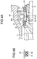
- Fig. 4A is a cross sectional view showing a principal portion (corresponding to the encircled portion in Fig. 1) of the electric power steering apparatus according to the third embodiment of the present invention.
- Fig. 4B is a partial cross sectional view showing a circumferential groove, an elastic member and a solid lubricant.
- an elastic member 51 is formed integrally with a solid lubricant 52, typified by Teflon (registered trademark), in a circumferential groove 50 formed on the outer circumferential surface of the worm shaft 3 radially inside the inner ring 20a of the second bearing 20.
- the worm shaft 3 Since friction between the worm shaft 3 and the inner ring 20a of the second bearing 20 is reduced by the solid lubricant 52, the worm shaft 3 can be shifted or tilted more smoothly. Thus, wear resistance is improved, and durability is enhanced.
- the solid lubricant 52 may be formed integrally with the elastic member 51 on one of or both the contact surfaces of the elastic member 51 and the worm shaft 3 or the inner ring 20a of the second bearing 20.
- Figs. 5A to 5C are cross sectional views of a principal portion (corresponding to the encircled portion in Fig. 1) of the electric power steering apparatus according to the fourth embodiment of the present invention, in which a projecting portion(s) is provided on the worm shaft.
- Fig. 5A shows an arrangement in which a projecting portion is provided on the worm side of the circumferential groove
- Fig. 5B shows an arrangement in which projecting portions are provided on both sides of the circumferential groove
- Fig. 5C shows an arrangement in which a projecting portion is provided on the motor side of the circumferential groove.
- a projecting portion 3b is formed at the worm 3a side (with respect to the axial direction) edge of the circumferential groove 40 of the worm shaft 3 annually along the circumferential direction with a width d.
- a small gap is formed between the outer circumference of the inner ring 20a and the inner circumferential surface of the inner ring 20a of the second bearing 20, which constitutes the circumferential surface opposed thereto, in the vicinity of the projecting portion 3b.
- the small gap formed by the projecting portion 3b allows tilting of the worm shaft 3 relative to the second bearing 20 to some extent.
- By providing the projecting portion 3b it is possible to make the gap between the worm shaft 3 and the inner ring 20a of the bearing 20 large, and therefore it is possible to enlarge the range over which the worm shaft 3 can wing.
- the worm 3a When the motor 5 generates an assist torque, the worm 3a receives a reactive force in the radial direction and is displaced in the radial direction. However, since such displacement is limited by the projecting portion 3b, the coaxiality of the worm shaft 3 and the second bearing 20 will not be deteriorated greatly. Therefore, misalignment of the worm shaft 3 and the drive shaft 6 of the motor 5 can be restricted to the minimum.
- the worm shaft 3 since when no load is applied, the worm shaft 3 is in a floating state relative to the inner ring 20a of the second bearing 20 by virtue of the elastic member 41, the worm shaft 3 will not come in contact with the inner ring 20a of the second bearing 20 when a light load caused by an input from the road surface etc. is applied on the worm 3a and a radial load is applied on the worm shaft 3. Thus, their metallic clank can be reliably prevented.
- the position of the projecting portion 3b in the fourth embodiment is not limited to this, but projecting portions may be formed on both axial sides of the circumferential groove 40 of the worm shaft 3 with each width d as shown in Fig. 5B.
- a small gap is provided between the inner circumferential surface of the inner ring 20a of the second bearing 20 and the outer circumferential surface of the worm shaft 3 by virtue of the projecting portion 3b.
- the arrangement in which the projecting portion 3b is provided on the inner ring 20a of the second bearing 20 may also be adopted.
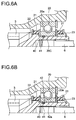
- Figs. 6A and 6B are cross sectional views showing a principal portion (corresponding to the encircled portion in Fig. 1) of the electric power steering apparatus according to the fourth embodiment, in which a projecting portion(s) is provided on the second bearing.
- Fig. 6A shows an arrangement in which the projecting portion is provided integrally with the inner ring
- Fig. 6B shows an arrangement in which the projecting portion is provided separately from the inner ring.
- a projecting portion 20c is formed on the inner circumferential surface of the inner ring 20a of the second bearing 20 (the projecting portion 20c being formed integrally with the inner ring 20a).
- the projecting portion 20c is provided at the center, with respect to the axial direction, of the inner ring 20c, and so the circumferential groove 40 of the worm shaft 3 and the O-ring 41 externally fitted therein is provided on the worm 3a side of the projecting portion 20c.
- a projecting portion 42a may be provided on a annular bush 42 as a member separate from the inner ring, and the bush 42 may be fitted inside the inner ring 20.
- the projecting portion 42a is provided at the center, with respect to the axial direction, of the inner ring as with the arrangement shown in Fig. 6A.
- the circumferential groove 40 of the worm shaft 3 and the O-ring 41 externally fitted therein are provided on the worm 3a side of the projecting portion 42a.
- a small gap is provided between the projecting portion 20c (projecting portion 42a) and the outer circumferential surface of the worm shaft 3.
Landscapes
- Engineering & Computer Science (AREA)
- General Engineering & Computer Science (AREA)
- Mechanical Engineering (AREA)
- Chemical & Material Sciences (AREA)
- Combustion & Propulsion (AREA)
- Transportation (AREA)
- Power Steering Mechanism (AREA)
- Gear Transmission (AREA)
- Support Of The Bearing (AREA)
Abstract
Description
Claims (6)
- An electric power steering apparatus that generates an assist steering torque by an electric motor in response to a steering torque applied on a steering wheel and transmits it to an output shaft of a steering mechanism while reducing it by means of a reduction gear, wherein,a drive gear shaft in said reduction gear is supported at its both ends by a first and second bearings respectively,preload means for preloading said drive gear shaft toward meshing direction with a driven gear is provided in or in the vicinity of said first bearing,a small gap is formed between said drive gear shaft and an inner ring of said second bearing to allow said drive gear shaft to be tilted relative to the inner ring of said second bearing, anda buffer member is provided in at least a portion of said small gap.
- An electric power steering apparatus according to claim 1, wherein said buffer member comprises an elastic member elastically received in a circumferential groove formed on said drive gear shaft or the inner ring of said second bearing.
- An electric power steering apparatus according to claim 2, wherein said elastic member is formed integrally with a solid lubricant in the circumferential groove formed on said drive gear shaft or the inner ring of said second shaft.
- An electric power steering apparatus according to any one of claims 1, 2 or 3, wherein said preload means preloads an outer ring of said first bearing in the meshing direction with said driven gear by an elastic member.
- An electric power steering apparatus according to any one of claims 1, 2 or 3, wherein a projecting portion is annually formed along the circumferential direction on an outer circumferential surface of said drive gear shaft or on an inner circumferential surface of the inner ring of said second bearing, on both sides or one side, with respect to the axial direction, of said circumferential groove in such a way as to leave a small gap between the outer circumferential surface of the drive gear shaft and the inner circumferential surface of the inner ring of the second bearing.
- An electric power steering apparatus according to claim 4, wherein a projecting portion is annually formed along the circumferential direction on an outer circumferential surface of said drive gear shaft or on an inner circumferential surface of the inner ring of said second bearing, on both sides or one side, with respect to the axial direction, of said circumferential groove in such a way as to leave a small gap between the outer circumferential surface of the drive gear shaft and the inner circumferential surface of the inner ring of the second bearing.
Applications Claiming Priority (3)
| Application Number | Priority Date | Filing Date | Title |
|---|---|---|---|
| JP2002357165 | 2002-12-09 | ||
| JP2002357165 | 2002-12-09 | ||
| PCT/JP2003/015710 WO2004052712A1 (en) | 2002-12-09 | 2003-12-09 | Electric power steering device |
Publications (3)
| Publication Number | Publication Date |
|---|---|
| EP1571067A1 true EP1571067A1 (en) | 2005-09-07 |
| EP1571067A4 EP1571067A4 (en) | 2007-12-12 |
| EP1571067B1 EP1571067B1 (en) | 2018-01-24 |
Family
ID=32500842
Family Applications (1)
| Application Number | Title | Priority Date | Filing Date |
|---|---|---|---|
| EP03777381.9A Expired - Lifetime EP1571067B1 (en) | 2002-12-09 | 2003-12-09 | Electric power steering device |
Country Status (7)
| Country | Link |
|---|---|
| US (1) | US7490695B2 (en) |
| EP (1) | EP1571067B1 (en) |
| JP (1) | JP4442421B2 (en) |
| KR (1) | KR20050084203A (en) |
| CN (1) | CN100411934C (en) |
| AU (1) | AU2003289261A1 (en) |
| WO (1) | WO2004052712A1 (en) |
Cited By (17)
| Publication number | Priority date | Publication date | Assignee | Title |
|---|---|---|---|---|
| EP1764285A1 (en) * | 2005-09-20 | 2007-03-21 | Mando Corporation | Electric power steering apparatus for automobile |
| WO2008017541A1 (en) * | 2006-08-10 | 2008-02-14 | Zf Lenksysteme Gmbh | Servo steering |
| DE102008042609A1 (en) * | 2008-10-06 | 2010-04-08 | Zf Lenksysteme Gmbh | Bearing device for worm in steering gear of power steering, has inner ring for accommodating shaft end of worm to mount shaft end in housing, and spring for subjecting inner ring with axially acting force |
| WO2011065491A1 (en) | 2009-11-27 | 2011-06-03 | 日本精工株式会社 | Motorized power steering device |
| EP2450262A1 (en) * | 2010-11-09 | 2012-05-09 | JTEKT Corporation | Electric power steering system |
| EP2465752A1 (en) | 2010-12-16 | 2012-06-20 | ThyssenKrupp Presta AG | Power steering with spherical bearing |
| EP2466160A2 (en) | 2010-12-16 | 2012-06-20 | ThyssenKrupp Presta AG | Dampening element for a spindle drive with elastic bearing |
| WO2012079726A1 (en) | 2010-12-16 | 2012-06-21 | Thyssenkrupp Presta Ag | Power steering system with spindle drive |
| DE102011116058A1 (en) | 2011-10-18 | 2013-04-18 | Thyssenkrupp Presta Ag | Electromechanical vehicle steering |
| EP2423075A3 (en) * | 2010-08-30 | 2013-12-04 | Jtekt Corporation | Electric power steering system |
| EP2547572A4 (en) * | 2010-03-15 | 2014-03-19 | Trw Automotive Us Llc | Electric power steering assembly |
| WO2014135382A1 (en) * | 2013-03-06 | 2014-09-12 | Thyssenkrupp Presta Ag | Angularly movable bearing arrangement for pinions in reduction gears of electromechanical steering systems |
| DE102013006432A1 (en) | 2013-04-15 | 2014-10-16 | Thyssenkrupp Presta Aktiengesellschaft | Double wave spring with damping intermediate layer |
| EP2829458A1 (en) * | 2013-07-25 | 2015-01-28 | Jtekt Corporation | Electric power steering system |
| KR20160002512A (en) * | 2014-06-30 | 2016-01-08 | 현대모비스 주식회사 | Motor driven power steering system |
| EP2842835A4 (en) * | 2012-04-25 | 2016-04-06 | Jtekt Corp | Electric power steering device |
| US11035454B2 (en) | 2018-10-05 | 2021-06-15 | Fanuc Corporation | Rotational-force transmitting part |
Families Citing this family (45)
| Publication number | Priority date | Publication date | Assignee | Title |
|---|---|---|---|---|
| JP2007112305A (en) * | 2005-10-20 | 2007-05-10 | Nsk Ltd | Electric power steering device |
| KR100723732B1 (en) * | 2005-11-02 | 2007-05-30 | 주식회사 만도 | Electric power assist steering with worm gear clearance compensation |
| KR100897787B1 (en) * | 2006-11-01 | 2009-05-15 | 남양공업주식회사 | Worm shaft play compensator of electric power steering system |
| WO2008093861A1 (en) * | 2007-01-30 | 2008-08-07 | Nsk Ltd. | Electric power steering device |
| DE102007055814A1 (en) * | 2007-12-14 | 2009-06-18 | Zf Lenksysteme Gmbh | Radially movable bearing |
| JP5176549B2 (en) * | 2008-01-08 | 2013-04-03 | 日本精工株式会社 | Electric power steering device |
| US8327971B2 (en) * | 2009-09-24 | 2012-12-11 | Mando Corporation | Reducer of electric power steering apparatus |
| JP2012001050A (en) * | 2010-06-15 | 2012-01-05 | Jtekt Corp | Electric power steering device |
| JP2012102799A (en) * | 2010-11-10 | 2012-05-31 | Honda Motor Co Ltd | Worm reduction gear |
| FR2972514B1 (en) * | 2011-03-09 | 2013-09-06 | Skf Ab | WEAR COMPENSATION DEVICE FOR GEAR. |
| GB2489021B (en) * | 2011-03-16 | 2013-08-14 | Flybrid Automotive Ltd | High speed flywheel |
| KR101304872B1 (en) * | 2011-07-04 | 2013-09-06 | 남양공업주식회사 | Wormshaft damping structure of motor driven power steering system |
| CN103057581A (en) * | 2011-10-24 | 2013-04-24 | 蒂森克虏伯普利斯坦有限公司 | Electromechanical motor vehicle steering device |
| JP2013103696A (en) * | 2011-11-16 | 2013-05-30 | Jtekt Corp | Electric power steering system |
| JP6020893B2 (en) | 2012-07-27 | 2016-11-02 | 株式会社ジェイテクト | Electric power steering device |
| DE102013207142B4 (en) * | 2013-04-19 | 2014-12-11 | Ford Global Technologies, Llc | worm gear |
| JP2013152026A (en) * | 2013-04-26 | 2013-08-08 | Nsk Ltd | Rotation transmission mechanism and lubricating grease used for the same |
| KR101477906B1 (en) * | 2013-05-28 | 2014-12-30 | 주식회사 만도 | Reducer of Electric Power Steering Apparatus |
| KR101477907B1 (en) * | 2013-05-29 | 2014-12-30 | 주식회사 만도 | Reducer of Electric Power Steering Apparatus |
| KR102281681B1 (en) | 2015-01-12 | 2021-07-27 | 주식회사 만도 | Reducer for vehicle |
| KR102281674B1 (en) * | 2015-01-12 | 2021-07-27 | 주식회사 만도 | Reducer for vehicle |
| GB201504958D0 (en) | 2015-03-24 | 2015-05-06 | Trw Ltd | A gearbox assembly for an electric power steering assembly |
| GB201506710D0 (en) * | 2015-04-21 | 2015-06-03 | Cambridge Medical Robotics Ltd | Load cells in an instrument drive |
| US9744987B2 (en) * | 2015-04-29 | 2017-08-29 | Steering Solutions Ip Holding Corporation | Worm shaft subassembly |
| US10308277B2 (en) * | 2015-07-22 | 2019-06-04 | Steering Solutions Ip Holding Corporation | Spherical washer assembly |
| DE102016211695A1 (en) | 2016-06-29 | 2018-01-04 | Ford Global Technologies, Llc | Transmission unit for a motor vehicle |
| DE202016103794U1 (en) | 2016-06-29 | 2016-07-29 | Ford Global Technologies, Llc | Transmission unit for a motor vehicle |
| DE102016211694B3 (en) * | 2016-06-29 | 2017-10-05 | Ford Global Technologies, Llc | Transmission unit for a motor vehicle |
| DE102016211707A1 (en) | 2016-06-29 | 2018-01-04 | Ford Global Technologies, Llc | Transmission unit for a motor vehicle |
| DE102016211706B3 (en) * | 2016-06-29 | 2017-12-14 | Ford Global Technologies, Llc | Transmission unit for a motor vehicle |
| DE202016103799U1 (en) | 2016-06-29 | 2016-07-27 | Ford Global Technologies, Llc | Transmission unit for a motor vehicle |
| DE102016211714B3 (en) * | 2016-06-29 | 2017-09-07 | Ford Global Technologies, Llc | Transmission unit for a motor vehicle |
| KR102635281B1 (en) * | 2017-02-01 | 2024-02-13 | 에이치엘만도 주식회사 | Reducer of Electric Power Steering Apparatus |
| DE102017210876A1 (en) * | 2017-06-28 | 2019-01-03 | Robert Bosch Gmbh | Carrier device, arrangement with a carrier device and method for forming an arrangement with a carrier device |
| GB201710388D0 (en) | 2017-06-29 | 2017-08-16 | Trw Ltd | Gearbox assembly |
| DE102017115573A1 (en) | 2017-07-12 | 2019-01-17 | Schaeffler Technologies AG & Co. KG | Rolling bearing with tolerance ring for a power steering system |
| KR102488782B1 (en) * | 2017-08-21 | 2023-01-16 | 엘지이노텍 주식회사 | Gearbox and actuator having the same |
| JP6910904B2 (en) * | 2017-09-25 | 2021-07-28 | 住友重機械工業株式会社 | Flexible meshing gear device |
| KR101993295B1 (en) * | 2017-12-19 | 2019-06-26 | 주식회사 만도 | Reducer of Electric Power Steering Apparatus |
| KR102033558B1 (en) * | 2018-05-18 | 2019-10-17 | 주식회사 만도 | Reducer of Electric power steering apparatus |
| BE1028066B9 (en) * | 2020-02-18 | 2021-10-18 | Punch Powertrain | Shaft composition, retaining element and methods |
| CN112944010A (en) * | 2021-04-02 | 2021-06-11 | 上海孚因流体动力设备股份有限公司 | Electric actuator with high-stability transmission mechanism |
| KR20220159218A (en) * | 2021-05-25 | 2022-12-02 | 에이치엘만도 주식회사 | Driving part of power steering apparatus |
| JP7751442B2 (en) * | 2021-10-13 | 2025-10-08 | Nskステアリング&コントロール株式会社 | Electric assist device and worm damper for electric assist device |
| CN121713003A (en) | 2023-08-24 | 2026-03-20 | 恩斯克转向及控制公司 | Worm speed reducer |
Family Cites Families (18)
| Publication number | Priority date | Publication date | Assignee | Title |
|---|---|---|---|---|
| JP3799236B2 (en) * | 2001-01-22 | 2006-07-19 | 株式会社ジェイテクト | Electric power steering device |
| DE3930970A1 (en) * | 1989-09-16 | 1991-03-28 | Schaeffler Waelzlager Kg | TOLERANCE RING MADE OF POLYMER MATERIAL |
| DE4139984A1 (en) * | 1991-12-04 | 1993-06-09 | Robert Bosch Gmbh, 7000 Stuttgart, De | DC motor for motor vehicle antilocking or drive slip regulated braking - has resilient element providing cushioning between motor shaft bearing pin and bearing seat to reduce noise |
| JPH08207792A (en) * | 1995-01-31 | 1996-08-13 | Koyo Seiko Co Ltd | Power steering system |
| GB2327652B (en) * | 1997-05-29 | 2001-04-18 | Nsk Ltd | Electric power assisted steering apparatus |
| JP3376869B2 (en) * | 1997-05-29 | 2003-02-10 | 日本精工株式会社 | Electric power steering device |
| GB9718574D0 (en) | 1997-09-03 | 1997-11-05 | Lucas Ind Plc | Improvements relating to gears |
| DE19747638C1 (en) * | 1997-10-29 | 1999-07-01 | Zahnradfabrik Friedrichshafen | Electrically assisted power steering for motor vehicles |
| JP3716616B2 (en) | 1998-04-24 | 2005-11-16 | 日本精工株式会社 | Worm reducer and linear actuator with worm reducer |
| GB9812844D0 (en) | 1998-06-16 | 1998-08-12 | Lucas Ind Plc | Improvements relating to electrical power assisted steering |
| JP3430954B2 (en) * | 1999-01-25 | 2003-07-28 | トヨタ自動車株式会社 | Electric power steering device |
| JP3653611B2 (en) * | 2000-05-18 | 2005-06-02 | 光洋精工株式会社 | Electric steering device |
| JP2002021943A (en) * | 2000-07-04 | 2002-01-23 | Koyo Seiko Co Ltd | Motor-driven steering device |
| JP4654532B2 (en) * | 2001-04-25 | 2011-03-23 | 株式会社ジェイテクト | Joint structure, reduction mechanism and steering assist device using the same |
| US7077235B2 (en) * | 2001-12-03 | 2006-07-18 | Nsk Ltd. | Electric power steering device |
| JP3765276B2 (en) * | 2002-03-06 | 2006-04-12 | 株式会社ジェイテクト | Electric power steering device |
| DE60310782T2 (en) * | 2002-02-04 | 2007-10-11 | Jtekt Corp., Osaka | Electric power steering |
| JP4016755B2 (en) | 2002-07-30 | 2007-12-05 | 株式会社ジェイテクト | Electric power steering device |
-
2003
- 2003-12-09 CN CNB2003801054901A patent/CN100411934C/en not_active Expired - Lifetime
- 2003-12-09 JP JP2004558443A patent/JP4442421B2/en not_active Expired - Lifetime
- 2003-12-09 AU AU2003289261A patent/AU2003289261A1/en not_active Abandoned
- 2003-12-09 WO PCT/JP2003/015710 patent/WO2004052712A1/en not_active Ceased
- 2003-12-09 KR KR1020057010361A patent/KR20050084203A/en not_active Withdrawn
- 2003-12-09 EP EP03777381.9A patent/EP1571067B1/en not_active Expired - Lifetime
-
2005
- 2005-06-08 US US11/147,364 patent/US7490695B2/en not_active Expired - Lifetime
Cited By (33)
| Publication number | Priority date | Publication date | Assignee | Title |
|---|---|---|---|---|
| EP1764285A1 (en) * | 2005-09-20 | 2007-03-21 | Mando Corporation | Electric power steering apparatus for automobile |
| CN100457527C (en) * | 2005-09-20 | 2009-02-04 | 株式会社万都 | Electric power steering apparatus for automobile |
| US7493986B2 (en) | 2005-09-20 | 2009-02-24 | Mando Corporation | Electric power steering apparatus for automobile |
| WO2008017541A1 (en) * | 2006-08-10 | 2008-02-14 | Zf Lenksysteme Gmbh | Servo steering |
| DE102008042609A1 (en) * | 2008-10-06 | 2010-04-08 | Zf Lenksysteme Gmbh | Bearing device for worm in steering gear of power steering, has inner ring for accommodating shaft end of worm to mount shaft end in housing, and spring for subjecting inner ring with axially acting force |
| CN102224058A (en) * | 2009-11-27 | 2011-10-19 | 日本精工株式会社 | Electric power steering device |
| EP2351681A4 (en) * | 2009-11-27 | 2013-05-29 | Nsk Ltd | ELECTRIC DIRECTION DEVICE |
| WO2011065491A1 (en) | 2009-11-27 | 2011-06-03 | 日本精工株式会社 | Motorized power steering device |
| CN102224058B (en) * | 2009-11-27 | 2015-08-19 | 日本精工株式会社 | Electric Power Steering |
| EP2547572A4 (en) * | 2010-03-15 | 2014-03-19 | Trw Automotive Us Llc | Electric power steering assembly |
| EP2423075A3 (en) * | 2010-08-30 | 2013-12-04 | Jtekt Corporation | Electric power steering system |
| EP2450262A1 (en) * | 2010-11-09 | 2012-05-09 | JTEKT Corporation | Electric power steering system |
| US8459402B2 (en) | 2010-11-09 | 2013-06-11 | Jtekt Corporation | Electric power steering system |
| EP2465752A1 (en) | 2010-12-16 | 2012-06-20 | ThyssenKrupp Presta AG | Power steering with spherical bearing |
| DE102010054828A1 (en) | 2010-12-16 | 2012-06-21 | Thyssenkrupp Presta Ag | Power steering with spindle drive |
| WO2012079726A1 (en) | 2010-12-16 | 2012-06-21 | Thyssenkrupp Presta Ag | Power steering system with spindle drive |
| DE102010054830A1 (en) | 2010-12-16 | 2012-06-21 | Thyssenkrupp Presta Ag | Power steering with spherical bearing |
| DE102010054833A1 (en) | 2010-12-16 | 2012-06-21 | Thyssenkrupp Presta Ag | Damping element for an elastically mounted spindle drive |
| EP2466160A2 (en) | 2010-12-16 | 2012-06-20 | ThyssenKrupp Presta AG | Dampening element for a spindle drive with elastic bearing |
| WO2013056770A1 (en) | 2011-10-18 | 2013-04-25 | Thyssenkrupp Presta Ag | Electromechanical motor vehicle steering system |
| DE102011116058A1 (en) | 2011-10-18 | 2013-04-18 | Thyssenkrupp Presta Ag | Electromechanical vehicle steering |
| US9033097B2 (en) | 2011-10-18 | 2015-05-19 | Thyssenkrupp Presta Ag | Electromechanical motor vehicle steering system |
| EP2842835A4 (en) * | 2012-04-25 | 2016-04-06 | Jtekt Corp | Electric power steering device |
| US9638307B2 (en) | 2012-04-25 | 2017-05-02 | Jtekt Corporation | Electric power steering device |
| WO2014135382A1 (en) * | 2013-03-06 | 2014-09-12 | Thyssenkrupp Presta Ag | Angularly movable bearing arrangement for pinions in reduction gears of electromechanical steering systems |
| US9988071B2 (en) | 2013-03-06 | 2018-06-05 | Thyssenkrupp Presta Ag | Angularly movable bearing arrangement for pinions in reduction gears of electromechanical steering systems |
| WO2014170125A1 (en) | 2013-04-15 | 2014-10-23 | Thyssenkrupp Presta Ag | Double wave spring with insulating intermediate layer |
| US9409594B2 (en) | 2013-04-15 | 2016-08-09 | Thyssenkrupp Presta Ag | Power steering system incorporating double wave spring with insulating intermediate layer |
| DE102013006432A1 (en) | 2013-04-15 | 2014-10-16 | Thyssenkrupp Presta Aktiengesellschaft | Double wave spring with damping intermediate layer |
| US9499194B2 (en) | 2013-07-25 | 2016-11-22 | Jtekt Corporation | Electric power steering system |
| EP2829458A1 (en) * | 2013-07-25 | 2015-01-28 | Jtekt Corporation | Electric power steering system |
| KR20160002512A (en) * | 2014-06-30 | 2016-01-08 | 현대모비스 주식회사 | Motor driven power steering system |
| US11035454B2 (en) | 2018-10-05 | 2021-06-15 | Fanuc Corporation | Rotational-force transmitting part |
Also Published As
| Publication number | Publication date |
|---|---|
| CN100411934C (en) | 2008-08-20 |
| JP4442421B2 (en) | 2010-03-31 |
| US7490695B2 (en) | 2009-02-17 |
| KR20050084203A (en) | 2005-08-26 |
| AU2003289261A1 (en) | 2004-06-30 |
| US20050224278A1 (en) | 2005-10-13 |
| EP1571067A4 (en) | 2007-12-12 |
| WO2004052712A1 (en) | 2004-06-24 |
| JPWO2004052712A1 (en) | 2006-04-06 |
| CN1723146A (en) | 2006-01-18 |
| EP1571067B1 (en) | 2018-01-24 |
Similar Documents
| Publication | Publication Date | Title |
|---|---|---|
| US7490695B2 (en) | Electric power steering apparatus | |
| EP1335154B1 (en) | Electric power steering apparatus | |
| CN102216144B (en) | Mechanisms that convert rotary motion into linear motion with isolators | |
| EP2371675B1 (en) | Electric power steering device | |
| EP1970598B1 (en) | Feed screw mechanism | |
| KR102033558B1 (en) | Reducer of Electric power steering apparatus | |
| US20180058556A1 (en) | A Gearbox Assembly for an Electric Power Steering Assembly | |
| KR20210112540A (en) | Steering apparatus for vehicle | |
| JP4755363B2 (en) | Backlash adjustment device for worm speed reducer | |
| JP2005219708A (en) | Electric power steering device | |
| KR20070057250A (en) | Electric power steering | |
| US20200369314A1 (en) | Power steering device | |
| KR102898949B1 (en) | Steer-by-wire type steering apparatus | |
| JP2004189039A (en) | Electric power steering device | |
| CN112013091A (en) | Ball nut assembly support for vehicle power steering assembly | |
| US11827288B2 (en) | Gearbox assembly for an electric power steering apparatus | |
| WO2020145244A1 (en) | Rolling bearing | |
| JP4085802B2 (en) | Electric power steering device | |
| JP4574228B2 (en) | Ball screw for electric actuator | |
| JP2005212559A (en) | Electric power steering device | |
| JP7222263B2 (en) | electric power steering device | |
| JP7751442B2 (en) | Electric assist device and worm damper for electric assist device | |
| KR102944318B1 (en) | Gap compensation mechanism for electric power steering | |
| JP2007232023A (en) | Motor-driven actuator | |
| JP4450721B2 (en) | Shock absorption structure of propeller shaft |
Legal Events
| Date | Code | Title | Description |
|---|---|---|---|
| PUAI | Public reference made under article 153(3) epc to a published international application that has entered the european phase |
Free format text: ORIGINAL CODE: 0009012 |
|
| 17P | Request for examination filed |
Effective date: 20050704 |
|
| AK | Designated contracting states |
Kind code of ref document: A1 Designated state(s): AT BE BG CH CY CZ DE DK EE ES FI FR GB GR HU IE IT LI LU MC NL PT RO SE SI SK TR |
|
| AX | Request for extension of the european patent |
Extension state: AL LT LV MK |
|
| DAX | Request for extension of the european patent (deleted) | ||
| A4 | Supplementary search report drawn up and despatched |
Effective date: 20071108 |
|
| 17Q | First examination report despatched |
Effective date: 20080313 |
|
| REG | Reference to a national code |
Ref country code: DE Ref legal event code: R079 Ref document number: 60350944 Country of ref document: DE Free format text: PREVIOUS MAIN CLASS: B62D0005040000 Ipc: F16C0019540000 |
|
| RIC1 | Information provided on ipc code assigned before grant |
Ipc: F16H 57/021 20120101ALI20170502BHEP Ipc: F16C 35/07 20060101ALI20170502BHEP Ipc: F16C 19/06 20060101ALI20170502BHEP Ipc: F16C 19/54 20060101AFI20170502BHEP Ipc: B62D 5/04 20060101ALI20170502BHEP Ipc: F16H 55/24 20060101ALI20170502BHEP Ipc: F16C 35/063 20060101ALI20170502BHEP Ipc: F16H 57/00 20120101ALI20170502BHEP Ipc: F16C 27/06 20060101ALI20170502BHEP Ipc: F16H 1/16 20060101ALI20170502BHEP |
|
| GRAP | Despatch of communication of intention to grant a patent |
Free format text: ORIGINAL CODE: EPIDOSNIGR1 |
|
| STAA | Information on the status of an ep patent application or granted ep patent |
Free format text: STATUS: GRANT OF PATENT IS INTENDED |
|
| INTG | Intention to grant announced |
Effective date: 20170704 |
|
| GRAS | Grant fee paid |
Free format text: ORIGINAL CODE: EPIDOSNIGR3 |
|
| GRAA | (expected) grant |
Free format text: ORIGINAL CODE: 0009210 |
|
| STAA | Information on the status of an ep patent application or granted ep patent |
Free format text: STATUS: THE PATENT HAS BEEN GRANTED |
|
| AK | Designated contracting states |
Kind code of ref document: B1 Designated state(s): AT BE BG CH CY CZ DE DK EE ES FI FR GB GR HU IE IT LI LU MC NL PT RO SE SI SK TR |
|
| REG | Reference to a national code |
Ref country code: GB Ref legal event code: FG4D |
|
| REG | Reference to a national code |
Ref country code: CH Ref legal event code: EP |
|
| REG | Reference to a national code |
Ref country code: AT Ref legal event code: REF Ref document number: 965951 Country of ref document: AT Kind code of ref document: T Effective date: 20180215 |
|
| REG | Reference to a national code |
Ref country code: IE Ref legal event code: FG4D |
|
| REG | Reference to a national code |
Ref country code: DE Ref legal event code: R096 Ref document number: 60350944 Country of ref document: DE |
|
| REG | Reference to a national code |
Ref country code: NL Ref legal event code: MP Effective date: 20180124 |
|
| REG | Reference to a national code |
Ref country code: AT Ref legal event code: MK05 Ref document number: 965951 Country of ref document: AT Kind code of ref document: T Effective date: 20180124 |
|
| PG25 | Lapsed in a contracting state [announced via postgrant information from national office to epo] |
Ref country code: NL Free format text: LAPSE BECAUSE OF FAILURE TO SUBMIT A TRANSLATION OF THE DESCRIPTION OR TO PAY THE FEE WITHIN THE PRESCRIBED TIME-LIMIT Effective date: 20180124 |
|
| PG25 | Lapsed in a contracting state [announced via postgrant information from national office to epo] |
Ref country code: ES Free format text: LAPSE BECAUSE OF FAILURE TO SUBMIT A TRANSLATION OF THE DESCRIPTION OR TO PAY THE FEE WITHIN THE PRESCRIBED TIME-LIMIT Effective date: 20180124 Ref country code: CY Free format text: LAPSE BECAUSE OF FAILURE TO SUBMIT A TRANSLATION OF THE DESCRIPTION OR TO PAY THE FEE WITHIN THE PRESCRIBED TIME-LIMIT Effective date: 20180124 Ref country code: FI Free format text: LAPSE BECAUSE OF FAILURE TO SUBMIT A TRANSLATION OF THE DESCRIPTION OR TO PAY THE FEE WITHIN THE PRESCRIBED TIME-LIMIT Effective date: 20180124 |
|
| PG25 | Lapsed in a contracting state [announced via postgrant information from national office to epo] |
Ref country code: GR Free format text: LAPSE BECAUSE OF FAILURE TO SUBMIT A TRANSLATION OF THE DESCRIPTION OR TO PAY THE FEE WITHIN THE PRESCRIBED TIME-LIMIT Effective date: 20180425 Ref country code: SE Free format text: LAPSE BECAUSE OF FAILURE TO SUBMIT A TRANSLATION OF THE DESCRIPTION OR TO PAY THE FEE WITHIN THE PRESCRIBED TIME-LIMIT Effective date: 20180124 Ref country code: BG Free format text: LAPSE BECAUSE OF FAILURE TO SUBMIT A TRANSLATION OF THE DESCRIPTION OR TO PAY THE FEE WITHIN THE PRESCRIBED TIME-LIMIT Effective date: 20180424 Ref country code: AT Free format text: LAPSE BECAUSE OF FAILURE TO SUBMIT A TRANSLATION OF THE DESCRIPTION OR TO PAY THE FEE WITHIN THE PRESCRIBED TIME-LIMIT Effective date: 20180124 |
|
| REG | Reference to a national code |
Ref country code: DE Ref legal event code: R097 Ref document number: 60350944 Country of ref document: DE |
|
| PG25 | Lapsed in a contracting state [announced via postgrant information from national office to epo] |
Ref country code: IT Free format text: LAPSE BECAUSE OF FAILURE TO SUBMIT A TRANSLATION OF THE DESCRIPTION OR TO PAY THE FEE WITHIN THE PRESCRIBED TIME-LIMIT Effective date: 20180124 Ref country code: EE Free format text: LAPSE BECAUSE OF FAILURE TO SUBMIT A TRANSLATION OF THE DESCRIPTION OR TO PAY THE FEE WITHIN THE PRESCRIBED TIME-LIMIT Effective date: 20180124 Ref country code: RO Free format text: LAPSE BECAUSE OF FAILURE TO SUBMIT A TRANSLATION OF THE DESCRIPTION OR TO PAY THE FEE WITHIN THE PRESCRIBED TIME-LIMIT Effective date: 20180124 |
|
| PG25 | Lapsed in a contracting state [announced via postgrant information from national office to epo] |
Ref country code: DK Free format text: LAPSE BECAUSE OF FAILURE TO SUBMIT A TRANSLATION OF THE DESCRIPTION OR TO PAY THE FEE WITHIN THE PRESCRIBED TIME-LIMIT Effective date: 20180124 Ref country code: CZ Free format text: LAPSE BECAUSE OF FAILURE TO SUBMIT A TRANSLATION OF THE DESCRIPTION OR TO PAY THE FEE WITHIN THE PRESCRIBED TIME-LIMIT Effective date: 20180124 Ref country code: SK Free format text: LAPSE BECAUSE OF FAILURE TO SUBMIT A TRANSLATION OF THE DESCRIPTION OR TO PAY THE FEE WITHIN THE PRESCRIBED TIME-LIMIT Effective date: 20180124 |
|
| PLBE | No opposition filed within time limit |
Free format text: ORIGINAL CODE: 0009261 |
|
| STAA | Information on the status of an ep patent application or granted ep patent |
Free format text: STATUS: NO OPPOSITION FILED WITHIN TIME LIMIT |
|
| 26N | No opposition filed |
Effective date: 20181025 |
|
| PG25 | Lapsed in a contracting state [announced via postgrant information from national office to epo] |
Ref country code: SI Free format text: LAPSE BECAUSE OF FAILURE TO SUBMIT A TRANSLATION OF THE DESCRIPTION OR TO PAY THE FEE WITHIN THE PRESCRIBED TIME-LIMIT Effective date: 20180124 |
|
| REG | Reference to a national code |
Ref country code: CH Ref legal event code: PL |
|
| PG25 | Lapsed in a contracting state [announced via postgrant information from national office to epo] |
Ref country code: LU Free format text: LAPSE BECAUSE OF NON-PAYMENT OF DUE FEES Effective date: 20181209 Ref country code: MC Free format text: LAPSE BECAUSE OF FAILURE TO SUBMIT A TRANSLATION OF THE DESCRIPTION OR TO PAY THE FEE WITHIN THE PRESCRIBED TIME-LIMIT Effective date: 20180124 |
|
| REG | Reference to a national code |
Ref country code: IE Ref legal event code: MM4A |
|
| REG | Reference to a national code |
Ref country code: BE Ref legal event code: MM Effective date: 20181231 |
|
| PG25 | Lapsed in a contracting state [announced via postgrant information from national office to epo] |
Ref country code: IE Free format text: LAPSE BECAUSE OF NON-PAYMENT OF DUE FEES Effective date: 20181209 |
|
| PG25 | Lapsed in a contracting state [announced via postgrant information from national office to epo] |
Ref country code: BE Free format text: LAPSE BECAUSE OF NON-PAYMENT OF DUE FEES Effective date: 20181231 |
|
| PG25 | Lapsed in a contracting state [announced via postgrant information from national office to epo] |
Ref country code: LI Free format text: LAPSE BECAUSE OF NON-PAYMENT OF DUE FEES Effective date: 20181231 Ref country code: CH Free format text: LAPSE BECAUSE OF NON-PAYMENT OF DUE FEES Effective date: 20181231 |
|
| PG25 | Lapsed in a contracting state [announced via postgrant information from national office to epo] |
Ref country code: TR Free format text: LAPSE BECAUSE OF FAILURE TO SUBMIT A TRANSLATION OF THE DESCRIPTION OR TO PAY THE FEE WITHIN THE PRESCRIBED TIME-LIMIT Effective date: 20180124 |
|
| PG25 | Lapsed in a contracting state [announced via postgrant information from national office to epo] |
Ref country code: PT Free format text: LAPSE BECAUSE OF FAILURE TO SUBMIT A TRANSLATION OF THE DESCRIPTION OR TO PAY THE FEE WITHIN THE PRESCRIBED TIME-LIMIT Effective date: 20180124 |
|
| PG25 | Lapsed in a contracting state [announced via postgrant information from national office to epo] |
Ref country code: HU Free format text: LAPSE BECAUSE OF FAILURE TO SUBMIT A TRANSLATION OF THE DESCRIPTION OR TO PAY THE FEE WITHIN THE PRESCRIBED TIME-LIMIT; INVALID AB INITIO Effective date: 20031209 |
|
| PGFP | Annual fee paid to national office [announced via postgrant information from national office to epo] |
Ref country code: GB Payment date: 20201203 Year of fee payment: 18 Ref country code: FR Payment date: 20201112 Year of fee payment: 18 |
|
| GBPC | Gb: european patent ceased through non-payment of renewal fee |
Effective date: 20211209 |
|
| PG25 | Lapsed in a contracting state [announced via postgrant information from national office to epo] |
Ref country code: GB Free format text: LAPSE BECAUSE OF NON-PAYMENT OF DUE FEES Effective date: 20211209 |
|
| PG25 | Lapsed in a contracting state [announced via postgrant information from national office to epo] |
Ref country code: FR Free format text: LAPSE BECAUSE OF NON-PAYMENT OF DUE FEES Effective date: 20211231 |
|
| PGFP | Annual fee paid to national office [announced via postgrant information from national office to epo] |
Ref country code: DE Payment date: 20221102 Year of fee payment: 20 |
|
| REG | Reference to a national code |
Ref country code: DE Ref legal event code: R071 Ref document number: 60350944 Country of ref document: DE |