EP2450262A1 - Electric power steering system - Google Patents
Electric power steering system Download PDFInfo
- Publication number
- EP2450262A1 EP2450262A1 EP11187772A EP11187772A EP2450262A1 EP 2450262 A1 EP2450262 A1 EP 2450262A1 EP 11187772 A EP11187772 A EP 11187772A EP 11187772 A EP11187772 A EP 11187772A EP 2450262 A1 EP2450262 A1 EP 2450262A1
- Authority
- EP
- European Patent Office
- Prior art keywords
- bearing
- worm shaft
- worm
- raceway groove
- shaft
- Prior art date
- Legal status (The legal status is an assumption and is not a legal conclusion. Google has not performed a legal analysis and makes no representation as to the accuracy of the status listed.)
- Granted
Links
- 238000005096 rolling process Methods 0.000 claims abstract description 48
- 238000003825 pressing Methods 0.000 claims abstract description 41
- 230000002093 peripheral effect Effects 0.000 claims description 15
- 230000007246 mechanism Effects 0.000 claims description 12
- 230000007423 decrease Effects 0.000 claims description 5
- 230000014759 maintenance of location Effects 0.000 claims description 2
- 230000008878 coupling Effects 0.000 description 33
- 238000010168 coupling process Methods 0.000 description 33
- 238000005859 coupling reaction Methods 0.000 description 33
- 230000009467 reduction Effects 0.000 description 12
- 229920003002 synthetic resin Polymers 0.000 description 5
- 239000000057 synthetic resin Substances 0.000 description 5
- 238000006243 chemical reaction Methods 0.000 description 4
- 230000006835 compression Effects 0.000 description 3
- 238000007906 compression Methods 0.000 description 3
- XEEYBQQBJWHFJM-UHFFFAOYSA-N Iron Chemical compound [Fe] XEEYBQQBJWHFJM-UHFFFAOYSA-N 0.000 description 2
- 239000000853 adhesive Substances 0.000 description 2
- 230000001070 adhesive effect Effects 0.000 description 2
- 238000005520 cutting process Methods 0.000 description 2
- 229910052751 metal Inorganic materials 0.000 description 2
- 239000002184 metal Substances 0.000 description 2
- 230000010355 oscillation Effects 0.000 description 2
- 229910000838 Al alloy Inorganic materials 0.000 description 1
- 229910000831 Steel Inorganic materials 0.000 description 1
- 230000008859 change Effects 0.000 description 1
- 238000006073 displacement reaction Methods 0.000 description 1
- 239000013013 elastic material Substances 0.000 description 1
- 229920001971 elastomer Polymers 0.000 description 1
- 229910052742 iron Inorganic materials 0.000 description 1
- 238000004519 manufacturing process Methods 0.000 description 1
- 239000000463 material Substances 0.000 description 1
- 239000007769 metal material Substances 0.000 description 1
- 238000000465 moulding Methods 0.000 description 1
- 229920005989 resin Polymers 0.000 description 1
- 239000011347 resin Substances 0.000 description 1
- 239000005060 rubber Substances 0.000 description 1
- 239000010959 steel Substances 0.000 description 1
- 229920003051 synthetic elastomer Polymers 0.000 description 1
- 239000005061 synthetic rubber Substances 0.000 description 1
Images


Classifications
-
- B—PERFORMING OPERATIONS; TRANSPORTING
- B62—LAND VEHICLES FOR TRAVELLING OTHERWISE THAN ON RAILS
- B62D—MOTOR VEHICLES; TRAILERS
- B62D5/00—Power-assisted or power-driven steering
- B62D5/04—Power-assisted or power-driven steering electrical, e.g. using an electric servo-motor connected to, or forming part of, the steering gear
- B62D5/0409—Electric motor acting on the steering column
-
- F—MECHANICAL ENGINEERING; LIGHTING; HEATING; WEAPONS; BLASTING
- F16—ENGINEERING ELEMENTS AND UNITS; GENERAL MEASURES FOR PRODUCING AND MAINTAINING EFFECTIVE FUNCTIONING OF MACHINES OR INSTALLATIONS; THERMAL INSULATION IN GENERAL
- F16C—SHAFTS; FLEXIBLE SHAFTS; ELEMENTS OR CRANKSHAFT MECHANISMS; ROTARY BODIES OTHER THAN GEARING ELEMENTS; BEARINGS
- F16C27/00—Elastic or yielding bearings or bearing supports, for exclusively rotary movement
- F16C27/06—Elastic or yielding bearings or bearing supports, for exclusively rotary movement by means of parts of rubber or like materials
- F16C27/066—Ball or roller bearings
-
- F—MECHANICAL ENGINEERING; LIGHTING; HEATING; WEAPONS; BLASTING
- F16—ENGINEERING ELEMENTS AND UNITS; GENERAL MEASURES FOR PRODUCING AND MAINTAINING EFFECTIVE FUNCTIONING OF MACHINES OR INSTALLATIONS; THERMAL INSULATION IN GENERAL
- F16C—SHAFTS; FLEXIBLE SHAFTS; ELEMENTS OR CRANKSHAFT MECHANISMS; ROTARY BODIES OTHER THAN GEARING ELEMENTS; BEARINGS
- F16C33/00—Parts of bearings; Special methods for making bearings or parts thereof
- F16C33/30—Parts of ball or roller bearings
- F16C33/58—Raceways; Race rings
- F16C33/583—Details of specific parts of races
- F16C33/585—Details of specific parts of races of raceways, e.g. ribs to guide the rollers
-
- F—MECHANICAL ENGINEERING; LIGHTING; HEATING; WEAPONS; BLASTING
- F16—ENGINEERING ELEMENTS AND UNITS; GENERAL MEASURES FOR PRODUCING AND MAINTAINING EFFECTIVE FUNCTIONING OF MACHINES OR INSTALLATIONS; THERMAL INSULATION IN GENERAL
- F16H—GEARING
- F16H57/00—General details of gearing
- F16H57/02—Gearboxes; Mounting gearing therein
- F16H57/021—Shaft support structures, e.g. partition walls, bearing eyes, casing walls or covers with bearings
- F16H57/022—Adjustment of gear shafts or bearings
-
- F—MECHANICAL ENGINEERING; LIGHTING; HEATING; WEAPONS; BLASTING
- F16—ENGINEERING ELEMENTS AND UNITS; GENERAL MEASURES FOR PRODUCING AND MAINTAINING EFFECTIVE FUNCTIONING OF MACHINES OR INSTALLATIONS; THERMAL INSULATION IN GENERAL
- F16C—SHAFTS; FLEXIBLE SHAFTS; ELEMENTS OR CRANKSHAFT MECHANISMS; ROTARY BODIES OTHER THAN GEARING ELEMENTS; BEARINGS
- F16C19/00—Bearings with rolling contact, for exclusively rotary movement
- F16C19/02—Bearings with rolling contact, for exclusively rotary movement with bearing balls essentially of the same size in one or more circular rows
- F16C19/04—Bearings with rolling contact, for exclusively rotary movement with bearing balls essentially of the same size in one or more circular rows for radial load mainly
- F16C19/06—Bearings with rolling contact, for exclusively rotary movement with bearing balls essentially of the same size in one or more circular rows for radial load mainly with a single row or balls
-
- F—MECHANICAL ENGINEERING; LIGHTING; HEATING; WEAPONS; BLASTING
- F16—ENGINEERING ELEMENTS AND UNITS; GENERAL MEASURES FOR PRODUCING AND MAINTAINING EFFECTIVE FUNCTIONING OF MACHINES OR INSTALLATIONS; THERMAL INSULATION IN GENERAL
- F16C—SHAFTS; FLEXIBLE SHAFTS; ELEMENTS OR CRANKSHAFT MECHANISMS; ROTARY BODIES OTHER THAN GEARING ELEMENTS; BEARINGS
- F16C2240/00—Specified values or numerical ranges of parameters; Relations between them
- F16C2240/40—Linear dimensions, e.g. length, radius, thickness, gap
- F16C2240/70—Diameters; Radii
- F16C2240/76—Osculation, i.e. relation between radii of balls and raceway groove
-
- F—MECHANICAL ENGINEERING; LIGHTING; HEATING; WEAPONS; BLASTING
- F16—ENGINEERING ELEMENTS AND UNITS; GENERAL MEASURES FOR PRODUCING AND MAINTAINING EFFECTIVE FUNCTIONING OF MACHINES OR INSTALLATIONS; THERMAL INSULATION IN GENERAL
- F16C—SHAFTS; FLEXIBLE SHAFTS; ELEMENTS OR CRANKSHAFT MECHANISMS; ROTARY BODIES OTHER THAN GEARING ELEMENTS; BEARINGS
- F16C23/00—Bearings for exclusively rotary movement adjustable for aligning or positioning
- F16C23/06—Ball or roller bearings
- F16C23/08—Ball or roller bearings self-adjusting
-
- F—MECHANICAL ENGINEERING; LIGHTING; HEATING; WEAPONS; BLASTING
- F16—ENGINEERING ELEMENTS AND UNITS; GENERAL MEASURES FOR PRODUCING AND MAINTAINING EFFECTIVE FUNCTIONING OF MACHINES OR INSTALLATIONS; THERMAL INSULATION IN GENERAL
- F16C—SHAFTS; FLEXIBLE SHAFTS; ELEMENTS OR CRANKSHAFT MECHANISMS; ROTARY BODIES OTHER THAN GEARING ELEMENTS; BEARINGS
- F16C2361/00—Apparatus or articles in engineering in general
- F16C2361/61—Toothed gear systems, e.g. support of pinion shafts
-
- F—MECHANICAL ENGINEERING; LIGHTING; HEATING; WEAPONS; BLASTING
- F16—ENGINEERING ELEMENTS AND UNITS; GENERAL MEASURES FOR PRODUCING AND MAINTAINING EFFECTIVE FUNCTIONING OF MACHINES OR INSTALLATIONS; THERMAL INSULATION IN GENERAL
- F16H—GEARING
- F16H57/00—General details of gearing
- F16H57/02—Gearboxes; Mounting gearing therein
- F16H57/021—Shaft support structures, e.g. partition walls, bearing eyes, casing walls or covers with bearings
- F16H2057/0213—Support of worm gear shafts
-
- F—MECHANICAL ENGINEERING; LIGHTING; HEATING; WEAPONS; BLASTING
- F16—ENGINEERING ELEMENTS AND UNITS; GENERAL MEASURES FOR PRODUCING AND MAINTAINING EFFECTIVE FUNCTIONING OF MACHINES OR INSTALLATIONS; THERMAL INSULATION IN GENERAL
- F16H—GEARING
- F16H55/00—Elements with teeth or friction surfaces for conveying motion; Worms, pulleys or sheaves for gearing mechanisms
- F16H55/02—Toothed members; Worms
- F16H55/22—Toothed members; Worms for transmissions with crossing shafts, especially worms, worm-gears
- F16H55/24—Special devices for taking up backlash
-
- F—MECHANICAL ENGINEERING; LIGHTING; HEATING; WEAPONS; BLASTING
- F16—ENGINEERING ELEMENTS AND UNITS; GENERAL MEASURES FOR PRODUCING AND MAINTAINING EFFECTIVE FUNCTIONING OF MACHINES OR INSTALLATIONS; THERMAL INSULATION IN GENERAL
- F16H—GEARING
- F16H57/00—General details of gearing
- F16H57/02—Gearboxes; Mounting gearing therein
- F16H57/039—Gearboxes for accommodating worm gears
Definitions
- the invention relates to an electric power steering system.
- a worm reduction mechanism may be used as the reduction mechanism (for example, refer to paragraphs 0035, 0037, and 0038 of Japanese Patent Application Publication No. 2004-301265 ).
- a worm shaft of the worm reduction mechanism is connected to a rotation shaft of the electric motor. Both ends of the worm shaft are supported by a housing via bearings.
- the bearing that supports one end portion of the worm shaft, to which the electric motor is connected is a ball bearing.
- the inner ring of the ball bearing is allowed to oscillate relative to the outer ring.
- curvature radii of the raceway grooves of the inner and outer rings of the ball bearing are made large enough to allow the inner ring to oscillate relative to the outer ring.
- the other end portion of the worm shaft is urged toward the worm wheel side by an elastic member.
- the worm shaft is tilted about the one end portion toward the worm wheel side, thereby eliminating the backlash at a meshing portion where the worm shaft and the worm wheel mesh with each other. Further, when an axial load acting in the axial direction of the worm shaft is applied from the worm wheel to the worm shaft, the inner and outer rings of the ball bearing elastically deflect, allowing the worm shaft to slightly move in the axial direction.
- the worm shaft is axially movable under a force transmitted from a steering wheel to the worm shaft via the worm wheel when the electric motor is not driven, for example, at the moment at which turning of the steering wheel is started. Accordingly, a resistive force that the worm shaft receives from the electric motor when the electric motor is not driven is smaller. As a result, it is possible to reduce a steering operation load that is placed on the driver when the electric motor is not driven.
- the axial internal clearances in a ball bearing need to be set to appropriate values that are neither too large nor too small, and therefore strict dimensional control over the ball bearing is required. This results in an increase in the manufacturing cost.
- Japanese Patent Application Publication No. 2004-301265 describes that the internal clearances in a ball bearing are made "negative clearances" by press-fitting an inner ring onto a worm shaft such that the inner ring is pressed toward an outer ring.
- the electric power steering system includes: a worm shaft that has a first end portion and a second end portion, and that is connected to an electric motor; a worm wheel that meshes with the worm shaft, and that is connected to a steering mechanism; a housing that houses the worm shaft and the worm wheel; a first bearing that rotatably supports the first end portion, and that has an inner ring having a raceway groove, an outer ring having a raceway groove, and rolling elements interposed between the raceway grooves, wherein curvature radii of the raceway grooves in the first bearing are each larger than 50% of a diameter of each of the rolling elements, whereby the worm shaft is allowed to pivot about the first end portion, and the first bearing is opposed, in an axial direction of the worm shaft, to an opposed portion provided at the housing or the worm shaft and is movable relative to the opposed portion in the axial direction; a second bearing that rotatably supports the second end portion; a
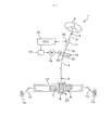
- FIG. 1 is a view schematically illustrating the configuration of an electric power steering system 1 according to an example embodiment of the invention.
- the electric power steering system 1 includes a steering shaft 3, a pinion shaft 5, a rack 7, and a rack shaft 8.
- the steering shaft 3 is connected to a steering operation member 2, which is a steering wheel, for example.
- the pinion shaft 5 is connected to the steering shaft 3 via an intermediate shaft 4.
- the rack 7 is in mesh with a pinion 6 provided at the pinion shaft 5.
- the rack shaft 8 is a steered shaft that extends in the lateral direction of a vehicle.
- the pinion shaft 5 and the rack shaft 8 constitute a steering mechanism 29 that is formed of a rack-and-pinion mechanism.
- the steering shaft 3 includes an input shaft 9 connected to the steering operation member 2, and an output shaft 10 connected to the intermediate shaft 4.
- the input shaft 9 and the output shaft 10 are coaxially connected to each other via a torsion bar 11 so as to be rotatable relative to each other.
- the rack shaft 8 is supported by a housing 12 via multiple bearings (not shown in the drawings) so as to be linearly movable back and forth.
- the both ends of the rack shaft 8 protrude out of the housing 12.
- the ends of the rack shaft 8 are linked, respectively, to steered wheels 14 via tie rods 13 and knuckle arms (not shown in the drawings).
- the steering shaft 3 rotates.
- the rotation of the steering shaft 3 is converted into a linear reciprocating motion of the rack shaft 8 via the pinion 6 and the rack 7.
- the steered wheels 14 are steered.
- the torsion bar 11 is twisted, which causes the input shaft 9 and the output shaft 10 to rotate relative to each other by a minute angle.
- a displacement due to the relative rotation is detected by a torque sensor 15 provided near the steering shaft 3.
- the output signals from the torque sensor 15 are input into an ECU 16 (Electronic Control Unit).
- the ECU 16 controls the driving of a steering operation assist electric motor 18 via a drive circuit 17 based on the value of the torque, the value of the vehicle speed detected by a vehicle speed sensor (not shown in the drawings), etc.
- the output from the electric motor 18 is transmitted to the output shaft 10 of the steering shaft 3 via a reduction unit 19.
- the force transmitted to the output shaft 10 is transmitted to the rack shaft 8 via the pinion shaft 5, etc., whereby the steering operation is assisted.
- the reduction unit 19 includes a worm shaft 20 and a worm wheel 21.
- the worm shaft 20 is a drive gear that is rotationally driven by the electric motor 18.
- the worm wheel 21 is a driven gear that is in mesh with the worm shaft 20.
- the worm wheel 21 is connected to the steering mechanism 29 via the output shaft 10 of the steering shaft 3, etc.
- FIG. 2 is a sectional view showing the electric motor 18, the reduction unit 19, and the structures near the reduction unit 19.
- the reduction unit 19 is housed in a housing 70.
- the electric motor 18 is supported by the housing 70.
- the housing 70 has a drive gear housing portion 71 and a driven gear housing portion 72, which are both cylindrical.
- the worm shaft 20 is housed in the drive gear housing portion 71.
- the worm wheel 21 is housed in the driven gear housing portion 72.
- the drive gear housing portion 71 and the driven gear housing portion 72 are formed as a single-piece member that is made of a metallic material, such as an aluminum alloy.
- An annular flange portion 73 is formed at an end of the drive gear housing portion 71.
- the annular flange portion 73 is formed integrally with the drive gear housing portion 71.
- a motor housing 18a of the electric motor 18 is attached to the annular flange portion 73 with fastening screws (not shown in the drawings).
- the electric motor 18 has the motor housing 18a and an output shaft 18b rotatably supported by the motor housing 18a.
- the output shaft 18b protrudes from the motor housing 18a toward the drive gear housing portion 71.
- the output shaft 18b is connected to the worm shaft 20 via a joint 50 such that drive force is transmittable between the output shaft 18b and the worm shaft 20.
- the worm shaft 20 has a first end portion 22, a second end portion 23, and a columnar worm 24 provided between the first end portion 22 and the second end portion 23 and having gear teeth.
- the first end portion 22 is connected to the output shaft 18b of the electric motor 18 via the joint 50 such that drive force is transmittable between the first end portion 22 and the output shaft 18b of the electric motor 18.
- the worm wheel 21 has an annular metallic core 27 and a synthetic-resin member 28.
- the metallic core 27 is fixed on the output shaft 10 so as to be rotatable together with the output shaft 10.
- the synthetic-resin member 28 surrounds the metallic core 27, and teeth are formed in the outer periphery of the synthetic-resin member 28.
- the metallic core 27 is inserted into a mold, for example, when resin molding is performed to form the synthetic-resin member 28.
- the metallic core 27 is connected to the output shaft 10 of the steering shaft 3, for example, through press-fitting.
- the worm wheel 21 is rotatable together with the output shaft 10 but axially immovable relative to the output shaft 10.
- a first bearing 31 is provided at the first end portion 22 of the worm shaft 20.
- a second bearing 32 is provided at the second end portion 23 of the worm shaft 20.
- the first bearing 31 and the second bearing 32 are, for example, rolling bearings such as deep groove ball bearings.
- the worm shaft 20 is rotatably supported by the drive gear housing portion 71 of the housing 70 via the first bearing 31 and the second bearing 32.
- the worm shaft 20 is pivotable about the first bearing 31 in a pivoting direction A1.
- the second end portion 23 of the worm shaft 20 is elastically urged in an urging direction B2, which is a direction in which a distance (inter-axis distance) K1 between a central axis L1 of the worm shaft 20 and a central axis L2 of the worm wheel 21 decreases.
- the internal clearances in the first bearing 31 that supports the worm shaft 20 are eliminated. This suppresses generation of rattle (vibrations) in the first bearing 31.
- the internal clearances in the first bearing 31 are, for example, the radial clearances between rolling elements 31c and an inner ring 31a and the radial clearances between rolling elements 31c and an outer ring 31b.
- the worm shaft 20 is movable relative to the housing 70 in an axial direction S1. This reduces a reaction force that is transferred from the electric motor 18 to the worm shaft 20 during a period from when an operation of the steering operation member 2 is started until when driving of the electric motor 18 is started.
- the axial direction S1, radial direction Q1, and circumferential direction C1 of the worm shaft 20 will be simply referred to as "the axial direction S1", “the radial direction Q1”, and “the circumferential direction C1", respectively.
- FIG. 3 is an enlarged view of portions near the first bearing 31 shown in FIG. 2 .
- the first bearing 31 supports the first end portion 22 of the worm shaft 20 such that the worm shaft 20 is pivotable about the first bearing 31 in the pivoting direction A1.
- the first bearing 31 has the inner ring 31a, the outer ring 31 b, and the rolling elements (balls) 31 c.
- the inner ring 31 a of the first bearing 31 is fitted onto an outer periphery 22a of the first end portion 22.
- the inner ring 31 a is fitted onto the first end portion 22 through clearance fit, or the like, and is therefore movable relative to the worm shaft 20 in the axial direction S1.
- Two second elastic member units 33 and 34 are provided on the respective sides of the inner ring 31a of the first bearing 31.
- the outer ring 31b of the first bearing 31 is supported by a first bearing support portion (retention hole) 71a via a pressing member 35 press-fitted and thereby fixed onto the outer peripheral face of the outer ring 31b.
- the first bearing support portion 71 a is formed in the inner peripheral face of the drive gear housing portion 71.
- the pressing member 35 is a cylindrical collar made of metal (e.g., iron) and surrounding the first bearing 31.
- the pressing member 35 and the first bearing 31 are assembled into a sub-assembly 36.
- the first bearing 31 prepared as the sub-assembly 36 is fitted onto the first end portion 22 of the worm shaft 20.
- the pressing member 35 is fitted to the first bearing support portion 71a through clearance fit, or the like. Therefore, the pressing member 35 and the first bearing 31 are not subjected to any pressing force applied from the first bearing support portion 71a in the radial direction Q1.
- the drive gear housing portion 71 has an annular stepped portion 71c and a first snap ring 37 that are located on respective sides of the first bearing support portion 71 a in the axial direction S1.
- the first snap ring 37 is fixed in an annular grove formed in the inner peripheral face of the drive gear housing portion 71.
- the outer ring 31b of the first bearing 31 and the pressing member 35 are interposed, in the axial direction S1, between the annular stepped portion 71c and the first snap ring 37. Thus, movement of the outer ring 31b of the first bearing 31 and the pressing member 35 relative to the drive gear housing portion 71 in the axial direction S1 is restricted.
- FIG. 4 is a further enlarged view of the portions near the first bearing 31 shown in FIG. 3 .
- the rolling elements 31c of the first bearing 31 are interposed between a raceway groove 31d formed at the outer peripheral face of the inner ring 31a and a raceway groove 31e formed at the inner peripheral face of the outer ring 31b.
- Each rolling element 31c of the first bearing 31 is a ball having a predetermined diameter D1.
- a curvature radius R1 of the raceway groove 31d of the inner ring 31a of the first bearing 31 and a curvature radius R2 of the raceway groove 31e of the outer ring 31b of the first bearing 31 are both larger than 50% of the diameter D1 of each rolling element 31 c, in a cutting plane that includes the center of the rolling element 31 c and the central axis of the first bearing 31 (i.e., cutting plane shown in FIG. 4 ).
- the ratio of the curvature radius R1 of the raceway groove 31d of the inner ring 31a to the diameter D1 of the rolling element 31c (R1/D1) is larger than the ratio of the inner ring raceway groove curvature radius R10 to the rolling element diameter D10 (R10/D10, e.g., 51%), which is specified for standard bearings in JIS (Japanese Industrial Standards), etc.
- the curvature radius R1 of the raceway groove 31d of the inner ring 31a is set to 52% to 56% of the diameter D1 of the rolling element 31c (0.52D1 ⁇ R1 ⁇ 0.56D1).
- the curvature radius R1 is less than 52% of the diameter D1 (R1 ⁇ 0.52D1), an amount by which the inner ring 31a is allowed, through rotational movement with respect to the rolling elements 31c, to oscillate relative to the outer ring 31b may be insufficient. Further, if the curvature radius R1 is larger than 56% of the diameter D1 (0.56D1 ⁇ R1), the depth of the raceway groove 31d of the inner ring 31a is too small to securely hold the rolling elements 31c. This may increase the possibility that the rolling elements 31c will come out of the raceway groove 31d of the inner ring 31a. More preferably, the curvature radius R1 is 52.5% of the diameter D1 or larger. Further, the curvature radius R1 may be 75% of the diameter D 1 or smaller.
- the ratio of the curvature radius R2 of the raceway groove 31e of the outer ring 31 b to the diameter D 1 of the rolling element 31 c (R2/D 1) is larger than the ratio of the outer ring raceway groove curvature radius R20 to the rolling element diameter D10 (R20/D10, e.g., 53%), which is specified for standard bearings in JIS (Japanese Industrial Standards), etc.
- the curvature radius R2 of the raceway groove 31e of the outer ring 31b is set to 54% to 58% of the diameter D1 of the rolling element 31c (0.54D1 ⁇ R2 ⁇ 0.58D1).
- the curvature radius R2 is smaller than 54% of the diameter D1 (R2 ⁇ 0.54D1), an amount by which the outer ring 31b is allowed, through rotational movement with respect to the rolling elements 31c, to oscillate relative to the inner ring 31a may be insufficient. Further, if the curvature radius R2 is larger than 58% of the diameter D1 (0.58D1 ⁇ R2), the depth of the raceway groove 31e of the outer ring 31b is too small to securely hold the rolling elements 31c. This may increase the possibility that the rolling elements 31c will come out of the raceway groove 31e of the outer ring 31b. More preferably, the curvature radius R2 is 53.5% of the diameter D1 or larger. Further, the curvature radius R2 may be 85% of the diameter D1 or smaller.
- the curvature radius R2 of the raceway groove 31e of the outer ring 31b is larger than the curvature radius R1 of the raceway groove 31d of the inner ring 31a (R1 ⁇ R2).
- the inner ring 31a is able to more smoothly oscillate relative to the outer ring 31b as the worm shaft 20 pivots.
- the inner ring 31a of the first bearing 31 is allowed to oscillate relative to the outer ring 31b by a large amount in the pivoting direction A1.
- the pivoting direction A1 of the worm shaft 20 includes both the clockwise and counterclockwise directions about the first bearing 31 on a plane perpendicular to the central axis L2 of the worm wheel 21.
- the inner diameter of the pressing member 35 (i.e., the diameter measured at the inner peripheral face of the pressing member 35) is smaller than the outer diameter of the outer ring 31b of the first bearing 31 when the pressing member 35 is not fixed onto the first bearing 31.
- the pressing member 35 elastically presses the outer ring 31b inward in the radial direction Q1.
- the raceway groove 31e of the outer ring 31 b, the rolling elements 31 c, and the raceway groove 31 d of the inner ring 31 a elastically press against each other in the radial direction Q1.
- the internal clearances in the first bearing 31 are eliminated, more specifically, "negative clearances" are created.
- the first bearing 31 is arranged, in the axial direction S1, between a pair of opposed portions 41 and 42 provided on the worm shaft 20.
- the opposed portion 41 is provided at a second snap ring 38 fixed in an annular groove at the first end portion 22 of the worm shaft 20. More specifically, the opposed portion 41 is annular and provided at one side face of the second snap ring 38.
- the opposed portion 42 is annular and provided at an annular stepped portion formed between the first end portion 22 and worm 24of the worm shaft 20.
- the second elastic member units 33 and 34 are located between the opposed portions 41 and 42 and arranged on respective sides of the first bearing 31. More specifically, the second elastic member unit 33 is arranged between the inner ring 31a of the first bearing 31 and the opposed portion 41. Also, the second elastic member unit 34 is arranged between the inner ring 31a of the first bearing 31 and the opposed portion 42.
- the second elastic member units 33 and 34 are provided to allow the worm shaft 20 to elastically move relative to the housing 70 in the axial direction S1. Further, the second elastic member units 33 and 34 also serve to damp and absorb the vibration of the worm 24 when vibrating force is input into the worm shaft 20 in the axial direction S1.
- the second elastic member unit 33 has a pair of side plates 61 and 62 arranged in the axial direction S1 and a second elastic member 63 interposed between the two side plates 61 and 62.
- the side plates 61 and 62 are each made from a metallic plate.
- the side plate 61 is annular, and is received by the opposed portion 41.
- a stopper portion 64 that extends toward the side plate 62 is formed at the side plate 61.
- the side plate 62 is annular, and is abutted on and thus received by a side face 31f, located on one side, of the inner ring 31 a of the first bearing 31.
- the second elastic member 63 is made of an elastic material (e.g., rubber) and is annular.
- the second elastic member 63 is joined to the side plate 61 by cure adhesion, for example. Further, the second elastic member 63 is joined also to the side plate 62 by cure adhesion, for example.
- the second elastic member 63 is arranged between the opposed portion 41 and the first bearing 31.
- the second elastic member unit 34 has a pair of side plates 65 and 66 arranged in the axial direction S 1 and a second elastic member 67 interposed between the two side plates 65 and 66.
- the side plates 65 and 66 are each made from a metallic plate.
- the side plate 65 is annular, and is received by the opposed portion 42.
- a stopper portion 68 that extends toward the side plate 66 is formed at the side plate 65.
- the side plate 66 is annular, and is abutted on and thus received by a side face 31 g, located on the other side, of the inner ring 31 a of the first bearing 31.
- the second elastic member 67 is made of the same material as the second elastic member 63 and is annular.
- the second elastic member 67 is joined to the side plate 65 by cure adhesion, for example. Further, the second elastic member 67 is joined also to the side plate 66 by cure adhesion, for example.
- the second elastic member 67 is arranged between the opposed portion 42 and the first bearing 31.
- the stopper portion 68 contacts the side plate 66, when the second elastic member 67 is compressed up to a certain degree. Thus, excessive compression of the second elastic member 67 is prevented.
- the elastic members 63 and 67 are elastically compressed when the electric power steering system 1 structured as described above is in an initial operation state.
- the elastic members 63 and 67 elastically deform to damp and absorb the vibration.
- the second bearing 32 has an inner ring 32a, an outer ring 32b, and rolling elements 32c.
- the inner ring 32a of the second bearing 32 is fitted onto the outer periphery of the second end portion 23.
- One end face of the inner ring 32a is received by an annular stepped portion 20b formed between the second end portion 23 and the worm 24.
- the outer ring 32b of the second bearing 32 is supported, via a first elastic member 45, on a second bearing support portion 71b formed in the inner peripheral face of the drive gear housing portion 71.
- the second bearing support portion 71b is a long hole that is long in an opposing direction B1 shown in FIG. 2 .
- the second bearing 32 and the second end portion 23 are movable relative to the drive gear housing portion 71 in the opposing direction B1 in which the central axis L1 of the worm shaft 20 and the central axis L2 of the worm wheel 21 are opposed to each other.
- the first elastic member 45 is a leaf spring that is manufactured by pressing an elongated metal piece.
- the first elastic member 45 has an arc-shaped body 46 and an elastic tongue 47 that extends from the body 46.
- the body 46 is fitted onto the outer peripheral face of the outer ring 32b of the second bearing 32.
- the elastic tongue 47 is in contact with the second bearing support portion 71b and elastically compressed. This elastic compression produces an elastic reactive force with which the first elastic member 45 urges, via the second bearing 32, the second end portion 23 of the worm shaft 20 in the urging direction B2 that is one of the two directions along the opposing direction B1.
- the urging direction B2 is perpendicular to the central axis L1 of the worm shaft 20 and extends from the worm shaft 20 toward the worm wheel 21 (i.e., the direction in which the inter-axis distance K1 decreases) when the reduction unit 19 is viewed along the axial direction of the worm wheel 21.
- Multiple elastic projections 48 are formed at the body 46.
- the elastic projections 48 each extend radially inward from the body 46.
- the elastic projections 48 are received by an end wall 71d of the drive gear housing portion 71, and elastically urge the second bearing 32 toward the first bearing 31.
- the second bearing 32 is supported by the second bearing support portion 71b via the first elastic member 45 such that the second bearing 32 is allowed to be displaced in the direction in which the inter-axis distance K1 between the central axis of the worm shaft 20 and that of the worm wheel 21 increases and decreases (i.e., the opposing direction B1). Further, the worm shaft 20 is elastically urged, with respect to the first bearing 31 (the first end portion 22) as the pivot center, so as to reduce the inter-axis distance K1 between the central axis of the worm shaft 20 and that of the worm wheel 21. In this way, backlash between the worm 24 of the worm shaft 20 and the worm wheel 21 is kept zero.
- the joint 50 interconnects the worm shaft 20 and the output shaft 18b of the electric motor 18 such that drive force is transmittable between them while the worm shaft 20 is pivotable in the pivoting direction A1, that is, the worm shaft 20 is pivotable about the first bearing 31.
- the joint 50 includes a first coupling member 51, a second coupling member 52, and an elastic member 53.
- the first coupling member 51 is connected to the output shaft 18b of the electric motor 18 such that the first coupling member 51 is rotatable together with the output shaft 18b.
- the second coupling member 52 is connected to the first end portion 22 of the worm shaft 20 such that the second coupling member 52 is rotatable together with the first end portion 22 of the worm shaft 20.
- the elastic member 53 is interposed between the first coupling member 51 and the second coupling member 52, and transmits torque from the first coupling member 51 to the second coupling member 52.
- the first coupling member 51 has a first body 54 and a plurality of first coupling projections 55 (note that only one of the first coupling projections 55 is shown in FIG. 3 ).
- the first body 54 is secured to the output shaft 18b of the electric motor 18.
- the first coupling projections 55 project from the first body 54 toward the second coupling member 52.
- the first coupling projections 55 are equiangularly arranged along the circumference of the first body 54.
- the second coupling member 52 has a second body 58 and a plurality of second coupling projections 59.
- the second body 58 is secured to the first end portion 22 of the worm shaft 20.
- the second coupling projections 59 project from the second body 58 toward the first coupling member 51.
- the second coupling projections 59 are equiangularly arranged along the circumference of the second body 58.
- the first coupling projections 55 and the second coupling projections 59 are alternately arranged in the circumferential direction C1.
- the elastic member 53 is made of, for example, synthetic rubber or synthetic resin.
- the elastic member 53 has an annular third body 53a and a plurality of coupling arms 53b.
- the coupling arms 53b radially extend from the peripheral face of the third body 53a.
- the coupling arms 53b are each arranged between a corresponding one of the first coupling projections 55 and the second coupling projection 59 that is opposed, in the circumferential direction C1, to the same first coupling projection 55, thus preventing contacts between the first coupling projections 55 and the second coupling projections 59.
- the second coupling member 52 is moved so as to be tilted relative to the first coupling member 51 while elastically deforming the elastic member 53.
- the joint 50 interconnects the output shaft 18b of the electric motor 18 and the first end portion 22 of the worm shaft 20 such that torque is transmittable between them and such that the worm shaft 20 is pivotable in the pivoting direction A1.
- the curvature radius R1 of the raceway groove 31d and the curvature radius R2 of the raceway groove 31e in the first bearing 31 are set to be larger than 50% of the diameter D 1 of each rolling element 31c to allow the worm shaft 20 to pivot about the first end portion 22.
- the worm shaft 20 is allowed to pivot about the first bearing 31 by a sufficiently large amount. Therefore, even if wear occurs in the meshing region 26 where the worm shaft 20 and the worm wheel 21 mesh with each other, the worm shaft 20, urged by the first elastic member 45, is able to sufficiently pivot. Thus, it is possible to maintain the state where backlash between the worm shaft 20 and the worm wheel 21 is eliminated. In this way, it is possible to suppress occurrence of rattle (vibrations) between the worm shaft 20 and the worm wheel 21 for a long period of time.
- the first bearing 31 is movable in the axial direction S 1 relative to the two opposed portions 41 and 42 of the worm shaft 20.
- the reaction force transferred to the steering operation member 2 via the worm shaft 20, the worm wheel 21, and the steering shaft 3 is small.
- a steering operation load imposed on the driver is sufficiently reduced.
- the curvature radius R1 of the raceway groove 31d and the curvature radius R2 of the raceway groove 31e are made large to reduce the loads placed on the outer ring 31b due to oscillation of the inner ring 31a, which makes it easier for the worm shaft 20 to move.
- the steering operation load placed on the driver is further reduced.
- negative internal clearances are created in the first bearing 31 (i.e., the internal clearances are eliminated in the first bearing 31) by, using the pressing member 35, pressing the inner ring 31a, the outer ring 31b, and the rolling elements 31c of the first bearing 31 in the radial direction Q1.
- This prevents the contact noise that would occur when the rolling elements 31c hit the raceway grooves 31 d and 31e if the first bearing 31 had internal clearances therein, that is, the rattling noise (bearing rattling noise) that would occur due to rattle in the first bearing 31.
- the pressing member 35 does not hinder the oscillation of the inner ring 31a of the first bearing 31 relative to the outer ring 31b, unlike the case where the internal clearances are eliminated by pressing the first bearing 31 in the axial direction S1.
- the first bearing 31 can be fitted onto the worm shaft 20 just by attaching the sub-assembly 36, which is assembled in advance by attaching the pressing member 35 on the first bearing 31, onto the worm shaft 20.
- first bearing 31 and the pressing member 35 can be easily fitted onto the worm shaft 20 just by fitting the sub-assembly 36, which is assembled by press-fitting the pressing member 35 onto the outer ring 31b of the first bearing 31, to the first end portion 22 of the worm shaft 20. Further, the pressing member 35 is fitted in the first bearing support portion 71a of the housing 70 through clearance fit. With this structure, the internal clearance state in the first bearing 31 does not change when the pressing member 35 and the first bearing 31 are together set in the first bearing support portion 71 a, unlike the case where the first bearing support portion 71a is a press-fit hole and the pressing member 35 and the first bearing 31 are press-fit into the press-fit hole.
- the second elastic members 63 and 67 which are provided on the respective sides of the first bearing 31, reliably damp and absorb the vibration of the worm shaft 20 in the axial direction S1.
- force reactive force
- the reactive force acts as a force which causes the worm wheel 21 in mesh with the worm shaft 20 to vibrate at a high frequency in the circumferential direction of the worm wheel 21.
- this force may cause the worm shaft 20 to vibrate in the axial direction S1.
- the second elastic members 63 and 67 which are provided on the respective sides of the first bearing 31, reliably damp and absorb the vibration of the worm shaft 20.
- setting the curvature radius R1 of the raceway groove 31d of the inner ring 31a of the first bearing 31 to at least 52% of the diameter D1 of each rolling element 31c allows the inner ring 31a to oscillate, through rotational movement of the inner ring 31a with respect to the rolling elements 31c, relative to the outer ring 31b by a sufficient amount. Further, setting the curvature radius R1 of the raceway groove 31d of the inner ring 31a of the first bearing 31 to at most 56% of the diameter D1 of each rolling element 31c achieves a sufficiently large depth of the raceway groove 31d of the inner ring 31 a, which enables the rolling elements 31c to be securely held by the inner ring 31a.
- setting the curvature radius R2 of the raceway groove 31e of the outer ring 31b of the first bearing 31 to at least 54% of the diameter D1 of each rolling element 31c allows the outer ring 31b to oscillate, through rotational movement of the outer ring 31 b with respect to the rolling elements 31 c, relative to the inner ring 31a by a sufficient amount. Further, setting the curvature radius R2 of the raceway groove 31e of the outer ring 31b of the first bearing 31 to at most 58% of the diameter D1 of each rolling element 31 c achieves a sufficiently large depth of the raceway groove 31e of the outer ring 31b, which enables the rolling elements 31c to be securely held by the outer ring 31b.
- a pressing member 35A may be fitted to the inner ring 31a of the first bearing 31 as described below.
- the differences from the example embodiment illustrated in FIGs. 1 to 4 will be mainly described, and the structural elements identical to those in the example embodiment illustrated in FIGs. 1 to 4 will be denoted using the same reference numerals and their descriptions will be omitted.
- the pressing member 35A is press-fitted and thereby fixed onto the inner peripheral face of the inner ring 31a of the first bearing 31.
- the outer diameter of the pressing member 35A i.e., the diameter measured at the outer peripheral face of the pressing member 35A
- the pressing member 35A elastically presses the inner ring 31 a of the first bearing 31 outward in the radial direction Q1.
- the raceway groove 31 d of the inner ring 31 a, the rolling elements 31 c, and the raceway groove 31e of the outer ring 31b are elastically pressed against each other in the radial direction Q1.
- the internal clearances in the first bearing 31 are eliminated, more specifically, "negative clearances" are created.
- the pressing member 35A is fitted onto the first end portion 22 of the worm shaft 20 through clearance fit, and is movable relative to the worm shaft 20 in the axial direction S1.
- the inner ring 31a of the first bearing 31 and the pressing member 35A are interposed, in the axial direction S1, between the side plate 62 of the second elastic member unit 33 and the side plate 66 of the second elastic member unit 34.
- the outer ring 31b of the first bearing 31 is directly fitted to the first bearing support portion 71a through clearance fit.
- the pressing member 35A and the first bearing 31 are assembled into a sub-assembly 36A.
- the first bearing 31 prepared as the sub-assembly 36A is fitted onto the first end portion 22 of the worm shaft 20.
- the second elastic members 63 and 67 are interposed, in the axial direction S1, between the two opposed portions 41 and 42 provided on the worm shaft 20 in the example embodiment illustrated in FIGs. 1 to 4 and the example embodiment illustrated in FIG. 5 , it is to be noted that invention is not limited to these structures.
- second elastic members 63B and 67B are interposed in the axial direction S1 between two opposed portions 41B and 42B provided at the housing 70.
- the opposed portion 41B is an annular portion provided at one side face of the first snap ring 37, while the opposed portion 42B is an annular portion provided at the annular stepped portion 71c of the drive gear housing portion 71.
- a second elastic member unit 33B as one of two second elastic member units is arranged between the opposed portion 41B and the outer ring 31b of the first bearing 31, while a side plate 61B as one of two side plates of the second elastic member unit 33B is received by the opposed portion 41B and a side plate 62B is received by a side face 31h, located on one side, of the outer ring 31b of the first bearing 31.
- the second elastic member unit 34B is arranged between the opposed portion 42B and the outer ring 31b of the first bearing 31.
- a side plate 65B as one of two side plates of the second elastic member unit 34B is received by the opposed portion 42B, while a side plate 66b is received by a side face 31j, located on the other side, of the outer ring 31b of the first bearing 31.
- the outer ring 31b of the first bearing 31 is fitted in the first bearing support portion 71a through clearance fit, and thus is movable relative to the housing 70 in the axial direction S1.
- the inner ring 31 a of the first bearing 31 is fitted onto the first end portion 22 of the worm shaft 20. Because the inner ring 31 a is press-fitted and thereby fixed onto the first end portion 22, the movement of the inner ring 31a relative to the worm shaft 20 in the axial direction S 1 is restricted. With this structure, as the worm shaft 20 vibrates (moves) relative to the housing 70 in the axial direction S1, the first bearing 31 concurrently vibrates in the axial direction S1, and the second elastic member units 63B and 67B elastically deform to damp and absorb the vibration.
- the pressing member 35 is fixed on the outer ring 31b of the first bearing 31 in the example embodiment illustrated in FIG. 6
- the pressing member 35A may be used in place of the pressing member 35 as shown in FIG. 7 .
- the pressing member 35A is press-fitted and thus fixed at its inner peripheral face onto the first end portion 22 of the worm shaft 20, and is press-fitted and thus fixed at its outer peripheral face to the inner peripheral face of the inner ring 31 a of the first bearing 31.
- the outer ring 31b of the first bearing 31 is fitted in the first bearing support portion 71a through clearance fit, such that the outer ring 31b is supported so as to be movable in the axial direction S1.
- Other structural features are the same as those in the example embodiment illustrated in FIG. 6 .
- the second elastic member units 33, 34, 33B, and 34B may be constituted only of the elastic member 63, 67, 63B, or 67B, respectively.
- the second elastic members 63 and 67 are each joined to the inner ring 31a of the first bearing 31 and a corresponding one of the two opposed portions 41 and 42 using an adhesive, or the like.
- the second elastic members 63B and 67B are each joined to the outer ring 31b of the first bearing 31 and a corresponding one of the two opposed portions 41B and 42B using an adhesive, or the like.
Abstract
Description
- The invention relates to an electric power steering system.
- In an electric power steering system in which an output from an electric motor is transmitted to a steering mechanism via a reduction mechanism, a worm reduction mechanism may be used as the reduction mechanism (for example, refer to paragraphs 0035, 0037, and 0038 of Japanese Patent Application Publication No.
2004-301265 - With the structure described above, the worm shaft is tilted about the one end portion toward the worm wheel side, thereby eliminating the backlash at a meshing portion where the worm shaft and the worm wheel mesh with each other. Further, when an axial load acting in the axial direction of the worm shaft is applied from the worm wheel to the worm shaft, the inner and outer rings of the ball bearing elastically deflect, allowing the worm shaft to slightly move in the axial direction. With this structure, the worm shaft is axially movable under a force transmitted from a steering wheel to the worm shaft via the worm wheel when the electric motor is not driven, for example, at the moment at which turning of the steering wheel is started. Accordingly, a resistive force that the worm shaft receives from the electric motor when the electric motor is not driven is smaller. As a result, it is possible to reduce a steering operation load that is placed on the driver when the electric motor is not driven.
- Usually, there are internal clearances in a ball bearing. If the internal clearances are too large, when a worm shaft moves in the axial direction, an inner ring of the bearing moves in the axial direction together with the worm shaft. Then, balls of the bearing hit the inner and outer rings, and consequently contact noise is generated. On the other hand, if the internal clearances in the bearing are too small, the movement of the worm shaft is hindered excessively. More specifically, if the internal clearances in the bearing are too small, it is not possible to sufficiently move an end portion of the worm shaft, which is distant from a motor, toward a worm wheel. Thus, it is not possible to eliminate the backlash that is generated between the worm shaft and the worm wheel as the teeth of the worm shaft wear. Therefore, contact noise, due to the backlash, occurs when the worm shaft and the worm wheel hit each other.
- Accordingly, the axial internal clearances in a ball bearing need to be set to appropriate values that are neither too large nor too small, and therefore strict dimensional control over the ball bearing is required. This results in an increase in the manufacturing cost. Japanese Patent Application Publication No.
2004-301265 - With the structure described in Japanese Patent Application Publication No.
2004-301265 - In the structure described in Japanese Patent Application Publication No.
2004-301265 - It is an object of the invention to provide an electric power steering system that has a low noise level, is inexpensive, and is assembled with less effort, and that is able to sufficiently reduce a steering operation load placed on a driver.
- An aspect of the invention relates to an electric power steering system. The electric power steering system includes: a worm shaft that has a first end portion and a second end portion, and that is connected to an electric motor; a worm wheel that meshes with the worm shaft, and that is connected to a steering mechanism; a housing that houses the worm shaft and the worm wheel; a first bearing that rotatably supports the first end portion, and that has an inner ring having a raceway groove, an outer ring having a raceway groove, and rolling elements interposed between the raceway grooves, wherein curvature radii of the raceway grooves in the first bearing are each larger than 50% of a diameter of each of the rolling elements, whereby the worm shaft is allowed to pivot about the first end portion, and the first bearing is opposed, in an axial direction of the worm shaft, to an opposed portion provided at the housing or the worm shaft and is movable relative to the opposed portion in the axial direction; a second bearing that rotatably supports the second end portion; a first elastic member that elastically urges the second bearing in a direction in which an inter-axis distance between a central axis of the worm shaft and a central axis of the worm wheel decreases; an annular pressing member that is fitted to the first bearing and radially presses the first bearing to cause the raceway groove of the inner ring, the raceway groove of the outer ring, and the rolling elements to press against each other; and a second elastic member that is arranged between the opposed portion and the first bearing and elastically deforms as the worm shaft moves relative to the housing in the axial direction.
- The foregoing and further features and advantages of the invention will become apparent from the following description of example embodiments with reference to the accompanying drawings, wherein like numerals are used to represent like elements and wherein:
-
FIG. 1 is a view schematically illustrating the configuration of an electric power steering system according to an example embodiment of the invention; -
FIG. 2 is a sectional view showing an electric motor and a reduction unit, and the structures near the reduction unit; -
FIG. 3 is an enlarged view of portions near a first bearing shown inFIG. 2 ; -
FIG. 4 is a further enlarged view of the portions near the first bearing shown inFIG. 3 ; -
FIG. 5 is a sectional view showing a main part of the structure according to another example embodiment of the invention; -
FIG. 6 is a sectional view showing a main part of the structure according to another example embodiment of the invention; and -
FIG. 7 is a sectional view showing a main part of the structure according to another example embodiment of the invention. - Hereafter, example embodiments of the invention will be described in detail with reference to the accompanying drawings.
FIG. 1 is a view schematically illustrating the configuration of an electricpower steering system 1 according to an example embodiment of the invention. Referring toFIG. 1 , the electricpower steering system 1 includes asteering shaft 3, apinion shaft 5, arack 7, and arack shaft 8. Thesteering shaft 3 is connected to asteering operation member 2, which is a steering wheel, for example. Thepinion shaft 5 is connected to thesteering shaft 3 via anintermediate shaft 4. Therack 7 is in mesh with apinion 6 provided at thepinion shaft 5. Therack shaft 8 is a steered shaft that extends in the lateral direction of a vehicle. Thepinion shaft 5 and therack shaft 8 constitute asteering mechanism 29 that is formed of a rack-and-pinion mechanism. - The
steering shaft 3 includes an input shaft 9 connected to thesteering operation member 2, and anoutput shaft 10 connected to theintermediate shaft 4. The input shaft 9 and theoutput shaft 10 are coaxially connected to each other via atorsion bar 11 so as to be rotatable relative to each other. Therack shaft 8 is supported by ahousing 12 via multiple bearings (not shown in the drawings) so as to be linearly movable back and forth. The both ends of therack shaft 8 protrude out of thehousing 12. The ends of therack shaft 8 are linked, respectively, to steeredwheels 14 viatie rods 13 and knuckle arms (not shown in the drawings). - As a driver turns the
steering operation member 2, thesteering shaft 3 rotates. The rotation of thesteering shaft 3 is converted into a linear reciprocating motion of therack shaft 8 via thepinion 6 and therack 7. Thus, the steeredwheels 14 are steered. As the steering torque is input into thesteering operation member 2, thetorsion bar 11 is twisted, which causes the input shaft 9 and theoutput shaft 10 to rotate relative to each other by a minute angle. A displacement due to the relative rotation is detected by atorque sensor 15 provided near the steeringshaft 3. Thus, the torque acting on thesteering operation member 2 is detected. The output signals from thetorque sensor 15 are input into an ECU 16 (Electronic Control Unit). TheECU 16 controls the driving of a steering operation assistelectric motor 18 via adrive circuit 17 based on the value of the torque, the value of the vehicle speed detected by a vehicle speed sensor (not shown in the drawings), etc. - The output from the
electric motor 18 is transmitted to theoutput shaft 10 of thesteering shaft 3 via areduction unit 19. The force transmitted to theoutput shaft 10 is transmitted to therack shaft 8 via thepinion shaft 5, etc., whereby the steering operation is assisted. Thereduction unit 19 includes aworm shaft 20 and aworm wheel 21. Theworm shaft 20 is a drive gear that is rotationally driven by theelectric motor 18. Theworm wheel 21 is a driven gear that is in mesh with theworm shaft 20. Theworm wheel 21 is connected to thesteering mechanism 29 via theoutput shaft 10 of thesteering shaft 3, etc. -
FIG. 2 is a sectional view showing theelectric motor 18, thereduction unit 19, and the structures near thereduction unit 19. Referring toFIG. 2 , thereduction unit 19 is housed in ahousing 70. Theelectric motor 18 is supported by thehousing 70. Thehousing 70 has a drivegear housing portion 71 and a driven gear housing portion 72, which are both cylindrical. Theworm shaft 20 is housed in the drivegear housing portion 71. Theworm wheel 21 is housed in the driven gear housing portion 72. The drivegear housing portion 71 and the driven gear housing portion 72 are formed as a single-piece member that is made of a metallic material, such as an aluminum alloy. - An
annular flange portion 73 is formed at an end of the drivegear housing portion 71. Theannular flange portion 73 is formed integrally with the drivegear housing portion 71. Amotor housing 18a of theelectric motor 18 is attached to theannular flange portion 73 with fastening screws (not shown in the drawings). Theelectric motor 18 has themotor housing 18a and anoutput shaft 18b rotatably supported by themotor housing 18a. Theoutput shaft 18b protrudes from themotor housing 18a toward the drivegear housing portion 71. Theoutput shaft 18b is connected to theworm shaft 20 via a joint 50 such that drive force is transmittable between theoutput shaft 18b and theworm shaft 20. - The
worm shaft 20 has afirst end portion 22, asecond end portion 23, and acolumnar worm 24 provided between thefirst end portion 22 and thesecond end portion 23 and having gear teeth. Thefirst end portion 22 is connected to theoutput shaft 18b of theelectric motor 18 via the joint 50 such that drive force is transmittable between thefirst end portion 22 and theoutput shaft 18b of theelectric motor 18. Thus, the output from theelectric motor 18 is transmitted to theworm shaft 20. Theworm wheel 21 has an annularmetallic core 27 and a synthetic-resin member 28. Themetallic core 27 is fixed on theoutput shaft 10 so as to be rotatable together with theoutput shaft 10. The synthetic-resin member 28 surrounds themetallic core 27, and teeth are formed in the outer periphery of the synthetic-resin member 28. Themetallic core 27 is inserted into a mold, for example, when resin molding is performed to form the synthetic-resin member 28. Themetallic core 27 is connected to theoutput shaft 10 of thesteering shaft 3, for example, through press-fitting. Thus, theworm wheel 21 is rotatable together with theoutput shaft 10 but axially immovable relative to theoutput shaft 10. - A
first bearing 31 is provided at thefirst end portion 22 of theworm shaft 20. Asecond bearing 32 is provided at thesecond end portion 23 of theworm shaft 20. Thefirst bearing 31 and thesecond bearing 32 are, for example, rolling bearings such as deep groove ball bearings. Theworm shaft 20 is rotatably supported by the drivegear housing portion 71 of thehousing 70 via thefirst bearing 31 and thesecond bearing 32. - The
worm shaft 20 is pivotable about thefirst bearing 31 in a pivoting direction A1. Thesecond end portion 23 of theworm shaft 20 is elastically urged in an urging direction B2, which is a direction in which a distance (inter-axis distance) K1 between a central axis L1 of theworm shaft 20 and a central axis L2 of theworm wheel 21 decreases. This suppresses generation of backlash in a meshingregion 26 where theworm 24, serving as the gear teeth portion of theworm shaft 20, and theworm wheel 21 mesh with each other. In the electricpower steering system 1, the internal clearances in thefirst bearing 31 that supports theworm shaft 20 are eliminated. This suppresses generation of rattle (vibrations) in thefirst bearing 31. The internal clearances in thefirst bearing 31 are, for example, the radial clearances between rollingelements 31c and aninner ring 31a and the radial clearances between rollingelements 31c and anouter ring 31b. - Further, the
worm shaft 20 is movable relative to thehousing 70 in an axial direction S1. This reduces a reaction force that is transferred from theelectric motor 18 to theworm shaft 20 during a period from when an operation of thesteering operation member 2 is started until when driving of theelectric motor 18 is started. In the following, the axial direction S1, radial direction Q1, and circumferential direction C1 of theworm shaft 20 will be simply referred to as "the axial direction S1", "the radial direction Q1", and "the circumferential direction C1", respectively. -
FIG. 3 is an enlarged view of portions near thefirst bearing 31 shown inFIG. 2 . Referring toFIG. 3 , thefirst bearing 31 supports thefirst end portion 22 of theworm shaft 20 such that theworm shaft 20 is pivotable about thefirst bearing 31 in the pivoting direction A1. Thefirst bearing 31 has theinner ring 31a, theouter ring 31 b, and the rolling elements (balls) 31 c. Theinner ring 31 a of thefirst bearing 31 is fitted onto anouter periphery 22a of thefirst end portion 22. Theinner ring 31 a is fitted onto thefirst end portion 22 through clearance fit, or the like, and is therefore movable relative to theworm shaft 20 in the axial direction S1. Two secondelastic member units inner ring 31a of thefirst bearing 31. - The
outer ring 31b of thefirst bearing 31 is supported by a first bearing support portion (retention hole) 71a via a pressingmember 35 press-fitted and thereby fixed onto the outer peripheral face of theouter ring 31b. The firstbearing support portion 71 a is formed in the inner peripheral face of the drivegear housing portion 71. The pressingmember 35 is a cylindrical collar made of metal (e.g., iron) and surrounding thefirst bearing 31. The pressingmember 35 and thefirst bearing 31 are assembled into asub-assembly 36. During assembly of the electricpower steering system 1, thefirst bearing 31 prepared as the sub-assembly 36 is fitted onto thefirst end portion 22 of theworm shaft 20. - The pressing
member 35 is fitted to the firstbearing support portion 71a through clearance fit, or the like. Therefore, the pressingmember 35 and thefirst bearing 31 are not subjected to any pressing force applied from the firstbearing support portion 71a in the radial direction Q1. The drivegear housing portion 71 has an annular steppedportion 71c and afirst snap ring 37 that are located on respective sides of the firstbearing support portion 71 a in the axial direction S1. Thefirst snap ring 37 is fixed in an annular grove formed in the inner peripheral face of the drivegear housing portion 71. Theouter ring 31b of thefirst bearing 31 and the pressingmember 35 are interposed, in the axial direction S1, between the annular steppedportion 71c and thefirst snap ring 37. Thus, movement of theouter ring 31b of thefirst bearing 31 and the pressingmember 35 relative to the drivegear housing portion 71 in the axial direction S1 is restricted. -
FIG. 4 is a further enlarged view of the portions near thefirst bearing 31 shown inFIG. 3 . Referring toFIG. 4 , the rollingelements 31c of thefirst bearing 31 are interposed between araceway groove 31d formed at the outer peripheral face of theinner ring 31a and araceway groove 31e formed at the inner peripheral face of theouter ring 31b. Each rollingelement 31c of thefirst bearing 31 is a ball having a predetermined diameter D1. A curvature radius R1 of theraceway groove 31d of theinner ring 31a of thefirst bearing 31 and a curvature radius R2 of theraceway groove 31e of theouter ring 31b of thefirst bearing 31 are both larger than 50% of the diameter D1 of each rollingelement 31 c, in a cutting plane that includes the center of the rollingelement 31 c and the central axis of the first bearing 31 (i.e., cutting plane shown inFIG. 4 ). - Preferably, the ratio of the curvature radius R1 of the
raceway groove 31d of theinner ring 31a to the diameter D1 of the rollingelement 31c (R1/D1) is larger than the ratio of the inner ring raceway groove curvature radius R10 to the rolling element diameter D10 (R10/D10, e.g., 51%), which is specified for standard bearings in JIS (Japanese Industrial Standards), etc. Preferably, the curvature radius R1 of theraceway groove 31d of theinner ring 31a is set to 52% to 56% of the diameter D1 of the rollingelement 31c (0.52D1 ≤ R1 ≤ 0.56D1). If the curvature radius R1 is less than 52% of the diameter D1 (R1 < 0.52D1), an amount by which theinner ring 31a is allowed, through rotational movement with respect to the rollingelements 31c, to oscillate relative to theouter ring 31b may be insufficient. Further, if the curvature radius R1 is larger than 56% of the diameter D1 (0.56D1 < R1), the depth of theraceway groove 31d of theinner ring 31a is too small to securely hold the rollingelements 31c. This may increase the possibility that the rollingelements 31c will come out of theraceway groove 31d of theinner ring 31a. More preferably, the curvature radius R1 is 52.5% of the diameter D1 or larger. Further, the curvature radius R1 may be 75% of thediameter D 1 or smaller. - Preferably, the ratio of the curvature radius R2 of the
raceway groove 31e of theouter ring 31 b to thediameter D 1 of the rollingelement 31 c (R2/D 1) is larger than the ratio of the outer ring raceway groove curvature radius R20 to the rolling element diameter D10 (R20/D10, e.g., 53%), which is specified for standard bearings in JIS (Japanese Industrial Standards), etc. Preferably, the curvature radius R2 of theraceway groove 31e of theouter ring 31b is set to 54% to 58% of the diameter D1 of the rollingelement 31c (0.54D1 ≤ R2 ≤ 0.58D1). If the curvature radius R2 is smaller than 54% of the diameter D1 (R2 < 0.54D1), an amount by which theouter ring 31b is allowed, through rotational movement with respect to the rollingelements 31c, to oscillate relative to theinner ring 31a may be insufficient. Further, if the curvature radius R2 is larger than 58% of the diameter D1 (0.58D1 < R2), the depth of theraceway groove 31e of theouter ring 31b is too small to securely hold the rollingelements 31c. This may increase the possibility that the rollingelements 31c will come out of theraceway groove 31e of theouter ring 31b. More preferably, the curvature radius R2 is 53.5% of the diameter D1 or larger. Further, the curvature radius R2 may be 85% of the diameter D1 or smaller. - Further, preferably, the curvature radius R2 of the
raceway groove 31e of theouter ring 31b is larger than the curvature radius R1 of theraceway groove 31d of theinner ring 31a (R1 < R2). Thus, theinner ring 31a is able to more smoothly oscillate relative to theouter ring 31b as theworm shaft 20 pivots. Referring toFIG. 3 , due to the structure described above, theinner ring 31a of thefirst bearing 31 is allowed to oscillate relative to theouter ring 31b by a large amount in the pivoting direction A1. The pivoting direction A1 of theworm shaft 20 includes both the clockwise and counterclockwise directions about thefirst bearing 31 on a plane perpendicular to the central axis L2 of theworm wheel 21. - The inner diameter of the pressing member 35 (i.e., the diameter measured at the inner peripheral face of the pressing member 35) is smaller than the outer diameter of the
outer ring 31b of thefirst bearing 31 when the pressingmember 35 is not fixed onto thefirst bearing 31. Thus, when fixed on theouter ring 31 b of thefirst bearing 31, the pressingmember 35 elastically presses theouter ring 31b inward in the radial direction Q1. Thus, in thefirst bearing 31, theraceway groove 31e of theouter ring 31 b, the rollingelements 31 c, and theraceway groove 31 d of theinner ring 31 a elastically press against each other in the radial direction Q1. Thus, the internal clearances in thefirst bearing 31 are eliminated, more specifically, "negative clearances" are created. - The
first bearing 31 is arranged, in the axial direction S1, between a pair ofopposed portions worm shaft 20. The opposedportion 41 is provided at a second snap ring 38 fixed in an annular groove at thefirst end portion 22 of theworm shaft 20. More specifically, the opposedportion 41 is annular and provided at one side face of the second snap ring 38. On the other hand, the opposedportion 42 is annular and provided at an annular stepped portion formed between thefirst end portion 22 and worm 24of theworm shaft 20. - In the axial direction S1, the second
elastic member units opposed portions first bearing 31. More specifically, the secondelastic member unit 33 is arranged between theinner ring 31a of thefirst bearing 31 and the opposedportion 41. Also, the secondelastic member unit 34 is arranged between theinner ring 31a of thefirst bearing 31 and the opposedportion 42. - The second
elastic member units worm shaft 20 to elastically move relative to thehousing 70 in the axial direction S1. Further, the secondelastic member units worm 24 when vibrating force is input into theworm shaft 20 in the axial direction S1. The secondelastic member unit 33 has a pair ofside plates elastic member 63 interposed between the twoside plates side plates - The
side plate 61 is annular, and is received by the opposedportion 41. Astopper portion 64 that extends toward theside plate 62 is formed at theside plate 61. Theside plate 62 is annular, and is abutted on and thus received by aside face 31f, located on one side, of theinner ring 31 a of thefirst bearing 31. The secondelastic member 63 is made of an elastic material (e.g., rubber) and is annular. The secondelastic member 63 is joined to theside plate 61 by cure adhesion, for example. Further, the secondelastic member 63 is joined also to theside plate 62 by cure adhesion, for example. The secondelastic member 63 is arranged between theopposed portion 41 and thefirst bearing 31. - With the structure described above, the
stopper portion 64 contacts theside plate 62, when the secondelastic member 63 is compressed up to a certain degree. Thus, excessive compression of theelastic member 63 is prevented. The secondelastic member unit 34 has a pair ofside plates axial direction S 1 and a secondelastic member 67 interposed between the twoside plates side plates - The
side plate 65 is annular, and is received by the opposedportion 42. Astopper portion 68 that extends toward theside plate 66 is formed at theside plate 65. Theside plate 66 is annular, and is abutted on and thus received by aside face 31 g, located on the other side, of theinner ring 31 a of thefirst bearing 31. The secondelastic member 67 is made of the same material as the secondelastic member 63 and is annular. The secondelastic member 67 is joined to theside plate 65 by cure adhesion, for example. Further, the secondelastic member 67 is joined also to theside plate 66 by cure adhesion, for example. The secondelastic member 67 is arranged between theopposed portion 42 and thefirst bearing 31. - With the structure described above, the
stopper portion 68 contacts theside plate 66, when the secondelastic member 67 is compressed up to a certain degree. Thus, excessive compression of the secondelastic member 67 is prevented. As such, theelastic members power steering system 1 structured as described above is in an initial operation state. When theworm shaft 20 vibrates relative to thehousing 70 in the axial direction S1, theelastic members - Referring to
FIG. 2 , thesecond bearing 32 has aninner ring 32a, anouter ring 32b, and rollingelements 32c. Theinner ring 32a of thesecond bearing 32 is fitted onto the outer periphery of thesecond end portion 23. One end face of theinner ring 32a is received by an annular steppedportion 20b formed between thesecond end portion 23 and theworm 24. Theouter ring 32b of thesecond bearing 32 is supported, via a first elastic member 45, on a second bearing support portion 71b formed in the inner peripheral face of the drivegear housing portion 71. The second bearing support portion 71b is a long hole that is long in an opposing direction B1 shown inFIG. 2 . Thus, thesecond bearing 32 and thesecond end portion 23 are movable relative to the drivegear housing portion 71 in the opposing direction B1 in which the central axis L1 of theworm shaft 20 and the central axis L2 of theworm wheel 21 are opposed to each other. - The first elastic member 45 is a leaf spring that is manufactured by pressing an elongated metal piece. The first elastic member 45 has an arc-shaped
body 46 and anelastic tongue 47 that extends from thebody 46. Thebody 46 is fitted onto the outer peripheral face of theouter ring 32b of thesecond bearing 32. Theelastic tongue 47 is in contact with the second bearing support portion 71b and elastically compressed. This elastic compression produces an elastic reactive force with which the first elastic member 45 urges, via thesecond bearing 32, thesecond end portion 23 of theworm shaft 20 in the urging direction B2 that is one of the two directions along the opposing direction B1. - The urging direction B2 is perpendicular to the central axis L1 of the
worm shaft 20 and extends from theworm shaft 20 toward the worm wheel 21 (i.e., the direction in which the inter-axis distance K1 decreases) when thereduction unit 19 is viewed along the axial direction of theworm wheel 21. Multiple elastic projections 48 are formed at thebody 46. The elastic projections 48 each extend radially inward from thebody 46. The elastic projections 48 are received by anend wall 71d of the drivegear housing portion 71, and elastically urge thesecond bearing 32 toward thefirst bearing 31. - As described above, the
second bearing 32 is supported by the second bearing support portion 71b via the first elastic member 45 such that thesecond bearing 32 is allowed to be displaced in the direction in which the inter-axis distance K1 between the central axis of theworm shaft 20 and that of theworm wheel 21 increases and decreases (i.e., the opposing direction B1). Further, theworm shaft 20 is elastically urged, with respect to the first bearing 31 (the first end portion 22) as the pivot center, so as to reduce the inter-axis distance K1 between the central axis of theworm shaft 20 and that of theworm wheel 21. In this way, backlash between theworm 24 of theworm shaft 20 and theworm wheel 21 is kept zero. - Referring to
FIG. 3 , the joint 50 interconnects theworm shaft 20 and theoutput shaft 18b of theelectric motor 18 such that drive force is transmittable between them while theworm shaft 20 is pivotable in the pivoting direction A1, that is, theworm shaft 20 is pivotable about thefirst bearing 31. The joint 50 includes afirst coupling member 51, asecond coupling member 52, and anelastic member 53. Thefirst coupling member 51 is connected to theoutput shaft 18b of theelectric motor 18 such that thefirst coupling member 51 is rotatable together with theoutput shaft 18b. Thesecond coupling member 52 is connected to thefirst end portion 22 of theworm shaft 20 such that thesecond coupling member 52 is rotatable together with thefirst end portion 22 of theworm shaft 20. Theelastic member 53 is interposed between thefirst coupling member 51 and thesecond coupling member 52, and transmits torque from thefirst coupling member 51 to thesecond coupling member 52. - The
first coupling member 51 has afirst body 54 and a plurality of first coupling projections 55 (note that only one of thefirst coupling projections 55 is shown inFIG. 3 ). Thefirst body 54 is secured to theoutput shaft 18b of theelectric motor 18. Thefirst coupling projections 55 project from thefirst body 54 toward thesecond coupling member 52. Thefirst coupling projections 55 are equiangularly arranged along the circumference of thefirst body 54. Thesecond coupling member 52 has asecond body 58 and a plurality ofsecond coupling projections 59. Thesecond body 58 is secured to thefirst end portion 22 of theworm shaft 20. Thesecond coupling projections 59 project from thesecond body 58 toward thefirst coupling member 51. Thesecond coupling projections 59 are equiangularly arranged along the circumference of thesecond body 58. Thus, thefirst coupling projections 55 and thesecond coupling projections 59 are alternately arranged in the circumferential direction C1. - The
elastic member 53 is made of, for example, synthetic rubber or synthetic resin. Theelastic member 53 has an annularthird body 53a and a plurality of couplingarms 53b. The couplingarms 53b radially extend from the peripheral face of thethird body 53a. The couplingarms 53b are each arranged between a corresponding one of thefirst coupling projections 55 and thesecond coupling projection 59 that is opposed, in the circumferential direction C1, to the samefirst coupling projection 55, thus preventing contacts between thefirst coupling projections 55 and thesecond coupling projections 59. - As the
worm shaft 20 pivots in the pivoting direction A1, thesecond coupling member 52 is moved so as to be tilted relative to thefirst coupling member 51 while elastically deforming theelastic member 53. As such, the joint 50 interconnects theoutput shaft 18b of theelectric motor 18 and thefirst end portion 22 of theworm shaft 20 such that torque is transmittable between them and such that theworm shaft 20 is pivotable in the pivoting direction A1. According to this example embodiment, as described above, the curvature radius R1 of theraceway groove 31d and the curvature radius R2 of theraceway groove 31e in thefirst bearing 31 are set to be larger than 50% of thediameter D 1 of each rollingelement 31c to allow theworm shaft 20 to pivot about thefirst end portion 22. Thus, theworm shaft 20 is allowed to pivot about thefirst bearing 31 by a sufficiently large amount. Therefore, even if wear occurs in the meshingregion 26 where theworm shaft 20 and theworm wheel 21 mesh with each other, theworm shaft 20, urged by the first elastic member 45, is able to sufficiently pivot. Thus, it is possible to maintain the state where backlash between theworm shaft 20 and theworm wheel 21 is eliminated. In this way, it is possible to suppress occurrence of rattle (vibrations) between theworm shaft 20 and theworm wheel 21 for a long period of time. Thus, even if a reactive force is transmitted to the meshingregion 26, in which theworm shaft 20 and theworm wheel 21 mesh with each other, from the road surface via thesteering mechanism 29, and so on, when the vehicle is traveling on a rough road, or the like, the vibration of the worm wheel against the worm shaft, which may be caused by the reactive force, can be suppressed. Therefore, it is possible to suppress generation of rattling noise (rattling gear-contact noise) in the meshing region in which the worm shaft and the worm wheel mesh with each other. In addition, since the secondelastic members worm shaft 20, the rattling gear-contact noise is more reliably reduced. - Further, the
first bearing 31 is movable in theaxial direction S 1 relative to the twoopposed portions worm shaft 20. This allows theworm shaft 20 to move in the axial direction S1 by a sufficiently large amount. Therefore, theworm shaft 20 can sufficiently move in theaxial direction S 1 when an axial load acts on theworm shaft 20 as thesteering shaft 3 and theworm wheel 21 are rotated by an operation of thesteering operation member 2 by the driver. Accordingly, when theelectric motor 18 is not driven, for example, because the operation amount of thesteering operation member 2 is very small, application of the reaction force from theelectric motor 18 to theworm shaft 20 is suppressed. Therefore, the reaction force transferred to thesteering operation member 2 via theworm shaft 20, theworm wheel 21, and thesteering shaft 3 is small. Thus, a steering operation load imposed on the driver is sufficiently reduced. Further, the curvature radius R1 of theraceway groove 31d and the curvature radius R2 of theraceway groove 31e are made large to reduce the loads placed on theouter ring 31b due to oscillation of theinner ring 31a, which makes it easier for theworm shaft 20 to move. Thus, the steering operation load placed on the driver is further reduced. - Further, negative internal clearances are created in the first bearing 31 (i.e., the internal clearances are eliminated in the first bearing 31) by, using the pressing
member 35, pressing theinner ring 31a, theouter ring 31b, and the rollingelements 31c of thefirst bearing 31 in the radial direction Q1. This prevents the contact noise that would occur when the rollingelements 31c hit theraceway grooves first bearing 31 had internal clearances therein, that is, the rattling noise (bearing rattling noise) that would occur due to rattle in thefirst bearing 31. Further, the pressingmember 35 does not hinder the oscillation of theinner ring 31a of thefirst bearing 31 relative to theouter ring 31b, unlike the case where the internal clearances are eliminated by pressing thefirst bearing 31 in the axial direction S1. Further, thefirst bearing 31 can be fitted onto theworm shaft 20 just by attaching the sub-assembly 36, which is assembled in advance by attaching the pressingmember 35 on thefirst bearing 31, onto theworm shaft 20. - That is, it is not necessary to perform highly accurate dimensional matching between the inner diameter of the
inner ring 31a of thefirst bearing 31 and the outer diameter of theworm shaft 20 and then press-fit theinner ring 31 a of thefirst bearing 31 onto theworm shaft 20 so as to adjust the internal clearances in thefirst bearing 31 to appropriate values, which requires a lot of time and efforts. Therefore, the time, efforts, and cost required to assemble the electricpower steering system 1 can be reduced. Further, using a ball bearing as thefirst bearing 31 allows theworm shaft 20 to pivot about thefirst bearing 31 more reliably. - Further, the
first bearing 31 and the pressingmember 35 can be easily fitted onto theworm shaft 20 just by fitting the sub-assembly 36, which is assembled by press-fitting thepressing member 35 onto theouter ring 31b of thefirst bearing 31, to thefirst end portion 22 of theworm shaft 20. Further, the pressingmember 35 is fitted in the firstbearing support portion 71a of thehousing 70 through clearance fit. With this structure, the internal clearance state in thefirst bearing 31 does not change when the pressingmember 35 and thefirst bearing 31 are together set in the firstbearing support portion 71 a, unlike the case where the firstbearing support portion 71a is a press-fit hole and the pressingmember 35 and thefirst bearing 31 are press-fit into the press-fit hole. - Further, the second
elastic members first bearing 31, reliably damp and absorb the vibration of theworm shaft 20 in the axial direction S1. For example, when the vehicle is traveling on a very uneven rough road, or the like, if force (reactive force) is input from the road surface to the steeredwheels 14, thesteering mechanism 29, and theworm wheel 21, the reactive force acts as a force which causes theworm wheel 21 in mesh with theworm shaft 20 to vibrate at a high frequency in the circumferential direction of theworm wheel 21. Further, this force may cause theworm shaft 20 to vibrate in the axial direction S1. With the structure described above, however, even when theworm shaft 20 thus vibrates in the axial direction S1, the secondelastic members first bearing 31, reliably damp and absorb the vibration of theworm shaft 20. - Further, setting the curvature radius R1 of the
raceway groove 31d of theinner ring 31a of thefirst bearing 31 to at least 52% of the diameter D1 of each rollingelement 31c allows theinner ring 31a to oscillate, through rotational movement of theinner ring 31a with respect to the rollingelements 31c, relative to theouter ring 31b by a sufficient amount. Further, setting the curvature radius R1 of theraceway groove 31d of theinner ring 31a of thefirst bearing 31 to at most 56% of the diameter D1 of each rollingelement 31c achieves a sufficiently large depth of theraceway groove 31d of theinner ring 31 a, which enables the rollingelements 31c to be securely held by theinner ring 31a. Thus, the possibility that the rollingelements 31c will come out of theraceway groove 31d of theinner ring 31a is reliably reduced. As a result, the loads on the rollingelements 31c and theraceway groove 31d of theinner ring 31a are reduced, resulting in a longer life of thefirst bearing 31. - Further, setting the curvature radius R2 of the
raceway groove 31e of theouter ring 31b of thefirst bearing 31 to at least 54% of the diameter D1 of each rollingelement 31c allows theouter ring 31b to oscillate, through rotational movement of theouter ring 31 b with respect to the rollingelements 31 c, relative to theinner ring 31a by a sufficient amount. Further, setting the curvature radius R2 of theraceway groove 31e of theouter ring 31b of thefirst bearing 31 to at most 58% of the diameter D1 of each rollingelement 31 c achieves a sufficiently large depth of theraceway groove 31e of theouter ring 31b, which enables the rollingelements 31c to be securely held by theouter ring 31b. Thus, the possibility that the rollingelements 31c will come out of theraceway groove 31e of theouter ring 31b is reliably reduced. As a result, the loads on the rollingelements 31c and theraceway groove 31e of theouter ring 31b are reduced, resulting in a longer life of thefirst bearing 31. - In the meantime, it is to be understood that the invention is not limited to the foregoing example embodiment, but it may be implemented in various other forms and arrangements within the scope of the claims. For example, as shown in
FIG. 5 , a pressingmember 35A may be fitted to theinner ring 31a of thefirst bearing 31 as described below. In the following, the differences from the example embodiment illustrated inFIGs. 1 to 4 will be mainly described, and the structural elements identical to those in the example embodiment illustrated inFIGs. 1 to 4 will be denoted using the same reference numerals and their descriptions will be omitted. - The
pressing member 35A is press-fitted and thereby fixed onto the inner peripheral face of theinner ring 31a of thefirst bearing 31. The outer diameter of thepressing member 35A (i.e., the diameter measured at the outer peripheral face of thepressing member 35A) is larger than the inner diameter of theinner ring 31a of thefirst bearing 31 when thepressing member 35A is not fixed on thefirst bearing 31. Thus, when fixed on thefirst bearing 31, the pressingmember 35A elastically presses theinner ring 31 a of thefirst bearing 31 outward in the radial direction Q1. Thus, in thefirst bearing 31, theraceway groove 31 d of theinner ring 31 a, the rollingelements 31 c, and theraceway groove 31e of theouter ring 31b are elastically pressed against each other in the radial direction Q1. Thus, the internal clearances in thefirst bearing 31 are eliminated, more specifically, "negative clearances" are created. - The
pressing member 35A is fitted onto thefirst end portion 22 of theworm shaft 20 through clearance fit, and is movable relative to theworm shaft 20 in the axial direction S1. Theinner ring 31a of thefirst bearing 31 and thepressing member 35A are interposed, in the axial direction S1, between theside plate 62 of the secondelastic member unit 33 and theside plate 66 of the secondelastic member unit 34. Theouter ring 31b of thefirst bearing 31 is directly fitted to the firstbearing support portion 71a through clearance fit. - The
pressing member 35A and thefirst bearing 31 are assembled into asub-assembly 36A. During assembly of the electricpower steering system 1, thefirst bearing 31 prepared as thesub-assembly 36A is fitted onto thefirst end portion 22 of theworm shaft 20. Meanwhile, while the secondelastic members opposed portions worm shaft 20 in the example embodiment illustrated inFIGs. 1 to 4 and the example embodiment illustrated inFIG. 5 , it is to be noted that invention is not limited to these structures. - For example, the structure shown in
FIG. 6 may alternatively be used. Referring toFIG. 6 , secondelastic members opposed portions housing 70. Theopposed portion 41B is an annular portion provided at one side face of thefirst snap ring 37, while the opposedportion 42B is an annular portion provided at the annular steppedportion 71c of the drivegear housing portion 71. A secondelastic member unit 33B as one of two second elastic member units is arranged between theopposed portion 41B and theouter ring 31b of thefirst bearing 31, while aside plate 61B as one of two side plates of the secondelastic member unit 33B is received by the opposedportion 41B and aside plate 62B is received by a side face 31h, located on one side, of theouter ring 31b of thefirst bearing 31. - The second
elastic member unit 34B is arranged between theopposed portion 42B and theouter ring 31b of thefirst bearing 31. Aside plate 65B as one of two side plates of the secondelastic member unit 34B is received by the opposedportion 42B, while a side plate 66b is received by aside face 31j, located on the other side, of theouter ring 31b of thefirst bearing 31. Theouter ring 31b of thefirst bearing 31 is fitted in the firstbearing support portion 71a through clearance fit, and thus is movable relative to thehousing 70 in the axial direction S1. - The
inner ring 31 a of thefirst bearing 31 is fitted onto thefirst end portion 22 of theworm shaft 20. Because theinner ring 31 a is press-fitted and thereby fixed onto thefirst end portion 22, the movement of theinner ring 31a relative to theworm shaft 20 in theaxial direction S 1 is restricted. With this structure, as theworm shaft 20 vibrates (moves) relative to thehousing 70 in the axial direction S1, thefirst bearing 31 concurrently vibrates in the axial direction S1, and the secondelastic member units - While the pressing
member 35 is fixed on theouter ring 31b of thefirst bearing 31 in the example embodiment illustrated inFIG. 6 , the pressingmember 35A may be used in place of the pressingmember 35 as shown inFIG. 7 . In the example embodiment illustrated inFIG. 7 , unlike the example embodiment illustrated inFIG. 6 , the pressingmember 35A is press-fitted and thus fixed at its inner peripheral face onto thefirst end portion 22 of theworm shaft 20, and is press-fitted and thus fixed at its outer peripheral face to the inner peripheral face of theinner ring 31 a of thefirst bearing 31. Theouter ring 31b of thefirst bearing 31 is fitted in the firstbearing support portion 71a through clearance fit, such that theouter ring 31b is supported so as to be movable in the axial direction S1. Other structural features are the same as those in the example embodiment illustrated inFIG. 6 . - Further, the second
elastic member units elastic member elastic members inner ring 31a of thefirst bearing 31 and a corresponding one of the twoopposed portions elastic members outer ring 31b of thefirst bearing 31 and a corresponding one of the twoopposed portions
Claims (7)
- An electric power steering system, comprising:a worm shaft that has a first end portion and a second end portion, and that is connected to an electric motor;a worm wheel that meshes with the worm shaft, and that is connected to a steering mechanism;a housing that houses the worm shaft and the worm wheel;a first bearing that rotatably supports the first end portion, and that has an inner ring having a raceway groove, an outer ring having a raceway groove, and rolling elements interposed between the raceway grooves, wherein curvature radii of the raceway grooves in the first bearing are each larger than 50% of a diameter of each of the rolling elements, whereby the worm shaft is allowed to pivot about the first end portion, and the first bearing is opposed, in an axial direction of the worm shaft, to an opposed portion provided at the housing or the worm shaft and is movable relative to the opposed portion in the axial direction;a second bearing that rotatably supports the second end portion;a first elastic member that elastically urges the second bearing in a direction in which an inter-axis distance between a central axis of the worm shaft and a central axis of the worm wheel decreases;an annular pressing member that is fitted to the first bearing and radially presses the first bearing to cause the raceway groove of the inner ring, the raceway groove of the outer ring, and the rolling elements to press against each other; anda second elastic member that is arranged between the opposed portion and the first bearing and elastically deforms as the worm shaft moves relative to the housing in the axial direction.
- The electric power steering system according to claim 1, wherein:the first bearing is a ball bearing and the rolling elements are balls; andthe curvature radii of the raceway grooves are curvature radii as measured on a plane on which a central axis of the first bearing extends.
- The electric power steering system according to claim 1 or 2, wherein the pressing member is press-fitted and thereby fixed on an outer peripheral face of the outer ring of the first bearing.
- The electric power steering system according to claim 3, wherein the pressing member is fitted in a retention hole, formed in the housing, through clearance fit.
- The electric power steering system according to any one claims 1 to 4, wherein:the opposed portion includes a pair of opposed portions between which the first bearing is interposed in the axial direction; andthe second elastic member includes a pair of elastic members that are provided, respectively, between one of the opposed portions and the first bearing and between the other of the opposed portions and the first bearing.
- The electric power steering system according to any one claims 1 to 5, wherein the curvature radius of the raceway groove of the inner ring is set to 52% to 56% of the diameter of each of the rolling elements.
- The electric power steering system according to any one claims 1 to 6, wherein the curvature radius of the raceway groove of the outer ring is set to 54% to 58% of the diameter of each of the rolling elements.
Applications Claiming Priority (1)
| Application Number | Priority Date | Filing Date | Title |
|---|---|---|---|
| JP2010251068A JP5645070B2 (en) | 2010-11-09 | 2010-11-09 | Electric power steering device |
Publications (2)
| Publication Number | Publication Date |
|---|---|
| EP2450262A1 true EP2450262A1 (en) | 2012-05-09 |
| EP2450262B1 EP2450262B1 (en) | 2014-10-15 |
Family
ID=44905659
Family Applications (1)
| Application Number | Title | Priority Date | Filing Date |
|---|---|---|---|
| EP11187772.6A Active EP2450262B1 (en) | 2010-11-09 | 2011-11-03 | Electric power steering system |
Country Status (4)
| Country | Link |
|---|---|
| US (1) | US8459402B2 (en) |
| EP (1) | EP2450262B1 (en) |
| JP (1) | JP5645070B2 (en) |
| CN (1) | CN102530057B (en) |
Cited By (7)
| Publication number | Priority date | Publication date | Assignee | Title |
|---|---|---|---|---|
| DE102013003749A1 (en) | 2013-03-06 | 2014-09-11 | Thyssenkrupp Presta Aktiengesellschaft | Angularly movable bearing arrangement for pinions in reduction gears of electromechanical steering systems |
| EP2829458A1 (en) * | 2013-07-25 | 2015-01-28 | Jtekt Corporation | Electric power steering system |
| EP2689988A3 (en) * | 2012-07-27 | 2015-05-20 | Jtekt Corporation | Electric power steering system |
| KR20160002512A (en) * | 2014-06-30 | 2016-01-08 | 현대모비스 주식회사 | Motor driven power steering system |
| EP3135935A4 (en) * | 2014-04-23 | 2018-01-17 | NSK Ltd. | Bearing device, conveyance device, inspection device and machine tool |
| WO2018033459A1 (en) * | 2016-08-16 | 2018-02-22 | Thyssenkrupp Presta Ag | Rolling bearing for the mounting of a drive worm of an electromechanical power steering system of a motor vehicle |
| US10352357B2 (en) | 2014-04-23 | 2019-07-16 | Nsk Ltd. | Bearing device, conveying device, inspection device, and machine tool |
Families Citing this family (39)
| Publication number | Priority date | Publication date | Assignee | Title |
|---|---|---|---|---|
| EP2409043A4 (en) * | 2009-01-23 | 2013-05-22 | Skf Usa Inc | Bearing assembly for a power steering mechanism |
| DE102010002958A1 (en) * | 2010-03-17 | 2011-09-22 | Zf Lenksysteme Gmbh | Power steering |
| JP5618146B2 (en) * | 2010-12-24 | 2014-11-05 | 株式会社ジェイテクト | Electric power steering device |
| US9884642B2 (en) * | 2011-12-12 | 2018-02-06 | Toyota Jidosha Kabushiki Kaisha | Steering device |
| WO2013161845A1 (en) * | 2012-04-25 | 2013-10-31 | 株式会社ジェイテクト | Electric power steering device |
| DE102013223380A1 (en) * | 2013-01-10 | 2014-07-10 | Ford Global Technologies, Llc | Electric power steering for vehicles |
| US10787195B2 (en) * | 2013-05-22 | 2020-09-29 | Jtekt Corporation | Electric power steering system |
| KR101477906B1 (en) * | 2013-05-28 | 2014-12-30 | 주식회사 만도 | Reducer of Electric Power Steering Apparatus |
| CN104176113B (en) * | 2013-05-28 | 2018-01-23 | 上海汽车集团股份有限公司 | Gap of worm eliminating machine, electric boosting steering system and automobile |
| KR101477907B1 (en) * | 2013-05-29 | 2014-12-30 | 주식회사 만도 | Reducer of Electric Power Steering Apparatus |
| FR3007808B1 (en) * | 2013-06-28 | 2015-07-17 | Skf Ab | CAGE FOR BEARING, IN PARTICULAR FOR THE BEARING OF ELECTRIC POWER STEERING SYSTEM OF A MOTOR VEHICLE |
| JP5915606B2 (en) * | 2013-09-06 | 2016-05-11 | トヨタ自動車株式会社 | Control device for hybrid vehicle |
| JP6353258B2 (en) * | 2014-03-31 | 2018-07-04 | 日本電産サンキョー株式会社 | Bearing mechanism and motor device |
| KR102151110B1 (en) * | 2014-06-11 | 2020-09-02 | 현대모비스 주식회사 | Bearing bush |
| KR101560980B1 (en) * | 2014-06-23 | 2015-10-15 | 주식회사 만도 | Power Transmission Device of Electric Power Steering Apparatus |
| JP6108358B2 (en) * | 2014-07-23 | 2017-04-05 | 株式会社ショーワ | Worm biasing structure |
| KR102281681B1 (en) * | 2015-01-12 | 2021-07-27 | 주식회사 만도 | Reducer for vehicle |
| US9744987B2 (en) * | 2015-04-29 | 2017-08-29 | Steering Solutions Ip Holding Corporation | Worm shaft subassembly |
| DE102016211695A1 (en) | 2016-06-29 | 2018-01-04 | Ford Global Technologies, Llc | Transmission unit for a motor vehicle |
| DE202016103799U1 (en) | 2016-06-29 | 2016-07-27 | Ford Global Technologies, Llc | Transmission unit for a motor vehicle |
| DE102016211681B3 (en) * | 2016-06-29 | 2017-09-07 | Ford Global Technologies, Llc | Transmission unit for a motor vehicle |
| DE202016103675U1 (en) | 2016-06-29 | 2016-07-26 | Ford Global Technologies, Llc | Transmission unit for a motor vehicle |
| DE102016211706B3 (en) * | 2016-06-29 | 2017-12-14 | Ford Global Technologies, Llc | Transmission unit for a motor vehicle |
| DE202016103794U1 (en) | 2016-06-29 | 2016-07-29 | Ford Global Technologies, Llc | Transmission unit for a motor vehicle |
| DE102016211714B3 (en) * | 2016-06-29 | 2017-09-07 | Ford Global Technologies, Llc | Transmission unit for a motor vehicle |
| DE102016211707A1 (en) | 2016-06-29 | 2018-01-04 | Ford Global Technologies, Llc | Transmission unit for a motor vehicle |
| DE102016211682A1 (en) | 2016-06-29 | 2018-01-04 | Ford Global Technologies, Llc | Transmission unit for a motor vehicle |
| DE102016211694B3 (en) | 2016-06-29 | 2017-10-05 | Ford Global Technologies, Llc | Transmission unit for a motor vehicle |
| JP6876249B2 (en) * | 2017-04-19 | 2021-05-26 | 株式会社ジェイテクト | Warm reducer and electric power steering device |
| CN110832228B (en) * | 2017-07-06 | 2023-04-11 | 索尤若驱动有限及两合公司 | Retarder and method for producing a retarder with a housing |
| DE102017115573A1 (en) | 2017-07-12 | 2019-01-17 | Schaeffler Technologies AG & Co. KG | Rolling bearing with tolerance ring for a power steering system |
| JP2019031224A (en) * | 2017-08-09 | 2019-02-28 | 株式会社ジェイテクト | Rotation support mechanism, worm reduction machine, and electric power steering device |
| JP7023638B2 (en) * | 2017-08-09 | 2022-02-22 | キヤノン株式会社 | Imaging device |
| US20190101206A1 (en) * | 2017-09-29 | 2019-04-04 | Kinematics, Llc | Integrated slew drive |
| KR101993295B1 (en) * | 2017-12-19 | 2019-06-26 | 주식회사 만도 | Reducer of Electric Power Steering Apparatus |
| KR102033558B1 (en) * | 2018-05-18 | 2019-10-17 | 주식회사 만도 | Reducer of Electric power steering apparatus |
| CN112789430A (en) | 2018-10-04 | 2021-05-11 | 运动学有限责任公司 | Force sensing type rotary driver |
| CN113671899A (en) * | 2021-08-12 | 2021-11-19 | 西安科技大学 | Piezoelectric actuation vibration suppression method for element action unit |
| WO2024047786A1 (en) * | 2022-08-31 | 2024-03-07 | 株式会社ジェイテクト | Steering device |
Citations (4)
| Publication number | Priority date | Publication date | Assignee | Title |
|---|---|---|---|---|
| JP2004301265A (en) | 2003-03-31 | 2004-10-28 | Koyo Seiko Co Ltd | Device for supporting worm, and electric power steering apparatus |
| EP1571356A1 (en) * | 2002-12-05 | 2005-09-07 | Koyo Seiko Co., Ltd. | Worm support device and power assist unit having the same |
| EP1571067A1 (en) * | 2002-12-09 | 2005-09-07 | NSK Ltd. | Electric power steering device |
| EP1623908A1 (en) * | 2003-04-18 | 2006-02-08 | Koyo Seiko Co., Ltd. | Electric power steering device |
Family Cites Families (15)
| Publication number | Priority date | Publication date | Assignee | Title |
|---|---|---|---|---|
| JP2002005157A (en) * | 2000-06-19 | 2002-01-09 | Minebea Co Ltd | Composite bearing device |
| DE60310782T2 (en) * | 2002-02-04 | 2007-10-11 | Jtekt Corp., Osaka | Electric power steering |
| JP4019936B2 (en) * | 2002-02-04 | 2007-12-12 | 株式会社ジェイテクト | Electric power steering device |
| JP2003278844A (en) * | 2002-03-22 | 2003-10-02 | Koyo Seiko Co Ltd | Reduction gear mechanism and electric power steering device using the same |
| JP2004249767A (en) * | 2003-02-18 | 2004-09-09 | Koyo Seiko Co Ltd | Electric power steering device |
| JP2004301262A (en) * | 2003-03-31 | 2004-10-28 | Koyo Seiko Co Ltd | Worm support device and electric power steering device |
| JP4232536B2 (en) * | 2003-05-21 | 2009-03-04 | 株式会社ジェイテクト | Electric power steering device |
| JP2005161894A (en) * | 2003-11-28 | 2005-06-23 | Koyo Seiko Co Ltd | Electric power steering device |
| JP4615405B2 (en) * | 2004-11-22 | 2011-01-19 | 日立オートモティブシステムズ株式会社 | Motor control device, power steering device and braking force control device |
| JP2006175891A (en) * | 2004-12-20 | 2006-07-06 | Favess Co Ltd | Electric power steering device |
| US7458593B2 (en) * | 2005-01-27 | 2008-12-02 | Showa Corporation | Support structure of motor-driven steering assist apparatus |
| US8066093B2 (en) * | 2006-07-12 | 2011-11-29 | Hitachi, Ltd. | Power steering system, speed reduction mechanism and bearing holder |
| JP2008222114A (en) * | 2007-03-14 | 2008-09-25 | Nsk Ltd | Electric power steering device |
| US8905185B2 (en) * | 2009-12-23 | 2014-12-09 | Mando Corporation | Reducer of electric power steering apparatus |
| JP5708981B2 (en) * | 2010-09-09 | 2015-04-30 | 株式会社ジェイテクト | Electric power steering device |
-
2010
- 2010-11-09 JP JP2010251068A patent/JP5645070B2/en active Active
-
2011
- 2011-10-28 US US13/283,916 patent/US8459402B2/en active Active
- 2011-11-03 EP EP11187772.6A patent/EP2450262B1/en active Active
- 2011-11-07 CN CN201110347918.XA patent/CN102530057B/en active Active
Patent Citations (4)
| Publication number | Priority date | Publication date | Assignee | Title |
|---|---|---|---|---|
| EP1571356A1 (en) * | 2002-12-05 | 2005-09-07 | Koyo Seiko Co., Ltd. | Worm support device and power assist unit having the same |
| EP1571067A1 (en) * | 2002-12-09 | 2005-09-07 | NSK Ltd. | Electric power steering device |
| JP2004301265A (en) | 2003-03-31 | 2004-10-28 | Koyo Seiko Co Ltd | Device for supporting worm, and electric power steering apparatus |
| EP1623908A1 (en) * | 2003-04-18 | 2006-02-08 | Koyo Seiko Co., Ltd. | Electric power steering device |
Cited By (15)
| Publication number | Priority date | Publication date | Assignee | Title |
|---|---|---|---|---|
| US9630647B2 (en) | 2012-07-27 | 2017-04-25 | Jtekt Corporation | Electric power steering system |
| EP2689988A3 (en) * | 2012-07-27 | 2015-05-20 | Jtekt Corporation | Electric power steering system |
| WO2014135382A1 (en) | 2013-03-06 | 2014-09-12 | Thyssenkrupp Presta Ag | Angularly movable bearing arrangement for pinions in reduction gears of electromechanical steering systems |
| DE102013003749A1 (en) | 2013-03-06 | 2014-09-11 | Thyssenkrupp Presta Aktiengesellschaft | Angularly movable bearing arrangement for pinions in reduction gears of electromechanical steering systems |
| US9988071B2 (en) | 2013-03-06 | 2018-06-05 | Thyssenkrupp Presta Ag | Angularly movable bearing arrangement for pinions in reduction gears of electromechanical steering systems |
| EP2829458A1 (en) * | 2013-07-25 | 2015-01-28 | Jtekt Corporation | Electric power steering system |
| US9499194B2 (en) | 2013-07-25 | 2016-11-22 | Jtekt Corporation | Electric power steering system |
| US10352357B2 (en) | 2014-04-23 | 2019-07-16 | Nsk Ltd. | Bearing device, conveying device, inspection device, and machine tool |
| EP3135935A4 (en) * | 2014-04-23 | 2018-01-17 | NSK Ltd. | Bearing device, conveyance device, inspection device and machine tool |
| US10468942B2 (en) | 2014-04-23 | 2019-11-05 | Nsk Ltd. | Bearing device, conveying device, inspection device, and machine tool |
| KR20160002512A (en) * | 2014-06-30 | 2016-01-08 | 현대모비스 주식회사 | Motor driven power steering system |
| WO2018033459A1 (en) * | 2016-08-16 | 2018-02-22 | Thyssenkrupp Presta Ag | Rolling bearing for the mounting of a drive worm of an electromechanical power steering system of a motor vehicle |
| CN109563874A (en) * | 2016-08-16 | 2019-04-02 | 蒂森克虏伯普利斯坦股份公司 | For installing the rolling bearing of the geared worm of the electromechanical power steering system of motor vehicles |
| CN109563874B (en) * | 2016-08-16 | 2020-06-09 | 蒂森克虏伯普利斯坦股份公司 | Rolling bearing for mounting a drive worm of an electromechanical power steering system of a motor vehicle |
| US11459022B2 (en) | 2016-08-16 | 2022-10-04 | Thyssenkrupp Presta Ag | Rolling bearing for the mounting of a drive worm of an electromechanical power steering system of a motor vehicle |
Also Published As
| Publication number | Publication date |
|---|---|
| JP5645070B2 (en) | 2014-12-24 |
| CN102530057B (en) | 2016-01-13 |
| US8459402B2 (en) | 2013-06-11 |
| CN102530057A (en) | 2012-07-04 |
| JP2012101649A (en) | 2012-05-31 |
| US20120111657A1 (en) | 2012-05-10 |
| EP2450262B1 (en) | 2014-10-15 |
Similar Documents
| Publication | Publication Date | Title |
|---|---|---|
| EP2450262B1 (en) | Electric power steering system | |
| US8567553B2 (en) | Electric power steering system | |
| JP4868215B2 (en) | Electric power steering device | |
| US7401678B2 (en) | Electric power steering system | |
| US7077235B2 (en) | Electric power steering device | |
| US8381868B2 (en) | Electric power steering system | |
| US9937949B2 (en) | Electric power steering system | |
| US9630647B2 (en) | Electric power steering system | |
| EP1714851B1 (en) | Electric power steering device | |
| US9499194B2 (en) | Electric power steering system | |
| EP3135940A1 (en) | Shaft coupling structure and electric power steering system | |
| EP3088278A1 (en) | Worm reduction gear and steering system | |
| JP2007186021A (en) | Electric power steering device | |
| KR20170079881A (en) | Electrical Steering Apparatus and Method to assemble the same | |
| JP5983126B2 (en) | Actuator unit and vehicle steering apparatus including the same | |
| JP2012071815A (en) | Electric power steering system | |
| KR20170079893A (en) | Electrical Steering Apparatus and Method to manufacture the same |
Legal Events
| Date | Code | Title | Description |
|---|---|---|---|
| PUAI | Public reference made under article 153(3) epc to a published international application that has entered the european phase |
Free format text: ORIGINAL CODE: 0009012 |
|
| AK | Designated contracting states |
Kind code of ref document: A1 Designated state(s): AL AT BE BG CH CY CZ DE DK EE ES FI FR GB GR HR HU IE IS IT LI LT LU LV MC MK MT NL NO PL PT RO RS SE SI SK SM TR |
|
| AX | Request for extension of the european patent |
Extension state: BA ME |
|
| 17P | Request for examination filed |
Effective date: 20121109 |
|
| GRAP | Despatch of communication of intention to grant a patent |
Free format text: ORIGINAL CODE: EPIDOSNIGR1 |
|
| RIC1 | Information provided on ipc code assigned before grant |
Ipc: F16H 57/021 20120101ALI20140130BHEP Ipc: F16H 57/022 20120101ALI20140130BHEP Ipc: F16C 33/58 20060101ALI20140130BHEP Ipc: F16H 57/039 20120101ALI20140130BHEP Ipc: B62D 5/04 20060101AFI20140130BHEP |
|
| INTG | Intention to grant announced |
Effective date: 20140228 |
|
| GRAS | Grant fee paid |
Free format text: ORIGINAL CODE: EPIDOSNIGR3 |
|
| GRAA | (expected) grant |
Free format text: ORIGINAL CODE: 0009210 |
|
| AK | Designated contracting states |
Kind code of ref document: B1 Designated state(s): AL AT BE BG CH CY CZ DE DK EE ES FI FR GB GR HR HU IE IS IT LI LT LU LV MC MK MT NL NO PL PT RO RS SE SI SK SM TR |
|
| REG | Reference to a national code |
Ref country code: CH Ref legal event code: EP Ref country code: GB Ref legal event code: FG4D |
|
| REG | Reference to a national code |
Ref country code: IE Ref legal event code: FG4D |
|
| REG | Reference to a national code |
Ref country code: AT Ref legal event code: REF Ref document number: 691501 Country of ref document: AT Kind code of ref document: T Effective date: 20141115 |
|
| REG | Reference to a national code |
Ref country code: DE Ref legal event code: R096 Ref document number: 602011010578 Country of ref document: DE Effective date: 20141127 |
|
| REG | Reference to a national code |
Ref country code: NL Ref legal event code: VDEP Effective date: 20141015 |
|
| REG | Reference to a national code |
Ref country code: AT Ref legal event code: MK05 Ref document number: 691501 Country of ref document: AT Kind code of ref document: T Effective date: 20141015 |
|
| REG | Reference to a national code |
Ref country code: LT Ref legal event code: MG4D |
|
| PG25 | Lapsed in a contracting state [announced via postgrant information from national office to epo] |
Ref country code: NL Free format text: LAPSE BECAUSE OF FAILURE TO SUBMIT A TRANSLATION OF THE DESCRIPTION OR TO PAY THE FEE WITHIN THE PRESCRIBED TIME-LIMIT Effective date: 20141015 |
|
| PG25 | Lapsed in a contracting state [announced via postgrant information from national office to epo] |
Ref country code: IS Free format text: LAPSE BECAUSE OF FAILURE TO SUBMIT A TRANSLATION OF THE DESCRIPTION OR TO PAY THE FEE WITHIN THE PRESCRIBED TIME-LIMIT Effective date: 20150215 Ref country code: PT Free format text: LAPSE BECAUSE OF FAILURE TO SUBMIT A TRANSLATION OF THE DESCRIPTION OR TO PAY THE FEE WITHIN THE PRESCRIBED TIME-LIMIT Effective date: 20150216 Ref country code: LT Free format text: LAPSE BECAUSE OF FAILURE TO SUBMIT A TRANSLATION OF THE DESCRIPTION OR TO PAY THE FEE WITHIN THE PRESCRIBED TIME-LIMIT Effective date: 20141015 Ref country code: ES Free format text: LAPSE BECAUSE OF FAILURE TO SUBMIT A TRANSLATION OF THE DESCRIPTION OR TO PAY THE FEE WITHIN THE PRESCRIBED TIME-LIMIT Effective date: 20141015 Ref country code: FI Free format text: LAPSE BECAUSE OF FAILURE TO SUBMIT A TRANSLATION OF THE DESCRIPTION OR TO PAY THE FEE WITHIN THE PRESCRIBED TIME-LIMIT Effective date: 20141015 Ref country code: NO Free format text: LAPSE BECAUSE OF FAILURE TO SUBMIT A TRANSLATION OF THE DESCRIPTION OR TO PAY THE FEE WITHIN THE PRESCRIBED TIME-LIMIT Effective date: 20150115 |
|
| PG25 | Lapsed in a contracting state [announced via postgrant information from national office to epo] |
Ref country code: AT Free format text: LAPSE BECAUSE OF FAILURE TO SUBMIT A TRANSLATION OF THE DESCRIPTION OR TO PAY THE FEE WITHIN THE PRESCRIBED TIME-LIMIT Effective date: 20141015 Ref country code: PL Free format text: LAPSE BECAUSE OF FAILURE TO SUBMIT A TRANSLATION OF THE DESCRIPTION OR TO PAY THE FEE WITHIN THE PRESCRIBED TIME-LIMIT Effective date: 20141015 Ref country code: LV Free format text: LAPSE BECAUSE OF FAILURE TO SUBMIT A TRANSLATION OF THE DESCRIPTION OR TO PAY THE FEE WITHIN THE PRESCRIBED TIME-LIMIT Effective date: 20141015 Ref country code: CY Free format text: LAPSE BECAUSE OF FAILURE TO SUBMIT A TRANSLATION OF THE DESCRIPTION OR TO PAY THE FEE WITHIN THE PRESCRIBED TIME-LIMIT Effective date: 20141015 Ref country code: SE Free format text: LAPSE BECAUSE OF FAILURE TO SUBMIT A TRANSLATION OF THE DESCRIPTION OR TO PAY THE FEE WITHIN THE PRESCRIBED TIME-LIMIT Effective date: 20141015 Ref country code: GR Free format text: LAPSE BECAUSE OF FAILURE TO SUBMIT A TRANSLATION OF THE DESCRIPTION OR TO PAY THE FEE WITHIN THE PRESCRIBED TIME-LIMIT Effective date: 20150116 Ref country code: HR Free format text: LAPSE BECAUSE OF FAILURE TO SUBMIT A TRANSLATION OF THE DESCRIPTION OR TO PAY THE FEE WITHIN THE PRESCRIBED TIME-LIMIT Effective date: 20141015 Ref country code: RS Free format text: LAPSE BECAUSE OF FAILURE TO SUBMIT A TRANSLATION OF THE DESCRIPTION OR TO PAY THE FEE WITHIN THE PRESCRIBED TIME-LIMIT Effective date: 20141015 |
|
| PG25 | Lapsed in a contracting state [announced via postgrant information from national office to epo] |
Ref country code: BE Free format text: LAPSE BECAUSE OF NON-PAYMENT OF DUE FEES Effective date: 20141130 |
|
| REG | Reference to a national code |
Ref country code: CH Ref legal event code: PL |
|
| REG | Reference to a national code |
Ref country code: DE Ref legal event code: R097 Ref document number: 602011010578 Country of ref document: DE |
|
| PG25 | Lapsed in a contracting state [announced via postgrant information from national office to epo] |
Ref country code: LI Free format text: LAPSE BECAUSE OF NON-PAYMENT OF DUE FEES Effective date: 20141130 Ref country code: RO Free format text: LAPSE BECAUSE OF FAILURE TO SUBMIT A TRANSLATION OF THE DESCRIPTION OR TO PAY THE FEE WITHIN THE PRESCRIBED TIME-LIMIT Effective date: 20141015 Ref country code: DK Free format text: LAPSE BECAUSE OF FAILURE TO SUBMIT A TRANSLATION OF THE DESCRIPTION OR TO PAY THE FEE WITHIN THE PRESCRIBED TIME-LIMIT Effective date: 20141015 Ref country code: MC Free format text: LAPSE BECAUSE OF FAILURE TO SUBMIT A TRANSLATION OF THE DESCRIPTION OR TO PAY THE FEE WITHIN THE PRESCRIBED TIME-LIMIT Effective date: 20141015 Ref country code: CH Free format text: LAPSE BECAUSE OF NON-PAYMENT OF DUE FEES Effective date: 20141130 Ref country code: CZ Free format text: LAPSE BECAUSE OF FAILURE TO SUBMIT A TRANSLATION OF THE DESCRIPTION OR TO PAY THE FEE WITHIN THE PRESCRIBED TIME-LIMIT Effective date: 20141015 Ref country code: EE Free format text: LAPSE BECAUSE OF FAILURE TO SUBMIT A TRANSLATION OF THE DESCRIPTION OR TO PAY THE FEE WITHIN THE PRESCRIBED TIME-LIMIT Effective date: 20141015 Ref country code: SK Free format text: LAPSE BECAUSE OF FAILURE TO SUBMIT A TRANSLATION OF THE DESCRIPTION OR TO PAY THE FEE WITHIN THE PRESCRIBED TIME-LIMIT Effective date: 20141015 |
|
| PLBE | No opposition filed within time limit |
Free format text: ORIGINAL CODE: 0009261 |
|
| STAA | Information on the status of an ep patent application or granted ep patent |
Free format text: STATUS: NO OPPOSITION FILED WITHIN TIME LIMIT |
|
| REG | Reference to a national code |
Ref country code: IE Ref legal event code: MM4A |
|
| PG25 | Lapsed in a contracting state [announced via postgrant information from national office to epo] |
Ref country code: IT Free format text: LAPSE BECAUSE OF FAILURE TO SUBMIT A TRANSLATION OF THE DESCRIPTION OR TO PAY THE FEE WITHIN THE PRESCRIBED TIME-LIMIT Effective date: 20141015 |
|
| 26N | No opposition filed |
Effective date: 20150716 |
|
| REG | Reference to a national code |
Ref country code: FR Ref legal event code: PLFP Year of fee payment: 5 |
|
| PG25 | Lapsed in a contracting state [announced via postgrant information from national office to epo] |
Ref country code: IE Free format text: LAPSE BECAUSE OF NON-PAYMENT OF DUE FEES Effective date: 20141103 |
|
| PG25 | Lapsed in a contracting state [announced via postgrant information from national office to epo] |
Ref country code: SI Free format text: LAPSE BECAUSE OF FAILURE TO SUBMIT A TRANSLATION OF THE DESCRIPTION OR TO PAY THE FEE WITHIN THE PRESCRIBED TIME-LIMIT Effective date: 20141015 |
|
| PG25 | Lapsed in a contracting state [announced via postgrant information from national office to epo] |
Ref country code: SM Free format text: LAPSE BECAUSE OF FAILURE TO SUBMIT A TRANSLATION OF THE DESCRIPTION OR TO PAY THE FEE WITHIN THE PRESCRIBED TIME-LIMIT Effective date: 20141015 |
|
| PG25 | Lapsed in a contracting state [announced via postgrant information from national office to epo] |
Ref country code: BG Free format text: LAPSE BECAUSE OF FAILURE TO SUBMIT A TRANSLATION OF THE DESCRIPTION OR TO PAY THE FEE WITHIN THE PRESCRIBED TIME-LIMIT Effective date: 20141015 |
|
| GBPC | Gb: european patent ceased through non-payment of renewal fee |
Effective date: 20151103 |
|
| PG25 | Lapsed in a contracting state [announced via postgrant information from national office to epo] |
Ref country code: LU Free format text: LAPSE BECAUSE OF NON-PAYMENT OF DUE FEES Effective date: 20141103 Ref country code: HU Free format text: LAPSE BECAUSE OF FAILURE TO SUBMIT A TRANSLATION OF THE DESCRIPTION OR TO PAY THE FEE WITHIN THE PRESCRIBED TIME-LIMIT; INVALID AB INITIO Effective date: 20111103 Ref country code: MT Free format text: LAPSE BECAUSE OF FAILURE TO SUBMIT A TRANSLATION OF THE DESCRIPTION OR TO PAY THE FEE WITHIN THE PRESCRIBED TIME-LIMIT Effective date: 20141015 Ref country code: TR Free format text: LAPSE BECAUSE OF FAILURE TO SUBMIT A TRANSLATION OF THE DESCRIPTION OR TO PAY THE FEE WITHIN THE PRESCRIBED TIME-LIMIT Effective date: 20141015 |
|
| REG | Reference to a national code |
Ref country code: FR Ref legal event code: PLFP Year of fee payment: 6 |
|
| PG25 | Lapsed in a contracting state [announced via postgrant information from national office to epo] |
Ref country code: GB Free format text: LAPSE BECAUSE OF NON-PAYMENT OF DUE FEES Effective date: 20151103 |
|
| REG | Reference to a national code |
Ref country code: FR Ref legal event code: PLFP Year of fee payment: 7 |
|
| PG25 | Lapsed in a contracting state [announced via postgrant information from national office to epo] |
Ref country code: MK Free format text: LAPSE BECAUSE OF FAILURE TO SUBMIT A TRANSLATION OF THE DESCRIPTION OR TO PAY THE FEE WITHIN THE PRESCRIBED TIME-LIMIT Effective date: 20141015 |
|
| REG | Reference to a national code |
Ref country code: FR Ref legal event code: PLFP Year of fee payment: 8 |
|
| PG25 | Lapsed in a contracting state [announced via postgrant information from national office to epo] |
Ref country code: AL Free format text: LAPSE BECAUSE OF FAILURE TO SUBMIT A TRANSLATION OF THE DESCRIPTION OR TO PAY THE FEE WITHIN THE PRESCRIBED TIME-LIMIT Effective date: 20141015 |
|
| PGFP | Annual fee paid to national office [announced via postgrant information from national office to epo] |
Ref country code: FR Payment date: 20230929 Year of fee payment: 13 |
|
| PGFP | Annual fee paid to national office [announced via postgrant information from national office to epo] |
Ref country code: DE Payment date: 20230929 Year of fee payment: 13 |