DE102016211706B3 - Transmission unit for a motor vehicle - Google Patents
Transmission unit for a motor vehicle Download PDFInfo
- Publication number
- DE102016211706B3 DE102016211706B3 DE102016211706.8A DE102016211706A DE102016211706B3 DE 102016211706 B3 DE102016211706 B3 DE 102016211706B3 DE 102016211706 A DE102016211706 A DE 102016211706A DE 102016211706 B3 DE102016211706 B3 DE 102016211706B3
- Authority
- DE
- Germany
- Prior art keywords
- housing
- bearing
- rubber
- elastic
- worm wheel
- Prior art date
- Legal status (The legal status is an assumption and is not a legal conclusion. Google has not performed a legal analysis and makes no representation as to the accuracy of the status listed.)
- Active
Links
- 230000005540 biological transmission Effects 0.000 title claims abstract description 26
- 230000007704 transition Effects 0.000 claims abstract description 14
- 239000013013 elastic material Substances 0.000 claims abstract description 3
- 238000005096 rolling process Methods 0.000 description 7
- 239000002184 metal Substances 0.000 description 6
- 210000001061 forehead Anatomy 0.000 description 4
- 229920002430 Fibre-reinforced plastic Polymers 0.000 description 3
- 230000008878 coupling Effects 0.000 description 3
- 238000010168 coupling process Methods 0.000 description 3
- 238000005859 coupling reaction Methods 0.000 description 3
- 230000001419 dependent effect Effects 0.000 description 3
- 238000009826 distribution Methods 0.000 description 3
- 230000000694 effects Effects 0.000 description 3
- 229920001971 elastomer Polymers 0.000 description 3
- 239000011151 fibre-reinforced plastic Substances 0.000 description 3
- 239000000463 material Substances 0.000 description 3
- 125000006850 spacer group Chemical group 0.000 description 3
- 239000002131 composite material Substances 0.000 description 2
- 238000010276 construction Methods 0.000 description 2
- 239000000806 elastomer Substances 0.000 description 2
- 210000003128 head Anatomy 0.000 description 2
- 230000001771 impaired effect Effects 0.000 description 2
- 230000003014 reinforcing effect Effects 0.000 description 2
- 241000237858 Gastropoda Species 0.000 description 1
- 230000002411 adverse Effects 0.000 description 1
- 239000011324 bead Substances 0.000 description 1
- 238000011109 contamination Methods 0.000 description 1
- 238000006073 displacement reaction Methods 0.000 description 1
- 230000005489 elastic deformation Effects 0.000 description 1
- 238000004049 embossing Methods 0.000 description 1
- 230000007613 environmental effect Effects 0.000 description 1
- 230000006872 improvement Effects 0.000 description 1
- 238000004519 manufacturing process Methods 0.000 description 1
- 238000000034 method Methods 0.000 description 1
- 230000004048 modification Effects 0.000 description 1
- 238000012986 modification Methods 0.000 description 1
- 239000004033 plastic Substances 0.000 description 1
- 229920003023 plastic Polymers 0.000 description 1
- 229920001296 polysiloxane Polymers 0.000 description 1
- 230000008092 positive effect Effects 0.000 description 1
- 230000002265 prevention Effects 0.000 description 1
- 230000009467 reduction Effects 0.000 description 1
- 239000000126 substance Substances 0.000 description 1
- 230000009466 transformation Effects 0.000 description 1
Images


Classifications
-
- F—MECHANICAL ENGINEERING; LIGHTING; HEATING; WEAPONS; BLASTING
- F16—ENGINEERING ELEMENTS AND UNITS; GENERAL MEASURES FOR PRODUCING AND MAINTAINING EFFECTIVE FUNCTIONING OF MACHINES OR INSTALLATIONS; THERMAL INSULATION IN GENERAL
- F16H—GEARING
- F16H57/00—General details of gearing
- F16H57/12—Arrangements for adjusting or for taking-up backlash not provided for elsewhere
-
- F—MECHANICAL ENGINEERING; LIGHTING; HEATING; WEAPONS; BLASTING
- F16—ENGINEERING ELEMENTS AND UNITS; GENERAL MEASURES FOR PRODUCING AND MAINTAINING EFFECTIVE FUNCTIONING OF MACHINES OR INSTALLATIONS; THERMAL INSULATION IN GENERAL
- F16C—SHAFTS; FLEXIBLE SHAFTS; ELEMENTS OR CRANKSHAFT MECHANISMS; ROTARY BODIES OTHER THAN GEARING ELEMENTS; BEARINGS
- F16C27/00—Elastic or yielding bearings or bearing supports, for exclusively rotary movement
- F16C27/04—Ball or roller bearings, e.g. with resilient rolling bodies
-
- F—MECHANICAL ENGINEERING; LIGHTING; HEATING; WEAPONS; BLASTING
- F16—ENGINEERING ELEMENTS AND UNITS; GENERAL MEASURES FOR PRODUCING AND MAINTAINING EFFECTIVE FUNCTIONING OF MACHINES OR INSTALLATIONS; THERMAL INSULATION IN GENERAL
- F16H—GEARING
- F16H1/00—Toothed gearings for conveying rotary motion
- F16H1/02—Toothed gearings for conveying rotary motion without gears having orbital motion
- F16H1/04—Toothed gearings for conveying rotary motion without gears having orbital motion involving only two intermeshing members
- F16H1/12—Toothed gearings for conveying rotary motion without gears having orbital motion involving only two intermeshing members with non-parallel axes
- F16H1/16—Toothed gearings for conveying rotary motion without gears having orbital motion involving only two intermeshing members with non-parallel axes comprising worm and worm-wheel
-
- F—MECHANICAL ENGINEERING; LIGHTING; HEATING; WEAPONS; BLASTING
- F16—ENGINEERING ELEMENTS AND UNITS; GENERAL MEASURES FOR PRODUCING AND MAINTAINING EFFECTIVE FUNCTIONING OF MACHINES OR INSTALLATIONS; THERMAL INSULATION IN GENERAL
- F16H—GEARING
- F16H55/00—Elements with teeth or friction surfaces for conveying motion; Worms, pulleys or sheaves for gearing mechanisms
- F16H55/02—Toothed members; Worms
- F16H55/22—Toothed members; Worms for transmissions with crossing shafts, especially worms, worm-gears
- F16H55/24—Special devices for taking up backlash
-
- F—MECHANICAL ENGINEERING; LIGHTING; HEATING; WEAPONS; BLASTING
- F16—ENGINEERING ELEMENTS AND UNITS; GENERAL MEASURES FOR PRODUCING AND MAINTAINING EFFECTIVE FUNCTIONING OF MACHINES OR INSTALLATIONS; THERMAL INSULATION IN GENERAL
- F16H—GEARING
- F16H57/00—General details of gearing
- F16H57/02—Gearboxes; Mounting gearing therein
- F16H57/021—Shaft support structures, e.g. partition walls, bearing eyes, casing walls or covers with bearings
-
- B—PERFORMING OPERATIONS; TRANSPORTING
- B62—LAND VEHICLES FOR TRAVELLING OTHERWISE THAN ON RAILS
- B62D—MOTOR VEHICLES; TRAILERS
- B62D5/00—Power-assisted or power-driven steering
- B62D5/04—Power-assisted or power-driven steering electrical, e.g. using an electric servo-motor connected to, or forming part of, the steering gear
-
- F—MECHANICAL ENGINEERING; LIGHTING; HEATING; WEAPONS; BLASTING
- F16—ENGINEERING ELEMENTS AND UNITS; GENERAL MEASURES FOR PRODUCING AND MAINTAINING EFFECTIVE FUNCTIONING OF MACHINES OR INSTALLATIONS; THERMAL INSULATION IN GENERAL
- F16C—SHAFTS; FLEXIBLE SHAFTS; ELEMENTS OR CRANKSHAFT MECHANISMS; ROTARY BODIES OTHER THAN GEARING ELEMENTS; BEARINGS
- F16C19/00—Bearings with rolling contact, for exclusively rotary movement
- F16C19/54—Systems consisting of a plurality of bearings with rolling friction
-
- F—MECHANICAL ENGINEERING; LIGHTING; HEATING; WEAPONS; BLASTING
- F16—ENGINEERING ELEMENTS AND UNITS; GENERAL MEASURES FOR PRODUCING AND MAINTAINING EFFECTIVE FUNCTIONING OF MACHINES OR INSTALLATIONS; THERMAL INSULATION IN GENERAL
- F16H—GEARING
- F16H57/00—General details of gearing
- F16H57/02—Gearboxes; Mounting gearing therein
- F16H57/021—Shaft support structures, e.g. partition walls, bearing eyes, casing walls or covers with bearings
- F16H2057/0213—Support of worm gear shafts
-
- F—MECHANICAL ENGINEERING; LIGHTING; HEATING; WEAPONS; BLASTING
- F16—ENGINEERING ELEMENTS AND UNITS; GENERAL MEASURES FOR PRODUCING AND MAINTAINING EFFECTIVE FUNCTIONING OF MACHINES OR INSTALLATIONS; THERMAL INSULATION IN GENERAL
- F16H—GEARING
- F16H57/00—General details of gearing
- F16H57/12—Arrangements for adjusting or for taking-up backlash not provided for elsewhere
- F16H2057/126—Self-adjusting during operation, e.g. by a spring
- F16H2057/127—Self-adjusting during operation, e.g. by a spring using springs
Abstract
Die Erfindung betrifft eine Getriebeeinheit (1) für ein Kraftfahrzeug, mit einer Schneckenwelle (2), die um eine axial verlaufende Drehachse (D) drehbar ist, mit einem Schneckenrad (3) zusammenwirkt und an einem Gehäuse (30) einerseits des Schneckenrades (3) über ein erstes Drehlager (5, 15, 25) und andererseits durch ein zweites Drehlager (11) gelagert ist, das derart mittels eines Vorspannelementes (33) beaufschlagbar ist, dass die Schneckenwelle (2) gegen das Schneckenrad (3) vorgespannt ist. Um den Eingriff zwischen einer Schneckenwelle und einem Schneckenrad zu optimieren, ist erfindungsgemäß vorgesehen, dass das erste Drehlager (5, 15) gegenüber dem Gehäuse unter Verformung wenigstens eines Rückstellelements (9, 10, 19, 20) um eine zur Drehachse (D) senkrechte Kippachse (K) kippbar ist, und dass als Rückstellelemente in Übergangsbereichen (7.4, 7.5, 17.4, 17.5) zwischen einer Mantelseite (7.1, 17.1,) und Stirnseiten (7.2, 7.3, 17.2, 17.3) des ersten Drehlagers (5, 15) gummielastische Elemente (9, 10, 19, 20) angeordnet sind, die sich in axialer sowie in radialer Richtung wenigstens indirekt am Gehäuse (30) abstützen, wobei wenigstens einseitig zwischen wenigstens einem gummielastischen Element (9, 10, 19, 20) und dem Gehäuse (30) eine Federanordnung (12) zur Erzeugung einer axial wirkenden Vorspannung angeordnet ist, welche Federanordnung (12) eine ringförmige tangential umlaufende Feder (13) nicht-gummielastischen Materials aufweist, wobei zwischen dem gummielastischen Element (9, 10, 19, 20) und der Feder (13) ein inelastisches, scheibenförmiges Zwischenelement (14) angeordnet ist.The invention relates to a transmission unit (1) for a motor vehicle, having a worm shaft (2) which is rotatable about an axially extending axis of rotation (D), cooperating with a worm wheel (3) and attached to a housing (30) on the one hand of the worm wheel (3 ) is mounted via a first rotary bearing (5, 15, 25) and on the other hand by a second rotary bearing (11), which can be acted upon by a biasing element (33) such that the worm shaft (2) is biased against the worm wheel (3). In order to optimize the engagement between a worm shaft and a worm wheel, the invention provides for the first pivot bearing (5, 15) to be deformed relative to the housing by deforming at least one restoring element (9, 10, 19, 20) about an axis of rotation (D) Tilting axis (K) is tiltable, and that as restoring elements in transition areas (7.4, 7.5, 17.4, 17.5) between a shell side (7.1, 17.1,) and end faces (7.2, 7.3, 17.2, 17.3) of the first pivot bearing (5, 15) rubber-elastic elements (9, 10, 19, 20) are arranged, which are supported in the axial and in the radial direction at least indirectly on the housing (30), wherein at least one side between at least one rubber-elastic element (9, 10, 19, 20) and the Housing (30) is arranged a spring arrangement (12) for generating an axially acting bias, which spring arrangement (12) has an annular tangential circumferential spring (13) non-rubber-elastic material, wherein between the gummie elastic element (9, 10, 19, 20) and the spring (13) an inelastic, disc-shaped intermediate element (14) is arranged.
Description
Die Erfindung betrifft eine Getriebeeinheit für ein Kraftfahrzeug mit den Merkmalen des Oberbegriff des Anspruchs 1, mit einer Schneckenwelle, die um eine axial verlaufende Drehachse drehbar ist, mit einem Schneckenrad zusammenwirkt und an einem Gehäuse einerseits des Schneckenrades über ein erstes Drehlager und andererseits durch ein zweites Drehlager gelagert ist, das derart mittels eines Vorspannelementes beaufschlagbar ist, dass die Schneckenwelle gegen das Schneckenrad vorgespannt ist.The invention relates to a transmission unit for a motor vehicle having the features of the preamble of
Moderne Kraftfahrzeuge sind üblicherweise mit einer Servolenkung ausgestattet, bei der die Lenkbewegungen des Fahrers fahrzeugseitig unterstützt werden oder ggf. sogar fahrzeugseitig ein gewisses Lenkmoment erzeugt werden kann, das den Fahrer auf eine empfohlene Lenkbewegung hinweist. Neben hydraulischen Servolenkung kommen vor allen Dingen motorbetriebene Servolenkungen zum Einsatz. Bei letzteren wirkt üblicherweise einen elektrischer Servomotor mit einer Antriebswelle auf eine Schneckenwelle, die ihrerseits mit einem Schneckenrad zusammenwirkt. Das Schneckenrad sitzt auf der eigentlichen Lenkwelle auf, die bspw. über einen Ritzel und eine Zahnstange auf eine Spurstange einwirkt. Ähnliche Systeme mit Servomotor, Schneckenwelle und Schneckenrad kommen bei Kraftfahrzeugen auch in anderen Bereichen, z. B. bei Fensterhebern, zum Einsatz.Modern motor vehicles are usually equipped with a power steering, in which the steering movements of the driver are supported on the vehicle side or possibly even on the vehicle side a certain steering torque can be generated, which indicates the driver to a recommended steering movement. In addition to hydraulic power steering motor-powered power steering are used above all. In the latter, usually an electric servomotor with a drive shaft acts on a worm shaft, which in turn interacts with a worm wheel. The worm wheel sits on the actual steering shaft, which acts, for example. Via a pinion and a rack on a tie rod. Similar systems with servo motor, worm shaft and worm come in motor vehicles in other areas, such. B. in window regulators used.
Wenngleich theoretisch unter Idealbedingungen auch bei einer um eine feste Achse rotierenden Schneckenwelle ein optimaler Eingriff mit dem Schneckenrad möglich wäre, ist es in der Praxis so, dass dieser durch fertigungsbedingte oder montagebedingte Ungenauigkeiten, Abnutzungseffekte, Verschmutzung sowie Umwelteinflüsse wie Feuchtigkeit und Temperatur beeinträchtigt werden kann. D. h., die o.g. Einflüsse können allein oder in Kombination dazu führen, dass der Eingriff zwischen Schneckenwelle und Schneckenrad zu locker und/oder zu eng ist. Auch ein zu enger Eingriff ist problematisch, da er zu einer erhöhten Reibung führt, das Getriebe schwergängig macht und die Abnutzung verstärkt. Although theoretically under ideal conditions, even with a worm shaft rotating about a fixed axis, optimal engagement with the worm wheel would be possible, in practice it may be affected by manufacturing or assembly inaccuracies, wear effects, contamination and environmental influences such as humidity and temperature. That is, the o.g. Influences, alone or in combination, may cause the engagement between the worm shaft and worm wheel to be too loose and / or too tight. Too close engagement is problematic because it leads to increased friction, makes the gearbox stiff and increases wear.
Eine im Stand der Technik bekannte Methode, die dargestellten Probleme zu mindern, besteht darin, die Schneckenwelle auf einer der Antriebswelle zugewandten Seite über ein erstes Wälzlager (normalerweise ein Kugellager) zu lagern, das eine gewisse Kippbewegung bzw. Schwenkbewegung quer zur axialen Richtung erlaubt, während sie am gegenüberliegenden Ende über ein zweites Wälzlager gelagert ist, das mit einem Getriebegehäuse oder dergleichen über eine Feder verbunden ist, die es in Richtung auf das Schneckenrad beaufschlagt. Somit kann die Schneckenwelle je nach Bedarf um das erste Wälzlager schwenken, um in einem etwa gleichbleibenden Eingriff mit dem Schneckenrad zu bleiben.One known prior art method of alleviating the problems presented is to support the worm shaft on a side facing the drive shaft via a first rolling bearing (normally a ball bearing) which allows some tilting movement transverse to the axial direction. while it is supported at the opposite end via a second rolling bearing, which is connected to a gear housing or the like via a spring which acts in the direction of the worm wheel. Thus, the worm shaft can pivot as needed about the first roller bearing to remain in an approximately constant engagement with the worm wheel.
Nachteilig ist hierbei allerdings, dass die Schwenkbarkeit üblicherweise nur über ein größeres Spiel im Bereich des ersten Wälzlagers möglich ist, was wiederum dazu führt, dass dort Vibrationen und mit diesen verbundene Klappergeräusche entstehen können, die unter NVH-Aspekten unerwünscht sind. Auch wird die Präzision des Getriebes dadurch beeinträchtigt, dass sich im Bereich des ersten Wälzlagers die axiale und radiale Position der Schneckenwelle nicht exakt einstellen lassen. Wird das Spiel im Bereich des Wälzlagers reduziert, führt dies in der Regel zu einer erhöhten Reibung, die die Präzision der Steuerung beeinträchtigt und außerdem zu erhöhtem Verschleiß führen kann. The disadvantage here, however, that the pivoting is usually possible only over a larger game in the first bearing, which in turn leads to the fact that there vibrations and rattle associated with these can occur, which are undesirable under NVH aspects. Also, the precision of the transmission is impaired by the fact that in the region of the first rolling bearing, the axial and radial position of the worm shaft can not be set exactly. Reducing backlash in the area of the rolling bearing usually results in increased friction which can affect the precision of the control and also lead to increased wear.
Die
Die
Die
Bei einer in der
Die
Die
In der
Angesichts des aufgezeigten Standes der Technik bietet eine Getriebeeinheit mit einem Schneckengetriebe noch Raum für Verbesserungen. Dies gilt insbesondere für den Eingriff zwischen der Schneckenwelle und dem Schneckenrad im Hinblick auf die Präzision, den Verschleiß sowie die Geräuschentwicklung des Getriebes.In view of the cited prior art, a gear unit with a worm gear provides room for improvement. This applies in particular to the engagement between the worm shaft and the worm wheel in terms of precision, wear and noise of the transmission.
Der Erfindung liegt die Aufgabe zugrunde, den Eingriff zwischen einer Schneckenwelle und einem Schneckenrad zu optimieren.The invention has for its object to optimize the engagement between a worm shaft and a worm wheel.
Erfindungsgemäß wird die Aufgabe durch eine Getriebeeinheit mit den Merkmalen des Anspruchs 1 gelöst, wobei die Unteransprüche vorteilhafte Ausgestaltungen der Erfindung betreffen.According to the invention the object is achieved by a gear unit with the features of
Es ist darauf hinzuweisen, dass die in der nachfolgenden Beschreibung einzeln aufgeführten Merkmale sowie Maßnahmen in beliebiger, technisch sinnvoller Weise miteinander kombiniert werden können und weitere Ausgestaltungen der Erfindung aufzeigen. Die Beschreibung charakterisiert und spezifiziert die Erfindung insbesondere im Zusammenhang mit den Figuren zusätzlich. It should be noted that the features listed in the following description as well as measures in any technically meaningful way can be combined with each other and show other embodiments of the invention. The description additionally characterizes and specifies the invention, in particular in connection with the figures.
Durch die Erfindung wird eine Getriebeeinheit für ein Kraftfahrzeug zur Verfügung gestellt. Als Kraftfahrzeuge kommen insbesondere Pkw und Lkw infrage. Namentlich kann es sich um eine Getriebeeinheit für eine Servolenkung handeln, wenngleich auch andere Anwendungen, bspw. für Fensterheber, elektrische Sitzverstellung oder anderes infrage kommen.The invention provides a transmission unit for a motor vehicle. As motor vehicles are especially cars and trucks in question. In particular, it may be a transmission unit for a power steering, although other applications, eg. For windows, electric seat adjustment or other eligible.
Die Getriebeeinheit weist eine Schneckenwelle auf, die um eine axial verlaufende Drehachse drehbar ist und mit einem Schneckenrad zusammenwirkt. Durch die axiale Richtung der Drehachse sind die im Folgenden genannte radiale und tangentiale Richtung definiert. Die Schneckenwelle ist normalerweise dazu vorgesehen, direkt oder indirekt an eine Antriebswelle eines Servomotors gekoppelt zu sein, zu der sie in etwa koaxial verläuft. Hierbei kann eine Kupplung oder Kupplungsanordnung ein Drehmoment von der Antriebswelle auf die Schneckenwelle übertragen. Die Schneckenwelle wiederum kämmt mit dem Schneckenrad, wodurch normalerweise eine Untersetzung der Drehbewegung der Antriebswelle erreicht wird. The gear unit has a worm shaft which is rotatable about an axially extending axis of rotation and cooperates with a worm wheel. By the axial direction of the axis of rotation, the following radial and tangential direction are defined. The worm shaft is normally intended to be directly or indirectly coupled to a drive shaft of a servomotor to which it is approximately coaxial. In this case, a clutch or clutch arrangement transmit torque from the drive shaft to the worm shaft. The worm shaft in turn meshes with the worm wheel, whereby a reduction of the rotational movement of the drive shaft is usually achieved.
Die Schneckenwelle ist hierbei an einem Gehäuse gelagert, und zwar einerseits des Schneckenrades über ein erstes Drehlager und andererseits durch ein zweites Drehlager, das derart beaufschlagbar ist, dass die Schneckenwelle gegen das Schneckenrad vorgespannt ist. Das Gehäuse bildet einen normalerweise gegenüber dem Fahrzeug stationären Bezugsrahmen, über den die Relativpositionen der beweglichen Getriebeteile wenigstens teilweise definiert sind. Das Gehäuse kann ein- oder mehrteilig ausgebildet sein. Es kann mehr oder weniger offen ausgestaltet sein, in welchem Fall man es auch als "Rahmen" oder dergleichen bezeichnen könnte. Es ist auch möglich, dass die hier genannten Getriebekomponenten, ggf. zusammen mit weiteren Getriebekomponenten, größtenteils vom Gehäuse umschlossen sind. Die Drehbarkeit der Schneckenwelle ist selbstverständlich gegenüber dem Gehäuse gegeben und wird über das erste und zweite Drehlager realisiert. Bei den Drehlagern handelt es sich üblicherweise um Wälzlager, insbesondere Kugellager. Ggf. könnte aber auch wenigstens eines der Drehlager als Gleitlager ausgebildet sein. Die beiden Drehlager befinden sich einerseits und andererseits des Schneckenrades bzw. eines Eingriffsbereichs, in dem die Schneckenwelle mit dem Schneckenrad zusammenwirkt. Anders ausgedrückt, das Schneckenrad bzw. der Eingriffsbereich befindet sich entlang der Schneckenwelle zwischen den beiden Drehlagern. Normalerweise befinden sich die Drehlager an entgegengesetzten Enden oder im Bereich von entgegengesetzten Enden der Schneckenwelle. The worm shaft is in this case mounted on a housing, on the one hand of the worm wheel via a first pivot bearing and on the other hand by a second pivot bearing, which can be acted upon such that the worm shaft against the Worm wheel is biased. The housing forms a reference frame, normally stationary relative to the vehicle, via which the relative positions of the movable gear parts are at least partially defined. The housing may be formed one or more parts. It may be more or less open, in which case it could also be called a "frame" or the like. It is also possible that the transmission components mentioned here, possibly together with other transmission components, are largely enclosed by the housing. The rotation of the worm shaft is of course given to the housing and is realized via the first and second pivot bearing. The pivot bearings are usually rolling bearings, in particular ball bearings. Possibly. but could also be at least one of the pivot bearing designed as a sliding bearing. The two pivot bearings are on the one hand and on the other hand, the worm wheel or an engagement region in which the worm shaft cooperates with the worm wheel. In other words, the worm wheel or the engagement region is located along the worm shaft between the two pivot bearings. Normally, the pivot bearings are at opposite ends or in the area of opposite ends of the worm shaft.
Das zweite Drehlager ist derart beaufschlagbar, dass die Schneckenwelle gegen das Schneckenrad vorgespannt ist. Die Beaufschlagung des zweiten Drehlagers kann bspw. über ein elastisches Vorspannelement erfolgen, das zwischen dem Gehäuse und dem zweiten Drehlager angeordnet ist. Hierbei kann es sich um eine aus Metall oder faserverstärktem Kunststoff bestehende Feder oder aber auch um ein aus einem Elastomer bestehendes Element handeln. Durch die Vorspannung des Drehlagers ist eine Vorspannung der Schneckenwelle in Richtung auf das Schneckenrad hin gegeben. Die entsprechende Vorspannung wirkt darauf hin, dass die Schneckenwelle in Eingriff mit dem Schneckenrad verbleibt, wobei ein entsprechendes Vorspannelement aufgrund seiner elastischen Eigenschaft gleichzeitig ein gewisses Ausweichen der Schneckenwelle ermöglichen kann, wodurch die Reibungskräfte zwischen Schneckenwelle und Schneckenrad begrenzt werden können. Das zweite Drehlager kann insbesondere als Loslager ausgebildet sein, das sich wenigstens in Richtung der Abstandsachse innerhalb eines gewissen Bereichs bewegen kann.The second pivot bearing can be acted upon such that the worm shaft is biased against the worm wheel. The loading of the second pivot bearing can, for example, take place via an elastic biasing element, which is arranged between the housing and the second pivot bearing. This may be a spring made of metal or fiber-reinforced plastic or else an element consisting of an elastomer. Due to the bias of the pivot bearing bias of the worm shaft is given in the direction of the worm wheel out. The corresponding bias acts to ensure that the worm shaft remains in engagement with the worm wheel, wherein a corresponding biasing element due to its elastic property can simultaneously allow a certain deflection of the worm shaft, whereby the frictional forces between the worm shaft and worm wheel can be limited. The second pivot bearing may in particular be designed as a movable bearing, which can move within a certain range at least in the direction of the distance axis.
Erfindungsgemäß ist das erste Drehlager gegenüber dem Gehäuse unter Verformung wenigstens eines Rückstellelements um eine zur Drehachse senkrechte Kippachse kippbar. D.h., das erste Drehlager ist nicht stationär am Gehäuse angeordnet, sondern weist eine zumindest geringfügige Schwenkbarkeit gegenüber diesem auf. Die Begriffe "kippen" und "schwenken" sind hierbei als gleichbedeutend zu verstehen. Entscheidend ist hierbei zum einerseits, dass das Drehlager insgesamt kippbar ist und somit im Falle eines Wälzlagers nicht nur einen innerer Lagerring gegenüber einem äußeren Lagerring kippbar ist, was sich in der Regel nur über ein erhöhtes Spiel des Wälzlagers erreichen lässt und zum einen die Präzision des Lagers und somit der gesamten Getriebeeinheit beeinträchtigt und zum anderen zu unerwünschter Geräuschentwicklung führen kann. Gleichzeitig erfolgt das Schwenken bzw. Kippen unter Verformung wenigstens eines Rückstellelements, d.h. das Drehlager ist diesbezüglich nicht frei gegenüber dem Gehäuse beweglich. Vielmehr wird hierbei wenigstens ein Rückstellelement, das selbstverständlich elastisch ausgebildet ist, verformt, was wiederum dazu dient, die Positionierung des Lagers gegenüber dem Gehäuse zu verbessern und eine unkontrollierte Bewegung, die wiederum zu einem Aneinanderschlagen und Geräuschentwicklung führen könnte, zu unterdrücken, wobei auch ein unerwünschtes Lösen vermieden ist und Spielfreiheit gegeben ist. Das Rückstellelement erzeugt hierbei eine rückstellende Kraft bzw. ein rückstellendes Drehmoment. Daneben kommen dem wenigstens einen Rückstellelement normalerweise zusätzliche Funktionen zu, insofern als es axiale und/oder radiale Kräfte aufnehmen kann, was zur Einstellung der Steifigkeit des Systems in der entsprechenden Richtung beiträgt. Es versteht sich, dass das wenigstens eine Rückstellelement idealer Weise zwischen dem ersten Drehlager und dem Gehäuse angeordnet ist, ggf. unter Zwischenschaltung wenigstens eines weiteren Bauteils. Bevorzugt sind das bzw. die Rückstellelemente symmetrisch bezüglich der Drehachse angeordnet.According to the invention, the first rotary bearing can be tilted relative to the housing while deforming at least one restoring element about a tilting axis which is perpendicular to the axis of rotation. That is, the first pivot bearing is not stationarily arranged on the housing, but has at least a slight pivoting with respect to this. The terms "tilt" and "pan" are to be understood as synonymous. Decisive here is the one hand, that the pivot bearing is tilted and thus in the case of a rolling bearing not only an inner bearing ring against an outer bearing ring is tilted, which can usually only achieve an increased clearance of the bearing and on the one hand the precision of Bearing and thus affected the entire gear unit and on the other can lead to unwanted noise. At the same time, pivoting occurs under deformation of at least one return element, i. the pivot bearing is in this respect not freely movable relative to the housing. Rather, this is at least one return element, which is of course designed elastically deformed, which in turn serves to improve the positioning of the bearing relative to the housing and to suppress an uncontrolled movement, which in turn could lead to a clashing and noise, including a unwanted loosening is avoided and backlash is given. The restoring element generates a restoring force or a restoring torque. In addition, the at least one return element normally has additional functions insofar as it can absorb axial and / or radial forces, which contributes to the adjustment of the rigidity of the system in the corresponding direction. It is understood that the at least one return element is ideally arranged between the first pivot bearing and the housing, possibly with the interposition of at least one further component. Preferably, the or the restoring elements are arranged symmetrically with respect to the axis of rotation.
Gemäß der Erfindung sind als Rückstellelemente in Übergangsbereichen zwischen einer Mantelseite und Stirnseiten des ersten Drehlagers gummielastische Elemente angeordnet, die sich in axialer sowie in radialer Richtung wenigstens indirekt am Gehäuse abstützen. Bevorzugt stützt sich jedes der gummielastischen Elemente sowohl axial als auch radial ab. Die Mantelseite ist hierbei die radial außen liegende Seite und die Stirnseiten sind die axial hinten und vorne liegenden Seiten. Die Übergangsbereiche können hierbei Teile der Mantelseite umfassen, die an die Stirnseite angrenzen, und/oder Teile der Stirnseiten, die an die Mantelseite angrenzen. Ebenso ist es möglich, dass sich ein Teil eines solchen Übergangsbereichs nicht klar der Mantelseite oder einer Stirnseite zuordnen lässt, sondern gewissermaßen zwischengeordnet ist. Ein gummielastisches Element kann aus Gummi oder einem anderen Elastomer, bspw. Silikon, bestehen. Auch eine Verbundbauweise, ggf. mit nicht-elastischen Teilbereichen, ist denkbar. Bevorzugt ist einen solches gummielastisches Element derart angeordnet, dass sich das erste Drehlager hierüber sowohl radial als auch axial an dem Gehäuse abstützt, so das sowohl radiale als auch axiale Kräfte zwischen Drehlager und Gehäuse übertragen werden. Die Abstützung kann hierbei ggf. indirekt über ein zwischengeordnetes weiteres Bauteil gegeben sein. Die gummielastischen Elemente können in tangentialer Richtung vollständig oder teilweise umlaufen, d.h. es kann sich hierbei um gummielastische Ringe oder Ringabschnitte handeln. Auch bei einem vollständig umlaufenden Ring ist es denkbar, dass dieser (axial nicht durchgehende) Ausnehmungen aufweist. Soweit es sich bei dem Drehlager um ein Wälzlager mit einem inneren Lagerring und einem äußeren Lagerring handelt, sind die genannten Rückstellelemente in Übergangsbereichen zwischen einer Mantelseite und den Stirnseiten des äußeren Lagerrings angeordnet.According to the invention rubber-elastic elements are arranged as return elements in transition regions between a shell side and end faces of the first pivot bearing, which are supported at least indirectly on the housing in the axial and in the radial direction. Preferably, each of the rubber-elastic elements is supported both axially and radially. The shell side is in this case the radially outer side and the end faces are the axially rear and front sides. The transition regions may in this case comprise parts of the shell side, which adjoin the end face, and / or parts of the end faces, which adjoin the shell side. It is also possible that a part of such a transition region can not be clearly assigned to the shell side or an end face, but is, as it were, interposed. A rubber-elastic element may be made of rubber or another elastomer, for example. Silicone. Also, a composite construction, possibly with non-elastic portions, is conceivable. Such a rubber-elastic element is preferably arranged such that the first rotary bearing is supported on the housing both radially and axially, so that both radial as well as axial forces between pivot bearing and housing are transmitted. The support may be given here indirectly via an intermediate further component. The rubber-elastic elements can completely or partially circulate in the tangential direction, ie, these can be rubber-elastic rings or ring sections. Even with a completely circumferential ring, it is conceivable that this (axially non-continuous) has recesses. Insofar as the rotary bearing is a roller bearing with an inner bearing ring and an outer bearing ring, said restoring elements are arranged in transition areas between a shell side and the end faces of the outer bearing ring.
Hierbei können die gummielastischen Elemente einen L-förmigen Querschnitt aufweisen. D.h. im Querschnitt lassen sich zwei Schenkel unterscheiden, von denen einer an der Mantelseite und der andere an einer Stirnseite angeordnet ist. In Abwandlung der L-Form kann auch eine leichte Abrundung vorgesehen sein, bis hin zu einer Form, die man eher als viertelkreisförmig bezeichnen kann. Die gummielastischen Elemente stellen bevorzugt einen Formschluss zum ersten Drehlager her, der ggf. auch durch einen Stoffschluss ergänzt sein kann, indem ein derartiges gummielastisches Element unmittelbar an dem Drehlager anvulkanisiert wird. Es ist auch möglich, dass bei einem gummielastischen Element die eigentliche elastische Schicht auf einer aus Metall oder Kunststoff gebildeten Trägerschicht aufgebracht ist. Hierdurch lassen sich ggf. die Kraftverteilung und das Verformungsverhalten in gewünschter Weise beeinflussen.Here, the rubber-elastic elements may have an L-shaped cross-section. That in cross section, two legs can be distinguished, one of which is arranged on the shell side and the other on one end face. In a modification of the L-shape may also be provided a slight rounding, to a shape that can be described as a quarter-circle. The rubber-elastic elements preferably provide a positive connection to the first pivot bearing forth, which may optionally be supplemented by a material connection by such a rubber-elastic element is vulcanized directly to the pivot bearing. It is also possible that, in the case of a rubber-elastic element, the actual elastic layer is applied to a carrier layer formed from metal or plastic. In this way, if necessary, the force distribution and the deformation behavior can be influenced in the desired manner.
Alternativ können die gummielastischen Elemente einen kreisförmigen Querschnitt aufweisen. Es kann sich hierbei bspw. um gewöhnliche O-Ringe handeln, allerdings sind auch hier Bauformen denkbar, bei denen ein gummielastisches Element tangential nicht vollständig umläuft. Um eine sichere Positionierung solcher gummielastischen Elemente im Übergangsbereich zu gewährleisten, ist es bevorzugt, dass eine Oberfläche des ersten Drehlagers dort im Winkel zur axialen Richtung und zur radialen Richtung verläuft. D.h., der entsprechende Bereich ist sowohl gegenüber der Mantelseite als auch gegenüber der Stirnseite abgeschrägt bzw. angefast. Es wäre auch denkbar, dort eine umlaufende Nut zur Aufnahme des gummielastischen Elements vorzusehen, die bspw. konkav ausgebildet sein kann.Alternatively, the rubber-elastic elements may have a circular cross-section. This may be, for example, to ordinary O-rings, but also here designs are conceivable in which a rubber-elastic element tangentially does not rotate completely. In order to ensure a secure positioning of such rubber-elastic elements in the transition region, it is preferred that a surface of the first pivot bearing extends there at an angle to the axial direction and the radial direction. In other words, the corresponding area is chamfered or chamfered both with respect to the shell side and with respect to the front side. It would also be conceivable to provide there a circumferential groove for receiving the rubber-elastic element, which may be formed, for example, concave.
Gummielastische Stoffe sind in ihrem Volumen und/oder ihrer Elastizität relativ stark von der Umgebungstemperatur abhängig. Dies kann sich nachteilig auf die Reproduzierbarkeit einer Rückstellkraft auswirken. Um dies zu vermeiden, ist erfindungsgemäß vorgesehen, dass wenigstens einseitig zwischen wenigstens einem gummielastischen Element und dem Gehäuse eine Federanordnung zur Erzeugung einer axial wirkenden Vorspannung angeordnet ist. D.h., die Federanordnung, die wenigstens ein Federelement aus Metall oder faserverstärktem Kunststoff umfassen kann, beaufschlagt das gummielastische Element in axialer Richtung und hält dieses somit unter einer gewissen Vorspannung, was die Temperaturabhängigkeit der erzeugten Rückstellkraft deutlich reduziert. Hierbei nutzt man aus, dass das Federelement aufgrund des andersartigen, nicht-gummielastischen Materials deutlich weniger temperaturabhängig ist. Bei dem Federelement handelt es sich um eine ringförmige, tangential umlaufende Feder, bspw. eine Tellerfeder oder Wellenfeder. Zur gleichmäßigeren Druckverteilung ist zwischen dem gummielastischen Element und dem Federelement ein scheibenförmiges Zwischenelement angeordnet, das im Wesentlichen inelastisch ist.Rubber-elastic substances are relatively strongly dependent on the ambient temperature in their volume and / or their elasticity. This can have an adverse effect on the reproducibility of a restoring force. To avoid this, it is provided according to the invention that at least one side between at least one rubber-elastic element and the housing, a spring arrangement for generating an axially acting bias is arranged. That is, the spring assembly, which may comprise at least one spring element made of metal or fiber-reinforced plastic, acts on the rubber-elastic element in the axial direction and thus keeps it under a certain bias, which significantly reduces the temperature dependence of the generated restoring force. Here it is used that the spring element is significantly less dependent on temperature due to the different, non-rubber-elastic material. The spring element is an annular, tangentially revolving spring, for example a plate spring or wave spring. For a more uniform pressure distribution between the rubber-elastic element and the spring element, a disc-shaped intermediate element is arranged, which is substantially inelastic.
Gemäß einer weiteren, nicht von der Erfindung umfassten Ausführungsform sind als Rückstellelemente in axialer Richtung zwischen den Stirnseiten des ersten Drehlagers und dem Gehäuse wenigstens teilweise umlaufende Federelemente angeordnet. Im Falle eines Wälzlagers sind die Rückstellelemente zwischen den Stirnseiten des äußeren Lagerrings und dem Gehäuse angeordnet. Die Federelemente können wiederum aus Metall oder faserverstärktem Kunststoff gebildet sein und die Form geschlossener oder geöffneter Ringe haben. Es kann sich z.B. um Tellerfedern oder Wellenfedern handeln. Die Federelemente können insbesondere randseitig der jeweiligen Stirnseite, also im Übergangsbereich zur Mantelseite, angeordnet sein bzw. dort am ersten Drehlager anliegen. Sie beaufschlagen das Drehlager randseitig in axialer Richtung, wodurch sie einerseits eine Rückstellkraft gegenüber axialen Verschiebungen erzeugen, und andererseits einen rückstellendes Drehmoment gegenüber einer Schwenkbewegung des ersten Drehlagers um die Kippachse. Hierbei ist es in aller Regel notwendig, dass das erste Drehlager zusätzlich zur Abstützung in axialer Richtung in radialer Richtung in einer Weise gelagert bzw. abgestützt ist, die einerseits eine gewisse Positionssicherung ermöglicht, andererseits aber auch die Kippbarkeit nicht beeinträchtigt. Hierfür bestehen verschiedene Möglichkeiten.According to a further embodiment not encompassed by the invention, at least partially circumferential spring elements are arranged as return elements in the axial direction between the end faces of the first pivot bearing and the housing. In the case of a roller bearing, the return elements between the end faces of the outer bearing ring and the housing are arranged. The spring elements can in turn be formed of metal or fiber-reinforced plastic and have the shape of closed or opened rings. It can be e.g. to act disc springs or wave springs. The spring elements can in particular be arranged on the edge side of the respective end face, that is to say in the transition region to the jacket side, or rest there against the first pivot bearing. They act on the pivot bearing edge in the axial direction, whereby on the one hand generate a restoring force against axial displacements, and on the other hand a restoring torque against pivotal movement of the first pivot bearing about the tilt axis. In this case, it is usually necessary that the first pivot bearing is supported or supported in addition to the support in the axial direction in the radial direction in a manner that allows a certain position assurance on the one hand, but also does not affect the tiltability. There are various possibilities for this.
Eine nicht von der Erfindung umfasste Möglichkeit besteht darin, dass das erste Drehlager (bzw. im Falle eines Wälzlagers der äußere Lagerring) eine konvexe Außenfläche aufweist, die in einer hiermit korrespondierenden konkaven Innenfläche des Gehäuses aufgenommen ist. Im Querschnitt sollte der Verlauf der jeweiligen Außen- bzw. Innenfläche in etwa einem Kreis mit Mittelpunkt im Zentrum des Drehlagers, also auf der Drehachse, entsprechen. Insgesamt kann die Außenfläche bzw. die Innenfläche einem Abschnitt einer Kugeloberfläche entsprechen, wodurch prinzipiell eine Schwenkbarkeit um eine beliebige Achse möglich wäre.A possibility not covered by the invention is that the first rotary bearing (or in the case of a roller bearing, the outer bearing ring) has a convex outer surface which is received in a corresponding concave inner surface of the housing. In cross-section, the course of the respective outer or inner surface should correspond approximately to a circle with a center in the center of the pivot bearing, ie on the axis of rotation. Overall, the outer surface or the inner surface of a portion of a spherical surface correspond, whereby in principle a pivoting about an arbitrary axis would be possible.
Gemäß einer nicht von der Erfindung umfassten Alternative kann die Innenfläche des Gehäuses einen wenigstens teilweise umlaufenden, nach innen gerichteten Vorsprung, also eine umlaufende oder teilweise ausgeprägte Ringwulst aufweisen, an dem die Mantelseite des ersten Drehlagers anliegt. Ein solcher Vorsprung kann auch als innenliegende Rippe bezeichnet werden. Seine axiale Ausdehnung ist hierbei deutlich kleiner als diejenige des Drehlagers. D.h., das erste Drehlager ist durch solch einen Vorsprung weniger flächig als vielmehr linienartig gestützt. Beiderseits des Vorsprungs befinden sich somit Bereiche die in Relation radial nach außen zurückweichen und in die sich das Drehlager beim Kippen teilweise hinein bewegen kann. Der Vorsprung ist normalerweise einstückig mit angrenzenden Bereichen des Gehäuses gefertigt und insofern im Wesentlichen inelastisch. Er kann in tangentialer Richtung unterbrochen sein bzw. es können eine Reihe von tangential beabstandeten Vorsprüngen einander abwechseln.According to an alternative not covered by the invention, the inner surface of the housing may have an at least partially encircling, inwardly directed projection, ie a circumferential or partially pronounced annular bead on which abuts the shell side of the first pivot bearing. Such a projection may also be referred to as an internal rib. Its axial extent is significantly smaller than that of the pivot bearing. That is, the first pivot bearing is supported by such a projection less flat than line-like. On both sides of the projection are thus areas which recede radially in relation to the outside and in which the pivot bearing can partially move during tilting. The protrusion is normally made integral with adjacent portions of the housing and, thus, substantially inelastic. It may be interrupted in the tangential direction or it may be a series of tangentially spaced projections alternate.
Eine weitere nicht von der Erfindung umfasste Möglichkeit besteht darin, dass radial zwischen dem ersten Drehlager und dem Gehäuse ein wenigstens teilweise umlaufender, zylindermantelartiger Ring angeordnet ist, der eine Mehrzahl von tangential beabstandeten, elastischen radialen Vorsprüngen aufweist. Ein solcher Ring kann u.U. auch als Toleranzring bezeichnet werden. Der Ring kann hierbei offen oder geschlossen ausgebildet sein. Ist der Ring geöffnet, sind noch größere Toleranzen erreichbar. Insbesondere kann der Ring aus Metallblech oder einem vergleichbaren Material mit elastischen Eigenschaften gefertigt sein, ggf. auch aus einem Verbundstoff. Die Vorsprünge können insbesondere durch Umformung, bspw. durch Prägen eines Blechs gebildet sein. Die Vorsprünge stehen in radialer Richtung gegenüber der Umgebung vor, wobei sämtliche Vorsprünge radial nach innen oder radial nach außen weisen können oder einige Vorsprünge nach innen und andere nach außen, bspw. abwechselnd. Durch Dicke und Elastizität des Materials sowie durch die Form der Vorsprünge lässt sich deren Steifigkeit und somit die bei einer Verformung wirkende Rückstellkraft einstellen. Insgesamt dienen die Vorsprünge nicht nur dazu, das Kippen des ersten Drehlagers zu ermöglichen, sondern auch die Steifigkeit bzw. Elastizität der Anbindung in radialer Richtung festzulegen.A further possibility not covered by the invention is that an at least partially encircling, cylinder jacket-like ring is arranged radially between the first pivot bearing and the housing, which has a plurality of tangentially spaced, elastic radial projections. Such a ring may u.U. Also called tolerance ring. The ring may be open or closed. If the ring is open, even larger tolerances can be achieved. In particular, the ring may be made of sheet metal or a comparable material with elastic properties, possibly also of a composite material. The projections may in particular be formed by deformation, for example by embossing a sheet. The projections are in the radial direction with respect to the environment, wherein all the projections may point radially inward or radially outward or some projections inwards and others outwards, for example. Alternating. The thickness and elasticity of the material as well as the shape of the projections allow their rigidity and thus the restoring force acting on deformation to be adjusted. Overall, the projections not only serve to allow the tilting of the first pivot bearing, but also to determine the stiffness or elasticity of the connection in the radial direction.
Die Steifigkeit der einzelnen Vorsprünge lässt sich weiter dadurch beeinflussen, dass der Ring angrenzend an wenigstens einen Vorsprung wenigstens eine Ausnehmung aufweist. Im Falle eines Blechs kann eine solche Ausnehmung bspw. ausgestanzt ausgefräst oder ausgeschnitten werden. Normalerweise handelt es sich hierbei um eine in radialer Richtung durchgehende Ausnehmungen. Es können paarweise Ausnehmungen beiderseits eines Vorsprungs vorgesehen sein. Insbesondere kann eine Ausnehmung tangential seitlich bezüglich des Vorsprungs angeordnet sein.The rigidity of the individual projections can be further influenced by the fact that the ring has at least one recess adjacent to at least one projection. In the case of a sheet metal, such a recess can, for example, be milled out or cut out. Usually this is a radial through recesses. There may be provided in pairs recesses on both sides of a projection. In particular, a recess may be arranged tangentially laterally with respect to the projection.
Weitere vorteilhafte Einzelheiten und Wirkungen der Erfindung sind im Folgenden anhand von in den Figuren dargestellten Ausführungsbeispielen näher erläutert. Es zeigen:Further advantageous details and effects of the invention are explained in more detail below with reference to exemplary embodiments illustrated in the figures. Show it:
In den unterschiedlichen Figuren sind gleiche Teile stets mit denselben Bezugszeichen versehen, weswegen diese in der Regel auch nur einmal beschrieben werden.In the different figures, the same parts are always provided with the same reference numerals, which is why these are usually described only once.
Die Getriebeeinheit
Weiterhin ist die Schneckenwelle
An einem dem ersten Ende
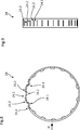
Die
Die
Bei dem in
BezugszeichenlisteLIST OF REFERENCE NUMBERS
- 11
- Getriebeeinheit gear unit
- 22
- Schneckenwelle worm shaft
- 2.1 2.1
- erstes Endefirst end
- 2.2 2.2
- zweites Endesecond end
- 2.3 2.3
- Schneckeslug
- 33
- Schneckenrad worm
- 3.1 3.1
- Zahnkranzsprocket
- 44
- Eingriffsbereich engagement area
- 5, 11, 15, 255, 11, 15, 25
- Kugellager ball-bearing
- 6, 16, 266, 16, 26
- innerer Lagerring inner bearing ring
- 7, 17, 277, 17, 27
- äußerer Lagerring outer bearing ring
- 7.1, 17.1, 27.1 7.1, 17.1, 27.1
- MantelseiteShellside
- 7.2, 7.3, 17.2,17.3, 27.2, 27.37.2, 7.3, 17.2, 17.3, 27.2, 27.3
- Stirnseite front
- 7.4, 7.5, 17.4, 17.5 7.4, 7.5, 17.4, 17.5
- ÜbergangsbereichTransition area
- 9, 10, 19, 209, 10, 19, 20
- gummielastischer Ring rubber-elastic ring
- 1212
- Federanordnung spring assembly
- 13, 21, 2213, 21, 22
- Tellerfeder Belleville spring
- 1414
- Distanzscheibe spacer
- 23, 24 23, 24
- Toleranzringtolerance ring
- 23.1, 24.1 23.1, 24.1
- Vorsprunghead Start
- 24.2 24.2
- Schlitzslot
- 27.4 27.4
- Außenfläche outer surface
- 3030
- Gehäuse casing
- 30.1 30.1
- Innenflächepalm
- 30.2 30.2
- Vorsprunghead Start
- 3131
- Antriebswelle drive shaft
- 3232
- Kupplung clutch
- DD
- Drehachse axis of rotation
- KK
- Kippachse tilt axis
Claims (3)
Priority Applications (4)
| Application Number | Priority Date | Filing Date | Title |
|---|---|---|---|
| DE102016211706.8A DE102016211706B3 (en) | 2016-06-29 | 2016-06-29 | Transmission unit for a motor vehicle |
| DE202016103799.9U DE202016103799U1 (en) | 2016-06-29 | 2016-07-14 | Transmission unit for a motor vehicle |
| CN201710485351.XA CN107542856A (en) | 2016-06-29 | 2017-06-23 | Geared system for motor vehicles |
| US15/634,789 US20180003290A1 (en) | 2016-06-29 | 2017-06-27 | Gear unit for motor vehicle |
Applications Claiming Priority (1)
| Application Number | Priority Date | Filing Date | Title |
|---|---|---|---|
| DE102016211706.8A DE102016211706B3 (en) | 2016-06-29 | 2016-06-29 | Transmission unit for a motor vehicle |
Publications (1)
| Publication Number | Publication Date |
|---|---|
| DE102016211706B3 true DE102016211706B3 (en) | 2017-12-14 |
Family
ID=60419949
Family Applications (1)
| Application Number | Title | Priority Date | Filing Date |
|---|---|---|---|
| DE102016211706.8A Active DE102016211706B3 (en) | 2016-06-29 | 2016-06-29 | Transmission unit for a motor vehicle |
Country Status (3)
| Country | Link |
|---|---|
| US (1) | US20180003290A1 (en) |
| CN (1) | CN107542856A (en) |
| DE (1) | DE102016211706B3 (en) |
Cited By (5)
| Publication number | Priority date | Publication date | Assignee | Title |
|---|---|---|---|---|
| CN107631009A (en) * | 2017-11-07 | 2018-01-26 | 中材建设有限公司 | Adapt to the mesh gear of gear wheel beat |
| CN109268447A (en) * | 2018-11-30 | 2019-01-25 | 江西立德传动设备有限公司 | A kind of compact type worm gear reducer |
| DE102017129429A1 (en) * | 2017-12-11 | 2019-06-13 | Schaeffler Technologies AG & Co. KG | worm gear |
| DE102019120260A1 (en) * | 2019-07-26 | 2021-01-28 | Schaeffler Technologies AG & Co. KG | Gear arrangement with an axial spring means |
| US11873038B2 (en) | 2019-07-10 | 2024-01-16 | Thyssenkrupp Presta Ag | Electromechanical power steering system having a pivot-pendulum bearing assembly |
Families Citing this family (8)
| Publication number | Priority date | Publication date | Assignee | Title |
|---|---|---|---|---|
| DE102018106025A1 (en) * | 2018-03-15 | 2019-09-19 | Thyssenkrupp Ag | Helical gearbox for electromechanical power steering with asymmetrically preloaded fixed bearing |
| DE102018106026A1 (en) | 2018-03-15 | 2019-09-19 | Thyssenkrupp Ag | Worm gear with a swivel bearing with a defined swivel axis |
| CN112384429B (en) * | 2018-07-11 | 2023-02-28 | 蒂森克虏伯普利斯坦股份公司 | Adjusting drive for a steering column, steering column and adjusting method |
| DE102019119705A1 (en) * | 2018-11-26 | 2020-05-28 | Schaeffler Technologies AG & Co. KG | Steering system with swivel bearing |
| CN109340354A (en) * | 2018-12-15 | 2019-02-15 | 阜宁县元丰泵业有限公司 | A kind of large size speed reducer case lid |
| CN111442078B (en) * | 2020-05-07 | 2020-10-02 | 江苏国茂减速机股份有限公司 | Low-noise worm gear speed reducer |
| DE102020129080A1 (en) * | 2020-09-25 | 2022-03-31 | Joyson Safety Systems Germany Gmbh | Steer-by-wire steering system |
| CN113415338B (en) * | 2021-07-12 | 2022-11-04 | 上海汽车工业(集团)总公司 | Steering-by-wire road sensing feedback device |
Citations (11)
| Publication number | Priority date | Publication date | Assignee | Title |
|---|---|---|---|---|
| DE7040270U (en) * | 1971-05-19 | Hurth C Maschinen Und Zahnradfabrik | Toothed drive running with crossed axes | |
| US20070102228A1 (en) * | 2003-04-18 | 2007-05-10 | Koyo Seiko Co., Ltd. | Electric power steering device |
| US7217106B2 (en) * | 2002-12-27 | 2007-05-15 | Mitsubishi Denki Kabushiki Kaisha | Electro-hydraulic power steering apparatus |
| DE102006039740A1 (en) * | 2006-08-24 | 2008-02-28 | Schaeffler Kg | Auxiliary drive, particularly electromechanical auxiliary drive for steering gear, has housing device, spur gear, spiral spindle is held in housing device and engages with spur gear over meshing zone |
| JP2008081060A (en) * | 2006-09-29 | 2008-04-10 | Hitachi Ltd | Power steering device |
| US7490695B2 (en) * | 2002-12-09 | 2009-02-17 | Nsk Ltd. | Electric power steering apparatus |
| DE102009018674A1 (en) * | 2009-04-23 | 2010-10-28 | Schaeffler Technologies Gmbh & Co. Kg | Pivot bearing arrangement for steering gear for pivoted mounting of shaft in housing, has pivot bearing having outer ring and pivot ring, where shaft is arranged in pivoting manner with outer ring opposite to pivot ring |
| US8459402B2 (en) * | 2010-11-09 | 2013-06-11 | Jtekt Corporation | Electric power steering system |
| US20130161114A1 (en) * | 2011-12-26 | 2013-06-27 | Jtekt Corporation | Electric power steering system |
| US9080646B2 (en) * | 2010-03-26 | 2015-07-14 | Robert Bosch Automotive Steering Gmbh | Helical gear mechanism for a steering system of a motor vehicle |
| US20160031473A1 (en) * | 2013-03-06 | 2016-02-04 | Thyssenkrupp Presta Ag | Angularly movable bearing arrangement for pinions in reduction gears of electromechanical steering systems |
Family Cites Families (21)
| Publication number | Priority date | Publication date | Assignee | Title |
|---|---|---|---|---|
| GB191516456A (en) * | 1915-11-22 | 1916-03-09 | William Pickup | Improvements relating to Ball Bearings. |
| US3061386A (en) * | 1961-10-04 | 1962-10-30 | Star Kugelhalter Gmbh Dt | Tolerance rings |
| FR2375572A1 (en) * | 1976-12-23 | 1978-07-21 | Pflieger Roger | Positional adjustment for sighting gear - has worm gear disengaged to permit initial positioning and engaged for fine adjustments |
| US5605071A (en) * | 1995-06-06 | 1997-02-25 | Itt Automotive Electrical Systems, Inc. | Enveloped worm gear clutch wedgelock responsive to reaction force |
| GB2327652B (en) * | 1997-05-29 | 2001-04-18 | Nsk Ltd | Electric power assisted steering apparatus |
| GB9718574D0 (en) * | 1997-09-03 | 1997-11-05 | Lucas Ind Plc | Improvements relating to gears |
| JP3613693B2 (en) * | 1998-07-27 | 2005-01-26 | 光洋精工株式会社 | Electric steering device |
| JP3891747B2 (en) * | 1999-12-07 | 2007-03-14 | 株式会社ジェイテクト | Electric steering device |
| DE10217123A1 (en) * | 2002-04-17 | 2003-12-18 | Bosch Gmbh Robert | Backlash-free steering gear |
| CN100519300C (en) * | 2003-02-20 | 2009-07-29 | 日本精工株式会社 | Electric-powered power steering apparatus |
| DE102004034701A1 (en) * | 2004-07-17 | 2006-02-02 | Zf Lenksysteme Gmbh | Ball bearing has damping rings fitted on inner and outer rings which are held in position against central rib by outer spacers |
| KR100571156B1 (en) * | 2004-10-11 | 2006-04-17 | 엘에스전선 주식회사 | Hybrid bearings |
| JP5017927B2 (en) * | 2006-05-31 | 2012-09-05 | 日本精工株式会社 | Electric power steering device |
| JP5039036B2 (en) * | 2006-07-12 | 2012-10-03 | 日立オートモティブシステムズ株式会社 | Power steering device, reduction mechanism and bearing holder |
| DE102008009107B4 (en) * | 2008-02-14 | 2010-06-17 | Jtekt Europe | Mechanical reduction gear with worm and worm wheel |
| US20090314114A1 (en) * | 2008-06-18 | 2009-12-24 | Elram Engineering And Advanced Technologies 1992 Ltd. | Backlash elimination mechanism for gear systems for low speed applications |
| DE102009053095A1 (en) * | 2009-11-13 | 2011-05-19 | Schaeffler Technologies Gmbh & Co. Kg | Joint bearing for drive shaft of agricultural tractor, has two rows of roller bodies arranged between outer and inner rings, where bodies are designed as casters with surfaces arranged parallel to each other and flattened from base form |
| JP5641195B2 (en) * | 2010-04-13 | 2014-12-17 | 株式会社ジェイテクト | Electric power steering device |
| US8381868B2 (en) * | 2010-08-30 | 2013-02-26 | Jtekt Corporation | Electric power steering system |
| JP6130988B2 (en) * | 2011-03-22 | 2017-05-17 | Kyb株式会社 | Power steering device |
| KR101095978B1 (en) * | 2011-04-08 | 2011-12-19 | 한국델파이주식회사 | Electric power steering apparatus |
-
2016
- 2016-06-29 DE DE102016211706.8A patent/DE102016211706B3/en active Active
-
2017
- 2017-06-23 CN CN201710485351.XA patent/CN107542856A/en active Pending
- 2017-06-27 US US15/634,789 patent/US20180003290A1/en not_active Abandoned
Patent Citations (11)
| Publication number | Priority date | Publication date | Assignee | Title |
|---|---|---|---|---|
| DE7040270U (en) * | 1971-05-19 | Hurth C Maschinen Und Zahnradfabrik | Toothed drive running with crossed axes | |
| US7490695B2 (en) * | 2002-12-09 | 2009-02-17 | Nsk Ltd. | Electric power steering apparatus |
| US7217106B2 (en) * | 2002-12-27 | 2007-05-15 | Mitsubishi Denki Kabushiki Kaisha | Electro-hydraulic power steering apparatus |
| US20070102228A1 (en) * | 2003-04-18 | 2007-05-10 | Koyo Seiko Co., Ltd. | Electric power steering device |
| DE102006039740A1 (en) * | 2006-08-24 | 2008-02-28 | Schaeffler Kg | Auxiliary drive, particularly electromechanical auxiliary drive for steering gear, has housing device, spur gear, spiral spindle is held in housing device and engages with spur gear over meshing zone |
| JP2008081060A (en) * | 2006-09-29 | 2008-04-10 | Hitachi Ltd | Power steering device |
| DE102009018674A1 (en) * | 2009-04-23 | 2010-10-28 | Schaeffler Technologies Gmbh & Co. Kg | Pivot bearing arrangement for steering gear for pivoted mounting of shaft in housing, has pivot bearing having outer ring and pivot ring, where shaft is arranged in pivoting manner with outer ring opposite to pivot ring |
| US9080646B2 (en) * | 2010-03-26 | 2015-07-14 | Robert Bosch Automotive Steering Gmbh | Helical gear mechanism for a steering system of a motor vehicle |
| US8459402B2 (en) * | 2010-11-09 | 2013-06-11 | Jtekt Corporation | Electric power steering system |
| US20130161114A1 (en) * | 2011-12-26 | 2013-06-27 | Jtekt Corporation | Electric power steering system |
| US20160031473A1 (en) * | 2013-03-06 | 2016-02-04 | Thyssenkrupp Presta Ag | Angularly movable bearing arrangement for pinions in reduction gears of electromechanical steering systems |
Cited By (6)
| Publication number | Priority date | Publication date | Assignee | Title |
|---|---|---|---|---|
| CN107631009A (en) * | 2017-11-07 | 2018-01-26 | 中材建设有限公司 | Adapt to the mesh gear of gear wheel beat |
| CN107631009B (en) * | 2017-11-07 | 2022-07-29 | 中材建设有限公司 | Meshing transmission device suitable for large gear deflection |
| DE102017129429A1 (en) * | 2017-12-11 | 2019-06-13 | Schaeffler Technologies AG & Co. KG | worm gear |
| CN109268447A (en) * | 2018-11-30 | 2019-01-25 | 江西立德传动设备有限公司 | A kind of compact type worm gear reducer |
| US11873038B2 (en) | 2019-07-10 | 2024-01-16 | Thyssenkrupp Presta Ag | Electromechanical power steering system having a pivot-pendulum bearing assembly |
| DE102019120260A1 (en) * | 2019-07-26 | 2021-01-28 | Schaeffler Technologies AG & Co. KG | Gear arrangement with an axial spring means |
Also Published As
| Publication number | Publication date |
|---|---|
| CN107542856A (en) | 2018-01-05 |
| US20180003290A1 (en) | 2018-01-04 |
Similar Documents
| Publication | Publication Date | Title |
|---|---|---|
| DE102016211706B3 (en) | Transmission unit for a motor vehicle | |
| DE102016211694B3 (en) | Transmission unit for a motor vehicle | |
| DE102016211714B3 (en) | Transmission unit for a motor vehicle | |
| EP3573874B1 (en) | Motor-adjustable steering column for a motor vehicle and adjustment drive for a steering column | |
| DE102013003749A1 (en) | Angularly movable bearing arrangement for pinions in reduction gears of electromechanical steering systems | |
| DE102011003485B4 (en) | Ball screw and thus equipped steering device | |
| EP3820762B1 (en) | Adjustment drive for a steering column, a steering column with a motor driven lenght adjustment device for a vehicle and method for adjusting a bearing arrangement of an adjustment drive | |
| DE202016103799U1 (en) | Transmission unit for a motor vehicle | |
| EP2345569B1 (en) | Screw gearing for the steering of a motor vehicle | |
| DE202017100155U1 (en) | Transmission unit for a motor vehicle | |
| EP3880980B1 (en) | Adjustment drive for a steering column and steering column for a motor vehicle | |
| WO2014009270A1 (en) | Adjustment drive | |
| DE202018104386U1 (en) | Adjustment drive for a steering column, motor-adjustable steering column for a motor vehicle, and apparatus for performing a method for adjusting a bearing assembly of an adjustment | |
| WO2020074385A1 (en) | Plain bearing for a coupling rod of a steer-by-wire steering gear | |
| DE102009018674A1 (en) | Pivot bearing arrangement for steering gear for pivoted mounting of shaft in housing, has pivot bearing having outer ring and pivot ring, where shaft is arranged in pivoting manner with outer ring opposite to pivot ring | |
| DE102017200008B4 (en) | Transmission unit for a motor vehicle | |
| DE102016211681B3 (en) | Transmission unit for a motor vehicle | |
| DE102016211715A1 (en) | Transmission unit for a motor vehicle | |
| DE202016103794U1 (en) | Transmission unit for a motor vehicle | |
| DE102012103857A1 (en) | Apparatus for pressing worm/screw pinion to worm/screw gear for steering system of motor vehicle, has thrust element to limit movement of worm/screw pinion away from worm/screw gear during backlash | |
| DE102009016187B4 (en) | Bearing for a device for generating a pivoting moment | |
| DE202016103802U1 (en) | Transmission unit for a motor vehicle | |
| DE102016211707A1 (en) | Transmission unit for a motor vehicle | |
| DE102018208200A1 (en) | Actuator with a spindle drive and steer-by-wire steering | |
| DE102016121393A1 (en) | Ball bearing and method for its manufacture, fixed bearing, steering gear and steering system |
Legal Events
| Date | Code | Title | Description |
|---|---|---|---|
| R012 | Request for examination validly filed | ||
| R016 | Response to examination communication | ||
| R016 | Response to examination communication | ||
| R018 | Grant decision by examination section/examining division | ||
| R020 | Patent grant now final | ||
| R082 | Change of representative |
Representative=s name: MARKOWITZ, MARKUS, DR.-ING., DE |