EP1570995A1 - Tintenpatronen und Verfahren zum Füllen von Tintenpatronen - Google Patents
Tintenpatronen und Verfahren zum Füllen von Tintenpatronen Download PDFInfo
- Publication number
- EP1570995A1 EP1570995A1 EP05004679A EP05004679A EP1570995A1 EP 1570995 A1 EP1570995 A1 EP 1570995A1 EP 05004679 A EP05004679 A EP 05004679A EP 05004679 A EP05004679 A EP 05004679A EP 1570995 A1 EP1570995 A1 EP 1570995A1
- Authority
- EP
- European Patent Office
- Prior art keywords
- ink
- opening
- region
- sealing member
- cartridge
- Prior art date
- Legal status (The legal status is an assumption and is not a legal conclusion. Google has not performed a legal analysis and makes no representation as to the accuracy of the status listed.)
- Withdrawn
Links
- 238000000034 method Methods 0.000 title claims abstract description 66
- 238000007789 sealing Methods 0.000 claims abstract description 80
- 238000004891 communication Methods 0.000 claims description 46
- 239000000463 material Substances 0.000 claims description 5
- 239000000976 ink Substances 0.000 description 518
- 238000002347 injection Methods 0.000 description 56
- 239000007924 injection Substances 0.000 description 56
- 238000009423 ventilation Methods 0.000 description 18
- 238000005192 partition Methods 0.000 description 15
- 230000002093 peripheral effect Effects 0.000 description 11
- 230000007246 mechanism Effects 0.000 description 9
- 238000000605 extraction Methods 0.000 description 8
- 230000004048 modification Effects 0.000 description 6
- 238000012986 modification Methods 0.000 description 6
- 238000010926 purge Methods 0.000 description 5
- 229920003051 synthetic elastomer Polymers 0.000 description 5
- 239000005061 synthetic rubber Substances 0.000 description 5
- 239000010409 thin film Substances 0.000 description 5
- 238000003780 insertion Methods 0.000 description 4
- 230000037431 insertion Effects 0.000 description 4
- 230000015572 biosynthetic process Effects 0.000 description 3
- 239000003086 colorant Substances 0.000 description 3
- 230000006835 compression Effects 0.000 description 2
- 238000007906 compression Methods 0.000 description 2
- 238000010276 construction Methods 0.000 description 2
- 238000005553 drilling Methods 0.000 description 2
- 230000005484 gravity Effects 0.000 description 2
- 239000012535 impurity Substances 0.000 description 2
- 238000007639 printing Methods 0.000 description 2
- 229920003002 synthetic resin Polymers 0.000 description 2
- 239000000057 synthetic resin Substances 0.000 description 2
- 230000009471 action Effects 0.000 description 1
- 230000002411 adverse Effects 0.000 description 1
- 230000006837 decompression Effects 0.000 description 1
- 230000003247 decreasing effect Effects 0.000 description 1
- 238000001514 detection method Methods 0.000 description 1
- 238000011161 development Methods 0.000 description 1
- 230000018109 developmental process Effects 0.000 description 1
- 238000001704 evaporation Methods 0.000 description 1
- 230000008020 evaporation Effects 0.000 description 1
- 230000005499 meniscus Effects 0.000 description 1
- 230000003287 optical effect Effects 0.000 description 1
- 230000035699 permeability Effects 0.000 description 1
- 230000008569 process Effects 0.000 description 1
- 230000009467 reduction Effects 0.000 description 1
- 238000003466 welding Methods 0.000 description 1
Images


Classifications
-
- B—PERFORMING OPERATIONS; TRANSPORTING
- B41—PRINTING; LINING MACHINES; TYPEWRITERS; STAMPS
- B41J—TYPEWRITERS; SELECTIVE PRINTING MECHANISMS, i.e. MECHANISMS PRINTING OTHERWISE THAN FROM A FORME; CORRECTION OF TYPOGRAPHICAL ERRORS
- B41J2/00—Typewriters or selective printing mechanisms characterised by the printing or marking process for which they are designed
- B41J2/005—Typewriters or selective printing mechanisms characterised by the printing or marking process for which they are designed characterised by bringing liquid or particles selectively into contact with a printing material
- B41J2/01—Ink jet
- B41J2/17—Ink jet characterised by ink handling
- B41J2/175—Ink supply systems ; Circuit parts therefor
- B41J2/17503—Ink cartridges
- B41J2/17506—Refilling of the cartridge
Definitions
- the invention relates to ink cartridges and methods of filling ink cartridges.
- Inkjet printers that perform printing by ejecting ink from nozzles toward a recording sheet may be provided with ink cartridges. Such ink cartridges are generally replaced and disposed of after the ink contained therein has been consumed. By using ink cartridges, ink can be easily replenished in the inkjet printer. However, spent ink cartridges are disposed of every time ink contained therein has been consumed, which may lead to increased operating costs. Thus, JP 3453562 discloses a technique including drilling a hole in a wall of an ink cartridge in which ink has been consumed and refilling the ink cartridge through the hole.
- JP 3453562 a hole is drilled in a side wall of an ink cartridge, ink is introduced into the ink cartridge through the hole, and then the hole is sealed when filling is complete.
- ink may leak from the hole during operation. As such processes must be performed with considerable care, they may be troublesome for users.
- Ink cartridges may be formed with ink chambers into which ink is introduced from outside using an ink syringe.
- JP-A-2003-305865 discloses attaching a synthetic rubber plug member to an ink fill portion where an ink fill hole is formed.
- an injection needle of an ink syringe is inserted through the plug member, and ink is introduced into the ink cartridge via the injection needle.
- the hole formed in the plug member when the needle is inserted may not be closed perfectly by the elasticity of the plug member, depending on how the needle is inserted. In such cases, ink may leak from the hole or air and impurities may be introduced to the cartridge through the hole. Also, if it is necessary to insert an additional needle into the ink cartridge during filling, for example for deaeration, the filling needle and the additional needle may be inserted into similar positions on the plug member producing a comparatively large hole. It may be difficult to seal such a large hole relying only on the elasticity of the plug member.
- the disclosure provides an ink cartridge capable of sealing a hole to be formed in a plug member when a needle is inserted into the plug member for ink filling with reliability, and a method of filling ink cartridges that can be performed with facility.
- the object is solved by a method according to claim 1.
- the ink tank can be easily filled.
- ink can be repeatedly supplied in the ink tank, thereby allowing reuse of the cartridge and reducing the operating costs.
- the ink supply tube is a syringe needle and the sealing member is formed of a material having an elasticity such that a hole formed by the syringe needle will tend to close itself when the syringe needle is removed.
- the hole can be closed by elastic force inherent in the sealing member with reliability.
- the method further includes moving the sealing member from the first region to a second region in the ink inflow passage adjacent to the second opening before inserting the ink supply tube.
- the sealing member can make intimate contact with the first opening of the ink inflow passage that communicates with the ink tank.
- ink can be easily introduced.
- the method further includes removing the ink supply tube from the ink inflow passage, and moving the sealing member from the second region to the first region. It is preferable that moving the sealing member from the second region to the first region includes moving the sealing member into a position such that a surface of the sealing member seals the first opening, the surface being a surface that has not been penetrated by the ink supply tube.
- the method may include: inserting an air communication tube through the sealing member and into a first region in the ink inflow passage adjacent to the first opening.
- the method further includes moving the sealing member from the first region to a second region in the ink inflow passage adjacent to the second opening before inserting the air communication tube and the ink supply tube.
- the sealing member can make intimate contact with the first opening of the ink inflow passage that communicates with the ink tank.
- ink can be easily introduced.
- the method further includes removing the air communication tube and the ink supply tube from the ink inflow passage, and moving the sealing member from the second region to the first region. It is preferable that moving the sealing member from the second region to the first region includes moving the sealing member into a position such that a surface of the sealing member seals the first opening, the surface being a surface that has not been penetrated by the air communication tube or the ink supply tube.
- the air communication tube and the ink supply tube are a syringe needles and the sealing member is formed of a material having an elasticity such that holes formed by the syringe needles will tend to close themselves when the syringe needles are removed.
- the hole can be closed by elastic force inherent in the sealing member with reliability.
- the object is also attained by a method according to claim 13.
- the ink tank can be easily filled.
- ink can be repeatedly supplied in the ink tank, thereby allowing reuse of the cartridge and reducing the operating costs.
- the first region has a truncated conical shape and moving the sealing member from the second region to the first region includes moving the sealing member into the first region so that it contacts an end surface of the ink inflow passage opposite from the second opening.
- the sealing member when the sealing member is in contact with the end surface in the first region, the first opening can be sealed with the sealing member with reliability.
- a sealing member having elasticity is force-fitted into the ink inflow passage.
- ink is introduced into the ink tank via the injection needle.
- the sealing member is force-fitted into the ink inflow passage until it is located in the first region, thereby increasing a compression force acting on the sealing member from the ink inflow passage.
- a through hole formed through the sealing member on insertion of the injection needle can be closed with reliability.
- the ink cartridges further include a stepped portion between the first region and the second region.
- the sealing member is force-fitted into the ink inflow passage until it is located to the portion nearer the ink tank from the stepped portion, thereby increasing a compression force acting on the elastic member from the ink inflow passage.
- a through hole formed through the elastic member on insertion of the injection needle can be closed with reliability.
- a first angle between the first region and the stepped portion and a second angle between the second region and the stepped portion are obtuse.
- the second opening is partitioned into multiple openings.
- the needles can be inserted from respective partitioned entrances, thereby preventing formation of a large through hole. Further, the sealing member can be prevented from coming off from the ink inflow passage.
- the ink inflow passage includes a side wall and an end surface, the first region is provided in a truncated conical shape, and the first opening is provided on the side wall at a location adjacent to the end surface.
- the first opening can be sealed with the sealing member with reliability. Further, because the first opening is provided on the side wall at the location adjacent to the end surface, a through hole, which is formed when a needle is inserted into the sealing member, and the first opening are spaced away from each other in plan view of the sealing member. Thus, when the sealing member is force-fitted into the end surface of the ink inflow passage, the first opening can be securely sealed by the sealing member regardless of the size of the through hole.
- the inkjet printer 1 includes an inkjet head 2 having nozzles 2a that eject ink of four colors, cyan (C), yellow (Y), magenta (M), and black (K) onto a recording sheet P; four holders 4 (4a, 4b, 4c, and 4d) in which four ink cartridges 3 (3a, 3b, 3c, 3d) containing ink of one of the four colors respectively are installed; a carriage moving mechanism 5 that reciprocates the inkjet head 2 linearly in a direction along guides 9 (in a direction perpendicular to the drawing sheet); a conveying mechanism 6 that conveys the recording sheet P in a direction perpendicular to the moving direction of the inkjet head 2 and parallel to an ink ejection surface of the inkjet head 2; and a purge device
- the inkjet head 2 is reciprocated by the carriage moving mechanism 5 in a direction perpendicular to the drawing sheet of FIG. 1, while the recording sheet P is conveyed by the conveying mechanism 6 in a left-right direction on the page in FIG. 1.
- ink is supplied from the ink cartridges 3 installed in the holders 4 via a supply tube 10 to the nozzles 2a of the inkjet head 2, and ink is ejected from the nozzles 2a toward the recording sheet P, so that printing is performed on the recording sheet P.
- the purge device 7 includes a purge cap 11 and a suction pump 7a.
- the purge cap 11 is movable in directions toward or away from the ink ejection surface and is detachably attachable to the inkjet head 2 so as to cover the ink ejection surface.
- the suction pump 7a suctions ink and/or air from the nozzles 2a.
- the purge device 7 is capable of suctioning air bubbles or ink having a high viscosity as a result of evaporation of volatile elements, trapped in the inkjet head 2 from the nozzles 2a by the action of the suction pump 7a.
- the four holders 4a to 4d are arranged in a line and attached to the corresponding ink cartridges 3a to 3d each storing one of cyan, yellow, magenta, and black inks, respectively.
- an ink extraction tube 12 and an air introducing tube 13 are disposed so as to correspond to an ink supply valve 21 and an air communication valve 22 in the ink cartridge 3.
- the holder 4 is also provided with an optical sensor 14 for detecting a remaining amount of ink (ink level) in the ink cartridge 3.
- the sensor 14 has a light emitting portion 14a and a light receiving portion 14b that are positioned at the same height in a face-to-face relationship with each other so as to sandwich at least a portion of the ink cartridge 3 therebetween.
- the sensor 14 detects whether light from the light emitting portion 14a is interrupted by a shutter mechanism 23 provided in the ink cartridge 3, and outputs the detection result to a control device (not shown) that governs operation of the inkjet printer 1.
- the ink cartridge 3 will be further described with reference to FIGS. 2-7.
- the ink cartridges 3a-3d are identical in shape, structure and operation with each other, except that each contains a different color of ink, the following description will be made with respect to one ink cartridge.
- the ink cartridge 3 is provided with a cartridge body 20, the ink supply valve (ink valve) 21, the air communication valve (air valve) 22, a shutter mechanism 23, and a cap 24.
- the cartridge body 20 contains ink therein.
- the ink supply valve (ink valve) 21 is capable of opening and closing an ink supply passage through which ink in the cartridge body 20 is supplied to the ink jet head 2.
- the air communication valve 22 is capable of opening and closing an air introducing passage through which air can be transmitted to the cartridge body 20 from outside of the cartridge 3.
- the shutter mechanism 23 obstructs light emitted by the light emitting portion 14a of the sensor 14 to detect an ink level.
- the cap 24 covers a lower end portion of the cartridge body 20.
- the cartridge body 20 may be made of a synthetic resin having light permeability.
- a partition wall 30 that extends horizontally is integrally formed with the cartridge body 20.
- the partition wall 30 divides an internal space of the cartridge body 20 into an ink chamber (ink tank) 31, which is situated above the partition wall 30, and two valve chambers 32 and 33, which are situated below the partition wall 30.
- Ink is stored in the ink chamber 31.
- the ink supply valve 21 and the air communication valve 22 are accommodated in the valve chambers 32, 33, respectively.
- a protruding portion 34 which protrudes outwardly, is formed at a substantially central portion of a side of the cartridge body 20 with respect to its height.
- a light-shielding plate 60 of a shutter mechanism 23 is disposed in a space defined by the protruding portion 34.
- the protruding portion 34 With the ink cartridge 3 attached to the holder 4, the protruding portion 34 is sandwiched between the light emitting portion 14a and the light-receiving portion 14b of the sensor 14.
- a lid member 35 is welded at an upper end portion of the cartridge body 20, to enclose the ink chamber 31 in the cartridge body 20.
- an ink fill hole (ink inflow passage) 36 for introducing ink to the ink chamber 31 of the ink cartridge 3 is formed between the two valve chambers 32, 33.
- the ink fill hole 36 communicates with the ink chamber 31 in the cartridge body 20 via an upper opening 36a and communicates with the outside via a lower opening 36b.
- a sealing or plug member 37 such as an elastic (e.g., synthetic rubber) plug member, is force-fitted into an upper end of the ink fill hole 36.
- the plug member 37 is cylindrical and seals the opening 36a at its peripheral side surface.
- a tubular portion 38 which protrudes downward, is integrally formed with a portion of the partition wall 30 that forms a top portion of the valve chamber 32 where the ink supply valve 21 is accommodated.
- the tubular portion 38 is provided, at its lower end, with a thin film portion 39 that closes a passage formed in the tubular portion 38.
- Tubular portions 40, 41 which protrude upward and downward, respectively, are integrally formed with the partition wall 30 that forms a top portion of the valve chamber 33 where the air communication valve 22 is accommodated.
- the lower tubular portion 41 is provided with a thin film portion 42 that closes passages formed in the tubular portions 40, 41 at a lower end.
- the tubular portion 40 is provided, at its upper end, with a tubular member 43 that extends to the upper end of the ink chamber 31.
- the ink supply valve 21 includes a valve housing 45 and a valve body 46.
- the valve housing 45 may be made of a synthetic rubber, and is formed in a substantially tubular shape and has elasticity.
- the valve body 46 may be made of a synthetic resin and is accommodated in the valve housing 45.
- the valve housing 45 includes an urging member 47, a valve seat 48, and an engaging portion 49, which are arranged in this order from the upper end (the ink chamber 31 side) and formed integrally.
- a bottom surface of the valve body 46 makes contact with a top surface of the valve seat 48 (an end surface facing the ink chamber 31).
- a through hole 48a extending vertically is formed substantially in a central axis of the valve seat 48.
- the engaging portion 49 has a guide hole 49a that communicates with the through hole 48a and extends downwardly.
- the guide hole 49a is shaped such that its diameter becomes greater toward the bottom end.
- a circular groove 49b is formed around the guide hole 49a. The groove 49b allows a wall portion forming the guide hole 49a to deform elastically and easily toward a direction that the diameter of the guide hole 49a becomes greater.
- the ink extraction tube 12 when the ink extraction tube 12 is inserted into the guide hole 49a, a sealing fit between the guide hole 49a and the ink extraction tube 12 is improved thereby preventing ink leakage as much as possible. Even if the ink extraction tube 12 is inserted into the guide hole 49a on a slant or is not completely inserted into the guide hole 49a, the ink extraction tube 12 can be inserted into the guide hole 49a with reliability because the wall portion forming the guide hole 49a deforms in a direction that causes the diameter of the guide hole 49a to become greater.
- the urging member 47 has a side wall portion 47a and an overhang 47b.
- the side wall portion 47a extends from the outer surface of the valve seat 48 upwardly toward the ink chamber 31.
- the overhang 47b is integral with the side wall portion 47a and extends radially inward from the upper end of the side wall portion 47a.
- the bottom surface of the overhang 47b makes contact with the valve body 46, and the valve body 46 is urged downward by elastic force of the side wall portion 47a and the overhang 47b.
- an opening 47c is formed inside the overhang 47b, so that the side wall portion 47a and the overhang 47b, which are integrally formed, are easily deformed.
- the valve body 46 has a bottom portion 50, a valve side wall portion 51, and a breaking portion 52.
- the bottom portion 50 makes contact with the valve seat 48.
- the valve side wall portion 51 is formed in a tubular shape and extends from the valve side wall portion 51 upward toward the ink chamber 31.
- the breaking portion 52 projects from a center of the bottom portion 50 toward the ink chamber 31 higher than the valve side wall portion 51.
- An annular protrusion 50a that protrudes toward the valve seat 48 is formed at the bottom surface of the bottom portion 50 (which is an end surface facing the valve seat 48).
- the through hole 48a of the valve seat 48 is closed by the valve body, and thus the ink supply passage is closed.
- a plurality of passages (e.g. eight passages in this embodiment) 53 are formed at equal intervals in the bottom portion 50 in between the outside of the annular protrusion 50a and the inside of the valve side wall portion 51. The passages 53 provide communication between the upper space above the valve body 46 and the lower space below the valve body 46.
- the breaking portion 52 is made up of four plate-like members 52a, 52b, 52c, 52d that are assembled in the shape of a cross in a plan view, and is held upright relative to a substantially central portion of the bottom portion 50. Grooves 54 that extend vertically are formed between the four plate-like members 52a to 52d. The breaking portion 52 protrudes upwardly through the opening 47c inside of the overhang 47b such that its end is disposed at a place slightly lower than the thin film portion 39 as shown in FIG. 4.
- the ink extraction tube 12 is inserted into the guide hole 49a.
- the valve body 46 is pressed up by the tip of the ink extraction tube 12 against the urging force of the urging member 47.
- the valve body 46 moves upward while deforming the urging member 47, and the annular protrusion 50a is separated from the valve seat 48.
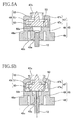
- the thin film portion 39 is broken by the end of the breaking portion 52 of the valve body 46 moving upward, so that ink in the ink chamber 31 flows into the valve chamber 32 via the passage in the tubular portion 38, as shown in FIGS. 4 and 5B.
- ink is supplied from the ink extraction tube 12 to the inkjet printer 1 via the passages 53 of the valve body 46.
- the air communication valve 22 also includes the valve housing 45 and the valve body 46 accommodated in the valve housing 45. That is, the air communication valve 22 is also structured so that the valve body 46 is urged downward by the urging member 47 and brought into intimate contact with the valve seat 48 of the valve housing 45 so as to close the through hole 48a.
- the air introducing tube 13 is inserted into the guide hole 49a formed in the valve housing 45, the valve body 46 moves up and the thin film portion 42 of the tubular portion 41 is broken by the breaking portion 52. Subsequently, air flows into the valve chamber 33 from the air introducing tube 13 via the passages 53 of the valve body 46, and air is guided to an upper part of the ink chamber 31.
- the shutter mechanism 23 is disposed in a lower portion of the ink chamber 31, and includes the light-shielding plate 60, a hollow float 61, a connecting member 62 that connects the light-shielding plate 60 and the float 61, and a support stand 63 that pivotally supports the connecting member 62 disposed above the partition wall 30.
- the light-shielding plate 60 and the float 61 are provided at both ends of the connecting member 62.
- the connecting member 62 is disposed within a vertical plane parallel to the sheet of FIG. 4 so as to pivot on a central point of the support stand 63.
- the light-shielding plate 60 is a thin plate in parallel with the vertical plane and having a specified area. With the ink cartridge 3 attached to the holder 4, the light emitting portion 14a and the light receiving portion 14b reach a height equal to the protruding portion 34 formed at a side wall portion of the cartridge body 20. When the light-shielding plate 60 is positioned in a space defined by the protruding portion 34, the light-shielding plate 60 prevents light emitted by the light emitting portion 14a of the sensor 14 from passing through a transparent wall portion of the cartridge body 20 and ink in the ink chamber 31.
- the float 61 is a cylindrical member filled with air, and its specific gravity is smaller than the specific gravity of ink in the ink chamber 31.
- the float 61 floats toward the surface of the ink and the light-shielding plate 60, which is provided at the other end of the connecting member 62, is located at a position in the protruding portion 34 (a position indicated by a solid line in FIG. 4) such that light emitted by the light emitting portion 14a is prevented from passing through the protruding portion 34.
- the ink level is decreased and a part of the float 61 starts to rise to the surface of the ink, buoyancy will cause the float 61 to descend with the ink level.
- the light-shielding plate 60 moves to a position higher than the protruding portion 34 (a position indicated by a chain line in FIG. 4) so that the light-shielding plate 60 does not prevent light emitted by the light emitting portion 14a from passing through the protruding portion 34.
- a position indicated by a chain line in FIG. 4 unobstructed by the light-shielding plate 60, light emitted by the light emitting portion 14a passes through the protruding portion 34 and ink in the ink chamber 31, and is received by the light receiving portion 14b. In this way, the low ink level is detected by the sensor 14.
- the cap 24 is fixed to the cartridge body 20, for example, by ultrasonic welding to cover the lower end portion of the cartridge body 20.
- two annular protrusions 65 that protrude downwardly are formed at positions corresponding to the ink supply valve 21 and the air communication valve 22.
- FIGS. 7 to 11 An exemplary method of filling an ink cartridge 3 where ink has been used up and the ink chamber 31 has become empty will be described with reference to FIGS. 7 to 11.
- the ink cartridge 3 in which the ink chamber 31 has become empty is removed from the holder 4.
- the ink cartridge 3 is positioned so that an opening of the tubular member 43 that communicates with the ink chamber 31 faces up.
- an air ventilation tube 77 is inserted into the guide hole 49a of the air communication valve 22 in a direction of an arrow 101, so that the air communication valve 22 is opened.
- the plug member 37 disposed so as to seal the opening 36a of the ink fill hole 36 is separated away from the opening 36a in the direction of the arrow 102 and disposed near the opening 36b.
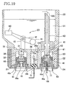
- an injection needle (ink supply tube) 75 of an ink syringe (not shown) is inserted into the plug member 37 in a direction of an arrow 103 such that the injection needle 75 passes through and is exposed from the top surface of the plug member 37.
- the injection needle 75 should be inserted until an ink outlet 75a formed near the tip of the injection needle 75 is positioned completely through the plug member 37 and toward the ink chamber 31. That is, the ink outlet 75a should be located nearer the ink chamber 31 than the plug member 37 is. Then the ink syringe is operated so that ink is introduced into the cartridge body 20. As shown in FIG.
- the introduced ink passes through the inside of the injection needle 75 past the plug member 37 and is discharged into the ink fill hole 36 from the ink cutlet 75a.
- the introduced ink flows in the ink chamber 31 through the opening 36a of the ink fill hole 36 (in a direction of an arrow 104).
- air in the ink chamber 31 corresponding to an amount of the introduced ink is discharged from the ink chamber 31 through the air communication valve 22 and the air ventilation tube 77.
- the amount of the introduced ink is preferably an amount sufficient to cause the ink to reach a level near the opening of the tubular member 43 in the ink chamber 31, but not higher than the opening of the tubular member 43 (even if the ink level rises when the cartridge is resealed).
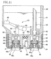
- the injection needle 75 is pulled out from the plug member 37.
- a through hole which is formed in the plug member 37 after the injection needle 75 is inserted, is closed by elastic force inherent in the plug member 37.
- the plug member 37 disposed near the opening 36b is moved up to the upper end of the ink fill hole 36 in a direction of an arrow 106 so as to seal the opening 36a at its peripheral side surface.
- the air ventilation tube 77 is pulled out from the guide hole 49a of the air communication valve 22, the air communication valve 22 is closed, and the filling is complete.
- the ink chamber 31 can be easily filled with ink without modifying to the cartridge body 20.
- ink can be repeatedly supplied in the cartridge body 20, thereby allowing reuse of the cartridge body 20 and reducing the operating costs.
- the plug member 37 is separated from the opening 36a, so that ink can be easily filled through the ink fill hole 36 at a location nearer to the ink chamber 31 than the plug member 37.
- the plug member 37 seals the opening 36a at its peripheral side surface and the injection needle 75 of the ink syringe is exposed from the top surface of the plug member 37.
- Removal of the air ventilation tube 77 is carried out after sealing with the plug member 37 is performed. Accordingly, a pressure increase associated with resealing does not occur, and a condition that might adversely affect ink meniscus formation at nozzles 2a does not occur. Accordingly, a stable ink supply is protected.
- FIGS. 12-14 depict a method of filling with respect to an ink cartridge 3, which has a configuration similar or the same as the ink cartridge 3 shown in FIGS. 7-11. Accordingly, like reference numerals are used and description of like features is omitted in the interest of brevity.
- the ink cartridge 3 in which the ink chamber 31 has become empty is removed from the holder 4.
- the ink cartridge 3 is placed with an opening of the tubular member 43 that communicates with the ink chamber 31 face up.
- One end of a pump tube 91a which is connected to a pump 91 at the other end, is inserted into the guide hole 49a of the air communication valve 22 in a direction of an arrow 201, so that the air communication valve 22 is opened.
- the plug member 37 disposed so as to seal the opening 36a of the ink fill hole 36, is separated away from the opening 36a in the direction of the arrow 202 and is disposed near the opening 36b.
- air in the ink chamber 31 is suctioned until pressure is reduced to a specified value.
- the pump tube 91 a is pulled out from the guide hole 49a.
- an injection needle 75 connected to an ink tank for ink filling (not shown) is inserted into the plug member 37 in a direction of an arrow 203 such that the injection needle 75 passes through and is exposed from the top surface of the plug member 37.
- the injection needle 75 should be inserted until an ink outlet 75a formed near the tip of the injection needle 75 is located at a position completely through the plug member 37 and toward the ink chamber 31.
- ink in the ink tank for filling passes through the inside of the injection needle 75, through the plug member 37 and is discharged in the ink fill hole 36 from the ink outlet 75a.
- the introduced ink flows into the ink chamber 31 through the opening 36a of the ink fill hole 36 (in a direction of an arrow 204).
- pressure in the ink chamber reaches a specified value and ink filling is stopped.
- ink filling is stopped while the ink chamber 31 is kept under a negative pressure.
- the injection needle 75 is pulled out from the plug member 37.
- a through hole which is formed in the plug member 37 after the injection needle 75 is inserted, is closed by the elastic force of the plug member 37.
- the plug member 37 disposed near the opening 36b is moved up to the upper end of the ink fill hole 36 in a direction of an arrow 106 so as to seal the opening 36a at its peripheral side surface. This completes ink filling.
- the ink chamber 31 can be easily filled without modification to the cartridge body 20.
- ink filling is stopped while the ink chamber 31 is kept under a negative pressure. Accordingly, air present in ink can be controlled, and ink ejection properties of the ink can be maintained stably for long periods.
- FIGS. 15-19 depict a method of filling with respect to an ink cartridge 3, which has a configuration similar or the same as the ink cartridge 3 shown in FIGS. 7-14. Accordingly, like reference numerals are used and description of like features is omitted in the interest of brevity.
- the ink cartridge 3 in which the ink chamber 31 has become empty is removed from the holder 4.
- the removed ink cartridge 3 is placed with the valve chamber 32 positioned up.
- the air ventilation tube 77 is inserted into the guide hole 49a of the ink supply valve 21 in a direction of an arrow 301, so that the ink supply valve 21 is open.
- the plug member 37 disposed so as to seal the opening 36a of the ink fill hole 36 is separated away from the opening 36a in a direction of an arrow 302 and is disposed near the opening 36b.
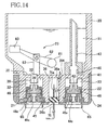
- the injection needle 75 of an ink syringe (not shown) is inserted into the plug member 37 in a direction of an arrow 303 such that the injection needle 75 passes through the plug member 37.
- the injection needle 75 should be inserted until the ink outlet 75a formed near the tip of the injection needle 75 is located toward the ink chamber 31 completely through the plug member 37. That is, the ink outlet 75a should be located nearer the ink chamber 31 than the plug member 37 is.
- the ink syringe is operated such that ink is introduced into the ink chamber 31.
- the introduced ink passes through the inside of the injection needle 75, through the plug member 37 and is discharged in the ink fill hole 36 from the ink outlet 75a.
- the introduced ink flows in the ink chamber 31 from the opening 36a of the ink fill hole 36 (in a direction of an arrow 304). At this time, as shown by an arrow 305, air in the ink chamber 31 is discharged outside through the ink supply valve 21 in accordance with an amount of the introduced ink.
- the ink filling by the ink syringe is stopped.
- the injection needle 75 is pulled out from the plug member 37.
- a through hole which is formed in the plug member 37 after the injection needle 75 is inserted, is closed by itself due to elastic force exerted by the plug member 37.
- the plug member 37 disposed near the opening 36b is moved down to the lower end of the ink fill hole 36 in a direction of an arrow 306 so as to seal the opening 36a at its peripheral side surface.
- the air ventilation tube 77 is pulled out from the guide hole 49a of the ink supply valve 21, the ink supply valve 21 is closed, and the ink filling is completed.
- the ink chamber 31 can be easily filled without modification to the cartridge body 20. Ink is introduced in accordance with the amount of air discharged outside through the air ventilation tube 77. Thereby, substantially the entire of the volume of the ink chamber 31 can be filled with ink, so that ink filling efficiency is high.
- FIGS. 20 and 21 depict a method of filling with respect to an ink cartridge 3, which has a configuration similar or the same as the ink cartridge 3 shown in FIGS. 7-19. Accordingly, like reference numerals are used and description of like features is omitted in the interest of brevity.
- the ink cartridge 3 in which the ink chamber 31 has become empty is removed from the holder 4.
- the removed ink cartridge 3 is placed with the opening 36a of the ink fill hole 36 positioned up.
- the plug member 37 positioned so as to seal the opening 36a of the ink fill hole 36 is separated away from the opening 36a in a direction of an arrow 402 and disposed near the opening 36b.
- a ventilation needle (air communication tube) 76 for communication with air is inserted into the plug member 37 in a direction of an arrow 401 such that the ventilation needle 76 passes through the bottom surface of the plug member 37.
- the ventilation needle 76 should be inserted until a communication hole 76a formed near the tip of the ventilation needle 76 is located completely through the plug member 37 toward the ink chamber 31. That is, the communication hole 76a should be located nearer the ink chamber 31 than the plug member 37 is.
- the injection needle 75 of an ink syringe (not shown) is inserted into the plug member 37 such that the injection needle 75 passes through the bottom surface of the plug member 37 (in a direction of an arrow 403).
- the injection needle 75 should be inserted until the ink outlet 75a formed near the tip of the injection needle 75 is located completely through the plug member 37 toward the ink chamber 31. That is, the ink outlet 75a should be located nearer the ink chamber 31 than the plug member 37 is. Then the ink syringe is operated such that ink is introduced into the cartridge body 20. As shown in FIG. 21, the introduced ink passes through the inside of the injection needle 75, through the plug member 37 and is introduced in the ink fill hole 36 from the ink outlet 75a. Further, the thus introduced ink flows in the ink chamber 31 from the opening 36a of the ink fill hole 36 (in a direction of an arrow 404).
- the ventilation needle 76 and the injection needle 75 are pulled out from the plug member 37.
- through holes, which are formed in the plug member 37 after the ventilation needle 76 and the injection needle 75 are inserted, are closed by elastic force exerted by the plug member 37.
- the plug member 37 disposed near the opening 36b is moved down to the lower end of the ink fill hole 36 so as to seal the opening 36a at its peripheral side surface. This completes ink filling.
- the ink chamber 31 can be easily filled with ink without modification of the cartridge body 20. It is preferable that, during ink filling, the communication hole 76a is disposed near the plug member 37 and the ink outlet 75a is disposed near the opening 36a. With this arrangement, the amount of ink to be introduced into the ink chamber 31 can be increased.
- FIG. 22 depicts a method of filling with respect to an ink cartridge 3, which has a configuration similar or the same as the ink cartridge 3 shown in FIGS. 7-21. Accordingly, like reference numerals are used and description of like features is omitted in the interest of brevity.
- the ink cartridge 3 in which the ink chamber 31 has become empty is removed from the holder 4.
- the removed ink cartridge 3 is placed with the opening 36a of the ink fill hole 36 face up.
- the plug member 37 disposed so as to seal the opening 36a of the ink fill hole 36 is removed.
- Ink stored in an ink tank 92 for ink filling is directly introduced into the ink fill hole 36 from the opening 36b.
- the introduced ink drips off into the ink chamber 31 via the opening 36a of the ink fill hole 36.
- the plug member 37 is positioned at the lower end of the ink fill hole 36 so as to seal the opening 36a. This completes ink filling.
- the plug member 37 may be reused or replaced with a new plug member 37.
- FIG. 22 permits the ink chamber 31 to be filled without modification to the cartridge body 20.
- the pressure of the ink chamber 31 is reduced to a negative pressure by opening at least one of the ink supply valve 21 and the air communication valve 22, after filling is complete.
- this step air remaining in the ink chamber 31 and each passage can be largely eliminated, so air will be less likely to be dissolved or dispersed in the ink.
- ink that is deaerated and free from air bubbles can be supplied to the inkjet head 2.
- the ink fill hole 36 has a tubular shape, however, the shape of the ink fill hole 36 is not so limited. A variation in ink fill hole structure is described with reference to FIGS. 23 and 24.
- an ink fill hole 136 that extends vertically for filling ink into an empty ink chamber 31 is formed between the two valve chambers 32, 33.
- a stepped portion 136c is formed in a middle of the ink fill hole 136.
- the ink fill hole 136 is divided into a large-diameter hole 136d on an entrance side and a small-diameter hole 136e having a diameter smaller than the large-diameter hole 136d.
- the large-diameter hole 136d and the small-diameter hole 136e are each formed in a substantially straight shape such that their respective hole diameters are substantially consistent along their lengths.
- an opening 136a that provides communication between the ink fill hole 136 and the ink chamber 31 is formed near an edge portion on which the sidewall surface and the inner end surface intersect.
- An opening 136b is provided at an opposite end of the ink fill hole 136, through which the ink fill hole 136 communicates with an outside of ink cartridge 3.
- a synthetic rubber plug member 137 having elasticity is force-fitted into the small-diameter hole 136e of the ink fill hole 136, and the top surface of the plug member 137 makes contact with the inner end surface of the small-diameter hole 136e.
- the opening 136a, formed at the corner of the end portion of the ink fill hole 136 is sealed by the plug member 137 with reliability.
- the plug member 137 is compressed at its peripheral side surface.
- the density of the plug member 137 is increased and the opening 136a, formed at the corner of the end portion of the ink fill hole 136, can be sealed with reliability even if numerous through holes are formed in the plug member 137 as a result of repeated insertions of the injection needle 75 into the plug member 137.
- ink fill hole 36 structured so that the plug member 37 is movable between the opening 36a and the opening 36b is described above.
- the ink fill hole 36 is not limited to this structure.
- the plug member 37 may be immovable.
- the plug member 37 seals the opening 36a at its peripheral side surface and the injection needle 75 passes through the plug member 37 and is exposed from the top surface thereof.
- the plug member 37 may seal the opening at its peripheral side surface and the injection needle 75 may pass through the plug member 37 and be exposed from the peripheral side surface of the plug member 37.
- the plug member 37 may seal the opening at its top or bottom surface and the injection needle 75 may pass through the plug member 37 and be exposed from the top or bottom surface of the plug member 37.
- the injection needle 75 is inserted into the plug member 37 until the ink outlet 75a formed near the tip of the injection needle 75 is located toward the ink chamber 31.
- the invention is not limited to this structure.
- the needle 75 may be inserted into the plug member 37 so that the ink outlet 75a is directly located in the ink chamber 31.
- FIGS. 25-28 An ink cartridge is described with reference to FIGS. 25-28. It is noted that for elements of the ink cartridge 93 that are similar to or identical with the elements of the ink cartridge 3 described above and designated by similar numerals, the description thereof may be omitted for the sake of brevity.
- an ink fill hole 236 that extends vertically for filling ink into an empty ink chamber 31 is formed between the two valve chambers 32, 33.
- a stepped portion 236c is formed in the middle of the ink fill hole 236.
- the ink fill hole 236 is divided into a large-diameter hole 236d on an entrance side and a small-diameter hole 236e of which diameter is smaller than the large-diameter hole 236d at the stepped portion 236c.
- the large-diameter hole 236d is formed in straight shape where hole diameter is unchanged.
- the small-diameter hole 236e is formed in straight shape where hole diameter is unchanged in its lower portion (on the entrance side) and is formed in a truncated cone shape at an end portion 236g.
- an opening 236a that provides communication between the ink fill hole 236 and the ink chamber 31 is formed near an edge portion on which the sidewall surface and the inner end surface intersect.
- An opening 236b is provided at an opposite end of the ink fill hole 236, through which the ink fill hole 236 communicates with an outside of ink cartridge 93.
- a synthetic rubber plug member 237 having elasticity is force-fitted into the small-diameter hole 236e of the ink fill hole 236, and the top surface of the plug member 237 makes contact with the inner end surface of the small-diameter hole 236e.
- the opening 236a, formed at the corner of the end portion 236g of the ink fill hole 236, is sealed by the plug member 237 with reliability.
- An injection needle 75 (FIG. 29) of an ink syringe may be inserted through the plug member 237 inside the ink fill hole 236, and ink may be introduced via the injection needle 75 into the ink chamber 31.
- An exemplary method of filling the ink cartridge 93 will be described in detail below.
- angles ⁇ 1 and ⁇ 2 are formed between the stepped portion 236c and the large-diameter hole 236d and between the stepped portion 236c and the small-diameter hole 236e, respectively.
- the angles ⁇ 1 and ⁇ 2 are not right angles but rather obtuse angles.
- an inlet 72 having the same diameter size of the ink fill hole 236 is provided at a position corresponding to an entrance of the ink fill hole 236 of the ink cartridge 93.
- a partition portion 71 is also formed at the bottom portion of the cap 24. The partition portion 71 passes through the center of the inlet 72 to divide an entrance of the inlet 72 into two.
- the injection needle 75 is inserted into one entrance and a ventilation needle 76 for deaeration from ink is inserted into the other entrance (FIG. 29), as described below.
- the partition portion 71 prevents the plug member 237 from being removed from the ink fill hole 236.
- FIGS. 29A through 29E A method of filling the ink cartridge 93 is described with reference to FIGS. 29A through 29E.
- the plug member 237 is moved to the large-diameter hole 236d on the entrance side of the ink fill hole 236 of the cartridge body 20 of which ink chamber 31 has become empty.
- Air in the cartridge body 20 is ejected via the ink supply valve 21 or the air communication valve 22 so as to create a specified negative pressure in the cartridge body 20. Decompression to the specified pressure may be conducted to such an extent that a required amount of ink can be filled in a later step.
- the injection needle 75 is inserted through the plug member 237 at the large-diameter hole 236d from one entrance of the ink fill hole 236 divided by the partition portion 71, which is formed at the cap 24. Ink is introduced from the opening 236a via the injection needle 75 into the ink chamber 31, which has been decompressed under a negative pressure. When a specified amount of ink is filled into the ink chamber 31, the injection needle 75 is removed from the plug member 237.
- air in the ink passages formed at the inkjet head 2 may be dissolved or dispersed into the ink, with the result that air bubbles may be formed in use.
- air present in the ink introduced into the cartridge body 20 is ejected. That is, as shown in FIG. 29C, the ventilation needle 76 is inserted into the plug member 237 at the large-diameter hole 236d from the other entrance of the ink fill hole 236, and air remaining in the cartridge body 20 is ejected via the needle 76. As shown in FIG.
- the plug member 237 is force-fitted into the small-diameter hole 236e further inward from the stepped portion 236c until it is in contact with an inner end surface of the end portion 236g of the small-diameter hole 236e formed in the truncated cone shape.
- the plug member 237 As the plug member 237 is thus force-fitted via the large-diameter hole 236d into the small-diameter hole 236e, which is smaller in diameter size than the large-diameter hole 236d, the plug member 237 is greatly compressed by a sidewall surface of the small-diameter hole 236e, and the through holes 80, 81, which are produced in the plug member 237 when the needles 75, 76 are inserted, close with reliability.
- the opening 236a that provides communication between the ink chamber 31 and the ink fill hole 236 is formed near the edge portion on which the sidewall surface and the inner end surface intersect. Thus, the opening 236a is sealed with reliability by the plug member 237, which makes contact with the inner end surface of the end portion 236g.
- the injection needle 75 and the ventilation needle 76 are generally inserted into the plug member 237 at positions closer to the center (central axis) of the plug member 237 than the edge thereof.
- the opening 236a that is formed at the corner of the end portion 236g of the ink fill hole 236 and the through holes 80, 81 that are formed at the plug member 237 are spaced away from each other.
- the opening 236a can be securely sealed up by the plug member 237 regardless of the size of the through holes 80, 81.
- the shape of the ink fill hole is not limited to the above-described shape.
- the ink fill hole may be formed in any shape as long as it includes a stepped portion that forms the boundary between a hole on the entrance side of the ink fill hole and a hole on the inner side of the ink fill hole of which diameter is smaller than that of the hole on the entrance side.
- an ink fill hole 336 that includes a small-diameter hole 336e formed in a straight shape and a large-diameter hole 336d formed in a truncated cone shape may be used.
- FIG. 30A an ink fill hole 336 that includes a small-diameter hole 336e formed in a straight shape and a large-diameter hole 336d formed in a truncated cone shape may be used.
- FIG. 30A an ink fill hole 336 that includes a small-diameter hole 336e formed in a straight shape and a large-diameter hole 336d formed
- an ink fill hole 436 that includes a large-diameter hole 436d formed in a straight shape and a small-diameter hole 436e formed in a truncated cone shape maybe used. Further, an ink fill hole may have one or more stepped portions.
- the shape of the partition portion that divides the entrance of the ink fill hole is not limited to the above-described shape.
- the partition portion may extend horizontally and radially from the axis of the ink fill hole such as to divide the entrance of the ink fill hole into three or more sections.
- the partition portion may be omitted.
Landscapes
- Ink Jet (AREA)
Applications Claiming Priority (4)
| Application Number | Priority Date | Filing Date | Title |
|---|---|---|---|
| JP2004060457A JP4715101B2 (ja) | 2004-03-04 | 2004-03-04 | インクカートリッジのインク注入方法 |
| JP2004060457 | 2004-03-04 | ||
| JP2004076626A JP4879463B2 (ja) | 2004-03-17 | 2004-03-17 | インク充填方法 |
| JP2004076626 | 2004-03-17 |
Publications (1)
| Publication Number | Publication Date |
|---|---|
| EP1570995A1 true EP1570995A1 (de) | 2005-09-07 |
Family
ID=34752198
Family Applications (1)
| Application Number | Title | Priority Date | Filing Date |
|---|---|---|---|
| EP05004679A Withdrawn EP1570995A1 (de) | 2004-03-04 | 2005-03-03 | Tintenpatronen und Verfahren zum Füllen von Tintenpatronen |
Country Status (3)
| Country | Link |
|---|---|
| US (1) | US20050195254A1 (de) |
| EP (1) | EP1570995A1 (de) |
| CN (1) | CN1663803B (de) |
Cited By (15)
| Publication number | Priority date | Publication date | Assignee | Title |
|---|---|---|---|---|
| US7575311B2 (en) | 2005-09-29 | 2009-08-18 | Brother Kogyo Kabushiki Kaisha | Ink cartridge |
| US7578584B2 (en) | 2005-09-29 | 2009-08-25 | Brother Kogyo Kabushiki Kaisha | Ink cartridge |
| US7591548B2 (en) | 2005-09-29 | 2009-09-22 | Brother Kogyo Kabushiki Kaisha | Ink cartridge |
| US7635180B2 (en) | 2005-09-29 | 2009-12-22 | Brother Kogyo Kabushiki Kaisha | Ink cartridge |
| EP2049339A4 (de) * | 2007-06-18 | 2010-01-13 | Ricoh Kk | Nachfüllbare tintenkartusche und schutzelement dafür |
| US7669991B2 (en) | 2005-09-29 | 2010-03-02 | Brother Kogyo Kabushiki Kaisha | Ink cartridge |
| EP2692530A4 (de) * | 2011-03-31 | 2015-04-22 | Brother Ind Ltd | Herstellungsverfahren für eine recycle-flüssigkeitspatrone und herstellungsverfahren für eine flüssigkeitspatrone |
| DE102014224328A1 (de) * | 2014-11-27 | 2016-06-02 | Brother Kogyo Kabushiki Kaisha | Flüssigkeitsverbrauchsgerät |
| DE102015203330A1 (de) * | 2015-02-25 | 2016-08-25 | Brother Kogyo Kabushiki Kaisha | Flüssigkeitskartusche |
| DE102015203327A1 (de) * | 2015-02-25 | 2016-08-25 | Brother Kogyo Kabushiki Kaisha | Flüssigkeitspatrone |
| DE102015203328A1 (de) * | 2015-02-25 | 2016-08-25 | Brother Kogyo Kabushiki Kaisha | Flüssigkeitsverbrauchsvorrichtung |
| US9469119B2 (en) | 2014-08-29 | 2016-10-18 | Brother Kogyo Kabushiki Kaisha | Liquid cartridge |
| US9493007B2 (en) | 2014-08-29 | 2016-11-15 | Brother Kogyo Kabushiki Kaisha | Liquid consuming apparatus |
| US9498969B2 (en) | 2014-08-29 | 2016-11-22 | Brother Kogyo Kabushiki Kaisha | Liquid cartridge |
| US9809031B2 (en) | 2014-08-08 | 2017-11-07 | Brother Kogyo Kabushiki Kaisha | Liquid cartridge |
Families Citing this family (19)
| Publication number | Priority date | Publication date | Assignee | Title |
|---|---|---|---|---|
| US7553007B2 (en) * | 2005-09-29 | 2009-06-30 | Brother Kogyo Kabushiki Kaisha | Ink cartridges |
| US7828421B2 (en) * | 2005-09-29 | 2010-11-09 | Brother Kogyo Kabushiki Kaisha | Ink cartridge arrangements |
| US7810916B2 (en) * | 2005-09-29 | 2010-10-12 | Brother Kogyo Kabushiki Kaisha | Ink cartridges |
| JP4539517B2 (ja) * | 2005-09-29 | 2010-09-08 | ブラザー工業株式会社 | インクカートリッジ |
| US8025376B2 (en) * | 2005-09-29 | 2011-09-27 | Brother Kogyo Kabushiki Kaisha | Ink cartridges |
| US7775645B2 (en) * | 2005-09-29 | 2010-08-17 | Brother Kogyo Kabushiki Kaisha | Methods of forming cartridges, such as ink cartridges |
| US7682004B2 (en) * | 2005-09-29 | 2010-03-23 | Brother Kogyo Kabushiki Kaisha | Ink cartridges |
| US7837311B2 (en) * | 2005-09-29 | 2010-11-23 | Brother Kogyo Kabushiki Kaisha | Ink cartridges |
| EP2067623B1 (de) * | 2006-09-29 | 2010-11-24 | Brother Kogyo Kabushiki Kaisha | Flüssigkeitskartusche und flüssigkeitsausstosssystem |
| JP4798033B2 (ja) * | 2007-03-20 | 2011-10-19 | ブラザー工業株式会社 | 液体充填方法 |
| KR101132364B1 (ko) * | 2008-09-08 | 2012-04-03 | 삼성전기주식회사 | 잉크젯 프린터 |
| JP5077381B2 (ja) * | 2010-03-29 | 2012-11-21 | ブラザー工業株式会社 | 液体吐出装置 |
| JP5577827B2 (ja) * | 2010-04-28 | 2014-08-27 | ブラザー工業株式会社 | インクジェット記録装置 |
| JP6056396B2 (ja) * | 2012-11-12 | 2017-01-11 | セイコーエプソン株式会社 | 液体収容容器および液体消費装置 |
| CN103042831B (zh) * | 2012-12-27 | 2015-03-25 | 苏州佳世达光电有限公司 | 打印装置及其墨盒 |
| TWI599492B (zh) * | 2013-03-01 | 2017-09-21 | Seiko Epson Corp | Ink tank unit, ink jet printer, ink tank |
| WO2020101685A1 (en) * | 2018-11-15 | 2020-05-22 | Hewlett-Packard Development Company, L.P. | Dispensing aperture hoods |
| JP2020104440A (ja) * | 2018-12-28 | 2020-07-09 | セイコーエプソン株式会社 | プリンターおよびカートリッジ |
| CN115431638B (zh) * | 2021-06-02 | 2025-11-28 | 北海绩迅科技股份有限公司 | 一种注墨墨水瓶以及重复注墨装置 |
Citations (7)
| Publication number | Priority date | Publication date | Assignee | Title |
|---|---|---|---|---|
| US5572852A (en) * | 1993-12-14 | 1996-11-12 | Crystal; Richard G. | Method for opening, refilling and sealing a cartridge |
| US6033064A (en) * | 1994-10-31 | 2000-03-07 | Hewlett-Packard Company | Inkjet printer with off-axis ink supply |
| US6170938B1 (en) * | 1998-02-10 | 2001-01-09 | Calidad Holdings Pty Ltd. | Method and apparatus for refilling printer ink cartridges |
| US6170937B1 (en) * | 1997-01-21 | 2001-01-09 | Hewlett-Packard Company | Ink container refurbishment method |
| US20020041313A1 (en) * | 1992-07-24 | 2002-04-11 | Noribumi Koitabashi | Replaceable liquid container |
| US20030063168A1 (en) * | 1994-09-16 | 2003-04-03 | Takao Kobayashi | Ink cartridge for ink jet printer and method of charging ink into said cartridge |
| US20030184628A1 (en) * | 2002-03-28 | 2003-10-02 | Brother Kogyo Kabushiki Kaisha | Ink cartridge |
Family Cites Families (8)
| Publication number | Priority date | Publication date | Assignee | Title |
|---|---|---|---|---|
| US7249831B2 (en) * | 1995-04-27 | 2007-07-31 | Hewlett-Packard Development Company, L.P. | Ink container refurbishment system |
| US5721576A (en) * | 1995-12-04 | 1998-02-24 | Hewlett-Packard Company | Refill kit and method for refilling an ink supply for an ink-jet printer |
| US7137689B2 (en) * | 2002-03-28 | 2006-11-21 | Brother Kogyo Kabushiki Kaisha | Ink cartridge |
| US7380925B2 (en) * | 2002-03-28 | 2008-06-03 | Brother Kogyo Kabushiki Kaisha | Ink cartridge |
| JP4193435B2 (ja) * | 2002-07-23 | 2008-12-10 | ブラザー工業株式会社 | インクカートリッジ、および、そのインク充填方法 |
| ATE285901T1 (de) * | 2002-03-28 | 2005-01-15 | Brother Ind Ltd | Tintenpatrone |
| TWI246465B (en) * | 2003-09-30 | 2006-01-01 | Brother Ind Ltd | Ink cartridge and ink-jet printer |
| US7188937B2 (en) * | 2004-01-29 | 2007-03-13 | Hewlett-Packard Development Company, L.P. | Printing-fluid venting assembly |
-
2005
- 2005-03-02 US US11/068,929 patent/US20050195254A1/en not_active Abandoned
- 2005-03-03 EP EP05004679A patent/EP1570995A1/de not_active Withdrawn
- 2005-03-04 CN CN200510053129XA patent/CN1663803B/zh not_active Expired - Fee Related
Patent Citations (8)
| Publication number | Priority date | Publication date | Assignee | Title |
|---|---|---|---|---|
| US20020041313A1 (en) * | 1992-07-24 | 2002-04-11 | Noribumi Koitabashi | Replaceable liquid container |
| US5572852A (en) * | 1993-12-14 | 1996-11-12 | Crystal; Richard G. | Method for opening, refilling and sealing a cartridge |
| US20030063168A1 (en) * | 1994-09-16 | 2003-04-03 | Takao Kobayashi | Ink cartridge for ink jet printer and method of charging ink into said cartridge |
| US6033064A (en) * | 1994-10-31 | 2000-03-07 | Hewlett-Packard Company | Inkjet printer with off-axis ink supply |
| US6170937B1 (en) * | 1997-01-21 | 2001-01-09 | Hewlett-Packard Company | Ink container refurbishment method |
| US6170938B1 (en) * | 1998-02-10 | 2001-01-09 | Calidad Holdings Pty Ltd. | Method and apparatus for refilling printer ink cartridges |
| US20010015742A1 (en) * | 1998-03-04 | 2001-08-23 | Childers Winthrop D. | Method and apparatus for refilling ink containers in a manner that preserves printhead life |
| US20030184628A1 (en) * | 2002-03-28 | 2003-10-02 | Brother Kogyo Kabushiki Kaisha | Ink cartridge |
Cited By (20)
| Publication number | Priority date | Publication date | Assignee | Title |
|---|---|---|---|---|
| US7575311B2 (en) | 2005-09-29 | 2009-08-18 | Brother Kogyo Kabushiki Kaisha | Ink cartridge |
| US7578584B2 (en) | 2005-09-29 | 2009-08-25 | Brother Kogyo Kabushiki Kaisha | Ink cartridge |
| US7591548B2 (en) | 2005-09-29 | 2009-09-22 | Brother Kogyo Kabushiki Kaisha | Ink cartridge |
| US7635180B2 (en) | 2005-09-29 | 2009-12-22 | Brother Kogyo Kabushiki Kaisha | Ink cartridge |
| US7669991B2 (en) | 2005-09-29 | 2010-03-02 | Brother Kogyo Kabushiki Kaisha | Ink cartridge |
| EP2049339A4 (de) * | 2007-06-18 | 2010-01-13 | Ricoh Kk | Nachfüllbare tintenkartusche und schutzelement dafür |
| US8147046B2 (en) | 2007-06-18 | 2012-04-03 | Ricoh Company, Ltd. | Refillable ink cartridge and protection member therefor |
| EP2692530A4 (de) * | 2011-03-31 | 2015-04-22 | Brother Ind Ltd | Herstellungsverfahren für eine recycle-flüssigkeitspatrone und herstellungsverfahren für eine flüssigkeitspatrone |
| US10843476B2 (en) | 2011-03-31 | 2020-11-24 | Brother Kogyo Kabushiki Kaisha | Method of manufacturing a liquid cartridge and a liquid cartridge for recycling |
| US9821564B2 (en) | 2011-03-31 | 2017-11-21 | Brother Kogyo Kabushiki Kaisha | Method of manufacturing a liquid cartridge and a liquid cartridge for recycling |
| US9809031B2 (en) | 2014-08-08 | 2017-11-07 | Brother Kogyo Kabushiki Kaisha | Liquid cartridge |
| US9469119B2 (en) | 2014-08-29 | 2016-10-18 | Brother Kogyo Kabushiki Kaisha | Liquid cartridge |
| US9493007B2 (en) | 2014-08-29 | 2016-11-15 | Brother Kogyo Kabushiki Kaisha | Liquid consuming apparatus |
| US9498969B2 (en) | 2014-08-29 | 2016-11-22 | Brother Kogyo Kabushiki Kaisha | Liquid cartridge |
| DE102014224328A1 (de) * | 2014-11-27 | 2016-06-02 | Brother Kogyo Kabushiki Kaisha | Flüssigkeitsverbrauchsgerät |
| DE102015203328A1 (de) * | 2015-02-25 | 2016-08-25 | Brother Kogyo Kabushiki Kaisha | Flüssigkeitsverbrauchsvorrichtung |
| DE102015203327A1 (de) * | 2015-02-25 | 2016-08-25 | Brother Kogyo Kabushiki Kaisha | Flüssigkeitspatrone |
| DE102015203330A1 (de) * | 2015-02-25 | 2016-08-25 | Brother Kogyo Kabushiki Kaisha | Flüssigkeitskartusche |
| DE102015203327B4 (de) | 2015-02-25 | 2023-11-30 | Brother Kogyo Kabushiki Kaisha | Flüssigkeitspatrone |
| DE102015203328B4 (de) * | 2015-02-25 | 2024-04-18 | Brother Kogyo Kabushiki Kaisha | Flüssigkeitsverbrauchsvorrichtung |
Also Published As
| Publication number | Publication date |
|---|---|
| US20050195254A1 (en) | 2005-09-08 |
| CN1663803A (zh) | 2005-09-07 |
| CN1663803B (zh) | 2010-05-26 |
Similar Documents
| Publication | Publication Date | Title |
|---|---|---|
| EP1570995A1 (de) | Tintenpatronen und Verfahren zum Füllen von Tintenpatronen | |
| EP1967367B1 (de) | Tintenpatrone für Tintenstrahlaufzeichnungsvorrichtung | |
| US7052121B2 (en) | Ink cartridge and ink jet printer | |
| US7699452B2 (en) | Ink cartridge and method of ink injection thereinto | |
| CN1255431A (zh) | 喷墨打印机的墨盒 | |
| JP4879463B2 (ja) | インク充填方法 | |
| EP1609603B1 (de) | Verfahren zum Füllen einer Tintenpatrone mit Tinte | |
| JP4715101B2 (ja) | インクカートリッジのインク注入方法 | |
| CN105774251A (zh) | 墨盒以及喷墨打印机 | |
| JP2005231220A (ja) | インクカートリッジ | |
| JP5326703B2 (ja) | 液体収容容器 | |
| JP2005161642A (ja) | インクカートリッジ、該インクカートリッジが搭載されるインクジェット記録ヘッド、およびインクジェット記録ヘッドカートリッジ | |
| CN1891470B (zh) | 一种用于喷墨记录设备的油墨盒和一种喷墨记录设备 | |
| JP2005199448A (ja) | 液体容器及びその液体充填方法 | |
| CN100548694C (zh) | 用于喷墨记录装置的墨盒 | |
| JP4424011B2 (ja) | インクカートリッジ | |
| JP4296443B2 (ja) | インクカートリッジのインク注入方法 | |
| JP4403790B2 (ja) | インクカートリッジ及びインクジェット記録装置 | |
| JP2013099965A (ja) | 液体収容容器 | |
| JP2004203030A (ja) | インクカートリッジおよびインクジェットプリンタ | |
| HK1100542B (en) | An ink cartridge for an ink jet recording device | |
| JP2004188729A (ja) | インクカートリッジおよびインクジェットプリンタ | |
| JP2007022094A (ja) | インクカートリッジ |
Legal Events
| Date | Code | Title | Description |
|---|---|---|---|
| PUAI | Public reference made under article 153(3) epc to a published international application that has entered the european phase |
Free format text: ORIGINAL CODE: 0009012 |
|
| AK | Designated contracting states |
Kind code of ref document: A1 Designated state(s): AT BE BG CH CY CZ DE DK EE ES FI FR GB GR HU IE IS IT LI LT LU MC NL PL PT RO SE SI SK TR |
|
| AX | Request for extension of the european patent |
Extension state: AL BA HR LV MK YU |
|
| 17P | Request for examination filed |
Effective date: 20050919 |
|
| AKX | Designation fees paid |
Designated state(s): AT BE BG CH CY CZ DE DK EE ES FI FR GB GR HU IE IS IT LI LT LU MC NL PL PT RO SE SI SK TR |
|
| 17Q | First examination report despatched |
Effective date: 20071030 |
|
| STAA | Information on the status of an ep patent application or granted ep patent |
Free format text: STATUS: THE APPLICATION IS DEEMED TO BE WITHDRAWN |
|
| 18D | Application deemed to be withdrawn |
Effective date: 20080510 |