EP1570972A1 - Thermoforming machine with buffer and process for handling the same - Google Patents
Thermoforming machine with buffer and process for handling the same Download PDFInfo
- Publication number
- EP1570972A1 EP1570972A1 EP05003006A EP05003006A EP1570972A1 EP 1570972 A1 EP1570972 A1 EP 1570972A1 EP 05003006 A EP05003006 A EP 05003006A EP 05003006 A EP05003006 A EP 05003006A EP 1570972 A1 EP1570972 A1 EP 1570972A1
- Authority
- EP
- European Patent Office
- Prior art keywords
- stacking
- tool
- catch plate
- article
- thermoforming machine
- Prior art date
- Legal status (The legal status is an assumption and is not a legal conclusion. Google has not performed a legal analysis and makes no representation as to the accuracy of the status listed.)
- Granted
Links
Images

Classifications
-
- B—PERFORMING OPERATIONS; TRANSPORTING
- B29—WORKING OF PLASTICS; WORKING OF SUBSTANCES IN A PLASTIC STATE IN GENERAL
- B29C—SHAPING OR JOINING OF PLASTICS; SHAPING OF MATERIAL IN A PLASTIC STATE, NOT OTHERWISE PROVIDED FOR; AFTER-TREATMENT OF THE SHAPED PRODUCTS, e.g. REPAIRING
- B29C51/00—Shaping by thermoforming, i.e. shaping sheets or sheet like preforms after heating, e.g. shaping sheets in matched moulds or by deep-drawing; Apparatus therefor
- B29C51/26—Component parts, details or accessories; Auxiliary operations
- B29C51/44—Removing or ejecting moulded articles
-
- B—PERFORMING OPERATIONS; TRANSPORTING
- B65—CONVEYING; PACKING; STORING; HANDLING THIN OR FILAMENTARY MATERIAL
- B65G—TRANSPORT OR STORAGE DEVICES, e.g. CONVEYORS FOR LOADING OR TIPPING, SHOP CONVEYOR SYSTEMS OR PNEUMATIC TUBE CONVEYORS
- B65G57/00—Stacking of articles
- B65G57/02—Stacking of articles by adding to the top of the stack
- B65G57/16—Stacking of articles of particular shape
- B65G57/165—Stacking of articles of particular shape nested
Definitions
- the invention relates to a method for operating a thermoforming machine for molding of stackable articles of plastic, in which in a tool manufactured articles with a demolding element removed from the tool and a downstream stacking and counting device are supplied, wherein the Stacking and counting a catch plate, by means of the removal of the manufactured Article of the thermoforming machine takes place, as well as a stacking basket for Recording stacked items before their removal from the stacking and counting device having. Furthermore, the invention relates to a thermoforming machine with a downstream stacking and counting device.
- thermoforming machine of the generic type Art A method of operating a thermoforming machine of the generic type Art is known from DE 198 48 628 C2.
- plastic articles for example Margarine bowls, drinking cup, container lid
- thermoplastic films and laminated films produced. It will be in the closed position of the tool consisting of upper and lower tools, the articles are shaped, then punched and then with the position of the tool out of this out and fed into a downstream stacking and counting device.
- the Upper part of the tool of the machine is mounted on a rigid cross-bridge; However, the lower part of the tool is designed to be vertically movable and pivotable. To accomplish the pivoting of the lower tool part has this one journal whose bearing in a vertically guided guide piece is arranged.
- thermoforming machine During the stacking of fabricated articles from the thermoforming machine into the Stacking and counting device is the lower part of the tool, d. H. it will no stroke and no pivoting movement executed. After the stacking process the lower tool part is swung back into the vertical position and vertically return to the position in which it is with the upper part of the tool interacts. It is known to operate the thermoforming machine so that for the delivery and the driving away of the catch plate and for moving the vertically movable and pivoting tool part a synchronization movement takes place in order to keep the cycle time of the machine as low as possible. Basically, the aim is that the cycle times for the process of Tool lower parts, so for its translation and pivoting movement, as well the catch plate and the Entformelements are as low as possible, the output power to maximize the facility.
- thermoforming machine with downstream Stacking and counting device which has a catch plate, wherein at this Article holding means are provided, which are formed as retaining springs and with such a pitch are spaced apart, wherein the stacked Item added loosely between complementary recesses of the retaining springs is.
- the catch plate behind their finished article receiving formations for each article bar connect two parallel spaced stacking rods in the area of the head end of a finished article ejected from the machine with spring-loaded Stack hinges are provided.
- both mentioned solutions can largely dispensed with holding elements for the article stack, which This is why it is advantageous because they cause problems when removing the stack and in principle can lead to deformations of the still somewhat soft article.
- thermoforming machine passes from the thermoforming machine to the stacking and counting device which are located in the stacking magazines or in the catch plate Stack after stacking an article taking this article with you by means of a separate from the transfer device displacement device by a measure greater than or equal to the distance between the is stacked containers. Also, it should be achieved that when passing of articles in stack magazines or in a catch plate no risk of deformation for the articles by shifting the already formed stack by the stacking dimension given is.
- a significant influence on the stack formation has the machine-related Entformanselement (ejector system) through which the molded articles are transported from the tool in the delivered catch plate of the stacking and counting device. Because of the desired output of the thermoforming machine, a small travel time of the Entformelements is sought, with traversing speeds of 2 m / s and accelerations or decelerations of 20 m / s 2 are not uncommon. However, these process parameters have the following disadvantages, in particular in the case of flat containers, covers, etc.
- the stacking pulses cause a falling apart or slipping apart the stack of articles, especially at the beginning of the stack. To this effect too reduce to the corresponding holding elements (see the above-described Solutions in the prior art) clamping elements used. Especially in thin-walled articles, however, consists of the Einapelimpulse the Risk of deformation of the last and previously stacked article.
- thermoforming machine with downstream Stacking and counting device have therefore coincidentally the disadvantageous Characteristics that the stacking of the manufactured articles under considerable Mass forces takes place, which adversely affects the process reliability of the process. Smaller stacking speeds, with lower mass forces would go along, forbid due to economic considerations, the demand a fast movement of the manufactured articles.
- the invention is therefore based on the object, a method for operating a Thermoforming machine with downstream stacking and counting device as well to create such a thermoforming machine, which is that of the prior art has no longer known disadvantages.
- the solution of this problem by the invention is according to the method characterized that the catch plate made in the tool an intermediate buffer, in particular a single intermediate buffer, in which one Number of stacked items to be accumulated, and one in the intermediate buffer desired number of stacked articles intermittently from the intermediate buffer into the Stacking basket is spent or transported.
- the catch plate in each case only in a single Production cycle of the thermoforming machine manufactured article the intermediate buffer supplies.
- a continuing education provides that before removing the article from the tool a part of the tool, in particular a lower tool part, to a predetermined Angle is pivoted in one of the catch plate delivered position. After that comes the method described with pivoting tool lower part for use. It is provided with advantage that the movement of Catch plate for the opening and closing movement of the tool as well as for Pivoting movement of one part of the tool is synchronized as it is as such is known in the art.
- the movement of the catch plate of the tool assigned Position to the intermediate buffer assigned position of two movement sections consists of different, preferably in each case constant, Accelerations or delays are marked.
- thermoforming machine with a downstream stacking and counting device for shaping and transporting stackable articles made of plastic is so configured such that the thermoforming machine has a tool that with a Entformelement is provided for manufactured articles from the tool; the Stacking and counting device has a catch plate, with the finished article can be removed from the thermoforming machine, and a stacking basket, which is suitable for receiving a number of stacked articles.
- this thermoforming machine is characterized by an intermediate buffer, in particular through a single intermediate buffer, for taking a number stacked article arranged between catch plate and stacking basket.
- the intermediate buffer is arranged stationary, and there are moving means present, with which the catch plate and the stacking basket moves translationally can be.
- the catch plate, the intermediate buffer and the stacking basket are advantageous arranged a linear path.
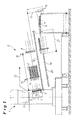
- thermoforming machine 1 In Fig. 1, a thermoforming machine 1 is shown, from the (left) side a plastic film strip 13 is fed to the inlet side, the outlet side according to the registered arrow rewound on a winding roll, not shown becomes.
- the thermoforming machine 1 is a wheeled, automatic Stacking and counting device 6 and this in turn a conveyor belt 14th downstream.
- the thermoforming machine 1 has a tool 3, 4, which is formed in two parts is and from a stationary upper tool part 3 and a exists relative to this movable tool part 4. As explained above, this is movable tool part 4 translational relative to the fixed tool part. 3 movable and otherwise pivotally arranged in the open tool position, to accomplish the demoulding of Article 2 and those of the downstream ones Supply stacking and counting device 6.
- Fig. 1 the open Tool 3, 4 shown with the pivoted movable tool wedge 4.
- the stacking and counting device 6 has a movable catch plate 7, in accordance with the number of movable tool part 4 of the machine. 1 in over- and adjacent rows of mold cavities provided a corresponding Number of tool cavities, in which the article 2 of a only very schematically shown Entformelement 5 discharged or ejected and then stacked into stacked article poles.
- the stacking and counting device 6 further comprises a stacking basket 8, which the Stakes stacked article 2 picks up and from which the article poles then be delivered to the conveyor belt 14. From there you can get one further processing operation are supplied, for. B. a printing machine or a hemming unit.
- the stacking basket 8 is for removing the article rods in the direction of the catch plate. 7 towards a transfer position 15 movable. After the takeover of the article poles the stacking basket 8 can then be in an unloading station remote from the catching plate 7 16 are moved. The stacking basket 8 can out of this position 16 are lowered intermittently, first with a large Senkhub 17 so far, until the bottom row of the article poles in flight with a Abschiebeech 18, and then each with a height 19 of the superimposed Rows of article poles corresponding hub.
- the deportation unit 18, which has a pusher bar 20 for each article bar and toward of the double arrow 21 is movable back and forth, pushes the successive partial strokes lowered article rods on the conveyor belt 14 via.
- the transfer takes place in the Thermoforming machine 1 manufactured article 2 of the catch plate 7 in the stacking basket 8 not directly, but via an intermediate buffer 9.
- the procedure is that after performing a process cycle in the Thermoforming machine 1, the just-made Article 2 of the Entformelement 5 at pivoted movable tool part 4 from the tool 3, 4 deported and be taken over by the catch plate 7.
- the catch plate 7 transports the Article 2 of this single machine cycle to the intermediate buffer 9 and puts them there until a desired number of stacked articles 2 is in the intermediate buffer 9.
- the stacking basket 8 moves to the transfer position 15 and takes over the article poles for further handling such as explained.
- While both the catch plate 7 and the stacking basket 8 by not shown Moving means are movable along a linear path 12, which is Intermediate buffer 9 arranged stationary relative to the stacking and counting device 6. This can be achieved that the stacking of the individual articles 2 by the Catch plate 7 takes place in the intermediate buffer 9 with very small mass forces, so that a quasi-static stacking can take place. This will increase the process stability of the process significantly increased and the articles to be handled are treated very gently. This is especially important if to achieve the lowest possible cycle time the still warm and To handle something soft Article 2 or this formed very thin-walled are.
- the positioned at the end of the travel of the catch plate 7 intermediate buffer 9th takes over each transported by the catch plate 7 Article 2 a production cycle the thermoforming machine 1.
- the intermediate buffer 9 is arranged stationary and is therefore not exposed to any movement. Thus, the stacking can be static respectively.
- the catch plate 7 has a lengthened by a factor of 8 travel what, for the bridging of the interference circuit of the pivotable tool part 4 would be required. This makes it possible, on the one hand, that the required high accelerations and speeds within the interference circuit On the other hand, after leaving the interference circuit the remaining travel used to the high traversing speed decelerate with a small, constant delay.
- the delay is in in each case so small that the mass forces generated from it on the article 2 smaller than the frictional force between the edge of the article and the article overlay.
- Fig. 2 are various movements of the thermoforming machine 1 and the Parts of the downstream stacking and counting device 6 shown over time, where a complete process cycle is shown.
- Fig. 2a first shows how the movable tool part 4 moves.
- the tool 3, 4 is closed, d. H. the movable tool part 4 is in contact with the stationary tool part 3.
- the article 2 is manufactured in the tool 3, 4, and the movable tool part 4 begins to lower down.
- Fig. 2b begins shortly after the lowering movement of the movable tool part 4 (at time 23), the pivoting movement of the Tool part 4 in the position shown in Fig. 1. This is present as soon as the Tilt angle 24 is reached.
- the Entformelement 5 (see Fig. 1) is actuated, whereby the Article 2 are ejected from the tool part 4.
- the course of the hub of the Entformelements 5 over time is shown in FIG. 2c.
- the catch plate 7 during the pivoting movement of the Tool part 4 is not located in the Stör Schl, by the pivoting movement of this part is defined. That is why it is basically necessary that the catch plate 7 is moved with a velocity profile, as shown in Fig. 2d is indicated. Ie. that the catch plate 7 - as soon as it is the pivoting position of Tool part 4 allowed - is accelerated in the direction tool, then on the tool part 4 is moved to remove the article 2 from the tool part 4. When this is done, the catch plate 7 transports the removed articles 2 in the direction of intermediate buffer 9, to which the second marked with crossed lines Speed course is needed.
- Fig. 2e an optimized speed profile for the catch plate 7 is outlined. There it can be seen that the movement of the catch plate 7 from two movement sections 10 and 11, wherein the moving portion 10 by a lower acceleration (less steep course) in relation to the movement section 11 distinguished. Thereafter, the catch plate 7 during the left Movement section 10 accelerates slowly towards the movable tool part 4 and strongly decelerated during the left movement section 11 until it comes to rest in the removal position on the tool part 4. The articles 2 are grabbed here and the catch plate 7 then with relatively high acceleration according to the right movement section 11 in the direction of intermediate buffer 9 accelerates.
- the proposed constant acceleration or deceleration according to Movement sections 10 and 11 proves to be advantageous because on the article 2 during the Einstapeins in the intermediate buffer 9 no forces acting, a falling apart of the pile. Due to the relatively long braking distance the catch plate 7 is the speed of the catch plate 7 during the stacking in the intermediate buffer 9 only a fraction of the speed of the otherwise standard stacking drive.
- thermoforming machine 1 is thus characterized by a separate stacking drive for the stack formation by means of the catch plate 7, which from the Entformelement. 5 (Machine ejector) is decoupled.
- the explained traversing dynamics of the stacking drive, d. H. the catch plate 7, leads to the advantages described.
Abstract
Description
Die Erfindung betrifft ein Verfahren zum Betreiben einer Thermoformmaschine zum Formen von stapelfähigen Artikeln aus Kunststoff, bei dem in einem Werkzeug gefertigte Artikel mit einem Entformelement aus dem Werkzeug entfernt und einer nachgeschalteten Stapel- und Zählvorrichtung zugeführt werden, wobei die Stapel- und Zählvorrichtung eine Fangplatte, mittels der der Abtransport der gefertigten Artikel von der Thermoformmaschine erfolgt, sowie einen Stapelkorb zur Aufnahme gestapelter Artikel vor deren Abtransport aus der Stapel- und Zählvorrichtung aufweist. Des weiteren betrifft die Erfindung eine Thermoformmaschine mit einer nachgeschalteten Stapel- und Zählvorrichtung.The invention relates to a method for operating a thermoforming machine for molding of stackable articles of plastic, in which in a tool manufactured articles with a demolding element removed from the tool and a downstream stacking and counting device are supplied, wherein the Stacking and counting a catch plate, by means of the removal of the manufactured Article of the thermoforming machine takes place, as well as a stacking basket for Recording stacked items before their removal from the stacking and counting device having. Furthermore, the invention relates to a thermoforming machine with a downstream stacking and counting device.
Ein Verfahren zum Betreiben einer Thermoformmaschine der gattungsgemäßen Art ist aus der DE 198 48 628 C2 bekannt. Dort werden zwischen den relativ zueinander beweglichen Teilen eines Werkzeugs Kunststoffartikel (beispielsweise Margarineschalen, Trinkbecher, Behälterdeckel) aus thermoplastischen Kunststofffolien und Verbundfolien produziert. Dabei werden in der geschlossenen Stellung des aus Ober- und Unter-Werkzeug bestehenden Werkzeugs die Artikel geformt, dann gestanzt und dann bei geöffneter Stellung des Werkzeugs aus diesem heraus und in eine nachgeschaltete Stapel- und Zählvorrichtung gefördert. Das Oberteil des Werkzeugs der Maschine ist an einer starren Querbrücke montiert; das Unterteil des Werkzeugs ist indes höhenbeweglich sowie schwenkbar ausgestaltet. Zum Bewerkstelligen der Schwenkbarkeit des unteren Werkzeugteils besitzt dieses einen Lagerzapfen, dessen Lager in einem vertikal geführten Führungsstück angeordnet ist.A method of operating a thermoforming machine of the generic type Art is known from DE 198 48 628 C2. There are between the relative to each other moving parts of a tool plastic articles (for example Margarine bowls, drinking cup, container lid) made of thermoplastic films and laminated films produced. It will be in the closed position of the tool consisting of upper and lower tools, the articles are shaped, then punched and then with the position of the tool out of this out and fed into a downstream stacking and counting device. The Upper part of the tool of the machine is mounted on a rigid cross-bridge; However, the lower part of the tool is designed to be vertically movable and pivotable. To accomplish the pivoting of the lower tool part has this one journal whose bearing in a vertically guided guide piece is arranged.
Damit die Artikel beim Abstapeln nicht gegen Störkanten des Werkzeugs geraten (beispielsweise im Bereich des Folientransportes), ist für das ausschwenkbare Unterteil des Werkzeugs ein großer Schwenkwinkel von typischerweise 80° erforderlich. Die in der ausgeschwenkten Werkzeugendlage aus der Maschine mittels Entformelementen ausgestoßenen Artikel werden von der dem gekippten Unterteil des Werkzeugs entgegenfahrenden bzw. der dem Unterteil des Werkzeugs zugestellten Fangplatte aufgenommen, um ein reproduzierbares Einstapeln zu ermöglichen. Das Bewegen der Fangplatte abwechselnd auf die Maschine zu und von dieser weg ist erforderlich, um aus dem Störradius bzw. Störbereich im Schwenkweg des Werkzeug-Unterteils zu gelangen.So that the articles do not fall against the edges of the tool when stacking (For example, in the field of film transport), is for the swinging Lower part of the tool requires a large tilt angle of typically 80 °. The in the swung out tool end position of the machine by means of Entformelementen ejected articles are from the tilted lower part of the tool on the opposite or delivered to the lower part of the tool Pick plate added to allow a reproducible stacking. Moving the catch plate alternately on the machine to and from this path is required to get out of the interfering radius or interference area in the pivoting path to get to the bottom of the tool.
Während des Einstapelns gefertigter Artikel von der Thermoformmaschine in die Stapel- und Zählvorrichtung steht das untere Teil des Werkzeugs, d. h. es wird kein Hub und keine Schwenkbewegung ausgeführt. Nach dem Einstapelvorgang wird das Werkzeugunterteil wieder in die vertikale Position zurückgeschwenkt und vertikal in die Position zurückverfahren, in der es mit dem Oberteil des Werkzeugs zusammenwirkt. Bekannt ist es dabei, die Thermoformmaschine so zu betreiben, dass für das Zustellen und das Wegfahren der Fangplatte und zum Bewegen des vertikal bewegbaren und schwenkbaren Werkzeugteils eine Synchronisationsbewegung erfolgt, um die Zykluszeit der Maschine möglichst gering zu halten. Grundsätzlich wird dabei angestrebt, dass die Zykluszeiten zum Verfahren des Werkzeugunterteils, also für dessen Translation und Schwenkbewegung, sowie der Fangplatte und des Entformelements möglichst gering werden, um die Ausstoßleistung der Anlage zu maximieren. During the stacking of fabricated articles from the thermoforming machine into the Stacking and counting device is the lower part of the tool, d. H. it will no stroke and no pivoting movement executed. After the stacking process the lower tool part is swung back into the vertical position and vertically return to the position in which it is with the upper part of the tool interacts. It is known to operate the thermoforming machine so that for the delivery and the driving away of the catch plate and for moving the vertically movable and pivoting tool part a synchronization movement takes place in order to keep the cycle time of the machine as low as possible. Basically, the aim is that the cycle times for the process of Tool lower parts, so for its translation and pivoting movement, as well the catch plate and the Entformelements are as low as possible, the output power to maximize the facility.
Um ein prozesssicheres Einstapeln bzw. eine prozesssichere Stapelbildung in der Stapel- und Zählvorrichtung zu ermöglichen, sind verschiedene Lösungen bekannt geworden, die die Gestaltung der Fangplatte und deren Verschiebung bzw. Bewegung betreffen.In order to ensure process-reliable stacking or process-reliable stacking in the Stacking and counting device to allow different solutions are known become the design of the catch plate and its displacement or movement affect.
Aus der bereits genannten DE 198 48 628 C2 ist ein Verfahren zum Bewegen der Fangplatte bekannt, bei dem diese synchronisiert mit der Bewegung des schwenkbaren Werkzeugunterteils verfahren wird. Wie bereits erläutert, muss die Fangplatte dabei möglichst rasch aus dem Störbereich herausgefahren werden, der durch die Schwenkbewegung des Werkzeugs bedingt ist. Es wird dort daher der Verfahrweg der Fangplatte über den Störradius des Schwenkweges des Werkzeugunterteils hinaus verlängert, wobei die dem Störradius entsprechende erste Wegstrecke der Fangplatte beim Wegfahren derselben mit hoher Beschleunigung bzw. beim Zurückstellen mit hoher Verzögerung zurückgelegt wird und wobei die zweite, verlängerte Wegstrecke mit kleineren Werten für die Beschleunigung bzw. Verzögerung durchfahren wird. Damit wird erreicht, dass die auf den Artikelstapel wirkenden Beschleunigungskräfte immer kleiner als die Reibkräfte zwischen dem Artikelstapel und dessen Auflage sind, so dass ein Auseinanderfallen des Stapels durch die Verfahrdynamik ausgeschlossen werden kann.From the already mentioned DE 198 48 628 C2 is a method for moving the Fangplatte known in which this synchronized with the movement of the pivotable lower tool part is moved. As already explained, the Catch plate are moved out of the sturgeon area as quickly as possible, which is due to the pivoting movement of the tool. It will be there, therefore the traverse path of the catch plate over the Störradius the pivoting of the Tool lower part extended, the corresponding the Störradius first distance of the catch plate when driving away the same with high acceleration or on reset with high delay and where the second extended path with smaller values for the acceleration or delay is passed through. This ensures that the on the Article stack acting acceleration forces always smaller than the friction forces between the stack of articles and its overlay, so that a falling apart of the stack can be excluded by the Verfahrdynamik.
Aus der DE 100 04 553 A1 ist eine Thermoformmaschine mit nachgeschalteter Stapel- und Zählvorrichtung bekannt, die eine Fangplatte aufweist, wobei an dieser Artikel-Haltemittel vorgesehen sind, die als Haltefedern ausgebildet und mit einem solchen Stichmaß voneinander beabstandet sind, bei dem der eingestapelte Artikel lose zwischen komplementären Ausnehmungen der Haltefedern aufgenommen ist. Aus der DE 198 48 627 A1 ist es bekannt, dass sich der Fangplatte hinter ihren die Fertigartikel aufnehmenden Ausformungen für jede Artikelstange zwei parallel voneinander beabstandete Stapelstäbe anschließen, die im Bereich des Kopfendes eines aus der Maschine ausgestoßenen Fertigartikels mit federbelasteten Stapelscharnieren versehen sind. Bei beiden genannten Lösungen kann weitestgehend auf Halteelemente für den Artikelstapel verzichtet werden, was deshalb vorteilhaft ist, weil diese zu Problemen beim Entnehmen der Stapel und prinzipiell zu Verformungen der noch etwas weichen Artikel führen können.From DE 100 04 553 A1 is a thermoforming machine with downstream Stacking and counting device known which has a catch plate, wherein at this Article holding means are provided, which are formed as retaining springs and with such a pitch are spaced apart, wherein the stacked Item added loosely between complementary recesses of the retaining springs is. From DE 198 48 627 A1 it is known that the catch plate behind their finished article receiving formations for each article bar connect two parallel spaced stacking rods in the area of the head end of a finished article ejected from the machine with spring-loaded Stack hinges are provided. In both mentioned solutions can largely dispensed with holding elements for the article stack, which This is why it is advantageous because they cause problems when removing the stack and in principle can lead to deformations of the still somewhat soft article.
Aus der 100 44 228 A1 ist ein Verfahren zum Stapeln von Kunststoffartikeln bekannt, die aus der Thermoformmaschine an die Stapel- und Zählvorrichtung übergeben werden, wobei die sich in den Stapelmagazinen bzw. in der Fangplatte befindlichen Stapel nach dem Einstapeln eines Artikels unter Mitnahme dieses Artikels mittels einer von der Übergabeeinrichtung getrennten Verschiebeeinrichtung um ein Maß verschieben, das größer oder gleich dem Abstandsmaß zwischen den gestapelten Behältern ist. Auch damit soll erreicht werden, dass beim Übergeben von Artikeln in Stapelmagazine oder in eine Fangplatte keine Deformationsgefahr für die Artikel durch das Verschieben des bereits gebildeten Stapels um das Stapelmaß gegeben ist.From the 100 44 228 A1 a method for stacking plastic articles is known which passed from the thermoforming machine to the stacking and counting device which are located in the stacking magazines or in the catch plate Stack after stacking an article taking this article with you by means of a separate from the transfer device displacement device by a measure greater than or equal to the distance between the is stacked containers. Also, it should be achieved that when passing of articles in stack magazines or in a catch plate no risk of deformation for the articles by shifting the already formed stack by the stacking dimension given is.
Einen bedeutenden Einfluss auf die Stapelbildung hat das maschinenzugehörige Entformelement (Auswerfersystem), durch das die geformten Artikel aus dem Werkzeug in die zugestellte Fangplatte der Stapel- und Zählvorrichtung transportiert werden. Wegen der angestrebten Ausstoßleistung der Thermoformmaschine wird eine kleine Verfahrzeit des Entformelements angestrebt, wobei Verfahrgeschwindigkeiten von 2 m/s und Beschleunigungen bzw. Verzögerungen von 20 m/s2 nicht ungewöhnlich sind. Diese Prozessparameter haben jedoch insbesondere bei flachen Behältern, Deckeln usw. folgende Nachteile:A significant influence on the stack formation has the machine-related Entformerungselement (ejector system) through which the molded articles are transported from the tool in the delivered catch plate of the stacking and counting device. Because of the desired output of the thermoforming machine, a small travel time of the Entformelements is sought, with traversing speeds of 2 m / s and accelerations or decelerations of 20 m / s 2 are not uncommon. However, these process parameters have the following disadvantages, in particular in the case of flat containers, covers, etc.
Die Einstapelimpulse bewirken ein Auseinanderfallen bzw. Auseinanderrutschen des Artikelstapels, insbesondere am Stapelanfang. Um diese Auswirkungen zu vermindern, werden zu den entsprechenden Halteelementen (s. die oben beschriebenen Lösungen im Stand der Technik) Klemmelemente eingesetzt. Insbesondere bei dünnwandigen Artikeln besteht jedoch durch die Einstapelimpulse die Gefahr der Verformung des zuletzt und des zuvor gestapelten Artikels. The stacking pulses cause a falling apart or slipping apart the stack of articles, especially at the beginning of the stack. To this effect too reduce to the corresponding holding elements (see the above-described Solutions in the prior art) clamping elements used. Especially in thin-walled articles, however, consists of the Einapelimpulse the Risk of deformation of the last and previously stacked article.
Die bekannten Verfahren zum Betreiben einer Thermoformmaschine mit nachgeschalteter Stapel- und Zählvorrichtung haben daher übereinstimmend die nachteiligen Eigenschaften, dass das Einstapeln der gefertigten Artikel unter beachtlichen Massenkräften erfolgt, was die Prozesssicherheit des Verfahren negativ beeinträchtigt. Kleinere Einstapelgeschwindigkeiten, die mit geringeren Massenkräften einhergehen würden, verbieten sich aufgrund ökonomischer Überlegungen, die eine schnelle Bewegung der gefertigten Artikel fordern.The known method for operating a thermoforming machine with downstream Stacking and counting device have therefore coincidentally the disadvantageous Characteristics that the stacking of the manufactured articles under considerable Mass forces takes place, which adversely affects the process reliability of the process. Smaller stacking speeds, with lower mass forces would go along, forbid due to economic considerations, the demand a fast movement of the manufactured articles.
Der Erfindung liegt daher die Aufgabe zugrunde, ein Verfahren zum Betreiben einer Thermoformmaschine mit nachgeschalteter Stapel- und Zählvorrichtung sowie eine solche Thermoformmaschine zu schaffen, die die aus dem Stand der Technik bekannten Nachteile nicht mehr aufweist.The invention is therefore based on the object, a method for operating a Thermoforming machine with downstream stacking and counting device as well to create such a thermoforming machine, which is that of the prior art has no longer known disadvantages.
Die Lösung dieser Aufgabe durch die Erfindung ist verfahrensgemäß dadurch gekennzeichnet, dass die Fangplatte im Werkzeug gefertigte Artikel einem Zwischenpuffer, insbesondere einem einzigen Zwischenpuffer, zuführt, in dem eine Anzahl gestapelter Artikel angesammelt werden, und dass eine im Zwischenpuffer gewünschte Anzahl gestapelter Artikel intermittierend vom Zwischenpuffer in den Stapelkorb verbracht oder transportiert wird.The solution of this problem by the invention is according to the method characterized that the catch plate made in the tool an intermediate buffer, in particular a single intermediate buffer, in which one Number of stacked items to be accumulated, and one in the intermediate buffer desired number of stacked articles intermittently from the intermediate buffer into the Stacking basket is spent or transported.
Bevorzugt ist dabei vorgesehen, dass die Fangplatte jeweils nur die in einem einzigen Fertigungszyklus der Thermoformmaschine hergestellten Artikel dem Zwischenpuffer zuführt.It is preferably provided that the catch plate in each case only in a single Production cycle of the thermoforming machine manufactured article the intermediate buffer supplies.
Eine Weiterbildung sieht vor, dass vor dem Entfernen des Artikels aus dem Werkzeug ein Teil des Werkzeugs, insbesondere ein Unterwerkzeugteil, um einen vorgegebenen Winkel in eine der Fangplatte zugestellte Position geschwenkt wird. Hiernach kommt also das beschriebene Verfahren mit schwenkbarem Werkzeugunterteil zum Einsatz. Dabei ist mit Vorteil vorgesehen, dass die Bewegung der Fangplatte zur Öffnungs- und Schließhubbewegung des Werkzeugs sowie zur Schwenkbewegung des einen Teils des Werkzeugs synchronisiert erfolgt, wie es als solches im Stand der Technik bekannt ist.A continuing education provides that before removing the article from the tool a part of the tool, in particular a lower tool part, to a predetermined Angle is pivoted in one of the catch plate delivered position. After that comes the method described with pivoting tool lower part for use. It is provided with advantage that the movement of Catch plate for the opening and closing movement of the tool as well as for Pivoting movement of one part of the tool is synchronized as it is as such is known in the art.
Das Auftreten höherer Massenkräfte wird weiterbildungsgemäß dadurch verhindert, dass die Bewegung der Fangplatte von der dem Werkzeug zugeordneten Position zu der dem Zwischenpuffer zugeordneten Position aus zwei Bewegungsabschnitten besteht, die durch unterschiedliche, vorzugsweise jeweils konstante, Beschleunigungen bzw. Verzögerungen gekennzeichnet sind.The occurrence of higher mass forces is prevented by further education, that the movement of the catch plate of the tool assigned Position to the intermediate buffer assigned position of two movement sections consists of different, preferably in each case constant, Accelerations or delays are marked.
Die Thermoformmaschine mit einer nachgeschalteten Stapel- und Zählvorrichtung zum Formen und Abtransportieren von stapelfähigen Artikeln aus Kunststoff ist so ausgestaltet, dass die Thermoformmaschine ein Werkzeug aufweist, das mit einem Entformelement für gefertigte Artikel aus dem Werkzeug versehen ist; die Stapel- und Zählvorrichtung weist eine Fangplatte auf, mit der gefertigte Artikel aus der Thermoformmaschine abgeführt werden können, sowie einen Stapelkorb, der zur Aufnahme einer Anzahl gestapelter Artikel geeignet ist. Erfindungsgemäß ist diese Thermoformmaschine gekennzeichnet durch einen Zwischenpuffer, insbesondere durch einen einzigen Zwischenpuffer, für die Aufnahme einer Anzahl gestapelter Artikel, der zwischen Fangplatte und Stapelkorb angeordnet ist.The thermoforming machine with a downstream stacking and counting device for shaping and transporting stackable articles made of plastic is so configured such that the thermoforming machine has a tool that with a Entformelement is provided for manufactured articles from the tool; the Stacking and counting device has a catch plate, with the finished article can be removed from the thermoforming machine, and a stacking basket, which is suitable for receiving a number of stacked articles. According to the invention this thermoforming machine is characterized by an intermediate buffer, in particular through a single intermediate buffer, for taking a number stacked article arranged between catch plate and stacking basket.
Bevorzugt ist der Zwischenpuffer ortsfest angeordnet, und es sind Bewegungsmittel vorhanden, mit denen die Fangplatte und der Stapelkorb translatorisch bewegt werden können.Preferably, the intermediate buffer is arranged stationary, and there are moving means present, with which the catch plate and the stacking basket moves translationally can be.
Dabei sind mit Vorteil die Fangplatte, der Zwischenpuffer und der Stapelkorb auf einer linearen Bahn angeordnet.In this case, the catch plate, the intermediate buffer and the stacking basket are advantageous arranged a linear path.
Mit dem erfindungsgemäßen Vorschlag werden verschiedene Vorteile erzielt: With the proposal according to the invention various advantages are achieved:
Es ist möglich, eine Entkopplung des hochdynamischen und damit ruckbehafteten Maschinenauswerfersystems vom eigentlichen Einstapelvorgang zu erreichen. Dabei sind keine zusätzliche Antriebsachsen erforderlich. Vielmehr kann der Antrieb der Fangplatten für den Einstapelbetrieb, d. h. für das Einstapeln der Artikel, verwendet werden.It is possible to decouple the highly dynamic and thus jerky Machine ejector system to achieve the actual stacking process. There are no additional drive axles required. Rather, the drive can the catch plates for the stacking operation, d. H. for stacking the articles, be used.
Für den Einstapelvorgang selber sind sehr kleine Einstapelgeschwindigkeiten möglich, was die Stapelbildung vorteilhaft und materialschonend gestaltet. Bei entsprechend kleinen Verzögerungen, die durch die erfindungsgemäße Ausgestaltung möglich werden, sind die Massenkräfte der Artikel kleiner als die Reibkraft zwischen Artikel und Auflage, so dass die Stapelbildung mit hoher Prozesssicherheit erreicht werden kann. Durch eine konstante Verzögerung der Fangplatte ist ein sehr harmonischer Stapelbildungsprozess möglich, wobei durch den ortsfest angeordneten Zwischenpuffer eine statische Stapelbildung erfolgen kann.For the stacking process itself are very small stacking speeds possible, which makes the stacking advantageous and gentle on materials. at correspondingly small delays caused by the inventive design become possible, the mass forces of the articles are smaller than the frictional force between article and edition, allowing stacking with high process reliability can be achieved. By a constant delay of the catch plate is a very harmonic stacking process possible, being fixed by the arranged intermediate buffer can be done static stacking.
Damit wird es möglich, auch besonders schwer zu stapelnde Artikel, wie flache Behälter, Deckel, usw., prozesssicher zu stapeln.This makes it possible, even very difficult to stack articles, such as flat Container, lid, etc., process-safe stacking.
In der Zeichnung ist ein Ausführungsbeispiel der Erfindung dargestellt. Es zeigen:
- Fig. 1
- schematisch in der Seitenansicht eine Thermoformmaschine mit nachgeschalteter Stapel- und Zählvorrichtung für abzustapelnde Becher;
- Fig. 2a
- den Verlauf des Hubs des beweglichen Werkzeugteils über der Zeit;
- Fig. 2b
- den Verlauf des Kippwinkels des beweglichen Werkzeugteils über der Zeit;
- Fig. 2c
- den Verlauf des Hubs des Entformelements (Werkzeug-Auswerfer) über der Zeit;
- Fig. 2d
- den Verlauf der Geschwindigkeit der Fangplatte über der Zeit gemäß einer ersten Möglichkeit; und
- Fig. 2e
- den Verlauf der Geschwindigkeit der Fangplatte über der Zeit gemäß einer verbesserten Möglichkeit.
- Fig. 1
- schematically in the side view of a thermoforming machine with downstream stacking and counting device for cups to be stacked;
- Fig. 2a
- the course of the stroke of the movable tool part over time;
- Fig. 2b
- the course of the tilt angle of the movable tool part over time;
- Fig. 2c
- the course of the stroke of the Entformelements (tool ejector) over time;
- Fig. 2d
- the course of the speed of the catch plate over time according to a first possibility; and
- Fig. 2e
- the course of the speed of the catch plate over time according to an improved possibility.
In Fig. 1 ist eine Thermoformmaschine 1 dargestellt, der von der (linken) Seite her ein Kunststoff-Folienband 13 einlaufseitig zugeführt wird, das auslaufseitig gemäß dem eingetragenen Pfeil auf einer nicht dargestellten Wickelrolle wieder aufgewickelt wird. Der Thermoformmaschine 1 ist eine auf Rädern verfahrbare, automatische Stapel- und Zählvorrichtung 6 und dieser wiederum ein Transportband 14 nachgeschaltet.In Fig. 1, a thermoforming machine 1 is shown, from the (left) side a plastic film strip 13 is fed to the inlet side, the outlet side according to the registered arrow rewound on a winding roll, not shown becomes. The thermoforming machine 1 is a wheeled, automatic Stacking and counting device 6 and this in turn a conveyor belt 14th downstream.
Die Thermoformmaschine 1 weist ein Werkzeug 3, 4 auf, das zweiteilig ausgebildet
ist und aus einem ortsfest angeordneten oberen Werkzeugteil 3 sowie einem
relativ zu diesem beweglichen Werkzeugteil 4 besteht. Wie oben erläutert, ist das
bewegliche Werkzeugteil 4 translatorisch relativ zum ortsfesten Werkzeugteil 3
beweglich und im übrigen in geöffneter Werkzeugposition verschwenkbar angeordnet,
um die Entformung der Artikel 2 zu bewerkstelligen und diese der nachgeschalteten
Stapel- und Zählvorrichtung 6 zuzuführen. In Fig. 1 ist das geöffnete
Werkzeug 3, 4 mit dem verschwenkten beweglichen Werkzeugkeil 4 gezeigt.The thermoforming machine 1 has a tool 3, 4, which is formed in two parts
is and from a stationary upper tool part 3 and a
exists relative to this movable tool part 4. As explained above, this is
movable tool part 4 translational relative to the fixed tool part. 3
movable and otherwise pivotally arranged in the open tool position,
to accomplish the demoulding of
Die Stapel- und Zählvorrichtung 6 hat eine verfahrbar angeordnete Fangplatte 7,
die entsprechend der Anzahl der im beweglichen Werkzeugteil 4 der Maschine 1
in über- und nebeneinanderliegenden Reihen vorgesehenen Formnester eine entsprechende
Anzahl von Werkzeugkavitäten aufweist, in die die Artikel 2 von einem
nur sehr schematisch dargestellten Entformelement 5 ausgebracht bzw. ausgestoßen
und dann zu gestapelten Artikelstangen ineinandergestapelt werden. The stacking and counting device 6 has a
Die Stapel- und Zählvorrichtung 6 weist weiterhin einen Stapelkorb 8 auf, der die
Stangen gestapelter Artikel 2 aufnimmt und von dem aus die Artikelstangen dann
auf das Transportband 14 abgegeben werden. Von dort aus können sie einem
weiteren Bearbeitungsvorgang zugeführt werden, z. B. einer Bedruckmaschine
oder einem Bördelaggregat.The stacking and counting device 6 further comprises a stacking
Der Stapelkorb 8 ist zur Abnahme der Artikelstangen in Richtung zur Fangplatte 7
hin bis zu einer Übergabeposition 15 verfahrbar. Nach der Übernahme der Artikelstangen
kann der Stapelkorb 8 dann in eine von der Fangplatte 7 entfernte Entladestation
16 verfahren werden. Der Stapelkorb 8 kann aus dieser Position 16 heraus
taktweise abgesenkt werden, und zwar zunächst mit einem großen Senkhub
17 soweit, bis die untere Reihe der Artikelstangen in Flucht mit einer Abschiebeeinheit
18 liegt, und danach jeweils mit einem einem Höhenmaß 19 der übereinanderliegenden
Reihen von Artikelstangen entsprechenden Hub. Die Abschiebeeinheit
18, die für jede Artikelstange einen Abschieberstab 20 besitzt und in Richtung
des Doppelpfeils 21 hin und her bewegbar ist, schiebt die in Teilhüben sukzessive
abgesenkten Artikelstangen auf das Transportband 14 über.The stacking
Zum Erreichen der oben beschriebenen Vorteile erfolgt die Übergabe der in der
Thermoformmaschine 1 gefertigten Artikel 2 von der Fangplatte 7 in den Stapelkorb
8 nicht direkt, sondern über einen Zwischenpuffer 9.To achieve the advantages described above, the transfer takes place in the
Thermoforming machine 1 manufactured
Dabei wird so vorgegangen, dass nach Durchführung eines Prozesszyklus in der
Thermoformmaschine 1 die soeben gefertigten Artikel 2 vom Entformelement 5 bei
geschwenktem beweglichen Werkzeugteil 4 aus dem Werkzeug 3, 4 abgeschoben
und von der Fangplatte 7 übernommen werden. Die Fangplatte 7 transportiert die
Artikel 2 dieses einzigen Maschinenzyklus zum Zwischenpuffer 9 und legt sie dort
ab, bis sich im Zwischenpuffer 9 eine gewünschte Anzahl gestapelter Artikel 2 befindet.
Ist die gewünschte Anzahl erreicht, verfährt der Stapelkorb 8 zur Übergabeposition
15 und übernimmt die Artikelstangen zur weiteren Handhabung wie
erläutert.The procedure is that after performing a process cycle in the
Thermoforming machine 1, the just-made
Während sowohl die Fangplatte 7 als auch der Stapelkorb 8 durch nicht dargestellte
Bewegungsmittel entlang einer linearen Bahn 12 beweglich sind, ist der
Zwischenpuffer 9 relativ zur Stapel- und Zählvorrichtung 6 ortfest angeordnet.
Damit kann erreicht werden, dass das Einstapeln der einzelnen Artikel 2 durch die
Fangplatte 7 in den Zwischenpuffer 9 mit sehr kleinen Massenkräften erfolgt, so
dass eine quasi statische Stapelbildung erfolgen kann. Hierdurch wird die Prozessstabilität
des Verfahrens entscheidend erhöht und die zu handhabenden Artikel
werden sehr schonend behandelt. Dies ist insbesondere dann von Bedeutung,
wenn zum Erreichen einer möglichst niedrigen Zykluszeit die noch warmen und
etwas weichen Artikel 2 zu handhaben bzw. diese sehr dünnwandig ausgebildet
sind.While both the
Der am Ende des Verfahrweges der Fangplatte 7 positionierte Zwischenpuffer 9
übernimmt jeden durch die Fangplatte 7 transportierten Artikel 2 eines Fertigungszyklus
der Thermoformmaschine 1. Der Zwischenpuffer 9 ist ortsfest angeordnet
und wird folglich keiner Bewegung ausgesetzt. Somit kann die Stapelbildung statisch
erfolgen.The positioned at the end of the travel of the
Die Fangplatte 7 hat einen etwa um den Faktor 8 verlängerten Verfahrweg gegenüber
dem, was für die Überbrückung des Störkreises des verschwenkbaren Werkzeugteils
4 erforderlich wäre. Hierdurch wird es einerseits möglich, dass die erforderlichen
hohen Beschleunigungen und Geschwindigkeiten innerhalb des Störkreises
gefahren werden können, andererseits wird nach dem Verlassen des Störkreises
der verbleibende Verfahrweg genutzt, um die hohe Verfahrgeschwindigkeit
mit einer kleinen, konstanten Verzögerung abzubremsen. Die Verzögerung ist in
jedem Falle so klein, dass die daraus erzeugten Massenkräfte auf den Artikel 2
kleiner sind als die Reibkraft zwischen Artikelrand und Artikelauflage. The
In Fig. 2 sind verschiedene Bewegungen der Thermoformmaschine 1 sowie der Teile der nachgeschalteten Stapel- und Zählvorrichtung 6 über der Zeit gezeigt, wobei ein kompletter Prozesszyklus dargestellt ist.In Fig. 2 are various movements of the thermoforming machine 1 and the Parts of the downstream stacking and counting device 6 shown over time, where a complete process cycle is shown.
Aus Fig. 2a geht zunächst hervor, wie sich das bewegliche Werkzeugteil 4 bewegt.
In dem mit der Bezugsziffer 22 bezeichneten Hub ist das Werkzeug 3, 4 geschlossen,
d. h. das bewegliche Werkzeugteil 4 befindet sich in Anlage an das
ortsfeste Werkzeugteil 3. Zum Zeitpunkt 23 ist der Artikel 2 im Werkzeug 3, 4 gefertigt,
und das bewegliche Werkzeugteil 4 beginnt, sich nach unten abzusenken.From Fig. 2a first shows how the movable tool part 4 moves.
In the stroke designated by the
Wie aus Fig. 2b gesehen werden kann, beginnt kurz nach der Absenkbewegung
des beweglichen Werkzeugteils 4 (zum Zeitpunkt 23) die Schwenkbewegung des
Werkzeugteils 4 in die in Fig. 1 dargestellte Position. Diese liegt vor, sobald der
Kippwinkel 24 erreicht ist.As can be seen from Fig. 2b, begins shortly after the lowering movement
of the movable tool part 4 (at time 23), the pivoting movement of the
Tool part 4 in the position shown in Fig. 1. This is present as soon as the
Sobald dies der Fall ist, wird das Entformelement 5 (s. Fig. 1) betätigt, wodurch die
Artikel 2 aus dem Werkzeugteil 4 ausgestoßen werden. Der Verlauf des Hubs des
Entformelements 5 über der Zeit ist der Fig. 2c zu entnehmen.Once this is the case, the Entformelement 5 (see Fig. 1) is actuated, whereby the
Wesentlich ist, dass sich die Fangplatte 7 während der Verschwenkbewegung des
Werkzeugteils 4 nicht in dem Störbereich befindet, der durch die Verschwenkbewegung
dieses Teils definiert wird. Deswegen ist es grundsätzlich notwendig, dass
die Fangplatte 7 mit einem Geschwindigkeitsprofil bewegt wird, wie es in Fig. 2d
angedeutet ist. D. h. dass die Fangplatte 7 - sobald es die Schwenkposition des
Werkzeugteils 4 erlaubt - in Richtung Werkzeug beschleunigt wird, sich dann auf
das Werkzeugteil 4 zu bewegt, um die Artikel 2 aus dem Werkzeugteil 4 zu entnehmen.
Ist dies geschehen, transportiert die Fangplatte 7 die entnommenen Artikel
2 in Richtung Zwischenpuffer 9, wozu der zweite mit gekreuzten Linien gekennzeichnete
Geschwindigkeitsverlauf benötigt wird. It is essential that the
In Fig. 2e ist ein optimiertes Geschwindigkeitsprofil für die Fangplatte 7 skizziert.
Dort ist zu sehen, dass die Bewegung der Fangplatte 7 aus zwei Bewegungsabschnitten
10 und 11 besteht, wobei sich der Bewegungsabschnitt 10 durch eine
geringere Beschleunigung (weniger steiler Verlauf) im Verhältnis zum Bewegungsabschnitt
11 auszeichnet. Danach wird die Fangplatte 7 während des linken
Bewegungsabschnitts 10 langsam in Richtung bewegliches Werkzeugteil 4 beschleunigt
und während des linken Bewegungsabschnitts 11 stark abgebremst, bis
es in der Entnahmeposition am Werkzeugteil 4 zu liegen kommt. Die Artikel 2
werden hier gegriffen und die Fangplatte 7 anschließend mit relativ großer Beschleunigung
gemäß dem rechten Bewegungsabschnitt 11 in Richtung Zwischenpuffer
9 beschleunigt. Damit eine möglichst weiche und ruckfreie Abstapelung der
sich in der Fangplatte 7 befindlichen Artikel 2 im Zwischenpuffer 9 ergeben kann,
wird die Fangplatte 7 mit relativ geringer negativer Beschleunigung gemäß dem
rechten Bewegungsabschnitt 10 abgebremst, so dass die Stapelbildung bei minimalen
Verfahrgeschwindigkeiten und somit minimalen Massenkräften erfolgen
kann.In Fig. 2e an optimized speed profile for the
Die vorgeschlagene konstante Beschleunigung bzw. Verzögerung gemäß den
Bewegungsabschnitten 10 und 11 erweist sich als vorteilhaft, weil auf die Artikel 2
während des Einstapeins im Zwischenpuffer 9 keine Kräfte wirken, die ein Auseinanderfallen
des Stapels bedingen würden. Durch den relativ langen Abbremsweg
der Fangplatte 7 beträgt die Geschwindigkeit der Fangplatte 7 während des Einstapelns
in den Zwischenpuffer 9 nur einen Bruchteil der Geschwindigkeit des
sonst üblichen Einstapelantriebs.The proposed constant acceleration or deceleration according to
Die Thermoformmaschine 1 zeichnet sich also durch einen separaten Einstapelantrieb
für die Stapelbildung mittels der Fangplatte 7 aus, die vom Entformelement 5
(Maschinenauswerfer) entkoppelt ist. Die erläuterte Verfahrdynamik des Einstapelantriebs,
d. h. der Fangplatte 7, führt zu den beschriebenen Vorteilen. The thermoforming machine 1 is thus characterized by a separate stacking drive
for the stack formation by means of the
Die abzustapelnden Artikel 2 werden insgesamt daher sehr schonend behandelt.
Durch die geringen Massenkräfte wird es weiterhin möglich, auch sehr schwer
stapelbare Artikel 2 zu handhaben.The
Beim Einstapeln des Artikels 2 in den Zwischenpuffer 9 bewirkt die kleine, konstante
Verzögerung nicht nur eine Stapelbildung ohne ein Auseinanderfallen bzw.
Auseinanderrutschen der Artikel 2 am Anfang des Stapels, sondern es wird ebenfalls
eine plane koaxiale Anlage von aktuell gestapelten und zuvor gestapelten
Artikeln 2 über den gesamten Stapelhub gewährleistet. So wird ein Verspringen
der Artikel 2 am Stapelende vermieden. When stacking the
- 11
- ThermoformmaschineThermoforming machine
- 22
- stapelfähiger Artikelstackable article
- 3, 43, 4
- WerkzeugTool
- 33
- ortsfestes Werkzeugteilstationary tool part
- 44
- bewegliches Werkzeugteilmovable tool part
- 55
- EntformelementEntformelement
- 66
- Stapel- und ZählvorrichtungStacking and counting device
- 77
- Fangplattecatch plate
- 88th
- Stapelkorbstacking basket
- 99
- Zwischenpufferintermediate buffer
- 1010
- Bewegungsabschnittmovement section
- 1111
- Bewegungsabschnittmovement section
- 1212
- lineare Bahnlinear path
- 1313
- Kunststoff-FolienbandPlastic film band
- 1414
- Transportbandconveyor belt
- 1515
- ÜbergabepositionTransfer position
- 1616
- Entladestationunloading
- 1717
- SenkhubSenkhub
- 1818
- AbschiebeeinheitAbschiebeeinheit
- 1919
- Höhenmaßheight dimension
- 2020
- AbschieberstabAbschieberstab
- 2121
- Doppelpfeildouble arrow
- 2222
- Hubstroke
- 2323
- Zeitpunkttime
- 2424
- Kippwinkeltilt angle
Claims (9)
dadurch gekennzeichnet, dass die Fangplatte (7) im Werkzeug (3, 4) gefertigte Artikel (2) einem Zwischenpuffer (9) zuführt, in dem eine Anzahl gestapelter Artikel (2) angesammelt wird, und dass eine im Zwischenpuffer (9) gewünschte Anzahl gestapelter Artikel (2) intermittierend vom Zwischenpuffer (9) in den Stapelkorb (8) verbracht wird.Method for operating a thermoforming machine (1) for forming stackable articles (2) made of plastic, in which articles (2) manufactured in a tool (3, 4) are removed from the tool (3, 4) with a demoulding element (5) and a stacking and counting device (6) are fed, wherein the stacking and counting device (6) has a catch plate (7), by means of the removal of the finished article (2) from the thermoforming machine (1), and a stacking basket (8 ) for receiving stacked articles (2) before being transported away from the stacking and counting device (6),
characterized in that the catch plate (7) in the tool (3, 4) fabricated article (2) an intermediate buffer (9) supplies, in which a number of stacked articles (2) is accumulated, and that in the intermediate buffer (9) desired number stacked article (2) is intermittently from the intermediate buffer (9) in the stacking basket (8) is spent.
dadurch gekennzeichnet, dass die Fangplatte (7) jeweils nur die in einem einzigen Fertigungszyklus der Thermoformmaschine (1) hergestellten Artikel (2) dem Zwischenpuffer (9) zuführt. Method according to claim 1,
characterized in that the catch plate (7) in each case only in a single production cycle of the thermoforming machine (1) produced article (2) the intermediate buffer (9) supplies.
dadurch gekennzeichnet, dass vor dem Entfernen des Artikels (2) aus dem Werkzeug (3, 4) ein Teil (4) des Werkzeugs (3, 4), insbesondere ein Unterwerkzeugteil, um einen vorgegebenen Winkel in eine der Fangplatte (7) zugestellte Position geschwenkt wird.Method according to claim 1 or 2,
characterized in that prior to removal of the article (2) from the tool (3, 4) a part (4) of the tool (3, 4), in particular a lower tool part, by a predetermined angle in one of the catch plate (7) delivered position is pivoted.
dadurch gekennzeichnet, dass die Bewegung der Fangplatte (7) zur Öffnungs- und Schließhubbewegung des Werkzeugs (3, 4) sowie zur Schwenkbewegung des einen Teils (4) des Werkzeugs (3, 4) synchronisiert erfolgt.Method according to claim 3,
characterized in that the movement of the catch plate (7) for the opening and Schließhubbewegung of the tool (3, 4) and the pivotal movement of the one part (4) of the tool (3, 4) is synchronized.
dadurch gekennzeichnet, dass die Bewegung der Fangplatte (7) von der dem Werkzeug (3, 4) zugeordneten Position zu der dem Zwischenpuffer (9) zugeordneten Position in zwei Bewegungsabschnitte (10, 11) mit unterschiedlichen Beschleunigungen oder Verzögerungen unterteilt wird.Method according to one of claims 1 to 4,
characterized in that the movement of the catch plate (7) from the position associated with the tool (3, 4) to the position associated with the intermediate buffer (9) is subdivided into two movement sections (10, 11) with different accelerations or decelerations.
dadurch gekennzeichnet, dass die beiden Bewegungsabschnitte (10, 11) der Fangplatte (7) jeweils mit einer konstanten Beschleunigung oder Verzögerung durchfahren werden.Method according to claim 5,
characterized in that the two movement sections (10, 11) of the catch plate (7) are each traversed with a constant acceleration or deceleration.
gekennzeichnet durch
einen Zwischenpuffer (9) für die Aufnahme einer Anzahl gestapelter Artikel (2), der zwischen Fangplatte (7) und Stapelkorb (8) angeordnet ist.Thermoforming machine (1) with a downstream stacking and counting device (6) for forming and transporting off stackable articles (2) made of plastic, wherein the thermoforming machine (1) comprises a tool (3, 4) provided with a demolding element (5) for fabricated article (2) from the tool (3, 4) is provided, and wherein the stacking and counting device (6) a catch plate (7) can be removed with the fabricated article (2) from the thermoforming machine (1), and a stacking basket (8) suitable for receiving a number of stacked articles (2),
marked by
an intermediate buffer (9) for receiving a number of stacked articles (2) arranged between catch plate (7) and stacking basket (8).
dadurch gekennzeichnet, dass der Zwischenpuffer (9) ortsfest angeordnet ist und Bewegungsmittel zur translatorischen Bewegung von Fangplatte (7) und Stapelkorb (8) vorhanden sind.Thermoforming machine according to claim 7,
characterized in that the intermediate buffer (9) is arranged stationary and movement means for the translational movement of the catch plate (7) and stacking basket (8) are present.
dadurch gekennzeichnet, dass die Fangplatte (7), der Zwischenpuffer (9) und der Stapelkorb (8) auf einer linearen Bahn (12) angeordnet sind.Thermoforming machine according to claim 7 or 8,
characterized in that the catch plate (7), the intermediate buffer (9) and the stacking basket (8) are arranged on a linear path (12).
Applications Claiming Priority (2)
| Application Number | Priority Date | Filing Date | Title |
|---|---|---|---|
| DE102004011002 | 2004-03-06 | ||
| DE102004011002A DE102004011002A1 (en) | 2004-03-06 | 2004-03-06 | Method for operating a thermoforming machine and thermoforming machine |
Publications (2)
| Publication Number | Publication Date |
|---|---|
| EP1570972A1 true EP1570972A1 (en) | 2005-09-07 |
| EP1570972B1 EP1570972B1 (en) | 2007-03-28 |
Family
ID=34745421
Family Applications (1)
| Application Number | Title | Priority Date | Filing Date |
|---|---|---|---|
| EP05003006A Revoked EP1570972B1 (en) | 2004-03-06 | 2005-02-12 | Thermoforming machine with buffer and process for handling the same |
Country Status (3)
| Country | Link |
|---|---|
| EP (1) | EP1570972B1 (en) |
| AT (1) | ATE358011T1 (en) |
| DE (2) | DE102004011002A1 (en) |
Cited By (1)
| Publication number | Priority date | Publication date | Assignee | Title |
|---|---|---|---|---|
| EP2100835A1 (en) | 2008-03-11 | 2009-09-16 | Amut S.p.A. | Machine and process for stacking thermoformed articles |
Families Citing this family (1)
| Publication number | Priority date | Publication date | Assignee | Title |
|---|---|---|---|---|
| ATE555892T1 (en) | 2009-05-14 | 2012-05-15 | Gabler Thermoform Gmbh & Co Kg | DEVICE FOR STACKING FINISHED ITEMS MADE OF THERMOPLASTIC PLASTIC |
Citations (4)
| Publication number | Priority date | Publication date | Assignee | Title |
|---|---|---|---|---|
| DE3346628A1 (en) * | 1983-12-23 | 1985-07-11 | Adolf Illig Maschinenbau Gmbh & Co, 7100 Heilbronn | Device for forming, punching and stacking parts made of thermoplastics sheet |
| EP0995581A2 (en) * | 1998-10-22 | 2000-04-26 | Gabler Maschinenbau GmbH | Warmumformmaschine |
| EP1000887A1 (en) * | 1998-11-13 | 2000-05-17 | Illig, Adolf Maschinenbau GmbH & Co. | Device for picking up and stacking of thermoplastic containers |
| DE10256141A1 (en) * | 2002-06-21 | 2004-02-05 | Walter Lauermann | Stacking process for plastic shell-like container preforms such as beakers in which an ejector plate for ejection of a completed stack also acts as a support for a new stack behind it |
Family Cites Families (1)
| Publication number | Priority date | Publication date | Assignee | Title |
|---|---|---|---|---|
| DE10052759C2 (en) * | 2000-10-25 | 2002-11-07 | Illig Maschinenbau Adolf | Device for stacking parts made of thermoplastic material |
-
2004
- 2004-03-06 DE DE102004011002A patent/DE102004011002A1/en not_active Withdrawn
-
2005
- 2005-02-12 AT AT05003006T patent/ATE358011T1/en active
- 2005-02-12 EP EP05003006A patent/EP1570972B1/en not_active Revoked
- 2005-02-12 DE DE502005000509T patent/DE502005000509D1/en not_active Revoked
Patent Citations (4)
| Publication number | Priority date | Publication date | Assignee | Title |
|---|---|---|---|---|
| DE3346628A1 (en) * | 1983-12-23 | 1985-07-11 | Adolf Illig Maschinenbau Gmbh & Co, 7100 Heilbronn | Device for forming, punching and stacking parts made of thermoplastics sheet |
| EP0995581A2 (en) * | 1998-10-22 | 2000-04-26 | Gabler Maschinenbau GmbH | Warmumformmaschine |
| EP1000887A1 (en) * | 1998-11-13 | 2000-05-17 | Illig, Adolf Maschinenbau GmbH & Co. | Device for picking up and stacking of thermoplastic containers |
| DE10256141A1 (en) * | 2002-06-21 | 2004-02-05 | Walter Lauermann | Stacking process for plastic shell-like container preforms such as beakers in which an ejector plate for ejection of a completed stack also acts as a support for a new stack behind it |
Cited By (1)
| Publication number | Priority date | Publication date | Assignee | Title |
|---|---|---|---|---|
| EP2100835A1 (en) | 2008-03-11 | 2009-09-16 | Amut S.p.A. | Machine and process for stacking thermoformed articles |
Also Published As
| Publication number | Publication date |
|---|---|
| DE102004011002A1 (en) | 2005-09-22 |
| DE502005000509D1 (en) | 2007-05-10 |
| EP1570972B1 (en) | 2007-03-28 |
| ATE358011T1 (en) | 2007-04-15 |
Similar Documents
| Publication | Publication Date | Title |
|---|---|---|
| DE19727749C2 (en) | Laterally retracting robot for the removal of shaped objects | |
| CH457268A (en) | Device for depositing flat objects in a stack | |
| DE2537279A1 (en) | PALLET UNLOADER | |
| DE3625841A1 (en) | STACKING DEVICE FOR, IN PARTICULAR MANUFACTURED IN A THERMOFORMING MACHINE, PLASTIC DRAWING PARTS | |
| EP0623406B1 (en) | Device for transferring and forwarding container covers made of ferromagnetic material | |
| DE19848628C2 (en) | Method for operating a thermoforming machine | |
| EP0995582B1 (en) | Thermo-forming machine | |
| DE3139828C2 (en) | ||
| EP1570972B1 (en) | Thermoforming machine with buffer and process for handling the same | |
| EP1195337B1 (en) | Method for piling containers made of thermoplastic material and device for executing the method | |
| DE2845676C2 (en) | Device for the automatic layering of laminated iron cores | |
| EP0591099B1 (en) | Method and device for making tied stacks of paper products | |
| DE19509057C2 (en) | Device for transferring and stacking containers deep-drawn and punched out of a thermoplastic plastic film | |
| DE2618950A1 (en) | PLATE TRANSFER MACHINE | |
| DE2648563C2 (en) | Device for stacking flat deep-drawn parts made of thermoplastic material | |
| DE102010035670A1 (en) | High-speed memory | |
| DE102014206988A1 (en) | Method and device for horizontal movement of article groups | |
| DE3822363C2 (en) | ||
| DE102017102913A1 (en) | Apparatus and method for the flexible distribution of packaging | |
| EP1752400A2 (en) | Method of transferring containerstacks to a subsequent machine and a machine for performing said method | |
| DE19933354C1 (en) | Method for stacking containers made of thermoplastic material and device for carrying out the method | |
| EP0995583B1 (en) | Thermoforming machine | |
| DE19861131C2 (en) | Handling device for the transfer of one card at a time | |
| CH473043A (en) | Method for stacking printed sheets transported one after the other and device for carrying it out | |
| EP3011845A1 (en) | Assembly and method for conveying a product flow comprising rod-shaped items of the tobacco industry and container for holding and releasing portions of the product flow |
Legal Events
| Date | Code | Title | Description |
|---|---|---|---|
| PUAI | Public reference made under article 153(3) epc to a published international application that has entered the european phase |
Free format text: ORIGINAL CODE: 0009012 |
|
| AK | Designated contracting states |
Kind code of ref document: A1 Designated state(s): AT BE BG CH CY CZ DE DK EE ES FI FR GB GR HU IE IS IT LI LT LU MC NL PL PT RO SE SI SK TR |
|
| AX | Request for extension of the european patent |
Extension state: AL BA HR LV MK YU |
|
| GRAP | Despatch of communication of intention to grant a patent |
Free format text: ORIGINAL CODE: EPIDOSNIGR1 |
|
| 17P | Request for examination filed |
Effective date: 20060302 |
|
| AKX | Designation fees paid |
Designated state(s): AT DE IT NL |
|
| GRAS | Grant fee paid |
Free format text: ORIGINAL CODE: EPIDOSNIGR3 |
|
| GRAA | (expected) grant |
Free format text: ORIGINAL CODE: 0009210 |
|
| AK | Designated contracting states |
Kind code of ref document: B1 Designated state(s): AT DE IT NL |
|
| REF | Corresponds to: |
Ref document number: 502005000509 Country of ref document: DE Date of ref document: 20070510 Kind code of ref document: P |
|
| PLBI | Opposition filed |
Free format text: ORIGINAL CODE: 0009260 |
|
| PLAX | Notice of opposition and request to file observation + time limit sent |
Free format text: ORIGINAL CODE: EPIDOSNOBS2 |
|
| 26 | Opposition filed |
Opponent name: ADOLF ILLIG MASCHINENBAU GMBH & CO. KG Effective date: 20071220 |
|
| NLR1 | Nl: opposition has been filed with the epo |
Opponent name: ADOLF ILLIG MASCHINENBAU GMBH & CO. KG |
|
| PLAF | Information modified related to communication of a notice of opposition and request to file observations + time limit |
Free format text: ORIGINAL CODE: EPIDOSCOBS2 |
|
| PLAF | Information modified related to communication of a notice of opposition and request to file observations + time limit |
Free format text: ORIGINAL CODE: EPIDOSCOBS2 |
|
| PLBB | Reply of patent proprietor to notice(s) of opposition received |
Free format text: ORIGINAL CODE: EPIDOSNOBS3 |
|
| PGFP | Annual fee paid to national office [announced via postgrant information from national office to epo] |
Ref country code: IT Payment date: 20100219 Year of fee payment: 6 |
|
| RDAF | Communication despatched that patent is revoked |
Free format text: ORIGINAL CODE: EPIDOSNREV1 |
|
| PGFP | Annual fee paid to national office [announced via postgrant information from national office to epo] |
Ref country code: AT Payment date: 20100212 Year of fee payment: 6 Ref country code: DE Payment date: 20100219 Year of fee payment: 6 |
|
| PGFP | Annual fee paid to national office [announced via postgrant information from national office to epo] |
Ref country code: NL Payment date: 20100215 Year of fee payment: 6 |
|
| RDAG | Patent revoked |
Free format text: ORIGINAL CODE: 0009271 |
|
| STAA | Information on the status of an ep patent application or granted ep patent |
Free format text: STATUS: PATENT REVOKED |
|
| 27W | Patent revoked |
Effective date: 20100710 |