TECHNICAL FIELD
The present invention relates to leg massage units
adapted to massage the feet and calves of the user.
BACKGROUND ART
Leg massage units are available which comprise a foot
massage unit for the user to insert his or her feet thereinto
for massaging the feet and a calf massage unit for inserting
the calves thereinto for giving a massage to the calves so that
the parts of the legs below the knees can be massaged (see,
for example, the publication of JP-A No. 2002-238963).
The calf massage unit is fixed to the foot massage unit
and can not therefore be positioned at varying angles or at
varying levels as desired by the user. Accordingly the legs
assuming an unnatural posture are likely to become tired during
massaging, or a massage can not be given to the desired affected
part to result in a lower massage effect.
DISCLOSURE OF THE INVENTION
An object of the present invention is to provide a leg
massage unit comprising a calf massage unit which is made
tiltable and/or slidable upward or downward so as to give an
enhanced massage effect to the user.
To fulfill the above object, the present invention
provides a leg massage unit comprising a foot massage unit for
massaging the feet of the user, and a calf massage unit tiltably
coupled to a base end of the foot massage unit by a connecting
mechanism and adapted to massage the calves of the user. The
connecting mechanism exerts torque acting to move the calf
massage unit toward an upright position relative to the foot
massage unit.
The calf massage unit is made tiltable relative to the
foot massage unit, and the connecting mechanism couples the
calf massage unit to the foot massage unit so as to exert toque
acting to move the calf massage unit toward an upright position
relative to the foot massage unit. Accordingly when the calf
is moved, the calf massage unit follows the movement of the
calf and tilts rearward. Since the calf massage unit is always
held in intimate contact with the calf by the torque acting
to move the calf massage unit toward an upright position, an
enhanced calf massage effect is available.
The calf massage unit is positioned at a variable angle
with the foot massage unit, so that the leg is unlikely to become
tired during massaging.
For example when the user desires to have a massage while
lying on the floor, the calf massage unit can be tilted rearward
through a large angle merely by lying on the floor with his
or her legs placed into the calf massage unit without
manipulating the unit in any way.
Preferably, the calf massage unit is upwardly or
downwardly slidably connected to the foot massage unit by the
connecting mechanism. The calf massage unit can then be
positioned at the level of the calf of the user or a level
desirable for the affected part to be massaged for the massage
unit to give an effective massage.
BRIEF DESCRIPTION OF THE DRAWINGS
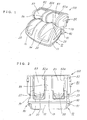
FIG. 1 is a perspective view of a leg massage unit of
the invention.
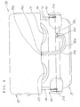
FIG. 2 is a front view of the leg massage unit of the
invention.
FIG. 3 is a side elevation of the leg massage unit of
the invention.
FIG. 4 is a rear view of the leg massage unit of the
invention.
FIG. 5 is a side elevation showing the leg massage unit
in use.
FIG. 6 is aside elevation showing the leg massage unit
in use.
FIG. 7 is a plan view of a foot massage unit.
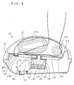
FIG. 8 is a view in section taken along the line X1-X1
in FIG. 7.
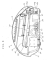
FIG. 9 is a view in section taken along the line X2-X2
in FIG. 7.
FIG. 10 is a view in section taken along the line Y-Y
in FIG. 7.
FIG. 11 is a front view partly in section and showing
a calf massage unit.
FIG. 12 is a view in section taken along the line X-X
in FIG. 11.
FIG. 13 is a view in section taken along the line Y-Y
in FIG. 11.
FIG. 14 is a view showing on an enlarged scale the portion
of FIG. 13 surrounded by a two-dot chain line.
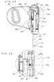
FIG. 15 is an enlarged sectional view of a tilting
portion.
FIG. 16 includes views in section taken along the line
Y-Y in FIG. 15.
FIG. 17 is a front view of hose connectors of the calf
massage unit.
FIG. 18 is a side elevation of the hose connector of the
calf massage unit.
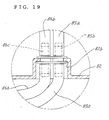
FIG. 19 is a front view showing hose connectors,
according to a different embodiment, of the calf massage unit.
BEST MODE OF CARRYING OUT THE INVENTION
A description will be given with reference to a leg
massage unit 100 which is adapted to give a massage to the feet
and calves of the user.
FIG. 1 is a perspective view of the leg massage unit 100
of the invention, FIG. 2 is a front view of the same, FIG. 3
is a side elevation of the same, FIG. 4 is a rear view of the
same, and FIGS. 5 and 6 are side elevations showing the massage
unit 100 in use.
The leg massage unit 100 comprises a foot massage unit
10 for massaging the feet of the user, more specifically the
parts of the legs below the ankles, and a calf massage unit
80 coupled to the base end of the foot massage unit 10 by a
connecting mechanism 90 tiltably and slidably for massaging
the calves of the user.
The foot massage unit 10, the calf massage unit 80 and
the connecting mechanism 90 for the two units 10, 80 will be
described below in this order.
[Foot Massage Unit 10]
With reference to FIG. 1, the foot massage unit 10 has
a cover 12 made of a resin and having a pair of left and right
recessed footrests 20, 20 each generally U-shaped in cross
section for the user to insert his or her feet (the terminal
ends of the legs below the ankles) thereinto. A center wall
14 is formed as a partition to provide the recessed footrests
20, 20 on opposite sides thereof as shown in FIGS. 1 and 2.
The inner surface of the resin cover 12 providing the footrests
20 is covered with a cloth cover 16.
The connecting mechanism 90 for tiltably supporting the
calf massage unit 80 to be described later has a tilting portion
91 (to be described later) provided on each of opposite side
walls of the rear end of the resin cover 12.
FIG. 7 is a plan view showing the foot massage unit 10
with the cloth cover 16 removed, FIG. 8 is a view in section
taken along the line X1-X1 in FIG. 7, FIG. 9 is a view in section
taken along the line X2-X2 in FIG. 7, and FIG. 10 is a view
in section taken along the line Y-Y in FIG. 7.
The opposite side walls of each recessed footrest 20 are
provided with respective side air bags 21, 21, which are covered
with the cloth cover 16 over the inner side surfaces thereof.
The side air bags 21, 21 are held in communication by a
connecting hose 65, which is connected by air supply hoses 64
to a solenoid valve 62 and a pump 60. The side air bags 21
are made by blow molding and have front and rear expansion
portions 21a, 21b resembling pleats. Alternatively, the air
bags can be made from a nylon fabric laminated with a urethane
sheet
With reference to FIGS. 7 and 8, the connecting hose 65
is disposed in a cavity 65a formed not on the heel side of the
footrest 20 but in the front portion of the bottom wall of each
footrest 20 (at a position where the hose will remain out of
contact with the foot of common size and which is outside the
range of movement of the acupressure rod 32 to be described
later), and is positioned so close to the heater 50 to be
described later as to be subjected to heat exchange therewith
through the bottom wall of the footrest 20. With the
connecting hose 65 thus positioned, the compressed air to be
supplied to the side air bags 21 through the hose 65 can be
heated to ensure an improved thermotherapeutic effect.
Further this arrangement makes it possible to heat the
compressed air without reducing the thermotherapeutic effect
on the soles of the user. On the other hand, if the connecting
hose 65 is allowed to extend through a portion to be in contact
with the sole or heel, the heat from the heater 50 will be
blocked by the hose 65 and encounters difficulty in being
transferred to the sole to result in an impaired
thermotherapeutic effect. Accordingly, the arrangement
described above is desirable.
Although the side air bag 21 is provided on each of
opposite side walls of the recessed footrest 20 as illustrated,
one of the side bags can be made from an elastic member, for
example, of sponge, urethane or like material having
elasticity.
The bottom wall of the footrest 20 is so slanted that
the front end thereof is at a high level with the rear end
thereof positioned at a low level as shown in FIG. 8. This
slope assures the foot of stability when the user places his
or her foot into the recessed footrest 20. The footrest 20
is provided at its rear end with an upstanding wall 23 extending
upward so as to prevent the foot from slipping off the footrest
20. The upstanding wall 23 is recessed toward the rear at the
heel portion in conformity with the shape of the heel.
Preferably, the upstanding wall 23 is 20 to 50 mm in height.
With reference to FIGS. 7, 8 and 10, the bottom wall of
each recessed footrest 20 is provided with massage means 30
for massaging the sole of the user. The massage means 30
comprises, for example, means provided with illustrated
acupressure rods 32, 32. The acupressure rods 32, 32 have
their upper ends projecting upward through respective two
slots 25, 25 formed in the bottom wall of the footrest 20. The
slots 25, 25 extend longitudinally of the footrest 20. Ribs
26 projecting downward are formed along the inner peripheries
of slots 25.
The heater 50 is attached to the rear side of the bottom
wall of the footrest 20. The heater 50 comprises, for example,
a heater wire enclosed with aluminum foil. As shown in FIGS.
7 and 10, the heater 50 can be disposed around the slots 25,
25. When the slot 25 is provided with the rib 26, the heater
50 will not be exposed directly to water or the like even if
the user spills such a liquid over the foot massage unit 10
in error. The rib 26 provided for the slot 25 therefore serves
to protect the heater 50 from water.
The massage means 30 is provided on the rear side of the
bottom wall of the footrest 20 with the two acupressure rods
32, 32 made projectable from inside a case 36 as shown in FIGS.
8 and 10. Disposed inside the case 36 is a rectangular plate
33 provided with the two acupressure rods 32, 32 having a
circular cross section and extending upward therefrom. The
plate 33 is placed on a bottom air bag 34 positioned in a lower
portion of the case 36. The case 36 has an upper opening, which
is closed with the mount plate 40 to be described below. The
acupressure rods 32 extend upward through holes 42 formed in
the mount plate 40. A spring 35 is provided between the mount
plate 40 and the upper surface of the plate 33 for biasing the
plate 33 downward. With the bottom air bag 34 contracted, the
plate 33 is pushed downward to minimize the amount of projection
of the acupressure rods 32, 32.
The bottom air bag 34 can be made, for example, from a
nylon fabric laminated with a urethane sheet. As shown in FIG.
9, the bottom air bag 34 is connected by the air supply hose
64 to the solenoid valve 62 and the pump 60 which are arranged
inside the foot massage unit 10. When compressed air is
supplied from the pump 60 by actuating the solenoid valve 62,
the bottom air bag 34 is inflated, moving the acupressure rods
32 upward. When the air is removed from the bag 34, the rods
32 are moved down by the force of the spring 35.
With reference to FIG. 10, the bottom wall of the resin
cover 12 is raised upward at portions close to the left and
right ends to form rail portions 28, 28 for slidably supporting
the massage means 30. The rail portions 28 have their front
parts positioned at a high level and their rear parts at a low
level in conformity with the slope of the bottom walls of the
recessed footrests 20.
As seen in FIG. 10, the mount plate 40 is made of a metal
plate elongated in the left-right direction and is provided
at opposite ends thereof with respective guides 41, 41 fitting
to and slidable on the rail portions 28, 28. The cases 36,
36 for the left and right massage means 30 are fastened with
screws to the mount plate 40, and the holes 42, 42 for the
acupressure rods 32, 32 to project therethrough are formed in
the mount plate 40. A feed nut 43 is secured to the center
of the mount plate 40 on the upper surface thereof by a nut
fixing member 44. The feed screw 45 to be described later
extends through the feed nut 43 in screw-thread engagement
therewith. The mount plate 40 is movable forward or rearward
on the rail portions 28, 28 by the rotation of the feed screw
45, whereby the massage means 30, 30 mounted on the plate 40
are reciprocatingly movable forward or rearward.
The feed screw 45 extending forward or rearward for
moving the massage means 30 forward or rearward is provided
between the recessed footrests 20, 20, i.e. , inside the center
wall 14 of the resin cover 12 as shown in FIGS. 9 and 10. The
feed screw 45 is supported by a frame 46 provided inside the
resin cover 12 so as to be slanted in conformity with the slope
of the bottom walls of the footrests 20 as shown in FIG. 9.
A pulley 45a mounted on the rear end of the screw 45 is coupled
to a pulley 47b on a motor 47 by a belt 47a for power transmission.
The feed screw 45 is rotated forward or reversely by rotating
the motor 47 forward or reversely, moving the nut 43 on the
screw 45 to reciprocatingly move the massage means 30, 30
forward and rearward.
With reference to FIGS. 3 and 4, a hose connector 85c
for an air supply hose 85a for supplying compressed air to air
bags of the calf massage unit 80 to be described later is
attached to the rear end of the resin cover 12. The hose
connector 85c has a connection open end projecting rearward
from the resin cover 12 and bent downward. When thus shaped,
the connection open end permits the air supply hose 85a to be
joined thereto as curved along a large circular arc, with the
result that the hose is prevented from flexing, expanding or
contracting even if the calf massage unit 80 is tilted or
slidingly moved.
[Calf Massage Unit 80]
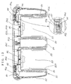
FIG. 11 is a front view of the calf massage unit 80 with
a cloth cover 82a partly removed to show the unit 80 partly
in section, FIG. 12 is a view in section taken along the line
X-X in FIG. 11, and FIG. 13 is a view in section taken along
the line Y-Y in FIG. 11.
With reference to FIGS. 1 and 2, the calf massage unit
80 has a pair of left and right leg-rests 83, 83 formed in a
resin cover 82 for the user to insert his or her calves thereinto.
A center wall 84 is disposed between the leg-rests 83, 83 to
provide these portions 83 on opposite sides thereof as shown
in FIGS. 1, 11 and 12. The cloth cover 82a covers the inner
surface of each leg-rest 83.
With reference to FIGS. 11 to 13, each leg-rest 83 is
provided on opposite side walls thereof with respective side
air bags 85, 85, and the inner surfaces of the bags are covered
with the cloth cover 82a. The side air bags 85, 85 are connected
together by a bellows connecting hose 85f and connected to the
common air supply hose 85a. The side air bags 85 are connected
to the pump 60 provided for the foot massage unit 10 by the
air supply hose 85a through a hose connector 85b (see FIG. 4)
extending through the lower end of the resin cover 82, the hose
connector 85c (see FIG. 4) provided on the rear wall of the
foot massage unit 10 and the solenoid valve 62 (see FIG. 9).
Although the side air bags 85, 85 are arranged
respectively on opposite side walls of the leg-rest 83, one
of the side bags can be made from an elastic member, for example,
of sponge, urethane or like material having elasticity.
An air bag 86 is disposed also on the bottom wall of the
leg-rest 83. The bottom air bag 86 can be, for example, the
one shown in FIG. 13 and provided with an acupressure projection
86a at the portion thereof to be brought into contact with the
calf of the user. Like the air bags 85 described above, the
bottom air bag 86 is also connected by an air supply hose 86b
to the pump 60 for the foot massage unit 10 through hose
connectors 86c, 86d and the solenoid valve 62. The acupressure
projection 86a can be formed integrally with the bottom air
bag 86 or attached to the bag 86 as by adhesion.
As shown in FIGS. 17 and 18, the hose connectors 85b,
86c extend downward and are bent rearward. Further as shown
in FIG. 4, the hose connectors 85b, 86c are arranged preferably
as shifted from the position of the hose connectors 85c, 86d
on the foot massage unit 10 so as not to be in register therewith
with respect to the vertical direction. When the hose
connectors are thus arranged, the air supply hoses 85a, 86b
interconnecting the hose connectors 85b, 85c and
interconnecting the hose connectors 86c, 86d, respectively,
can be made less likely to flex even when the calf massage unit
80 is tilted or slidingly moved relative to the foot massage
unit 10.
[Connecting Mechanism 90]
The calf massage unit 80 is coupled to the foot massage
unit 10 by the connecting mechanism 90.
With reference to FIGS. 1, 2, etc., the connecting
mechanism 90 can be composed of the tilting portions 91 (see
FIGS. 15 and 16) provided at opposite sides of the rear end
of the resin cover 12 of the foot massage unit 10, tilting rods
94, 94 (see FIGS. 13, 15 and 16) rotatably supported by the
tilting portions 91, sliders 99 arranged on the calf massage
unit 80 and supporting the upper ends of the respective
tilting rods 94 slidably and positionably in place as shown
in FIGS. 11 to 14, and a slide rail 97. The calf massage unit
80 is tiltable forward or rearward, slidable upward or downward
and positionable in place by the connecting mechanism 90
relative to the foot massage unit 10
With reference to FIGS. 2, 7, etc., the tilting portions
91 are arranged at opposite sides of the rear end of the resin
cover 12 of the foot massage unit 10. Each tilting portion
91 comprises a generally U-shaped screw mount 93 attached to
the resin cover 12 and a center pivot 92 secured to the mount
93 as shown in FIGS. 15 and 16. The tilting rod 94 has a base
end forwardly or rearwardly tiltably fitted around the center
pivot 92.
The tilting rod 94 has at its base end a mount plate 95
in the form of a generally elliptical flat plate, and is a metal
tube having a circular cross section and extending
continuously from the mount plate 95.
The mount plate 95 of the tilting rod 94 has a hole 95b
formed in its center and fitting around the center pivot 92
as shown in FIGS. 13, 15 and 16. The mount plate 95 has formed
in its peripheral surface a cutout 95a for an arm of the torsion
spring 98 to be described later to fit in.
The torsion spring 98 is fitted around the center pivot
92. The torsion spring 98 has one arm fitting in the cutout
95a in the mount plate 95 and the other arm fitting in a cutout
93a in the U-shaped screw mount 93 and secured to the center
pivot 92. The torsion spring 98 is adapted to bias the tilting
rod 94 toward the front.
The resin cover 12 has a surrounding portion 12b for
enclosing the tilting portion 91 therewith. According to the
illustrated embodiment, the resin cover 12 has a groove 12a
formed therein as shown in FIGS. 4, 7, 15 and 16 for permitting
the tilting rod 94 to be tilted from an upwardly extending
substantially vertically position rearward through a
specified angle, i.e., through about 90 degrees, to a fallen
position when the foot massage unit 10 is placed in a horizontal
position.
Because of the above construction, each tilting rod 94
is held in a substantially vertical upright position relative
to the foot massage unit 10 by the biasing force of the torsion
spring 98 when free from any load. When a rearward load is
applied to the tilting rod 94, the calf massage unit 80 tilts
rearward along with the tilting rod 94 [see FIGS. 6 and 16(a)].
When relieved of the load, the rod 14 returns the calf massage
unit 80 to the vertical position by virtue of the biasing force
of the torsion spring 98 [see FIGS. 5 and 16(b)].
The calf massage unit 80 is fitted to the upper ends of
the tilting rods 94, 94 slidably longitudinally of the rods
94 and positionably in place.
The tilting rods 94, 94 penetrate into the resin cover
82 of the calf massage unit 80 through holes 87, 87 formed in
opposite sides of the lower end of the resin cover 82.
The upper ends of the left and right tilting rods 94,
94 are interconnected by a mount plate 94a, which has mounted
thereon the sliders 99, 99 made of resin, positioned inwardly
of the respective tilting rods 94, 94 and each having a hard
ball 99a biased rearward by a spring 99b. As shown in FIGS.
11 to 14, the resin slider 99 is slidably fitted in the slide
rail 97 which is fastened with screws to a thick portion inside
the resin cover 82. A plurality of positioning holes 97a, 97a
are formed in the slide rail 97, as arranged longitudinally
of the rail at equal intervals (see FIG. 14).
When positioned in register with one of the positioning
holes 97a in the slide rail 97, the hard ball 99a fits into
the hole 97a by being biased by the spring 99b, preventing the
tilting rod 94 and the calf massage unit 80 from moving relative
to each other. Further when the user pulls up the unit 80 or
pushes down the unit, the ball 99a slips out of the positioning
hole 97a against the force of the spring 99b, rendering the
massage unit 80 movable upward or downward until the ball fits
into another lower or upper positioning hole 97a.
The calf massage unit 80 is coupled to the foot massage
unit 10 by the connecting mechanism 90 described, whereby the
massage unit 80 is made tiltable relative to the foot massage
unit 10 to move upward or downward and to be positioned in place
relative to the unit 10.
When the user as seated in a chair places his or her legs
into the leg massage unit 100, the calves bear on the bottom
walls of the leg-rests 83 of the calf massage unit 80 in a
substantially vertical position relative to the foot massage
unit 10 as shown in FIG. 5 and can be given a massage. Further
if the user lying on the floor places his or her legs into the
leg massage unit 100 with the knees drawn up, the calves force
the calf massage unit 80 rearward, allowing the user to be given
a massage, with the calf massage unit 80 rearwardly tilted
relative to the foot massage unit 10 as shown in FIG. 6.
Incidentally, the center of gravity of the foot massage unit
10 is positioned toward the front so that the foot massage unit
10 will not be positioned as raised off the floor even when
the calf massage unit 80 is tilted to the rearmost position.
When inserting the legs into the leg massage unit 100,
the user can move the calf massage unit 80 upward or downward
in conformity with the position of the calves. Further a
massage can be given to a wide range by moving the calf massage
unit 80 upward and downward.
The leg massage unit 100 can be manipulated in any mode
by using a control panel (not shown) provided at a suitable
location on the massage unit 100 or in the form of a remote
control. The massage unit 100 is controlled by control means
18 disposed inside the foot massage unit 10 (see FIGS. 9 and
10).
[Massage Operation]
The leg massage unit 100 of the construction described
above is used by the person to be massaged by placing his or
her feet into the recessed footrests 20 and his or her calves
into the leg-rests 83.
The user places the feet into the footrests 20 and presses
the heels against the upstanding walls 23. The feet of the
user are securely held in the footrests 20 by the upstanding
walls 23 and unlikely to move forward or rearward. Further
because the calf massage unit 80 is biased into contact with
the calves of the user by the springs 98, the calves are securely
held to the leg-rests 83.
In this state, the user can be massaged in various modes
by manipulating the control panel (not shown). An example of
massage operation will be described below.
When the power source of the leg massage unit 100 is
turned on by manipulating the control panel, the heaters 50
can be energized at the same time. The footrests 20 are heated
up before the user places his or her feet into the recessed
footrests 20. The footrests 20 are therefore unlikely to feel
cold when the feet are inserted into the footrests. The
heaters 50 may be so set that the passage of current
therethrough will be completed upon lapse of a predetermined
period of time (e.g., 15 minutes).
The user places his or her feet into the footrests 20
with the heaters 50 held in operation. For example when the
user desires to warm his or her feet which feel cold before
sleeping, the user may place the feet into the footrests with
the heaters 50 only energized, whereby the soles of the user
are warmed by a thermotherapeutic effect to result in improved
circulation of the blood.
[Massage by Foot Massage Unit 10]
Foot massages include, for example, an acupressure
massage by the acupressure rods 32 of the massage means 30,
a pressing massage by pressing the side parts of the feet from
the end of each foot to the ankle with the side air bags 21,
and a massage comprising the combination of these two modes
of massages.
The pressing massage can be given by inflating and
contracting the bottom air bag 34 and causing the acupressure
rods 32 to project from and retract into the bottom wall of
the recessed footrest 20. A highly effective acupressure
massage can be given to the sole, especially to the arch and
the base parts of the toes, by causing the acupressure rods
32 to project and retract, and moving the rods 32 to a desired
position or reciprocatingly moving the rods 32 (by applying
a rolling massage) in combination with this movement of the
rods 32. By warming the foot of the user with the heater 50
during the acupressure massage, a thermotherapeutic effect and
an acupressure therapeutic effect can be produced to give an
enhanced therapeutic effect.
The bottom air bag 34 can be inflated and contracted by
closing and opening the solenoid valve 62 and driving the pump
60. The acupressure rods 32 are movable forward and rearward
by diving the motor 47.
The control panel may be provided with buttons for
selecting different foot sizes for different users. This
enables the user to select his or her foot size to determine
the range of movement of the acupressure rods 32 in accordance
with the foot size for control when applying an acupressure
massage to the arch or the base parts of the toes. Indicated
at 29 in FIG. 7 are examples of contours of feet of users.
Since the acupressure massage pushes up the sole with
the acupressure rods 32, the user's foot will be raised off
the footrest 20. In giving the acupressure massage, therefore,
it is desirable to inflate the side air bags 21 to hold the
foot between the side air bags 21, 21 and thereby prevent the
foot from becoming raised.
The pressing massage is given by inflating and
contracting the side air bags 21 and thereby holding the side
parts of the foot from the end thereof to the ankle between
the side air bags 21, 21 to press the foot. The side air bags
21 can be inflated and contracted by closing and opening the
solenoid valve 62 and driving the pump 60.
The connecting hose 65 for supplying compressed air to
the side air bags 21 is in contact with the heater 50 and
therefore heats the compressed air to be supplied, whereby warm
air can be supplied to the side air bags 21. This gives a
thermotherapeutic effect also to the parts of the foot from
the end thereof to the ankle in addition to the
thermotherapeutic effect given to the sole by the heater 50.
The pressing massage produces the thermotherapeutic
effect and a pressure therapeutic effect to thereby give an
enhanced therapeutic effect.
When the acupressure massage and the pressing massage
are to be given in combination for massaging, the above
movements may be performed at the same time.
[Massage by Calf Massage Unit 80]
The calf can be massaged by an acupressure massage with
the projection 86a of the bottom air bag 86, and a pressing
massage with the side air bags 85, 85.
The acupressure massage can be given by inflating and
contracting the bottom air bag 86 and pressing the projection
86a against the calf. The bottom air bag 86 can be inflated
and contracted by closing and opening the solenoid valve 62
and driving the pump 60. A highly effective acupressure
massage can be given by holding the side air bag 85, 85 inflated
at this time since the user's calf is then unlikely to be pushed
out of the leg-rest 83. The calf massage unit 80 is biased
forward, i.e. , toward the calf, by the spring 98, so that even
if the calf is pushed forward by the projection 86a, the unit
80 follows this movement in intimate contact with the calf,
consequently eliminating the likelihood that the foot massage
unit 10 will be raised off the floor by the reaction exerted
by the calf.
The pressing massage is given by inflating and
contracting the side air bags 85, 85 and thereby holding the
calf between the side air bags 85, 85 to press the calf. The
side air bags 85 can be inflated and contracted by closing and
opening the solenoid valve 62 and driving the pump 60. The
pressing massage given to the calf results in improved
circulation of the blood.
When the acupressure massage and the pressing massage
are given in combination for massaging, the above operations
are performed at the same time.
The massage by the foot massage unit 10 and the massage
by the calf massage unit 80 may of course be given in
combination.
For example, the acupressure massage, pressing massage
and rolling massage by the foot massage unit 10, and the
acupressure massage and pressing massage by the calf massage
unit 80 can be given according to a suitably determined program.
In applying the rolling massage by the foot massage unit
10, smoothly varying acupressures are available by inflating
the bottom air bag 34 with the start of movement of the
acupressure rods 32 to cause the rods 32 to project
progressively, that is, by causing the acupressure rods 32 to
gradually project during the movement to obliquely press the
sole, continuing the movement after the rods are held projected
to a constant amount, and starting to conversely discharge the
air from the bottom air bag 34 upon the rods almost reaching
the position of completing the movement to progressively
retract the rods 32. The oblique pressing movement also gives
an acupressure massage resembling kneading, providing a
comfortable rolling massage. The same effect is available
also by the return movement of the acupressure rods 32.
Preferably, the leg massage unit is so set as to
automatically complete such various modes of massage upon
lapse of a predetermined period of time.
The massage means 30 are not limited to those of the above
embodiment but may comprise air bags only or means of the
vibration type.
Alternatively, the leg massage unit 100 may be disposed
at a low level in front of a chair for the user to sit in to
provide a massage machine of the chair type. When required,
a various massage means can be provided at a backrest, a seat
portion or the like of the chair.
The heater 50 may be provided not only on the bottom wall
of the recessed footrest 20 but also on the side wall thereof
as indicated in dotted lines in FIG. 10, or may be disposed
as bent so as to be in contact with both the bottom wall and
the side wall, whereby not only the sole but also side parts
of the foot can be warmed. Although the drawing shows the
heater 50a as provided on the rear side of the outer side wall
of the footrest 20, the heater 50a may be provided on the rear
side of the center side wall.
FIG. 19 shows hose connectors 85b, 86c according to a
different embodiment. The resin cover 82 has a recessed
portion 82b, in which hose connectors 85b, 86c facing downward
are arranged for joining thereto the air supply hoses 85a, 86b.
The recessed portion 82b thus provided serves to render the
air supply hoses 85a, 86b joined to the hose connectors 85b,
86c less likely to flex.
INDUSTRIAL APPLICABILITY
The leg massage unit of the invention comprises a calf
massage unit made tiltable and/or upwardly or downwardly
slidable, and is therefore useful for giving an enhanced
massage effect to the user.
Apparently, the present invention can be altered or
modified by one skilled in the art without departing from the
spirit of the invention. Such modification is included within
the scope of the invention as set forth in the appended claims.