EP1570817B1 - Beinprothese mit kniebremsfunktion - Google Patents
Beinprothese mit kniebremsfunktion Download PDFInfo
- Publication number
- EP1570817B1 EP1570817B1 EP03774049A EP03774049A EP1570817B1 EP 1570817 B1 EP1570817 B1 EP 1570817B1 EP 03774049 A EP03774049 A EP 03774049A EP 03774049 A EP03774049 A EP 03774049A EP 1570817 B1 EP1570817 B1 EP 1570817B1
- Authority
- EP
- European Patent Office
- Prior art keywords
- knee
- prosthetic limb
- joint
- brake circuit
- hydraulic brake
- Prior art date
- Legal status (The legal status is an assumption and is not a legal conclusion. Google has not performed a legal analysis and makes no representation as to the accuracy of the status listed.)
- Expired - Lifetime
Links
Images






Classifications
-
- A—HUMAN NECESSITIES
- A61—MEDICAL OR VETERINARY SCIENCE; HYGIENE
- A61F—FILTERS IMPLANTABLE INTO BLOOD VESSELS; PROSTHESES; DEVICES PROVIDING PATENCY TO, OR PREVENTING COLLAPSING OF, TUBULAR STRUCTURES OF THE BODY, e.g. STENTS; ORTHOPAEDIC, NURSING OR CONTRACEPTIVE DEVICES; FOMENTATION; TREATMENT OR PROTECTION OF EYES OR EARS; BANDAGES, DRESSINGS OR ABSORBENT PADS; FIRST-AID KITS
- A61F2/00—Filters implantable into blood vessels; Prostheses, i.e. artificial substitutes or replacements for parts of the body; Appliances for connecting them with the body; Devices providing patency to, or preventing collapsing of, tubular structures of the body, e.g. stents
- A61F2/50—Prostheses not implantable in the body
- A61F2/60—Artificial legs or feet or parts thereof
- A61F2/64—Knee joints
-
- A—HUMAN NECESSITIES
- A61—MEDICAL OR VETERINARY SCIENCE; HYGIENE
- A61F—FILTERS IMPLANTABLE INTO BLOOD VESSELS; PROSTHESES; DEVICES PROVIDING PATENCY TO, OR PREVENTING COLLAPSING OF, TUBULAR STRUCTURES OF THE BODY, e.g. STENTS; ORTHOPAEDIC, NURSING OR CONTRACEPTIVE DEVICES; FOMENTATION; TREATMENT OR PROTECTION OF EYES OR EARS; BANDAGES, DRESSINGS OR ABSORBENT PADS; FIRST-AID KITS
- A61F2/00—Filters implantable into blood vessels; Prostheses, i.e. artificial substitutes or replacements for parts of the body; Appliances for connecting them with the body; Devices providing patency to, or preventing collapsing of, tubular structures of the body, e.g. stents
- A61F2/50—Prostheses not implantable in the body
- A61F2/68—Operating or control means
- A61F2/70—Operating or control means electrical
-
- A—HUMAN NECESSITIES
- A61—MEDICAL OR VETERINARY SCIENCE; HYGIENE
- A61F—FILTERS IMPLANTABLE INTO BLOOD VESSELS; PROSTHESES; DEVICES PROVIDING PATENCY TO, OR PREVENTING COLLAPSING OF, TUBULAR STRUCTURES OF THE BODY, e.g. STENTS; ORTHOPAEDIC, NURSING OR CONTRACEPTIVE DEVICES; FOMENTATION; TREATMENT OR PROTECTION OF EYES OR EARS; BANDAGES, DRESSINGS OR ABSORBENT PADS; FIRST-AID KITS
- A61F2/00—Filters implantable into blood vessels; Prostheses, i.e. artificial substitutes or replacements for parts of the body; Appliances for connecting them with the body; Devices providing patency to, or preventing collapsing of, tubular structures of the body, e.g. stents
- A61F2/50—Prostheses not implantable in the body
- A61F2/60—Artificial legs or feet or parts thereof
- A61F2/64—Knee joints
- A61F2/642—Polycentric joints, without longitudinal rotation
- A61F2/644—Polycentric joints, without longitudinal rotation of the single-bar or multi-bar linkage type
-
- A—HUMAN NECESSITIES
- A61—MEDICAL OR VETERINARY SCIENCE; HYGIENE
- A61F—FILTERS IMPLANTABLE INTO BLOOD VESSELS; PROSTHESES; DEVICES PROVIDING PATENCY TO, OR PREVENTING COLLAPSING OF, TUBULAR STRUCTURES OF THE BODY, e.g. STENTS; ORTHOPAEDIC, NURSING OR CONTRACEPTIVE DEVICES; FOMENTATION; TREATMENT OR PROTECTION OF EYES OR EARS; BANDAGES, DRESSINGS OR ABSORBENT PADS; FIRST-AID KITS
- A61F2/00—Filters implantable into blood vessels; Prostheses, i.e. artificial substitutes or replacements for parts of the body; Appliances for connecting them with the body; Devices providing patency to, or preventing collapsing of, tubular structures of the body, e.g. stents
- A61F2/50—Prostheses not implantable in the body
- A61F2/68—Operating or control means
- A61F2/74—Operating or control means fluid, i.e. hydraulic or pneumatic
-
- A—HUMAN NECESSITIES
- A61—MEDICAL OR VETERINARY SCIENCE; HYGIENE
- A61F—FILTERS IMPLANTABLE INTO BLOOD VESSELS; PROSTHESES; DEVICES PROVIDING PATENCY TO, OR PREVENTING COLLAPSING OF, TUBULAR STRUCTURES OF THE BODY, e.g. STENTS; ORTHOPAEDIC, NURSING OR CONTRACEPTIVE DEVICES; FOMENTATION; TREATMENT OR PROTECTION OF EYES OR EARS; BANDAGES, DRESSINGS OR ABSORBENT PADS; FIRST-AID KITS
- A61F2/00—Filters implantable into blood vessels; Prostheses, i.e. artificial substitutes or replacements for parts of the body; Appliances for connecting them with the body; Devices providing patency to, or preventing collapsing of, tubular structures of the body, e.g. stents
- A61F2/50—Prostheses not implantable in the body
- A61F2/68—Operating or control means
- A61F2/74—Operating or control means fluid, i.e. hydraulic or pneumatic
- A61F2/744—Vane- or curved-cylinder type actuators, e.g. actuators using rotary pistons
-
- A—HUMAN NECESSITIES
- A61—MEDICAL OR VETERINARY SCIENCE; HYGIENE
- A61F—FILTERS IMPLANTABLE INTO BLOOD VESSELS; PROSTHESES; DEVICES PROVIDING PATENCY TO, OR PREVENTING COLLAPSING OF, TUBULAR STRUCTURES OF THE BODY, e.g. STENTS; ORTHOPAEDIC, NURSING OR CONTRACEPTIVE DEVICES; FOMENTATION; TREATMENT OR PROTECTION OF EYES OR EARS; BANDAGES, DRESSINGS OR ABSORBENT PADS; FIRST-AID KITS
- A61F2/00—Filters implantable into blood vessels; Prostheses, i.e. artificial substitutes or replacements for parts of the body; Appliances for connecting them with the body; Devices providing patency to, or preventing collapsing of, tubular structures of the body, e.g. stents
- A61F2/50—Prostheses not implantable in the body
- A61F2/68—Operating or control means
- A61F2/74—Operating or control means fluid, i.e. hydraulic or pneumatic
- A61F2/748—Valve systems
-
- A—HUMAN NECESSITIES
- A61—MEDICAL OR VETERINARY SCIENCE; HYGIENE
- A61F—FILTERS IMPLANTABLE INTO BLOOD VESSELS; PROSTHESES; DEVICES PROVIDING PATENCY TO, OR PREVENTING COLLAPSING OF, TUBULAR STRUCTURES OF THE BODY, e.g. STENTS; ORTHOPAEDIC, NURSING OR CONTRACEPTIVE DEVICES; FOMENTATION; TREATMENT OR PROTECTION OF EYES OR EARS; BANDAGES, DRESSINGS OR ABSORBENT PADS; FIRST-AID KITS
- A61F2/00—Filters implantable into blood vessels; Prostheses, i.e. artificial substitutes or replacements for parts of the body; Appliances for connecting them with the body; Devices providing patency to, or preventing collapsing of, tubular structures of the body, e.g. stents
- A61F2/50—Prostheses not implantable in the body
- A61F2/68—Operating or control means
- A61F2002/6818—Operating or control means for braking
-
- A—HUMAN NECESSITIES
- A61—MEDICAL OR VETERINARY SCIENCE; HYGIENE
- A61F—FILTERS IMPLANTABLE INTO BLOOD VESSELS; PROSTHESES; DEVICES PROVIDING PATENCY TO, OR PREVENTING COLLAPSING OF, TUBULAR STRUCTURES OF THE BODY, e.g. STENTS; ORTHOPAEDIC, NURSING OR CONTRACEPTIVE DEVICES; FOMENTATION; TREATMENT OR PROTECTION OF EYES OR EARS; BANDAGES, DRESSINGS OR ABSORBENT PADS; FIRST-AID KITS
- A61F2/00—Filters implantable into blood vessels; Prostheses, i.e. artificial substitutes or replacements for parts of the body; Appliances for connecting them with the body; Devices providing patency to, or preventing collapsing of, tubular structures of the body, e.g. stents
- A61F2/50—Prostheses not implantable in the body
- A61F2/68—Operating or control means
- A61F2002/6854—Operating or control means for locking or unlocking a joint
-
- A—HUMAN NECESSITIES
- A61—MEDICAL OR VETERINARY SCIENCE; HYGIENE
- A61F—FILTERS IMPLANTABLE INTO BLOOD VESSELS; PROSTHESES; DEVICES PROVIDING PATENCY TO, OR PREVENTING COLLAPSING OF, TUBULAR STRUCTURES OF THE BODY, e.g. STENTS; ORTHOPAEDIC, NURSING OR CONTRACEPTIVE DEVICES; FOMENTATION; TREATMENT OR PROTECTION OF EYES OR EARS; BANDAGES, DRESSINGS OR ABSORBENT PADS; FIRST-AID KITS
- A61F2/00—Filters implantable into blood vessels; Prostheses, i.e. artificial substitutes or replacements for parts of the body; Appliances for connecting them with the body; Devices providing patency to, or preventing collapsing of, tubular structures of the body, e.g. stents
- A61F2/50—Prostheses not implantable in the body
- A61F2/76—Means for assembling, fitting or testing prostheses, e.g. for measuring or balancing
- A61F2002/7615—Measuring means
- A61F2002/7655—Measuring means for measuring fluid pressure
Definitions
- This invention relates to a prosthetic limb including a knee joint which makes it possible for its user to bend the knee, the prosthetic limb flexibly braking the bending motion of the knee, i.e., a yielding prosthetic limb, and more particularly to a prosthetic limb in which a sensing part capable of detecting which part of the prosthetic limb, the load of its wearer is imposed on comprises a mechanical link mechanism.
- a flexible knee braking function namely, yielding function is a function for realizing the latter desire of those who need to wear a prosthetic limb. Owing to this yielding function, the knee joint is slowly changed in bending angle when the wearer's load is imposed on the prosthetic limb including a knee joint. Therefore, the wearer of the prosthetic limb having such a yielding function can smoothly walk down steps and a downhill by placing his/her weight on the prosthetic limb with confidence and moving the left and right limbs alternately.
- the yielding technique is a technique for flexibly locking the prosthetic limb in a bendable condition compared with a technique for completely locking the prosthetic limb (bending motion of the prosthetic limb).
- the technique for completely locking the prosthetic limb is a technique for producing a braking force by tightening a knee axis by utilizing a mechanical friction force, as shown, for example, in U.S, Patent No. 3,863,274 (corresponding to Japanese Patent Publication No. Sho 52-46432 ).
- the technique for flexibly locking the prosthetic limb is a technique for producing a braking force by utilizing a flow resistance generated when a working oil or fluid passes through a throttle.
- the flexible lock mechanism comprises a hydraulic brake circuit including several hydraulic equipments, besides the throttle.
- One of the hydraulic equipments included in the hydraulic brake circuit is means for defining two chambers into which or from which the working fluid flows.
- the means are a piston type including a reciprocally movable piston and a rotary type including a turnable vane.
- U.S. Patent No. 5,704,945 (corresponding to Japanese Patent Application Laid-Open No. H08-317944 ), U.S. Patent No. 2,667,644 , etc. disclose the rotary type, and U.S. Patent No. 2,530,286 , U.S. Patent No. 2,568,053 , etc. disclose the piston type.
- a hydraulic brake circuit normally includes a switch valve (i.e., control valve) for selectively switching between a braking position for producing a braking force with respect to the bending motion of the knee and a non-braking position for canceling the braking force.
- the hydraulic brake circuit i.e., switch valve for the hydraulic brake circuit
- sensing control means for controlling the hydraulic brake circuit in such a manner it is accepted that a walking mode of the wearer is detected by an electric sensor such as a strain gage and a control signal is outputted from a microcomputer in accordance with the detection signal.
- controlling can also be made totally in such a manner as to detect and process electrically or electronically,
- data processing since data processing must be done using a microcomputer for that purpose, it is necessary to prepare a power source for it, Moreover, the electric sensor must be maintained always in a detectable condition. This means to consume electric power to that extent.
- the sensing control means is constituted mechanically.
- the conventional technique adopting a mechanical method has the following problem. Since it is not of the type capable of detecting which part of the foot the load of the wearer is imposed on, braking force is not correctly canceled at the time for departing the toe in the final stage of the stance phase in case the wearer tries to walk down steps or downhill. This makes it difficult for the wearer to smoothly shift the walking phase into the swing phase.
- the reasons are as follows. When the wearer walks down steps or downhill, he/her tends to place the center of gravity comparatively backward. Therefore, the floor reaction force passes through a rather rear part of the knee axis.
- the switch valve of the hydraulic brake circuit can be switched effectively in such a manner as to interlock to the motion of the foot or motion in association with the bending motion of the knee, In contrast, in case the wearer walks down steps or downhill, it is almost impossible for him/her to make such a switching operation correctly due to the attitude of the wearer.
- an object of the present invention to provide a prosthetic limb having a flexible braking function, which is capable of mechanically detecting which part of the foot the load of the wearer is imposed on.
- Another object of the present invention is to provide a prosthetic limb having a flexible braking function, which is capable of correctly canceling braking force at the time the toe is departed from the floor in the last stage of the stance phase.
- a further object of the present invention is to provide a prosthetic limb having a flexible braking function, which can be applied not only to a prosthetic limb having a single axis but also to a prosthetic limb having a multi-axis.
- a still further object of the present invention is to provide a prosthetic limb, which is capable of positively producing a desired braking force when a predetermined load is imposed, in order to ensure safety of the flexible knee braking function.
- a yet further object of the present invention is to provide a prosthetic limb, in which the flexible knee braking function in a stance phase and controlling in a swing phase are compatible.
- An additional object of the present invention is to provide a prosthetic limb, in which the wearer can impose the load on the knee with a confidence and the knee can be bent by his/her own will.
- a prosthetic limb including a foot, a knee joint, a joint upper member located above said knee joint and a joint lower member located below said knee joint and both the upper and lower members being pivotally connected to one another about said knee joint such that the limb can be bent about said knee joint;
- said lower member includes a component which comprises part of said knee joint and a main body part connected to said component and which moves only slightly in comparison with the bending motion of the limb, wherein said limb has a hydraulic brake circuit for producing a braking force with respect to the bending motion of the limb by flow resistance generated by throttling a fluid passing through a throttle characterized in that there is also provided a sensing control means to detect which part of the foot is bearing the weight of a wearer and controlling said hydraulic brake circuit in accordance with this so as to control the braking motion of the limb wherein said sensing control means comprises a link mechanism for connecting said component and said main body part to each other in said lower member, said link mechanism having an instantaneous
- the hydraulic brake circuit includes, in addition to the throttle and the check valve, means for defining two chambers into which or from which working fluid flows, and a switch valve capable of switching between a braking position and a non-braking position.
- means for defining two chambers there are two types, as already mentioned above, one being a piston type including a reciprocally movable piston and the other being a rotary type including a turnable vane. Any of those two types can be applied to the present invention.
- the rotary type is more preferable. Owing to the hydraulic brake circuit, there can be obtained not only the flexible knee braking function in the stance phase but also the controlling of the bending motion of the knee in the swing phase.
- the switch valve is a valve which is opened/closed upon receipt of load of the wearer, and it performs a switching function in which switching is made between an open position and a closed position.
- the switch valve in the closed position shuts off the flow of the working fluid to make it effective of the throttling function, and the switch valve in the open position allows the working fluid smoothly to make it meaningless or ineffective of the throttling function.
- a switch valve a switch which has such a structure that the valve can be switched between an open position and a closed position by a small number of strokes.
- a particularly preferable valve is a seat valve in which a valve body is urged against a valve seat to open/close the valve.
- the valve body In the seat valve, the valve body is moved in the orthogonal direction with respect to the plane of the valve seat at the time the valve is opened/closed.
- a ring-shaped opening having a height equal to that movement is formed. Accordingly, a large area of a flow passageway can instantaneously be obtained.
- the valve body and the valve seat of the switch valve are surface contacted with each other in order to reliably and rapidly perform the switching operation of the switch valve.
- This invention can widely be applied to a prosthetic limb comprising a joint upper member located at an upper side of the knee, and a joint lower member located at a lower side of the knee and pivotably connected to the joint upper member so that the knee can be bent.
- a prosthetic limb comprising a joint upper member located at an upper side of the knee, and a joint lower member located at a lower side of the knee and pivotably connected to the joint upper member so that the knee can be bent.
- As means for pivotably connecting the joint upper member and the joint lower member together there are known means for connection by means of a single-axis or by means of a multi-axis using plural axes such as four axes.
- the present invention can be applied to any one of them. Since this invention intends to obtain a flexible knee braking function chiefly by mechanical means, the joint lower member of the prosthetic limb comprises two parts which can be moved relative to each other.
- the joint lower member comprises a joint component part composing the knee joint which is connected to the joint upper member such that the knee can be bent, and a main body part connected to the lower side of the joint component part and moving only slightly, when compared with the motion of the knee, with respect to the joint component part.
- the joint component part is located at an upper part of the main body part, and a foot is located at a lower part of the main body part.
- the hydraulic brake circuit is disposed at the joint component part of the joint lower member, and a rotary type means including a turnable vane is employed as means for defining two chambers in the hydraulic brake circuit.
- This invention further comprises a specific sensing control means for detecting, in order to control the hydraulic brake circuit for producing a braking force with respect to the bending motion of the knee, which part of the foot the load of the wearer is imposed on and control the hydraulic brake circuit in accordance with the detection signal.
- the sensing control means has the following constitutional features y1 and y2,
- the sensing control means includes a sensing part for detecting which part of the foot the load of the wearer is imposed on, and a control part for controlling the hydraulic brake circuit in accordance with the detection signal coming from the sensing part.
- the sensing part comprises the above-mentioned predetermined link mechanism, and the instantaneous center of the link mechanism serves as a sensing point.
- the following detection signal z1 or z2 is generated,
- the mechanical link mechanism produces mutually different two rotational moments, one being folded forward about the instantaneous center and the other being folded backward. Those mutually different rotational moments serve as detection signal detected by the link mechanism.
- the hydraulic brake circuit is controllingly switched between a braking position and a non-braking position.
- This controllingly switching operation generally refers to a controllingly opening/closing operation to be made with respect to the switch valve in accordance with motion of one link of the link mechanism. It should be noted, however, that the controllingly switching operation is not limited to the above.
- an electric switch is switched in accordance with the motion of a link of the link mechanism and the throttling amount of the variable throttle is controlled by a motor or the like in accordance with the switching action.
- detection made by the sensing part is the mechanical
- controlling of the hydraulic brake circuit by a control part is not limited to the mechanical. Instead, it may include the electric or electronic.
- the mechanical link mechanism has an instantaneous center between the toe and the heel of the foot of the prosthetic limb.
- the instantaneous center is preferably in a region below the link mechanism and at a forward region from a loading line passing through the center of gravity of the wearer in a standing position. If the instantaneous center is in the above-mentioned region, the braking force can surely be produced in a standing position and the braking force can effectively be canceled at the time the toe is departed from the floor on a downhill. Thus, there can be obtained a prosthetic limb of high stability.
- the switch valve of the hydraulic brake circuit may be either of the normally open type or of the normally closed type. In view of surely preventing the knee from folding by reliably applying a braking function at normal times, however, the normal closed type is preferable. Moreover, in case controlling in the swing phase is made by an air cylinder apparatus other than the hydraulic brake circuit, it is preferable that the switch valve is normally closed and the instantaneous center of the link mechanism is located at a relatively lower part in the vicinity of the foot. By doing so, the force acting for opening the switch valve is increased due to force of inertia of the prosthetic limb caused by the swinging out action even after the toe is departed from the floor and the walking phase is shifted into the swing phase.
- a reaction force of the air cylinder apparatus is additionally applied.
- the switch valve can be opened and controlling in the swing phase can be executed smoothly.
- a spring force for applying a sitting force to the valve body so as to sit on the valve seat can be invalidated when the prosthetic limb is contacted to the floor at the toe, for example.
- the switch valve and the throttle are composed of a valve apparatus which is placed at an intermediate part of the passageway. This arrangement may be employed into the present invention. In view of surely exhibiting the flexible knee braking function, however, it is preferable that the switch valve and the throttle are separated and connected to a check valve in parallel.
- the switch valve can surely be switched when a predetermined load is applied to the prosthetic limb irrespective of the size and direction of the load. This makes it possible to stably produce a predetermined braking force. Accordingly, the wearer can freely control the knee braking force in the way he/or she wants.
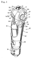
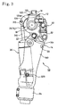
- FIGS. 1 through 3 illustrate an overall construction of a thigh prosthesis 10 to which the present invention is applied.
- a thigh prosthesis 10 and the features of the present invention contained therein will be described with reference to those Figures.
- the thigh prosthesis 10 is a prosthetic limb for those who have no knee.
- This thigh prosthesis 10 includes a joint upper member 12 located at an upper side of the knee and a joint lower member 14 located at lower side of the knee and pivotably connected to the joint upper member 12 so that the knee can be bent.
- a main component of the joint upper member 12 is a knee plate 120 which is made of aluminum alloy.
- the knee plate 120 is provided with a part 122 located at an upper part thereof and adapted to support an alignment block 16, a pair of arms 124a, 124b located at left and right sides thereof and adapted to support a knee axis, and a third arm 126 located between the arms 124a, 124b.
- the alignment block 16 is made of, for example, titanium alloy and fixedly screwed to the knee plate 120.
- the alignment block 16 supports a socket, not shown, and bears the wearer's load through the thigh which is inserted in the socket.
- the knee axis (not shown) is integrally fixed to the knee plate 120 (thus, to the joint upper member 12) by toothed check bolts 18 which are bolted into opposite sides of the knee plate 120.
- the thigh prosthesis 10 is a single-axis prosthetic limb which has a single (only one) knee axis.
- the joint upper member 12 and the joint lower member 14 are rotatable about the single knee axis.
- the joint lower member 14 is provided with a hollow frame 140 which is made of carbon fiber-reinforced plastic, and some other component members such as a base bracket 22 which is fixed to an upper part of the frame 140 by a plurality of check bolts 20 and a housing member 24 which is rotatably connected to the knee axis and further connected to the base bracket 22 through a specific link mechanism (later described).
- the base bracket 22 and the housing member 24 are each made of aluminum alloy.
- the housing member 24, which is rotatably about the knee axis, is a joint component part which composes a knee joint through which the knee can be bent.
- the housing member 24 as a joint component part can be rotated or pivoted at such a large angle as, for example, 150 degrees to 160 degrees with respect to the joint upper member 12 including the knee plate 120.
- the housing member 24 is also a part composing a hydraulic brake circuit which produces a braking force with respect to the bending motion of the knee.
- the housing member 24 comprises a main body 240 having cylinder holes formed in opposite sides and for defining an internal space for retaining hydraulic, and closing cover members 242 located at opposite sides of the main body 240 and for closing the opening of the cylinder hole.
- the hydraulic brake circuit in the housing member 24 is to obtain a knee braking function (controlling in a stance phase) related to the present invention.
- the thigh prosthesis 10 further includes an air cylinder unit 30 operated by pneumatic.
- This air cylinder unit 30 serves as walking auxiliary means in a swing phase.
- This air cylinder unit 30 itself is known per se. For example, it is of the same type as those which are disclosed in U.S. Pat. No. 5,405,407 , Japanese Patent Application Laid-Open Publication No. H09-551 , U.S. Pat. No. 5,888,237 or the like.
- the thigh prosthesis 10 is a prosthetic limb which is capable of achieving the controlling by hydraulic in the stance phase and by pneumatic in the swing phase.
- the air cylinder unit 30 is rotatably supported at one end thereof on the rod 310 side by the arm 126 through a clevis pin 312 and at another end on the cylinder bottom side by a trunnion pin 320 which is fixed to the frame 140.
- a sectionally C-type ring-shaped tightening member 34 which is located at a lower part of the frame 140 is adapted to connect a foot pipe to the frame 140. A lower end of the foot pipe is, of course, attached with a foot-shaped foot.
- a joint component part 14j (housing member 24) of the joint lower side member 14 and a main body part 14b (part including the frame 140 and a base bracket 22 which is integral with the frame 140) which is located at a lower part of the joint component part are connected to each other by a specific link mechanism 50.
- the link mechanism 50 allows a small relative motion between the housing member 24 as a joint component part and the base bracket 22 on the main body part.
- the link mechanism 50 has an instantaneous center between the toe and the heel of the foot of the thigh prosthesis 10.
- small motion refers to a very small pivoting motion at an angle of 3 degrees or less, for example.
- the link mechanism 50 is a mechanical construction and it has an instantaneous center outside the component element thereof.
- the instantaneous center serves as a sensing point which makes it possible to distinguish between a case in which the load of the wearer is imposed on the heel of the foot and another case in which the load of the wearer is imposed on the toe. Based on the detection result, the link mechanism 50 controls the hydraulic brake circuit.
- the instantaneous center located at a predetermined region outside the link mechanism 50 which composes the sensing part. Owing to this feature, correct detection can always be obtained irrespective of the walking attitude of the wearer, not only at the time the wearer is walking on a flat land but also at the time the wearer is walking down steps and a downhill. And based on this detection, the hydraulic brake circuit can properly be controlled and a flexible knee braking function can be obtained.
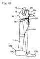
- FIGS. 4A and 4B show the link mechanism 50 in the form of a skeleton.
- FIG. 4A is an example in which a bar link is used
- FIG. 4B is another example in which a part of the bar link is replaced with a slide. Both of them are equivalent as a link mechanism.
- the knee axis 15 rotatably interconnect the joint upper member 12 and the joint lower member 14.
- a foot 172 is attached to a lower part of the joint lower member 14 through a foot pipe 170.
- a front link 52 and a rear link 54 are pivotally connected between the joint component part 14j and a main body part 14b of the joint lower member 14. Owing to this arrangement, the link mechanism 50 of FIG.
- FIG. 4A comprises, besides the joint component part 14j and the main body part 14b, the front link 52 and the rear link 54.
- a mechanically equivalent slide 56 is used instead of the rear link 54.
- Those link mechanisms 50 have an instantaneous center at a point O between the toe 172t and the heel 172h of the foot 172.
- the front link 52 of the link mechanism 50 serves as a pivot connection part A at an intermediate part thereof in the axial direction with respect to the joint component part 14j side.
- a part 52e at an end of the link from the pivot connection part A serves as an operating element of the switch valve 60 of the hydraulic brake circuit.
- a spring 58 composed of a compression spring is disposed at the opposite side to the part 52e of the front link 52 in order to normally close the switch valve 60.
- FIGS. 5A and 5B show the action of the link mechanism 50.
- the link mechanism 50 is a quadratic link mechanism having a pivot joint part at four points A, B, C and D.
- the instantaneous center O of the link mechanism 50 is an intersection between a straight line connecting the pivot joint part A and B of the front link 52 and a straight line connecting the pivot joint part C and D of the rear link 4.
- force of the spring 58 acts on the front link 52.
- an operating force f acts on the switch valve 60 so that the switch valve 60 is closed to bring the prosthetic limb into a state in which the prosthetic limb is subjected to braking operation of the hydraulic brake circuit (see FIG. 5A ).
- the floor reaction F acts on the heel 172h or heel 172h side of the foot 172, the floor reaction force F acts backward of the instantaneous center O.
- the link mechanism 50 is deformed such that the operating force f acts on the switch valve 60 as in the normal state (see FIG. 5B , link mechanism AB' CD' after deformed),
- the floor reaction force F acts on the toe 172t or toe 172t side of the foot 172
- the floor reaction force F acts forward of the instantaneous center O.
- the link mechanism 50 is deformed such that the force of the spring 58 is offset to open the switch valve 60 so that the braking effect of the hydraulic brake circuit is canceled (see FIG. 5C , link mechanism AB" CD" after deformed).
- the thigh prosthetic limb 10 as shown in FIG. 6 , comprises a hydraulic brake circuit 70 including the switch valve 60 and an air cylinder apparatus 30 including an air cylinder 30a and a pneumatic circuit 30c attached thereto.
- the prosthetic limb 10 including a combination circuit of the hydraulic and pneumatic can obtain a flexible knee braking function in the stance phase owing to the hydraulic brake circuit 70, and an auxiliary function of the bending motion and the extending motion of the knee in the swing phase owing to the air cylinder apparatus 30.
- a piston contained therein defines two chambers, one at the front side and the other at the rear side, in the axial direction of the piston.
- the pneumatic circuit 30c includes a throttle and a check valve and controls the flow of air flowing into and out of the front and rear chambers.
- the chamber defining means (i.e., air cylinder 30a) in the air cylinder apparatus 30 is of a piston type in which the piston is reciprocally moved in the axial direction.
- a chamber defining means 80 in the hydraulic brake circuit 70 is of a rotary type in which a turnable vane 82 defines two chambers 80e and 80f.
- the turnable vane 82 on the hydraulic brake circuit 70 side and the piston 30a on the air cylinder apparatus 30 side are connected to each other through the knee plate 12.
- the first chamber 80e is an extending chamber and the second chamber 80f is a bending chamber.
- the extending chamber 80e is a chamber into which oil flows when the knee extends and out of which oil flows when the knee bends.
- the bending chamber 80f is a chamber into which oil flows when the knee bends and out of which oil flows when the knee extends.
- the extending chamber 80e is communicated with one side of the switch valve 60 through a first passageway 250, and the bending chamber 80f is communicated with the other side of the switch valve 60 through a second passageway 260.
- the first passageway 250 or the second passageway 260 may be provided with an accumulator.
- the hydraulic brake circuit 70 further includes a check valve 92 and a throttle (i.e., throttle valve) 94 in parallel with the switch valve 60 and the chamber defining means 80 between the first passageway 250 and the second passageway 260.
- the check valve 92 is a one-way valve for prohibiting the flow from the first passageway 250 side toward the second passageway 260 side (i.e., flow from the first chamber 80e toward the second chamber 80f) and allowing the flow in the opposite direction.
- the throttle 94 is a member for applying resistance to the flow passing therethrough. As this throttle 94, various types can be employed. Among them, those are preferable in which the throttling amount can easily be adjusted depending on the physical features, preference of the manner of walking of the wearer, etc..
- the throttle 94 there can be listed a throttle in which axially slanted cutout grooves (for example, two cutout grooves are arranged in the peripheral direction at an interval of 180 degrees) are formed in the outer periphery of the valve body.
- the throttle 94 thus constructed can easily be adjusted in its throttling amount by screw adjustment so that it can appropriately be met with the characteristic of the wearer.
- any of the normally open and the normally closed type can be applied to the switch valve 60.
- the normally closed switch valve 60 is employed.
- the braking function caused by the throttle 94 can always work efficiently at normal times so that the knee can be prevented from being folded.
- the flow resistance caused by the throttle 94 is equivalent to, for example, 40 to 100 Nm and the wearer of the prosthetic limb equipped with the knee brake circuit 70 can slowly bend the knee by placing his/her weight onto the knee.
- the knee brake circuit 70 is designed such that a braking force is produced by the flow resistance caused by throttle 94 which is provided separately from the switch valve 60, the wearer can surely and rapidly execute the opening/closing controlling operation of the switch valve 60 by placing his/her own weight onto the prosthetic limb.
- the reason why is as follows, In the switch valve 60, when a predetermined load is imposed on the prosthetic limb, a plunger 610 is actuated, and slight movement of the plunger 610 generates a ring-like large opening.
- the switch valve 60 keeps its closed state when the walking phase is shifted from the swing phase into the stance phase, Accordingly, in the hydraulic brake circuit 70, the throttle 94 is effectively operated to provide a flexible knee bending function, i.e., to exhibit a yielding function. And in the stance phase, when the floor reaction force of the wearer is located at the front side of the instantaneous center O of the link mechanism 50 (i.e., when the floor reaction force is shifted to the toe 172t side), the switch valve 60 is surely switched into the open position under the effect of the link mechanism 50. Accordingly, the hydraulic brake circuit 70 does not produce any unnecessary braking force to the knee bending operation and the wearer can smoothly depart the toe of the foot from the floor.
- the switch valve 60 is of a normal closed type, it is brought into the open position by force of inertia caused by swinging out motion of the prosthetic limb 10 in the swing phase. For this reason, the hydraulic brake circuit 70 is not interfered with the controlling operation made by the air cylinder apparatus 30 in the swing phase, in spite of the fact that the switch valve 70 is of a normal closed type.
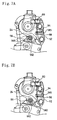
- FIGS. 7A and 7B and FIG. 8 are useful in knowing the relation of arrangement of various component elements of the hydraulic brake circuit 70.
- FIGS. 7A and 7B show the construction of an upper part of the thigh prosthetic limb 10, especially a part surrounding the knee axis.
- FIG. 7A shows a closed state (i.e., normal state and a state in which the heel 172h side of the foot is contacted with the floor) of the switch valve 60, and FIG.
- the front link of the link mechanism 50 is a bar link (front link 52), while the rear link is a slide 56.
- the slide 56 comprises a guide hole 560 formed in the main body 240 of the housing member 24 and a guide rod 562 guided by the guide hole 560.
- the guide rod 562 is fixed to the base bracket 22. Accordingly, the housing member 24 having the guide hole 560 and the base bracket 22 integral with the frame 140 can relatively slightly be moved by the link mechanism 50.
- the amount of the movement is sufficient for switching the switch valve 60 from the closed position to the open position or in the reversed way. For example, the amount of the movement is a stroke equal to several mm or less, or a pivotal angle equal to several degrees or less.
- FIG. 8 is a view in which a cover member 242 of the housing member 24 is removed and the main body 240 part of the housing member 24 is viewed from the axial direction of the knee axis.
- the turnable vane 82 is integrally supported by the knee axis 15 which is fixed to the knee axis support arms 124a, 124b of the knee plate 120.
- the turnable vane 82 partitions the inside space of the main body 240 into the first chamber (high pressure chamber or extending chamber) 80e and the second chamber (low pressure chamber or bending chamber) 80f.
- the main body 240 of the housing member 24 receives therein the switch valve 60, a throttle valve as the throttle 94 and the check valve 92.
- a receiving part of the switch valve 60 is located at an upper part of the main body 240 and a receiving part of the throttle valve 94 is located at a lower part thereof.
- a receiving part of the check valve 92 is located at an inner part of the receiving part of the throttle valve 94.
- the receiving parts of the switch valve 60 and the throttle valve 94 extend toward the inside of the main body from one surface of the main body 240 which faces the front link 52.
- the receiving part of the check valve 92 extends in a direction parallel to the axial direction of the knee axis 15, Moreover, a passageway of the hydraulic brake circuit 70 is also formed in the main body 240 of the housing member 24.
- FIG. 9 is a sectional view showing the switch valve 60 received in the main body 240 of the housing member 24.
- the main body 240 is provided with the first passageway 250 on the high pressure side, the second passageway 260 on the low pressure side and a receiving hole 246 which is communicated with the first and second passageways 250, 260.
- the switch valve 60 is adapted to intercommunicate or cutoff the communication between the first passageway 250 side and the second passageway 260 side.
- a main body of the switch valve 60 is a small-sized plunger 610 which is movably fitted to the interior of the receiving hole 246.
- the plunger 610 is sealed liquid tight by a seal member 620 located at an outer periphery thereof and subjected to force directing outward of the receiving hole 246 which force is produced by a valve spring 630. However, the plunger 610 is also subjected at one end 610a, which projects from the receiving hole 246, to force produced by the spring 58 through the front link 52. In order for the force of the spring 58 to overcome the force of the valve spring 630, in a normal condition, a distal end 610b of the plunger 610 is abutted with a valve seat on the main body 240 side, thereby maintaining the switch valve 60 in the closed position.
- the link mechanism 50 detects that the toe 172t has contacted with the floor, the force of the spring 58 acting through the front link 52 is canceled and therefore, the plunger 610 is caused to move outward of the receiving hole 246 by the force of the valve spring 630 to bring the switch valve 60 into the open position.
- the switch valve 60 produces a ring-like large opening in response to slight movement of the plunger 610, it is switched from the closed position to the open position or from the open position to the closed position rapidly and surely.
- One end of the spring 58 is retained by the main body 240 of the housing 24 and the other end is retained by a threaded member 585 which is threadingly engaged with the front link 52. Accordingly, by varying the threading amount of the threaded member 585, the force of the spring 58 can be adjusted (see FIGS. 7A and 7B ).
- FIG. 10 is a sectional view showing the check valve 92 and the throttle valve 94 receiving in the housing member 24.
- the check valve 92 and the throttle valve 94 are arranged in such a manner as to be orthogonal to each other within the housing member 24.
- a receiving hole 2492 of the check valve 92 laterally pierces through the main body 240 of the housing member 24, and opposite sides of the receiving hole 2492 are closed by cover members 242.
- the receiving hole 2492 is provided at an intermediate part thereof in the axial direction with an inner wall part 92s which serves as a valve seat of the check valve 92.
- the check valve 92 includes, in addition to the valve seat 92s, a ball valve body 922 sitting on the valve seat 92s and a valve spring 924 for exerting a sitting force to the ball valve body 922.
- a receiving hole 2494 of the throttle valve 94 diagonally extends through the main body 240 of the housing member 24 and an opening at one end thereof is faced forwardly of the prosthetic limb 10.
- a main body of the throttle valve 94 is a plunger valve body 942 inserted in the receiving hole 2494.
- the plunger valve body 942 is provided with cutout grooves 942t (two cutout grooves arranged at an interval of 180 degrees in the peripheral direction and slanted in the axial direction) formed in an outer periphery on one side thereof in the axial direction. Those two cutout grooves 942t with the help of the wall surface of the main body 240 of the housing member 24 produces a flow resistance. That side of the plunger valve body 942 where the cutout groove 942t is formed is located at an inner part of the receiving hole 2494, and an end part 942a on the opposite side is supported by the threaded member 96.
- the throttling amount of the throttle valve 94 can be adjusted.
- the distal end side of the plunger 92 of the throttle valve 94 where the cutout groove 942t is formed is communicated with the high pressure side of the check valve 92.
- An outer periphery of each cutout groove 942t is communicated with the low pressure side of the check valve 92. Those communications are achieved by a passageway formed in the main body 240 of the housing member 24.
- the throttle valve 94 is demanded to be adjustable in throttling amount after the prosthetic limb 10 is assembled, while there is no such demand for the check valve 92.
- the check valve 92 may be disposed within the turnable vane 82 instead of within the housing member 24.
- the turnable vane 82 is integral with the knee axis 15 and executes such a large turning motion as 150 degrees to 160 degrees which are same as the turning angles of the knee joint.
- the range capable of producing a braking force for the yielding function is only in the range from an extended state of the knee to a bent state achieved by bending the knee at an angle of approximately 90 degrees.
- the braking force produced by the hydraulic brake circuit 70 is basically not required.
- the turnable vane 82 can turn smoothly irrespective of the opening/closing operation of the switch valve 60.
- a passageway for restraining the production of unnecessary braking force is formed in the main body 240 of the housing member 24.
- FIG. 11 shows another example, in which the control element of the switch valve 60 is disposed on the rear link 54 side instead of on the front link 52 side.
- the rear link 54 includes a link part 54e serving as an operating element which is disposed at a pivot joint part P with respect to the housing member 24 which serves as the joint component part 14j.
- FIGS. 12 and 13 show examples in which the present invention is applied to a prosthetic limb equipped with a quadratic link mechanism 515 composing the knee joint.
- one pivot joint part P' in the link mechanism 515 is braked.
- a rod 40 is connected to the link mechanism 515 and motion of the link mechanism 515 is braked through the rod 40.
- FIG. 14 shows a combination circuit in which hydraulic component elements are combined with the knee brake circuit 70 operated by hydraulic and including a switch valve 60.
- the newly employed component elements which are to be combined with the knee brake circuit 70 are an extending auxiliary circuit 101 including a throttle valve 410 and a check valve 510, and a bending auxiliary circuit 102 including a throttle 420 and a check valve 520.
- the knee brake circuit 70 is adapted to obtain a flexible knee braking function in a stance phase of the prosthetic limb, while the extending auxiliary circuit 101 and the bending auxiliary circuit 102 are adapted to obtain a flexible knee braking function in a swing phase of the prosthetic limb.
- the throttles 410, 420 in the extending auxiliary circuit 101 and the bending auxiliary circuit 102 are small in throttling amount compared with the throttle 40 of the knee brake circuit 70.
- the flow resistance caused by those throttles 410, 420 is a value corresponding to a bending resistance and 8 Nm at the maximum.
- the check valves 510, 520 in the extending auxiliary circuit 101 and the bending auxiliary circuit 102 are, of course, one-way valves which allow only the mutually reversed flows.
- the hydraulic circuit can be built in a knee part of the prosthetic limb. This makes it possible to design the prosthetic limb smaller in size.
Landscapes
- Health & Medical Sciences (AREA)
- Transplantation (AREA)
- Life Sciences & Earth Sciences (AREA)
- Animal Behavior & Ethology (AREA)
- Engineering & Computer Science (AREA)
- Biomedical Technology (AREA)
- Heart & Thoracic Surgery (AREA)
- Vascular Medicine (AREA)
- Cardiology (AREA)
- Oral & Maxillofacial Surgery (AREA)
- General Health & Medical Sciences (AREA)
- Public Health (AREA)
- Veterinary Medicine (AREA)
- Orthopedic Medicine & Surgery (AREA)
- Prostheses (AREA)
- Professional, Industrial, Or Sporting Protective Garments (AREA)
- Braking Arrangements (AREA)
- Orthopedics, Nursing, And Contraception (AREA)
Claims (14)
- Prothetische Gliedmaße (10), die Folgendes einschließt: einen Fuß (172), ein Kniegelenk (120, 122, 16, 124a, 124b), wobei ein oberes Gelenkelement (12) oberhalb des Kniegelenks angeordnet ist und ein unteres Gelenkelement (14) unterhalb des Kniegelenks angeordnet ist und das obere und das untere Element beide um das Kniegelenk schwenkbar miteinander verbunden sind derart, dass die Gliedmaße um das Kniegelenk gebeugt werden kann, wobei das untere Element (14) einen Bestandteil, der einen Teil des Kniegelenks umfasst, und einen Hauptkörperteil (22), der mit dem Bestandteil verbunden ist und der sich im Vergleich mit der Beugebewegung der Gliedmaße nur geringfügig bewegt, einschließt, wobei die Gliedmaße einen hydraulischen Bremskreis (70) hat, um durch einen Durchflusswiderstand, erzeugt durch Drosseln eines Fluids, das durch eine Drossel (94) hindurchgeht, eine Bremskraft in Bezug auf die Beugebewegung der Gliedmaße zu erzeugen, dadurch gekennzeichnet, dass ebenfalls ein Sensorsteuerungsmittel (50, 52, 54, 56) bereitgestellt wird, um zu erfassen, welcher Teil des Fußes das Gewicht eines Trägers trägt, und den hydraulischen Bremskreis (70) in Übereinstimmung damit zu steuern, um so die Bremsbewegung der Gliedmaße zu steuern, wobei das Sensorsteuerungsmittel einen Verknüpfungsmechanismus (50) umfasst, um den Bestandteil und den Hauptkörperteil in dem unteren Element miteinander zu verbinden, wobei der Verknüpfungsmechanismus einen Augenblickspol zwischen der Zehe und der Ferse des Fußes hat und die Bewegung in dem Verknüpfungsmechanismus erfasst wird und die Steuerung des hydraulischen Bremskreises auf die folgende Weise erreicht wird:z1. wenn die Ferse des Fußes der prothetischen Gliedmaße in Berührung mit dem Fußboden gebracht wird, geht eine Fußbodenreaktionskraft, verursacht durch die Grundberührung der Ferse, durch die Rückseite des Augenblickpols des Verknüpfungsmechanismus, was ein Drehmoment für das untere Gelenkelement in einer Vorwärtsfaltrichtung um den Augenblickspol erzeugt,z2. wenn die Zehe des Fußes der prothetischen Gliedmaße in Berührung mit dem Fußboden gebracht wird, geht eine Fußbodenreaktionskraft, verursacht durch die Grundberührung der Zehe, durch die Vorderseite des Augenblickpols des Verknüpfungsmechanismus, wodurch ein Drehmoment für das untere Gelenkelement in einer Rückwärtsfaltrichtung um den Augenblickspol erzeugt wird, undz3. ein Umschalten wird vorgenommen zwischen einer bremsenden Position, in der eine Bremskraft in Bezug auf die Beugebewegung des Knies erzeugt wird, und einer nicht bremsenden Position, in der die Bremskraft aufgehoben wird, durch Steuern des hydraulischen Bremskreises in Abhängigkeit von der Richtung des Drehmoments in z1 und z2.
- Prothetische Gliedmaße nach Anspruch 1, wobei das Sensorsteuerungsmittel einen Sensorteil (50, 52, 54, 56), um zu erfassen, welchem Teil des Fußes die Last des Trägers auferlegt wird, und ein Steuerungsmittel (60), um den hydraulischen Bremskreis in Übereinstimmung mit dem von dem Sensorteil kommenden Erfassungssignal zu steuern, umfasst.
- Prothetische Gliedmaße nach Anspruch 2, wobei der Sensorteil einen mechanischen Aufbau hat.
- Prothetische Gliedmaße nach Anspruch 1, wobei die Verbindung, um das obere Gelenkelement (12) und das untere Gelenkelement (14) schwenkbar miteinander zu verbinden, eine Verbindung mit Hilfe entweder einer Einzelachse unter Verwendung nur einer Achse oder einer Mehrfachachse unter Verwendung mehrerer Achsen ist.
- Prothetische Gliedmaße nach Anspruch 1, wobei der hydraulische Bremskreis (70), wenn er durch das Sensorsteuerungsmittel (60) gesteuert wird, zwischen einer bremsenden Position, um eine Bremskraft in Bezug auf die Beugebewegung des Knies zu erzeugen, und einer nicht bremsenden Position, in der die Bremskraft aufgehoben wird, umgeschaltet werden kann.
- Prothetische Gliedmaße nach Anspruch 1, wobei der hydraulischen Bremskreis (70) Folgendes einschließt: eine erste Kammer (80e), in die ein Arbeitsfluid strömt, wenn das Knie gestreckt wird, eine zweite Kammer (80f), in die ein Arbeitsfluid strömt, wenn das Knie gebeugt wird, einen Durchgang, um die erste und die zweite Kammer miteinander zu verbinden, eine Drossel (94), die zwischen der ersten Kammer und der zweiten Kammer an dem Durchgang angeordnet ist, und um unter Benutzung eines Durchflusswiderstands des Arbeitsfluids, das durch die Drossel hindurchgeht, eine Bremskraft auf die Beugebewegung des Knies auszuüben, ein Rückschlagventil (92), das parallel mit der Drossel (94) an dem Durchgang verbunden und dafür eingerichtet ist, einen Durchfluss von der ersten Kammer zu der zweiten Kammer zu verhindern und einen Durchfluss in der entgegengesetzten Richtung zu ermöglichen, und ein Umschaltventil (60), das parallel mit dem Rückschlagventil und der Drossel an dem Durchgang verbunden ist und durch das Sensorsteuerungsmittel geöffnet/geschlossen wird.
- Prothetische Gliedmaße nach Anspruch 6, wobei das Umschaltventil (60) ein Sitzventil ist, das dadurch geöffnet/geschlossen werden kann, dass ein Ventilgehäuse gegen einen Ventilsitz gedrückt wird und sich das Ventilgehäuse in einer Richtung, senkrecht zu eine Ebene des Ventilsitzes, bewegt, wenn das Ventil geöffnet/geschlossen wird.
- Prothetische Gliedmaße nach Anspruch 1, wobei die Bremskraft in einer solchen Stärke vorliegt, dass das Kniegelenk dadurch, dass der Träger/die Trägerin seine/ihre Last auf dasselbe legt, langsam in dem Beugewinkel verändert wird, wenn sich die prothetischen Gliedmaße in einer Standphase befindet.
- Prothetische Gliedmaße nach Anspruch 1, wobei der Augenblickspol näher zu der Zehenseite als zu der Fersenseite des Fußes angeordnet ist.
- Prothetische Gliedmaße nach Anspruch 6, wobei die erste und die zweite Kammer entweder durch einen Schieber, der um einen Punkt geschwenkt werden kann, oder einen Kolben, der linear hin- und hergehend bewegt werden kann, abgeteilt sind.
- Prothetische Gliedmaße nach Anspruch 6, wobei eine Verknüpfung zum Steuern des hydraulischen Bremskreises normalerweise das Umschaltventil unter der Einwirkung einer Feder schließt.
- Prothetische Gliedmaße nach Anspruch 5, wobei der hydraulische Bremskreis in Übereinstimmung mit der Bewegung der Verknüpfung, die den Verknüpfungsmechanismus ausmacht, mechanisch gesteuert wird und die kleine Bewegung zwischen dem Gelenkbestandteil und dem Hauptkörperteil gerade ausreichend ist, um den hydraulischen Bremskreis zwischen der bremsenden Position und der nicht bremsenden Position umzuschalten, d.h., einige mm oder weniger im Hub.
- Prothetische Gliedmaße nach Anspruch 1, wobei der hydraulische Bremskreis an dem Gelenkbestandteil angeordnet ist und die prothetische Gliedmaße ferner einen Luftzylinder umfasst, der zwischen dem oberen Gelenkelement und dem unteren Gelenkelement angeordnet und dafür eingerichtet ist, die Beugebewegung und die Streckbewegung des Knies in der Schwungphase zu unterstützen.
- Prothetische Gliedmaße nach Anspruch 1, wobei es der hydraulische Bremskreis möglich macht, das Kniegelenk dadurch zu beugen, dass die Last des Trägers/der Trägerin auf dasselbe gelegt wird, wenn sich die prothetische Gliedmaße in einer Standphase befindet, und wobei die prothetische Gliedmaße ferner einen hydraulischen Regelkreis umfasst, um die Beugebewegung und die Streckbewegung des Knies in der Schwungphase zu unterstützen.
Applications Claiming Priority (5)
| Application Number | Priority Date | Filing Date | Title |
|---|---|---|---|
| JP2002338628A JP3948724B2 (ja) | 2002-11-21 | 2002-11-21 | 義足のためのひざ制動回路およびそれを含む義足 |
| JP2002338626A JP3938900B2 (ja) | 2002-11-21 | 2002-11-21 | 柔軟なひざ制動機能をもつ義足 |
| JP2002338628 | 2002-11-21 | ||
| JP2002338626 | 2002-11-21 | ||
| PCT/JP2003/014713 WO2004045470A1 (ja) | 2002-11-21 | 2003-11-19 | ひざ制動機能をもつ義足 |
Publications (3)
| Publication Number | Publication Date |
|---|---|
| EP1570817A1 EP1570817A1 (de) | 2005-09-07 |
| EP1570817A4 EP1570817A4 (de) | 2006-07-05 |
| EP1570817B1 true EP1570817B1 (de) | 2008-10-15 |
Family
ID=32328346
Family Applications (1)
| Application Number | Title | Priority Date | Filing Date |
|---|---|---|---|
| EP03774049A Expired - Lifetime EP1570817B1 (de) | 2002-11-21 | 2003-11-19 | Beinprothese mit kniebremsfunktion |
Country Status (8)
| Country | Link |
|---|---|
| US (1) | US7588604B2 (de) |
| EP (1) | EP1570817B1 (de) |
| KR (1) | KR100563445B1 (de) |
| AT (1) | ATE410981T1 (de) |
| AU (1) | AU2003284569A1 (de) |
| DE (1) | DE60324185D1 (de) |
| TW (1) | TWI276430B (de) |
| WO (1) | WO2004045470A1 (de) |
Cited By (1)
| Publication number | Priority date | Publication date | Assignee | Title |
|---|---|---|---|---|
| US7500407B2 (en) | 2004-01-29 | 2009-03-10 | Otto Bock Healthcare Ip Gmbh & Co. Kg | Torque sensor |
Families Citing this family (53)
| Publication number | Priority date | Publication date | Assignee | Title |
|---|---|---|---|---|
| US7736394B2 (en) | 2002-08-22 | 2010-06-15 | Victhom Human Bionics Inc. | Actuated prosthesis for amputees |
| GB2399503B (en) * | 2003-03-20 | 2006-03-29 | Blatchford & Sons Ltd | Prosthetic knee joint mechanism |
| DE10351916A1 (de) * | 2003-11-07 | 2005-06-09 | Otto Bock Austria Ges.M.B.H. | Prothesenkniegelenk |
| US7815689B2 (en) * | 2003-11-18 | 2010-10-19 | Victhom Human Bionics Inc. | Instrumented prosthetic foot |
| US7637959B2 (en) | 2004-02-12 | 2009-12-29 | össur hf | Systems and methods for adjusting the angle of a prosthetic ankle based on a measured surface angle |
| EP1734909B1 (de) | 2004-03-10 | 2013-06-12 | Össur hf | Kontrollsystem für eine knieprothese |
| JP4311752B2 (ja) * | 2004-03-29 | 2009-08-12 | ナブテスコ株式会社 | 閉位置を維持可能な切換え弁、ならびにそれを用いたひざトルク装置および義足 |
| DE202004008157U1 (de) | 2004-05-19 | 2004-11-04 | medi Bayreuth Weihermüller & Voigtmann GmbH & Co. KG | Prothesengelenk |
| WO2006069264A1 (en) | 2004-12-22 | 2006-06-29 | össur hf | Systems and methods for processing limb motion |
| USD526062S1 (en) * | 2005-01-13 | 2006-08-01 | Chang-Yu Mechanical System Ltd. | Artificial joint |
| EP1843724B1 (de) | 2005-02-02 | 2018-07-25 | Össur hf | Messsysteme und verfahren zur überwachung der gangdynamik |
| US8801802B2 (en) | 2005-02-16 | 2014-08-12 | össur hf | System and method for data communication with a mechatronic device |
| SE528516C2 (sv) | 2005-04-19 | 2006-12-05 | Lisa Gramnaes | Kombinerat aktivt och passivt benprotessystem samt en metod för att utföra en rörelsecykel med ett sådant system |
| USD526412S1 (en) * | 2005-06-07 | 2006-08-08 | Chang-Yu Mechanical System Ltd. | Artificial joint |
| USD527458S1 (en) * | 2005-06-07 | 2006-08-29 | Chang-Yu Mechanical System Ltd. | Artificial joint |
| US7655050B2 (en) | 2005-07-29 | 2010-02-02 | Freedom Innovations, Llc | Computer controlled prosthetic knee device |
| CN101453964B (zh) | 2005-09-01 | 2013-06-12 | 奥瑟Hf公司 | 用于确定地形转换的系统和方法 |
| US7918898B2 (en) * | 2006-11-30 | 2011-04-05 | Bloorview Kids Rehab | Artificial joint with locking mechanism |
| KR100802143B1 (ko) * | 2006-12-29 | 2008-02-11 | 선동윤 | 무릎 관절용 의지 |
| US8435309B2 (en) | 2007-01-05 | 2013-05-07 | Victhom Human Bionics | Joint actuation mechanism for a prosthetic and/or orthotic device having a compliant transmission |
| US8211042B2 (en) | 2007-01-05 | 2012-07-03 | Victom Human Bionics Inc. | High torque active mechanism for orthotic and/or prosthetic devices |
| US20080269912A1 (en) * | 2007-04-26 | 2008-10-30 | Rego Florida Corporation | Artificial leg |
| DE102008008281A1 (de) | 2008-02-07 | 2009-08-20 | Otto Bock Healthcare Gmbh | Passives orthopädisches Hilfsmittel in Form einer Fußprothese oder Fußorthese |
| DE102008008282B4 (de) | 2008-02-07 | 2014-04-03 | Otto Bock Healthcare Gmbh | Orthopädisches Fußteil und Verfahren zur Steuerung eines künstlichen Fußes |
| EP2257247B1 (de) | 2008-03-24 | 2018-04-25 | Ossur HF | Transfemorale prothesesysteme und verfahren zum betrieb derselben |
| US9017418B2 (en) * | 2009-05-05 | 2015-04-28 | össur hf | Control systems and methods for prosthetic or orthotic devices |
| US9387096B2 (en) * | 2009-06-17 | 2016-07-12 | Ossur Hf | Feedback control systems and methods for prosthetic or orthotic devices |
| DE102009051668B4 (de) * | 2009-11-02 | 2015-02-19 | Medi Gmbh & Co. Kg | Kniegelenk für eine Prothese |
| DE102009052888A1 (de) | 2009-11-13 | 2011-05-19 | Otto Bock Healthcare Products Gmbh | Verfahren und Vorrichtung zur Steuerung eines künstlichen orthetischen oder prothetischen Gelenkes |
| US8206458B1 (en) * | 2010-01-28 | 2012-06-26 | Ryan Hawkins | Prosthetic system |
| GB2487417B (en) * | 2011-01-21 | 2017-03-01 | Quintus Laurence Anthony Boender Jacob | A prosthesis having movement lock |
| TW201313213A (zh) | 2011-09-30 | 2013-04-01 | Ken Dall Entpr Co Ltd | 四連桿緩衝油壓膝關節 |
| RU2505272C1 (ru) * | 2012-07-10 | 2014-01-27 | Открытое акционерное общество "Ракетно-космическая корпорация "Энергия" имени С.П. Королева" | Механизм коленного шарнира |
| TWI477264B (zh) | 2012-11-07 | 2015-03-21 | Pro Limb Internat Corp | 具有緩降功能的膝關節義肢 |
| USD732167S1 (en) | 2013-02-01 | 2015-06-16 | Limbs International Inc. | Prosthetic knee |
| US20150359643A1 (en) * | 2013-02-01 | 2015-12-17 | Limbs International Inc. | Polycentric Prosthetic Knee |
| US9561118B2 (en) | 2013-02-26 | 2017-02-07 | össur hf | Prosthetic foot with enhanced stability and elastic energy return |
| USD732168S1 (en) | 2013-08-19 | 2015-06-16 | Limbs International Inc. | Prosthetic knee |
| EP3107503B1 (de) | 2014-02-18 | 2018-07-04 | Ossur Iceland EHF | Knieprothese |
| CN106456339B (zh) | 2014-04-11 | 2020-02-07 | 奥索有限责任公司 | 具有可去除柔性构件的义肢脚 |
| KR101588818B1 (ko) * | 2014-05-07 | 2016-01-26 | 인하대학교 산학협력단 | Mr 댐퍼가 구비된 대퇴 의족 |
| USD785177S1 (en) | 2015-06-19 | 2017-04-25 | Limbs International Inc. | Prosthetic knee |
| US10166123B2 (en) * | 2015-06-29 | 2019-01-01 | International Business Machines Corporation | Controlling prosthetic devices with smart wearable technology |
| JP6762576B2 (ja) * | 2016-11-10 | 2020-09-30 | 国立大学法人 東京大学 | 膝継手 |
| US11278434B2 (en) * | 2017-06-06 | 2022-03-22 | Ottobock Se & Co. Kgaa | Orthopedic joint device |
| US10624809B2 (en) * | 2017-11-09 | 2020-04-21 | Free Bionics Taiwan Inc. | Exoskeleton robot and controlling method for exoskeleton robot |
| EP3743018B1 (de) | 2018-01-25 | 2024-03-06 | Vanderbilt University | Knieprothese mit schwenkunterstützung |
| CN109223264B (zh) * | 2018-11-13 | 2023-11-21 | 深圳先进技术研究院 | 一种膝关节假肢及控制方法 |
| JP7346093B2 (ja) * | 2019-06-20 | 2023-09-19 | ナブテスコ株式会社 | 義足膝継手 |
| CN111345924A (zh) * | 2020-03-23 | 2020-06-30 | 哈工大机器人湖州国际创新研究院 | 用于假肢的液压阻尼器及膝关节假肢 |
| CN115701796B (zh) | 2021-07-21 | 2025-09-16 | 香港中文大学 | 一种用于人体下肢外骨骼、假肢、矫形器的智能膝关节 |
| KR102783464B1 (ko) * | 2022-07-20 | 2025-03-21 | 한국기계연구원 | 와이어 결합 구조로 외력 흡수가 가능한 무릎 의족장치 |
| FR3169073A1 (fr) | 2024-12-03 | 2026-06-05 | Proteor | Genou prothétique ou orthétique avec système de freinage activé cinématiquement |
Family Cites Families (23)
| Publication number | Priority date | Publication date | Assignee | Title |
|---|---|---|---|---|
| US2530286A (en) * | 1948-01-28 | 1950-11-14 | John G Catranis | Foot control for artificial legs |
| US2667644A (en) * | 1948-07-03 | 1954-02-02 | Northrop Aircraft Inc | Anatomical knee and hydraulic snubber |
| US2568053A (en) | 1948-10-07 | 1951-09-18 | John G Catranis | Knee lock mechanism for artificial legs |
| US3823424A (en) * | 1972-02-25 | 1974-07-16 | Hanger J And Co Ltd | Artificial leg with stable link-type knee joint |
| DE2228391C3 (de) * | 1972-06-10 | 1975-09-11 | Otto Bock Orthopaedische Industrie Kg, 3428 Duderstadt | Kniegelenk für Beinprothesen |
| GB1430990A (en) * | 1973-05-31 | 1976-04-07 | Hanger & Co Ltd J E | Knee joints for leg irons |
| US4351070A (en) * | 1979-09-07 | 1982-09-28 | Chas. A. Blatchford & Sons Limited | Artificial leg with stabilized knee mechanism |
| EP0503775A1 (de) | 1991-03-14 | 1992-09-16 | CHAS. A. BLATCHFORD & SONS LIMITED | Künstliches Bein |
| JP2849882B2 (ja) * | 1992-02-24 | 1999-01-27 | 株式会社ナブコ | 義足用シリンダ |
| US5405409A (en) * | 1992-12-21 | 1995-04-11 | Knoth; Donald E. | Hydraulic control unit for prosthetic leg |
| DE19581773T1 (de) * | 1994-09-09 | 1997-10-16 | Univ Toledo | Verbesserter Kniegelenksmechanismus für eine Prothese für Kniegelenksbehinderungen |
| DE19506426C1 (de) * | 1995-02-24 | 1996-11-28 | Bock Orthopaed Ind | Bremskniegelenk |
| JP3729283B2 (ja) | 1995-06-16 | 2005-12-21 | ナブテスコ株式会社 | 義足における遊脚相コントロール方法およびエアシリンダ装置 |
| US5888237A (en) * | 1997-10-16 | 1999-03-30 | Nabco Limited | Artificial limb including air cylinder device |
| US5895430A (en) * | 1998-02-06 | 1999-04-20 | O'connor; Roderick S. | Prosthesis for long femur and knee disarticulation amputation |
| US5948021A (en) * | 1998-02-24 | 1999-09-07 | Hosmer-Dorrance Corporation | Hydraulic cylinders for limb gait control |
| JP3245828B2 (ja) * | 1998-04-03 | 2002-01-15 | 株式会社ナブコ | 伸展補助機構を備える義足 |
| DE19859931A1 (de) * | 1998-12-24 | 2000-07-06 | Biedermann Motech Gmbh | Beinprothese mit einem künstlichen Kniegelenk und Verfahren zur Steuerung einer Beinprothese |
| JP3957959B2 (ja) * | 2000-08-22 | 2007-08-15 | 株式会社今仙技術研究所 | 義肢の膝関節構造 |
| US6752835B2 (en) * | 2002-04-16 | 2004-06-22 | Hsin Fa Shen | Tetraxial-link artificial limb joint |
| GB2399503B (en) * | 2003-03-20 | 2006-03-29 | Blatchford & Sons Ltd | Prosthetic knee joint mechanism |
| JP3865068B2 (ja) * | 2003-07-17 | 2007-01-10 | 雄一 引地 | 大腿義足油圧膝継手 |
| US6911051B2 (en) * | 2003-08-14 | 2005-06-28 | Chia Pao Cheng | Rotating pneumatic knee joint structure |
-
2003
- 2003-11-18 TW TW092132323A patent/TWI276430B/zh not_active IP Right Cessation
- 2003-11-19 WO PCT/JP2003/014713 patent/WO2004045470A1/ja not_active Ceased
- 2003-11-19 AU AU2003284569A patent/AU2003284569A1/en not_active Abandoned
- 2003-11-19 AT AT03774049T patent/ATE410981T1/de not_active IP Right Cessation
- 2003-11-19 KR KR1020047013569A patent/KR100563445B1/ko not_active Expired - Fee Related
- 2003-11-19 US US10/505,699 patent/US7588604B2/en not_active Expired - Lifetime
- 2003-11-19 EP EP03774049A patent/EP1570817B1/de not_active Expired - Lifetime
- 2003-11-19 DE DE60324185T patent/DE60324185D1/de not_active Expired - Lifetime
Cited By (1)
| Publication number | Priority date | Publication date | Assignee | Title |
|---|---|---|---|---|
| US7500407B2 (en) | 2004-01-29 | 2009-03-10 | Otto Bock Healthcare Ip Gmbh & Co. Kg | Torque sensor |
Also Published As
| Publication number | Publication date |
|---|---|
| HK1082176A1 (zh) | 2006-06-02 |
| KR100563445B1 (ko) | 2006-03-23 |
| AU2003284569A1 (en) | 2004-06-15 |
| US7588604B2 (en) | 2009-09-15 |
| EP1570817A1 (de) | 2005-09-07 |
| KR20050002836A (ko) | 2005-01-10 |
| DE60324185D1 (de) | 2008-11-27 |
| TW200417360A (en) | 2004-09-16 |
| US20050234562A1 (en) | 2005-10-20 |
| EP1570817A4 (de) | 2006-07-05 |
| TWI276430B (en) | 2007-03-21 |
| ATE410981T1 (de) | 2008-10-15 |
| WO2004045470A1 (ja) | 2004-06-03 |
Similar Documents
| Publication | Publication Date | Title |
|---|---|---|
| US7588604B2 (en) | Prosthetic leg with knee braking function | |
| JP6527293B2 (ja) | 着用可能な着座姿勢支援装置 | |
| US12440366B2 (en) | Human body flexion and extension assist device | |
| US11684494B2 (en) | Orthopedic knee joint and method for controlling an orthopedic knee joint | |
| US6106560A (en) | Hydraulic knee joint | |
| JP2018531121A6 (ja) | 着用可能な着座姿勢支援装置用の制御ユニット | |
| US7854715B2 (en) | Walk supporting device | |
| JP2018531121A (ja) | 着用可能な着座姿勢支援装置用の制御ユニット | |
| EP3610834B1 (de) | Beinprothese | |
| JP3938900B2 (ja) | 柔軟なひざ制動機能をもつ義足 | |
| US20150230962A1 (en) | Method for controlling a knee orthosis | |
| WO2001043669A1 (en) | Support device replacing the existence or function of a limb | |
| GB2338653A (en) | A lower limb prosthesis | |
| CA2688458C (en) | Artificial joint with locking mechanism | |
| JP7420765B2 (ja) | 膝継手、義足、膝継手の制御方法、膝継手の制御プログラム | |
| JP7346093B2 (ja) | 義足膝継手 | |
| HK1082176B (en) | Prosthetic leg with knee braking function | |
| JP3948724B2 (ja) | 義足のためのひざ制動回路およびそれを含む義足 | |
| US20220387194A1 (en) | Knee joint, prosthetic leg, and rotational resistance module |
Legal Events
| Date | Code | Title | Description |
|---|---|---|---|
| PUAI | Public reference made under article 153(3) epc to a published international application that has entered the european phase |
Free format text: ORIGINAL CODE: 0009012 |
|
| 17P | Request for examination filed |
Effective date: 20050617 |
|
| AK | Designated contracting states |
Kind code of ref document: A1 Designated state(s): AT BE BG CH CY CZ DE DK EE ES FI FR GB GR HU IE IT LI LU MC NL PT RO SE SI SK TR |
|
| AX | Request for extension of the european patent |
Extension state: AL LT LV MK |
|
| DAX | Request for extension of the european patent (deleted) | ||
| A4 | Supplementary search report drawn up and despatched |
Effective date: 20060602 |
|
| 17Q | First examination report despatched |
Effective date: 20061027 |
|
| GRAP | Despatch of communication of intention to grant a patent |
Free format text: ORIGINAL CODE: EPIDOSNIGR1 |
|
| GRAS | Grant fee paid |
Free format text: ORIGINAL CODE: EPIDOSNIGR3 |
|
| GRAA | (expected) grant |
Free format text: ORIGINAL CODE: 0009210 |
|
| AK | Designated contracting states |
Kind code of ref document: B1 Designated state(s): AT BE BG CH CY CZ DE DK EE ES FI FR GB GR HU IE IT LI LU MC NL PT RO SE SI SK TR |
|
| REG | Reference to a national code |
Ref country code: CH Ref legal event code: EP Ref country code: GB Ref legal event code: FG4D |
|
| REG | Reference to a national code |
Ref country code: IE Ref legal event code: FG4D |
|
| REF | Corresponds to: |
Ref document number: 60324185 Country of ref document: DE Date of ref document: 20081127 Kind code of ref document: P |
|
| NLV1 | Nl: lapsed or annulled due to failure to fulfill the requirements of art. 29p and 29m of the patents act | ||
| PG25 | Lapsed in a contracting state [announced via postgrant information from national office to epo] |
Ref country code: AT Free format text: LAPSE BECAUSE OF FAILURE TO SUBMIT A TRANSLATION OF THE DESCRIPTION OR TO PAY THE FEE WITHIN THE PRESCRIBED TIME-LIMIT Effective date: 20081015 Ref country code: ES Free format text: LAPSE BECAUSE OF FAILURE TO SUBMIT A TRANSLATION OF THE DESCRIPTION OR TO PAY THE FEE WITHIN THE PRESCRIBED TIME-LIMIT Effective date: 20090126 Ref country code: BG Free format text: LAPSE BECAUSE OF FAILURE TO SUBMIT A TRANSLATION OF THE DESCRIPTION OR TO PAY THE FEE WITHIN THE PRESCRIBED TIME-LIMIT Effective date: 20090115 |
|
| PG25 | Lapsed in a contracting state [announced via postgrant information from national office to epo] |
Ref country code: FI Free format text: LAPSE BECAUSE OF FAILURE TO SUBMIT A TRANSLATION OF THE DESCRIPTION OR TO PAY THE FEE WITHIN THE PRESCRIBED TIME-LIMIT Effective date: 20081015 Ref country code: SI Free format text: LAPSE BECAUSE OF FAILURE TO SUBMIT A TRANSLATION OF THE DESCRIPTION OR TO PAY THE FEE WITHIN THE PRESCRIBED TIME-LIMIT Effective date: 20081015 Ref country code: PT Free format text: LAPSE BECAUSE OF FAILURE TO SUBMIT A TRANSLATION OF THE DESCRIPTION OR TO PAY THE FEE WITHIN THE PRESCRIBED TIME-LIMIT Effective date: 20090316 Ref country code: NL Free format text: LAPSE BECAUSE OF FAILURE TO SUBMIT A TRANSLATION OF THE DESCRIPTION OR TO PAY THE FEE WITHIN THE PRESCRIBED TIME-LIMIT Effective date: 20081015 |
|
| PG25 | Lapsed in a contracting state [announced via postgrant information from national office to epo] |
Ref country code: MC Free format text: LAPSE BECAUSE OF NON-PAYMENT OF DUE FEES Effective date: 20081130 |
|
| REG | Reference to a national code |
Ref country code: CH Ref legal event code: PL |
|
| PG25 | Lapsed in a contracting state [announced via postgrant information from national office to epo] |
Ref country code: DK Free format text: LAPSE BECAUSE OF FAILURE TO SUBMIT A TRANSLATION OF THE DESCRIPTION OR TO PAY THE FEE WITHIN THE PRESCRIBED TIME-LIMIT Effective date: 20081015 Ref country code: RO Free format text: LAPSE BECAUSE OF FAILURE TO SUBMIT A TRANSLATION OF THE DESCRIPTION OR TO PAY THE FEE WITHIN THE PRESCRIBED TIME-LIMIT Effective date: 20081015 Ref country code: EE Free format text: LAPSE BECAUSE OF FAILURE TO SUBMIT A TRANSLATION OF THE DESCRIPTION OR TO PAY THE FEE WITHIN THE PRESCRIBED TIME-LIMIT Effective date: 20081015 Ref country code: BE Free format text: LAPSE BECAUSE OF FAILURE TO SUBMIT A TRANSLATION OF THE DESCRIPTION OR TO PAY THE FEE WITHIN THE PRESCRIBED TIME-LIMIT Effective date: 20081015 |
|
| REG | Reference to a national code |
Ref country code: IE Ref legal event code: MM4A |
|
| PLBE | No opposition filed within time limit |
Free format text: ORIGINAL CODE: 0009261 |
|
| STAA | Information on the status of an ep patent application or granted ep patent |
Free format text: STATUS: NO OPPOSITION FILED WITHIN TIME LIMIT |
|
| PG25 | Lapsed in a contracting state [announced via postgrant information from national office to epo] |
Ref country code: SE Free format text: LAPSE BECAUSE OF FAILURE TO SUBMIT A TRANSLATION OF THE DESCRIPTION OR TO PAY THE FEE WITHIN THE PRESCRIBED TIME-LIMIT Effective date: 20090115 Ref country code: IT Free format text: LAPSE BECAUSE OF FAILURE TO SUBMIT A TRANSLATION OF THE DESCRIPTION OR TO PAY THE FEE WITHIN THE PRESCRIBED TIME-LIMIT Effective date: 20081015 Ref country code: CZ Free format text: LAPSE BECAUSE OF FAILURE TO SUBMIT A TRANSLATION OF THE DESCRIPTION OR TO PAY THE FEE WITHIN THE PRESCRIBED TIME-LIMIT Effective date: 20081015 |
|
| 26N | No opposition filed |
Effective date: 20090716 |
|
| PG25 | Lapsed in a contracting state [announced via postgrant information from national office to epo] |
Ref country code: SK Free format text: LAPSE BECAUSE OF FAILURE TO SUBMIT A TRANSLATION OF THE DESCRIPTION OR TO PAY THE FEE WITHIN THE PRESCRIBED TIME-LIMIT Effective date: 20081015 |
|
| PG25 | Lapsed in a contracting state [announced via postgrant information from national office to epo] |
Ref country code: IE Free format text: LAPSE BECAUSE OF NON-PAYMENT OF DUE FEES Effective date: 20081119 Ref country code: LI Free format text: LAPSE BECAUSE OF NON-PAYMENT OF DUE FEES Effective date: 20081130 Ref country code: CH Free format text: LAPSE BECAUSE OF NON-PAYMENT OF DUE FEES Effective date: 20081130 |
|
| PG25 | Lapsed in a contracting state [announced via postgrant information from national office to epo] |
Ref country code: HU Free format text: LAPSE BECAUSE OF FAILURE TO SUBMIT A TRANSLATION OF THE DESCRIPTION OR TO PAY THE FEE WITHIN THE PRESCRIBED TIME-LIMIT Effective date: 20090416 Ref country code: CY Free format text: LAPSE BECAUSE OF FAILURE TO SUBMIT A TRANSLATION OF THE DESCRIPTION OR TO PAY THE FEE WITHIN THE PRESCRIBED TIME-LIMIT Effective date: 20081015 Ref country code: LU Free format text: LAPSE BECAUSE OF NON-PAYMENT OF DUE FEES Effective date: 20081119 |
|
| PG25 | Lapsed in a contracting state [announced via postgrant information from national office to epo] |
Ref country code: TR Free format text: LAPSE BECAUSE OF FAILURE TO SUBMIT A TRANSLATION OF THE DESCRIPTION OR TO PAY THE FEE WITHIN THE PRESCRIBED TIME-LIMIT Effective date: 20081015 |
|
| PG25 | Lapsed in a contracting state [announced via postgrant information from national office to epo] |
Ref country code: GR Free format text: LAPSE BECAUSE OF FAILURE TO SUBMIT A TRANSLATION OF THE DESCRIPTION OR TO PAY THE FEE WITHIN THE PRESCRIBED TIME-LIMIT Effective date: 20090116 |
|
| REG | Reference to a national code |
Ref country code: FR Ref legal event code: PLFP Year of fee payment: 13 |
|
| REG | Reference to a national code |
Ref country code: FR Ref legal event code: PLFP Year of fee payment: 14 |
|
| REG | Reference to a national code |
Ref country code: FR Ref legal event code: PLFP Year of fee payment: 15 |
|
| PGFP | Annual fee paid to national office [announced via postgrant information from national office to epo] |
Ref country code: GB Payment date: 20181120 Year of fee payment: 16 Ref country code: FR Payment date: 20181123 Year of fee payment: 16 |
|
| GBPC | Gb: european patent ceased through non-payment of renewal fee |
Effective date: 20191119 |
|
| PG25 | Lapsed in a contracting state [announced via postgrant information from national office to epo] |
Ref country code: FR Free format text: LAPSE BECAUSE OF NON-PAYMENT OF DUE FEES Effective date: 20191130 Ref country code: GB Free format text: LAPSE BECAUSE OF NON-PAYMENT OF DUE FEES Effective date: 20191119 |
|
| PGFP | Annual fee paid to national office [announced via postgrant information from national office to epo] |
Ref country code: DE Payment date: 20221123 Year of fee payment: 20 |
|
| REG | Reference to a national code |
Ref country code: DE Ref legal event code: R071 Ref document number: 60324185 Country of ref document: DE |