EP1570786A1 - Vorrichtung zum Einstellen der Fokuslage des Therapiekopfes einer Lithotripsieanlage - Google Patents
Vorrichtung zum Einstellen der Fokuslage des Therapiekopfes einer Lithotripsieanlage Download PDFInfo
- Publication number
- EP1570786A1 EP1570786A1 EP05101052A EP05101052A EP1570786A1 EP 1570786 A1 EP1570786 A1 EP 1570786A1 EP 05101052 A EP05101052 A EP 05101052A EP 05101052 A EP05101052 A EP 05101052A EP 1570786 A1 EP1570786 A1 EP 1570786A1
- Authority
- EP
- European Patent Office
- Prior art keywords
- image intensifier
- crosshair
- disc
- connecting element
- peripheral surface
- Prior art date
- Legal status (The legal status is an assumption and is not a legal conclusion. Google has not performed a legal analysis and makes no representation as to the accuracy of the status listed.)
- Granted
Links
- 238000002560 therapeutic procedure Methods 0.000 title claims abstract description 6
- 230000002093 peripheral effect Effects 0.000 claims description 16
- 239000013013 elastic material Substances 0.000 claims description 5
- 210000002414 leg Anatomy 0.000 description 28
- 230000006978 adaptation Effects 0.000 description 6
- 239000004575 stone Substances 0.000 description 5
- 238000011282 treatment Methods 0.000 description 4
- 239000000463 material Substances 0.000 description 3
- 229910052782 aluminium Inorganic materials 0.000 description 2
- XAGFODPZIPBFFR-UHFFFAOYSA-N aluminium Chemical compound [Al] XAGFODPZIPBFFR-UHFFFAOYSA-N 0.000 description 2
- 229910052751 metal Inorganic materials 0.000 description 2
- 239000002184 metal Substances 0.000 description 2
- 230000000712 assembly Effects 0.000 description 1
- 238000000429 assembly Methods 0.000 description 1
- 230000015572 biosynthetic process Effects 0.000 description 1
- 230000008878 coupling Effects 0.000 description 1
- 238000010168 coupling process Methods 0.000 description 1
- 238000005859 coupling reaction Methods 0.000 description 1
- 238000003384 imaging method Methods 0.000 description 1
- 238000009434 installation Methods 0.000 description 1
- 239000003550 marker Substances 0.000 description 1
- 230000004048 modification Effects 0.000 description 1
- 238000012986 modification Methods 0.000 description 1
- 230000003287 optical effect Effects 0.000 description 1
- 239000011343 solid material Substances 0.000 description 1
- 238000010408 sweeping Methods 0.000 description 1
- 210000000689 upper leg Anatomy 0.000 description 1
Images

Classifications
-
- A—HUMAN NECESSITIES
- A61—MEDICAL OR VETERINARY SCIENCE; HYGIENE
- A61B—DIAGNOSIS; SURGERY; IDENTIFICATION
- A61B6/00—Apparatus or devices for radiation diagnosis; Apparatus or devices for radiation diagnosis combined with radiation therapy equipment
- A61B6/12—Arrangements for detecting or locating foreign bodies
-
- A—HUMAN NECESSITIES
- A61—MEDICAL OR VETERINARY SCIENCE; HYGIENE
- A61B—DIAGNOSIS; SURGERY; IDENTIFICATION
- A61B17/00—Surgical instruments, devices or methods
- A61B17/22—Implements for squeezing-off ulcers or the like on inner organs of the body; Implements for scraping-out cavities of body organs, e.g. bones; for invasive removal or destruction of calculus using mechanical vibrations; for removing obstructions in blood vessels, not otherwise provided for
- A61B17/225—Implements for squeezing-off ulcers or the like on inner organs of the body; Implements for scraping-out cavities of body organs, e.g. bones; for invasive removal or destruction of calculus using mechanical vibrations; for removing obstructions in blood vessels, not otherwise provided for for extracorporeal shock wave lithotripsy [ESWL], e.g. by using ultrasonic waves
- A61B17/2256—Implements for squeezing-off ulcers or the like on inner organs of the body; Implements for scraping-out cavities of body organs, e.g. bones; for invasive removal or destruction of calculus using mechanical vibrations; for removing obstructions in blood vessels, not otherwise provided for for extracorporeal shock wave lithotripsy [ESWL], e.g. by using ultrasonic waves with means for locating or checking the concrement, e.g. X-ray apparatus, imaging means
Definitions
- the invention relates to a device for adjusting the Focus position of the therapy head of a lithotripsy system.
- a Such an installation includes an X-ray system usually in the form of a X-ray C-arm.
- the one X-ray source and one Image intensifier comprehensive X-ray system is used for imaging during a stone treatment.
- Angles of detectable point, in the case of a X-ray C-arm, ie its isocenter, is a target marker required on the image intensifier of the X-ray system.
- a device serving this purpose comprises a crosshair disc, with the help of a fastening device on Image intensifier is fixed.
- a crosshair disc consists of a for X-ray permeable material. In her center is a target or crosshair from an imaged in the image intensifier Material attached.
- the image intensifier is already factory provided with a crosshair disc, the unadjustable attached to the image intensifier.
- the rigid mechanical Added coupling between X-ray and lithotripsy system There are mobile lithotripsy systems used, the any X-ray system via a mechanical interface can be assigned. This is the opportunity available, existing and used for other purposes X-ray systems also for lithotripsy use. A problem here is the one used elsewhere X-ray system missing crosshair disc on the image intensifier.
- the object of the invention is a To propose device of the type mentioned, with the retrofittable differently configured image intensifier are.
- variable variables Connecting elements is an adaptation to image intensifiers with different diameters and thus a retrofit of practically any X-ray systems possible.
- a Centering of the disc may be required that a Centering of the disc must be made. At a such centering is the crosshairs center with the center the entrance surface of the image intensifier in coverage brought. Often the center of the entrance area is also right with the geometric center of the image intensifier housing do not match. In a preferred embodiment is therefore provided that three preferably evenly distributed over the circumference of the crosshair disk fasteners are provided. These allow a simple Adjustment of the crosshair disc in any direction, so that, depending on the given conditions, a centering of the Crosshair can be done in a simple way.
- each connecting element on the outer circumference of Image intensifier is assigned fixable retaining element.
- the Retaining elements are also technically simple to be realized by an around the outer periphery of the image intensifier laid, the holding elements on the image intensifier fixed clamping strap.
- the retaining elements releasably fixable on the image intensifier. This results even with a fixed connection between the crosshair disc, Holding elements and connecting elements the possibility If necessary, remove the crosshair disc from the image intensifier. In a particularly simple manner, in particular without the With the help of tools, this succeeds when a strap made of elastic material is used. It is conceivable, of course Also, that the crosshair disc is detachable on the connecting elements is fixed.
- the length variability becomes a connecting element achieved in that this separated into several by predetermined breaking points from each other Longitudinal sections is divided, each longitudinal section a fixing element, with which the connecting element can be fixed on the edge of the crosshair disc.
- the Connecting elements by canceling one or more Shortened longitudinal sections.
- the formation of the fixing elements guaranteed as a longitudinal section passing through a hole a simple attachment of the connecting element on Edge of the crosshair disc, in appropriate places Has holes.
- the mechanical connection between the Parts mentioned can be easily done by screws or rivets.
- a snap connection between the outer end of a Ensures connecting element and a holding element, that the crosshair disc, along with those fixed to her Connection elements removed from the image intensifier can be.
- the entrance surface facing an X-ray source of the image intensifier is then completely free of Foreign elements. There remain at best retaining elements on Outer circumference of the image intensifier.
- a Length variability of a connecting element thereby ensured that made of an elastic material is, and thereby extensible in its longitudinal direction.
- the connecting element is detachable on the holding element fixed. As a result, the clamping force and the clamping length of Connecting element the respective diameter ratios be adjusted.
- a holding device on the outer circumference of an image intensifier it is not necessary a holding device on the outer circumference of an image intensifier to install.
- the fixation of the crosshair disc takes place Rather, that the outer ends of the connecting elements are hook-shaped, wherein the hook-shaped Ends on the outer circumference of the image intensifier can be attached.
- the to a secure fixation required holding force is characterized achieved that at least a hooked end in Direction biased on the outer peripheral surface of the image intensifier is.
- Such a bias is achieved by that at the outer end of a connecting element with a Outer peripheral surface of an image intensifier more cooperative spring-loaded leg is articulated.
- Spring leg is next to a secure fixation as well some adaptation to differently sized image intensifiers possible.
- this is a preferred Design, however, achieved by a Connecting element one, fixed to the crosshair disc first section and one formed by the hook-shaped end second section, wherein the two sections in different longitudinal positions can be fixed to each other.
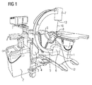
- Fig. 1 shows a Lithotripsiestrom, as for users with less need for stone treatments is appropriate. It includes a mobile patient table 1, a mobile, too for other purposes usable X-ray C-arm device 2 and a likewise mobile lithotripter 3. The mentioned assemblies are via a common mechanical interface 4 fixed together.
- the X-ray C-arm device 2 comprises a C-arm 5, the lower end of an X-ray source. 6 and the upper end of which carries an image intensifier 7.
- the focal point 8 of the Adjust the therapy head 9 of the lithotripter 3 Before the Performing a stone treatment is the focal point 8 of the Adjust the therapy head 9 of the lithotripter 3 so that he struck by a central beam 10 of the X-ray source 6 in addition to being in the isocenter of the x-ray C-arm device 2 or at least arranged in the vicinity is.
- the therapy head 9 To represent the focus point is the therapy head 9 arranged a folding bracket 12, the one in X-ray wearing visible metal ball.
- a crosshair disc 14 (not shown in FIG. 1) required at the entrance surface 13 of the image intensifier 7 is to install.
- a crosshair disc 14 (not shown in FIG. 1) required at the entrance surface 13 of the image intensifier 7 is to install.
- a crosshair disc 14 (not shown in FIG. 1) required at the entrance surface 13 of the image intensifier 7 is to install.
- lithotripsy The system is already equipped with the image intensifier factory with a removable crosshair disc equipped. If, however
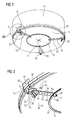
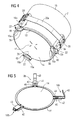
- Figs. 2 to 4 show two embodiments of a first Device variant, which one on the outer peripheral surface 15 of the image intensifier 7 fixable holding device 16 includes.
- the crosshair disc 14 In the assembled state - on the following always reference is taken - is the crosshair disc 14 on the entrance surface 13 in the adjusted state so that on her existing crosshair 17 the entry point of the central beam 10 or the X-ray optical center of the entrance surface 13 marked.
- the crosshair disk 14 is over total 3 evenly distributed over the circumference of the image intensifier 7 Connecting elements 18 with the holding device 16th connected.
- the holding device 16 comprises three with a Clamp 20 on the outer peripheral surface 15 clamped holding elements 19, with which the radially outer ends 22 the connecting elements 18 are mechanically coupled.
- the Connecting elements 18 are strip-shaped and are made of a solid material, such as aluminum sheet. Except for the outer ends 22 are the connecting elements 18 in several formed by transverse notches Predetermined breaking points 23 separate longitudinal sections 24 divided. By canceling one or more longitudinal sections 24 can be an adaptation to the respective diameter of the image intensifier 7. Each longitudinal section 24 is penetrated by a bore 25, for fixing the connecting element 18 at the crosshair disc is used. These has a stiffened edge 27, for example, also from a Aluminum material in which a bore 26 is present. The attachment of the connecting element 18 takes place for example by a both holes 22, 26 by cross Screw, (not shown). In the area of a connecting element 18, the edge 27 has a radially inwardly directed, penetrated by a bore 31 and for fixing the crosshair disk 14 serving projection 28.
- the outer end 22 of a connecting element 18 is hook-shaped bent over, wherein the angle ⁇ between the bent Section 29 and the remaining connection element smaller 90 ° is.
- On the radially outward-facing side of the section 29 is a central, in the longitudinal direction of the connecting element 18 extending groove 30 available. In this groove engages a pressure element fixed to the respective holding element 19 32 with a spring-loaded in the direction of engagement locking element (not shown).
- the point of intervention at the section 29 is positioned so that the end 22 of the connecting element 18 with a directed to the entrance surface 13, resulting from the inclination of section 29 Force is applied.
- a set screw 33 can be the engaging in the groove 30 spring-loaded Locking piece in the radial direction around an area Adjust, about the length 34 of a longitudinal section 24th equivalent.
- the holding elements are designed in the manner of an angle profile Sheet metal parts, one of whose legs 35 on the outer peripheral surface 15 and the other leg 36 at the entrance surface 13 of the image intensifier 7 is applied. From the thigh 35 is a this extending beyond the entrance surface 13 addition Tab 37, which carries the pressure piece 33.
- the Legs 35 lie with curved side edges 41 linear on the outer peripheral surface 15 at.
- Figure 4 shows an embodiment in which the connecting elements 18a made of elastic material in the form of a band are made.
- the fixation on a crosshair disc 14 can take place, for example, that this a slot 38th through which the radially inner end of the connecting element 18a passed through to form a loop is.
- the outer end 22 is on the holding elements 19 a releasably clamped.
- the clamping is done by a extending transversely across the connector 18a Bridge 39, the protruding ends screwed to the support member 19a are.
- Alone through the elasticity of the fasteners 18a is a certain amount of room for adaptation to differently sized image intensifier 7 available.
- the extent of the radial adaptability can still thereby be increased, that the connecting elements 18 a at different Longitudinal positions are clamped.
- the holding elements 19 a are by a elastic tension band 20a on the outer peripheral surface 15 of Image intensifier 7 clamped.
- the strap is with his two ends on the outside of a holding element 19'a with Help two webs 39 'clamped.
- the remaining holding elements 19a are in the same way, namely also with one Stem 39 'fixed to the strap 20a.
- Around a defined axial position to create for the holding elements 19a they have on its side facing the entrance surface 13 a radially inwardly extending, plate-shaped stop 40th on, which bears against the entrance surface 13 of the image intensifier 7.
- FIGS. 5 to 7 show a device variant, in which the fixation to an image intensifier 7 using the Connecting elements 18b itself takes place.
- the connecting elements 18b are composed of a first section 42 and a second section Section 43 formed.
- the first section 42 is an im essential plate-shaped part with rectangular outline. On its in the assembled state of the entrance surface 13 facing Side is one over its entire length extending recess 44 introduced.
- the width of the recess 44 is less than the width of the first section 42, so that the recess 44 of two lateral edge strips 45 flanked.
- the first section 42 is still from a centrally located, parallel to the longitudinal extent the recess 44 extending slot 46 passes.
- the edge strips 45 each have a bore 51, with which the section 42 can be fixed on the edge 27, can be screwed on.
- the second section 43 is formed of two flat legs Elbow, wherein the first leg 48 at the side Guide through the edge strips 45 longitudinally displaceable in the recess 44 rests and the second leg 49 with the first leg 48 forms an angle ⁇ , which is smaller than 90 ° is.
- the second leg 49 is in the assembled state at the Outside peripheral surface 15 of an image intensifier 7 on. Thereby that included by the two legs angle ⁇ is smaller than 90 °, the second leg 49 is only with his free at the image intensifier.
- In the area of the two Leg 48, 49 connecting groove 50 of the second section In this way, a space is created, 43 For example, a beading the entrance surface can accommodate widened edge of the image intensifier.
- the first leg 48 has a centrally arranged row of Threaded holes 52, wherein at least in one of the threaded holes 52 a the slot 46 sweeping screw (not shown) is screwed with its threaded end.
- the second section 43 in different Longitudinal positions on the first portion 42 can be fixed and thereby the device to differently sized image intensifier customizable.
- One of the three connecting elements 19b namely That provided in Fig. 8 by the reference numeral 18'b, is so designed that it is on the outer peripheral surface 15 of a Image intensifier 7 exerts a force while the remaining two connecting elements 18b with their two legs 49th presses on the peripheral surface 15 of the image intensifier 7.
- the two legs 48 'and 49' of the connecting element 18'b are designed substantially similar to the corresponding ones Legs of the connecting elements 19b.
- the second leg 49 ' is, however, on the first leg 48' by a parallel to the Plinkenen the legs 48 ', 49' extending axis pivotable.
- the two legs 48 ', 49' are coaxial over two connected side by side coil springs 53.
- the respective outer spring ends 54 are connected to the leg 48 'and the respective inner spring ends 55 are with the second leg 49 'connected.
- Between the two Leg springs 53 is an axial distance, in the one frontally on the leg 49 'integrally formed extension 56 protrudes.
- the extension 56 is within the leg springs 53 to one extending into the coil springs 53 on both sides Web 57 formed.
- the web 57 serves to fix the position or as a pivot axis at a pivoting of the leg 49 '.
- a device or a retrofit kit of the type described can have several crosshairs 14 with different Diameters include, which in addition to the length variability the connecting elements 18 a further adaptation at image intensifier 7 different sizes.
Landscapes
- Health & Medical Sciences (AREA)
- Life Sciences & Earth Sciences (AREA)
- Medical Informatics (AREA)
- Engineering & Computer Science (AREA)
- Nuclear Medicine, Radiotherapy & Molecular Imaging (AREA)
- Surgery (AREA)
- Molecular Biology (AREA)
- Public Health (AREA)
- Biomedical Technology (AREA)
- Heart & Thoracic Surgery (AREA)
- Radiology & Medical Imaging (AREA)
- Veterinary Medicine (AREA)
- Animal Behavior & Ethology (AREA)
- General Health & Medical Sciences (AREA)
- Vascular Medicine (AREA)
- Orthopedic Medicine & Surgery (AREA)
- Physics & Mathematics (AREA)
- Biophysics (AREA)
- High Energy & Nuclear Physics (AREA)
- Optics & Photonics (AREA)
- Pathology (AREA)
- Apparatus For Radiation Diagnosis (AREA)
Abstract
Description
Claims (17)
- Vorrichtung zum Einstellen der Fokuslage des Therapiekopfes (9) einer ein Röntgensystem umfassenden Lithotripsieanlage, mit einer an einem Bildverstärker (7) des Röntgensystems anbringbaren Fadenkreuzscheibe (14), dadurch gekennzeichnet, dass sich vom Rand der Fadenkreuzscheibe (14) längenvariable Verbindungselemente (18) wegerstrecken, deren von der Fadenkreuzscheibe (14) wegeweisendes äußeres Ende (22) mittel- oder unmittelbar am Bildverstärker (7) fixierbar ist.
- Fadenkreuzvorrichtung nach Anspruch 1, dadurch gekennzeichnet, dass drei über den Umfang der Fadenkreuzscheibe (14) verteilte Verbindungselemente (18) vorhanden sind.
- Vorrichtung nach Anspruch 1 oder 2, dadurch gekennzeichnet, dass das äußere Ende (22) eines Verbindungselements (18) an einer an der Außenumfangsfläche (15) des Bildverstärkers (7) angebrachten Halteeinrichtung (16) fixiert ist.
- Vorrichtung nach Anspruch 3, dadurch gekennzeichnet, dass jedem Verbindungselement (18) ein an der Außenumfangsfläche (15) des Bildverstärkers (7) fixierbares Halteelement (19) zugeordnet ist.
- Vorrichtung nach Anspruch 4, gekennzeichnet durch ein um die Außenumfangsfläche (15) des Bildverstärkers (7) legbare, die Halteelemente (19) am Bildverstärker (7) festklemmendes Spannband (20).
- Vorrichtung nach Anspruch 4 oder 5, dadurch gekennzeichnet, dass die Halteelemente (19) lösbar am Bildverstärker (7) fixierbar sind.
- Vorrichtung nach Anspruch 6, gekennzeichnet durch ein Spannband (20a) aus elastischem Material.
- Vorrichtung nach einem der Ansprüche 1 bis 7, dadurch gekennzeichnet, dass die Fadenkreuzscheibe (14) lösbar an den Verbindungselementen (18) fixiert ist.
- Vorrichtung nach einem der vorhergehenden Ansprüche, dadurch gekennzeichnet, dass ein Verbindungselement in mehrere von Sollbruchstellen voneinander abgegrenzte Längsabschnitte (24) unterteilt ist, wobei jeder Längsabschnitt (24) ein Fixierelement aufweist, mit dem das Verbindungselement (18) am Rand (27) der Fadenkreuzscheibe (14) fixiert ist.
- Vorrichtung nach Anspruch 9, dadurch gekennzeichnet, dass das Fixierelement eine einen Längsabschnitt (24) durchsetzende Bohrung (25) ist.
- Vorrichtung nach einem der Ansprüche 3 bis 10, gekennzeichnet durch eine Schnappverbindung zwischen dem äußeren Ende (22) eines Verbindungselements (18) und einem Halteelement (19).
- Vorrichtung nach einem der Ansprüche 3 bis 11, dadurch gekennzeichnet, dass zwischen dem äußeren Ende (22) eines Verbindungselementes (18) und einem Halteelement ein Justierteil angeordnet ist, mit dem der Abstand zwischen Verbindungs- und Halteelement in einem der Länge eines Längsabschnitts (24) entsprechenden Ausmaß veränderbar ist.
- Vorrichtung nach einem der Ansprüche 1 bis 8, dadurch gekennzeichnet, dass ein Verbindungselement (18a) aus einem elastischen Material besteht.
- Vorrichtung nach Anspruch 13, dadurch gekennzeichnet, dass das äußere Ende (22) des Verbindungselements (18) lösbar am Halteelement (19) fixiert ist.
- Vorrichtung nach Anspruch 1 oder 2, dadurch gekennzeichnet, dass das äußere Ende (22) der Verbindungselemente (18b) hakenförmig ausgebildet ist, wobei die hakenförmigen Enden an der Außenumfangsfläche (15) des Bildverstärkers (7) ansetzbar sind und dabei wenigstens ein hakenförmiges Ende in Richtung auf die Außenumfangsfläche (15) des Bildverstärkers (7) vorspannbar ist.
- Vorrichtung nach Anspruch 15, dadurch gekennzeichnet, dass an einem vorspannbaren Ende ein mit der Außenumfangsfläche (15) zusammenwirkender federbeaufschlagter Schenkel (49') angelenkt ist.
- Vorrichtung nach Anspruch 15 oder 16, dadurch gekennzeichnet, dass ein Verbindungselement (18b) einen an der Fadenkreuzscheibe (14) fixierten ersten Abschnitt (42) und einen, vom hakenförmigen Ende gebildeten zweiten Abschnitt (43) aufweist, wobei die beiden Abschnitte in unterschiedlichen Längspositionen aneinander fixierbar sind.
Applications Claiming Priority (2)
| Application Number | Priority Date | Filing Date | Title |
|---|---|---|---|
| DE102004010466A DE102004010466B4 (de) | 2004-03-01 | 2004-03-01 | Vorrichtung zum Einstellen der Fokuslage des Therapiekopfes einer Lithotripsieanlage |
| DE102004010466 | 2004-03-01 |
Publications (2)
| Publication Number | Publication Date |
|---|---|
| EP1570786A1 true EP1570786A1 (de) | 2005-09-07 |
| EP1570786B1 EP1570786B1 (de) | 2006-09-20 |
Family
ID=34745374
Family Applications (1)
| Application Number | Title | Priority Date | Filing Date |
|---|---|---|---|
| EP05101052A Expired - Lifetime EP1570786B1 (de) | 2004-03-01 | 2005-02-14 | Vorrichtung zum Einstellen der Fokuslage des Therapiekopfes einer Lithotripsieanlage |
Country Status (3)
| Country | Link |
|---|---|
| US (1) | US7104688B2 (de) |
| EP (1) | EP1570786B1 (de) |
| DE (2) | DE102004010466B4 (de) |
Families Citing this family (5)
| Publication number | Priority date | Publication date | Assignee | Title |
|---|---|---|---|---|
| DE102006019418A1 (de) * | 2006-04-26 | 2007-10-31 | Siemens Ag | Bildmarkiervorrichtung zum Markieren eines Justierbilds eines Bildverstärkers |
| DE102008019635A1 (de) | 2008-04-18 | 2009-10-22 | Siemens Aktiengesellschaft | Medizinischer Arbeitsplatz |
| DE102011082680B4 (de) * | 2011-09-14 | 2019-12-24 | Siemens Healthcare Gmbh | Anlage |
| US9360124B2 (en) | 2013-03-15 | 2016-06-07 | Cook Medical Technologies Llc | Bi-directional valve device for selective control of fluid flow through multiple converging paths |
| JP2022519576A (ja) | 2019-02-04 | 2022-03-24 | マークスマン ターゲティング,インコーポレイテッド | 医療用撮像システムの受像器に装着されるカラー装置 |
Citations (3)
| Publication number | Priority date | Publication date | Assignee | Title |
|---|---|---|---|---|
| DE4003350C1 (en) * | 1990-02-05 | 1991-04-25 | Dornier Medizintechnik Gmbh, 8000 Muenchen, De | C-bow X=ray appts. setter for lithotriptor - uses metal sphere on support as reference element for position of therapy focus |
| DE4400997A1 (de) * | 1994-01-14 | 1995-07-27 | Siemens Ag | Medizinisches Gerät mit einer Röntgendiagnostikeinrichtung |
| DE10231071A1 (de) * | 2002-07-10 | 2004-01-22 | Philips Intellectual Property & Standards Gmbh | Therapiekombination |
Family Cites Families (4)
| Publication number | Priority date | Publication date | Assignee | Title |
|---|---|---|---|---|
| US5142559A (en) * | 1990-05-11 | 1992-08-25 | The Research Foundation Of State University Of New York | Radiation detection system including radiation alignment means and isocentrically rotatable detectors |
| DE4112148A1 (de) * | 1991-04-13 | 1992-10-15 | Philips Patentverwaltung | Lithotripsie-arbeitsplatz |
| US5283808A (en) * | 1992-07-01 | 1994-02-01 | Diasonics, Inc. | X-ray device having a co-axial laser aiming system in an opposed configuration |
| US6267502B1 (en) * | 1998-04-10 | 2001-07-31 | Minrad Inc. | Alignment verification device and method of using the same with a visual light beam and an x-ray |
-
2004
- 2004-03-01 DE DE102004010466A patent/DE102004010466B4/de not_active Expired - Fee Related
-
2005
- 2005-02-14 DE DE502005000104T patent/DE502005000104D1/de not_active Expired - Lifetime
- 2005-02-14 EP EP05101052A patent/EP1570786B1/de not_active Expired - Lifetime
- 2005-03-01 US US11/070,112 patent/US7104688B2/en not_active Expired - Lifetime
Patent Citations (3)
| Publication number | Priority date | Publication date | Assignee | Title |
|---|---|---|---|---|
| DE4003350C1 (en) * | 1990-02-05 | 1991-04-25 | Dornier Medizintechnik Gmbh, 8000 Muenchen, De | C-bow X=ray appts. setter for lithotriptor - uses metal sphere on support as reference element for position of therapy focus |
| DE4400997A1 (de) * | 1994-01-14 | 1995-07-27 | Siemens Ag | Medizinisches Gerät mit einer Röntgendiagnostikeinrichtung |
| DE10231071A1 (de) * | 2002-07-10 | 2004-01-22 | Philips Intellectual Property & Standards Gmbh | Therapiekombination |
Also Published As
| Publication number | Publication date |
|---|---|
| EP1570786B1 (de) | 2006-09-20 |
| DE502005000104D1 (de) | 2006-11-02 |
| DE102004010466A1 (de) | 2005-10-06 |
| US20050232398A1 (en) | 2005-10-20 |
| DE102004010466B4 (de) | 2006-05-04 |
| US7104688B2 (en) | 2006-09-12 |
Similar Documents
| Publication | Publication Date | Title |
|---|---|---|
| DE69905707T2 (de) | Wirbelsäulen-osteosynthesesystem mit spannvorrichtung, insbesondere zur vorderen fixierung | |
| DE69925374T2 (de) | Spinales osteosynthesesystem mit verbesserter stabilität | |
| DE69206318T2 (de) | Verriegelbares Verbindungsstück für Verankerungselemente für die Wirbelsäulenosteosynthese. | |
| DE3000432C2 (de) | ||
| DE69021428T2 (de) | Wirbelsäulenimplantat für Osteosesyntheseeinrichtung. | |
| DE60201120T2 (de) | Vorrichtung zur Auffindung der Position von Schraubenlöchern zur Fixierung eines Markraumnagels | |
| DE2929455C2 (de) | ||
| EP0509322B1 (de) | Verbindungseinrichtung zum verstellbaren Verbinden eines ersten mit einem zweiten Konstruktionselement, insbesondere von Rohren oder Stäben für eine Fixationsvorrichtung | |
| DE60320544T2 (de) | Wirbelsäulen-osteosynthesesystem | |
| EP1386588B1 (de) | Zielgerät für einen Verriegelungsnagel | |
| DE69403653T2 (de) | Aufbauteil für eine osteosynthetische vorrichtung | |
| DE3119680C2 (de) | Handoperationstisch | |
| DE202005019277U1 (de) | Knochenplatte mit wenigstens zwei Langlöchern und Knochenplattensystem | |
| EP2934359B1 (de) | Instrumentenhalter | |
| CH661860A5 (de) | Vorrichtung zur externen fixierung von knochenfragmenten. | |
| DE9115231U1 (de) | Äußerer Spanner | |
| DE29922734U1 (de) | Vorrichtung für die Positionierung und Befestigung | |
| DE4110123A1 (de) | Elastische klammer | |
| DE3614305A1 (de) | Aeusserlich anwendbarer fixateur | |
| EP2160986B1 (de) | Vorrichtung zur Befestigung einer Markervorrichtung an einem Knochen | |
| DE60301908T2 (de) | Externes Fixationssystem zur Versorgung von Knochenbrüchen | |
| EP1188416B1 (de) | Pedikelschraube für intervertebrale Stützelemente | |
| EP1570786B1 (de) | Vorrichtung zum Einstellen der Fokuslage des Therapiekopfes einer Lithotripsieanlage | |
| EP0146872A2 (de) | Vorrichtung zum Einrichten von Knochenabschnitten und/oder Knochenfragmenten | |
| DE102006034903A1 (de) | Orthopädische Hilfsmittel |
Legal Events
| Date | Code | Title | Description |
|---|---|---|---|
| PUAI | Public reference made under article 153(3) epc to a published international application that has entered the european phase |
Free format text: ORIGINAL CODE: 0009012 |
|
| AK | Designated contracting states |
Kind code of ref document: A1 Designated state(s): AT BE BG CH CY CZ DE DK EE ES FI FR GB GR HU IE IS IT LI LT LU MC NL PL PT RO SE SI SK TR |
|
| AX | Request for extension of the european patent |
Extension state: AL BA HR LV MK YU |
|
| 17P | Request for examination filed |
Effective date: 20051010 |
|
| GRAP | Despatch of communication of intention to grant a patent |
Free format text: ORIGINAL CODE: EPIDOSNIGR1 |
|
| AKX | Designation fees paid |
Designated state(s): CH DE FR LI |
|
| GRAS | Grant fee paid |
Free format text: ORIGINAL CODE: EPIDOSNIGR3 |
|
| GRAA | (expected) grant |
Free format text: ORIGINAL CODE: 0009210 |
|
| AK | Designated contracting states |
Kind code of ref document: B1 Designated state(s): CH DE FR LI |
|
| REG | Reference to a national code |
Ref country code: CH Ref legal event code: EP Ref country code: CH Ref legal event code: NV Representative=s name: SIEMENS SCHWEIZ AG |
|
| REF | Corresponds to: |
Ref document number: 502005000104 Country of ref document: DE Date of ref document: 20061102 Kind code of ref document: P |
|
| ET | Fr: translation filed | ||
| PLBE | No opposition filed within time limit |
Free format text: ORIGINAL CODE: 0009261 |
|
| STAA | Information on the status of an ep patent application or granted ep patent |
Free format text: STATUS: NO OPPOSITION FILED WITHIN TIME LIMIT |
|
| 26N | No opposition filed |
Effective date: 20070621 |
|
| REG | Reference to a national code |
Ref country code: CH Ref legal event code: PCAR Free format text: SIEMENS SCHWEIZ AG;INTELLECTUAL PROPERTY FREILAGERSTRASSE 40;8047 ZUERICH (CH) |
|
| REG | Reference to a national code |
Ref country code: FR Ref legal event code: PLFP Year of fee payment: 12 |
|
| REG | Reference to a national code |
Ref country code: DE Ref legal event code: R081 Ref document number: 502005000104 Country of ref document: DE Owner name: SIEMENS HEALTHCARE GMBH, DE Free format text: FORMER OWNER: SIEMENS AKTIENGESELLSCHAFT, 80333 MUENCHEN, DE |
|
| REG | Reference to a national code |
Ref country code: FR Ref legal event code: PLFP Year of fee payment: 13 |
|
| REG | Reference to a national code |
Ref country code: CH Ref legal event code: PCOW Free format text: NEW ADDRESS: WERNER-VON-SIEMENS-STRASSE 1, 80333 MUENCHEN (DE) |
|
| REG | Reference to a national code |
Ref country code: FR Ref legal event code: PLFP Year of fee payment: 14 |
|
| PGFP | Annual fee paid to national office [announced via postgrant information from national office to epo] |
Ref country code: CH Payment date: 20200504 Year of fee payment: 16 |
|
| PGFP | Annual fee paid to national office [announced via postgrant information from national office to epo] |
Ref country code: DE Payment date: 20210419 Year of fee payment: 17 |
|
| PG25 | Lapsed in a contracting state [announced via postgrant information from national office to epo] |
Ref country code: LI Free format text: LAPSE BECAUSE OF NON-PAYMENT OF DUE FEES Effective date: 20210228 Ref country code: CH Free format text: LAPSE BECAUSE OF NON-PAYMENT OF DUE FEES Effective date: 20210228 |
|
| REG | Reference to a national code |
Ref country code: DE Ref legal event code: R119 Ref document number: 502005000104 Country of ref document: DE |
|
| PG25 | Lapsed in a contracting state [announced via postgrant information from national office to epo] |
Ref country code: DE Free format text: LAPSE BECAUSE OF NON-PAYMENT OF DUE FEES Effective date: 20220901 |
|
| PGFP | Annual fee paid to national office [announced via postgrant information from national office to epo] |
Ref country code: FR Payment date: 20240226 Year of fee payment: 20 |