EP1570196B1 - Bürstendichtung zum dichten eines spaltes zwischen einem rotor und einem stator - Google Patents
Bürstendichtung zum dichten eines spaltes zwischen einem rotor und einem stator Download PDFInfo
- Publication number
- EP1570196B1 EP1570196B1 EP03775400A EP03775400A EP1570196B1 EP 1570196 B1 EP1570196 B1 EP 1570196B1 EP 03775400 A EP03775400 A EP 03775400A EP 03775400 A EP03775400 A EP 03775400A EP 1570196 B1 EP1570196 B1 EP 1570196B1
- Authority
- EP
- European Patent Office
- Prior art keywords
- brush
- brush ring
- ring carrier
- face
- carrier
- Prior art date
- Legal status (The legal status is an assumption and is not a legal conclusion. Google has not performed a legal analysis and makes no representation as to the accuracy of the status listed.)
- Expired - Lifetime
Links
- 238000007789 sealing Methods 0.000 title claims description 22
- 239000000969 carrier Substances 0.000 claims abstract description 23
- 239000011324 bead Substances 0.000 claims description 12
- 230000001681 protective effect Effects 0.000 claims description 3
- 239000012530 fluid Substances 0.000 description 10
- 238000004519 manufacturing process Methods 0.000 description 8
- 230000000694 effects Effects 0.000 description 7
- 238000006073 displacement reaction Methods 0.000 description 2
- 230000002427 irreversible effect Effects 0.000 description 2
- 230000002411 adverse Effects 0.000 description 1
- 150000001875 compounds Chemical class 0.000 description 1
- 238000010276 construction Methods 0.000 description 1
- 238000002788 crimping Methods 0.000 description 1
- 230000001066 destructive effect Effects 0.000 description 1
- 238000009434 installation Methods 0.000 description 1
- 230000002093 peripheral effect Effects 0.000 description 1
- 238000011144 upstream manufacturing Methods 0.000 description 1
Images

Classifications
-
- F—MECHANICAL ENGINEERING; LIGHTING; HEATING; WEAPONS; BLASTING
- F16—ENGINEERING ELEMENTS AND UNITS; GENERAL MEASURES FOR PRODUCING AND MAINTAINING EFFECTIVE FUNCTIONING OF MACHINES OR INSTALLATIONS; THERMAL INSULATION IN GENERAL
- F16J—PISTONS; CYLINDERS; SEALINGS
- F16J15/00—Sealings
- F16J15/16—Sealings between relatively-moving surfaces
- F16J15/32—Sealings between relatively-moving surfaces with elastic sealings, e.g. O-rings
- F16J15/3284—Sealings between relatively-moving surfaces with elastic sealings, e.g. O-rings characterised by their structure; Selection of materials
- F16J15/3288—Filamentary structures, e.g. brush seals
Definitions
- Brush seals are used successfully in fluid flow machines, for example, to reduce the leakage current between a rotor and a stator.
- a disadvantage of many brush seals is that the brush ring carriers are often not manufactured in one piece. This results in operation out of roundness of the brush seals and the secondary seal to the housing, which adversely affect the sealing effect of the overall arrangement and thus the efficiency of the turbomachine.
- a brush seal is known in which the brush ring is welded between two annular one-piece brush ring carriers. This entire unit, consisting of two brush ring carriers and a brush ring located therebetween, is inserted into a corresponding groove of the stator. Ie. Each brush ring requires two brush ring carriers and one groove in the stator to accommodate the brush holder.
- From DE 197 C2 is a brush seal in which a brush ring between two brush ring carriers is held and the brush ring carriers are connected by crimping. Also in this brush seal per brush ring two brush ring carrier and a groove in the stator are required.
- the invention has for its object to provide a brush seal arrangement, with respect to Sealing effect and manufacturing and assembly costs is further improved.
- a brush seal according to the invention for sealing a gap between a rotor and a stator, in particular a turbomachine, with at least one brush ring having a plurality of sealing bristles, with which two extending in the circumferential direction of the rotor annular brush holders, each brush ring between a first.
- the manufacturing and assembly costs can be significantly reduced, since by merely nesting of the second brush ring carrier and the first brush ring carrier axial and radial fixation of the second brush ring carrier takes place, which complicated and costly adjustments and fixations prevented.
- the brush ring carrier is rotationally symmetrical, so that the roundness is maintained even under changing operating conditions.
- first brush ring carrier and a second brush ring carrier. This should be a distinction between two identical components.
- the first Bürsteinringica is arranged in the flow direction of the fluid flowing through the sealing gap downstream of the second brush ring carrier.
- a groove is formed between a first brush ring carrier in the flow direction of the fluid to be sealed and a second brush ring carrier in the flow direction of the fluid to be sealed, and that the groove serves to receive the brush ring.
- the brush ring is also axially and radially fixed without additional effort for the centering and fixing in the brush ring carriers when the second brush ring carrier is pushed onto the first brush ring carrier.
- the groove for receiving the brush ring can be present either completely in the first brush ring carrier or in the second brush ring carrier or partially in both.
- the brush ring is the actual sealing element, which consists of a variety of sealing bristles.
- the sealing bristles are arranged in the case of a radial seal so that the sealing bristles when installed touch the rotor straight.
- At least one first brush ring carrier has on its first end face a shoulder with a circumferential groove, that at least a second brush ring carrier has a circumferential projection on its second end face, and that the projection of the second brush ring carrier with the paragraph and the circumferential groove of an adjacently arranged first brush ring carrier cooperates such that an axial and radial fixation of the second brush ring carrier takes place relative to the first brush ring carrier.
- This connection between the first brush ring carrier and the second brush ring carrier is also designed as a snap connection, in particular as a permanent snap connection.
- this compound provides a good axial and radial fixation of the second brush ring carrier at the same time low production costs, since both the paragraph and the circumferential groove and the projection in a single clamping can be easily produced on a lathe.
- At least one brush ring carrier has a shoulder with a circumferential groove on its first end face, that at least one brush ring carrier has a circumferential projection on its second end face, and that the projection of the first end side of the at least one brush ring carrier with the paragraph and the circumferential groove of an adjacently arranged further brush ring carrier cooperates.
- a brush ring carrier has a thickness of about 12 mm, so that a brush ring can be arranged every 12 mm. It also follows that the brush seal according to the invention is very compact and thus more brush rings can be provided with the same space than hitherto usual.
- a brush ring carrier is held at least indirectly on the stator. This can be done by a groove in the stator, screws or other means known in the art.
- the circumferential groove is arranged in the first mounted part and the locking lug is in the newly deferred part.
- the locking connection is insoluble (irreversible), as may be provided according to the invention, this has the advantage that in the case of a manufacturing error only the last mounted brush ring carrier must be dismantled by twisting the projection destructive.
- the brush ring carrier or carriers have a support plate and / or a guard ring which extend from the brush ring carrier in the direction of the rotor and against which the brush seal rests axially supported on at least one axial side.
- Such support plates and protective rings are known per se from the prior art;
- a support plate and a guard ring can be unscrewed directly from the brush ring carrier, so that as well remains integral by the use of the support means of the brush ring carrier and the number of required components and thus the production cost remains minimal.
- the support plate and the guard ring are radially elastic, so that in the case of a start-up of the rotor on the support means they can avoid in the radial direction without causing damage or to be damaged itself.
- the axial support means return to their original shape and position.
- the effect of the brush seal according to the invention can be further improved if the rotor to be sealed has at least one peripheral bead, and the at least one bead is arranged offset relative to the brush ring (s).
- This bead which may for example have a height of 0.7 mm, deflects the fluid flow exiting through the sealing gap so that the brush rings located downstream of the bead can not be damaged by the fluid jet coming from the upstream.
- the brush seal and the axial support means can be slipped over the bead, and that they are not damaged during the assembly of the brush seal according to the invention.
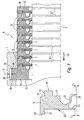
- Figure 1 shows a first embodiment of a seal according to the invention, which is arranged between a stator 1 and a rotor 3 of a turbomachine.
- the multi-stage brush seal in the first exemplary embodiment is denoted by 5 in its entirety in FIG.
- the brush seal 5 consists essentially of brush rings 7, which are fixed axially and radially in brush ring carriers 9, 11 and 13.
- Brush seals according to the invention can also be single-stage, d. H. be carried out with only one brush ring.
- FIG 1 a single brush ring carrier 9 has been shown enlarged. Based on this single brush ring carrier 9 whose form and function are explained below.
- the other brush ring carrier 9 are constructed identically.
- the other brush ring carrier 11 and 13 are partially identical.
- the brush ring carrier 9 has a first end face 15. At this first end face 15, a groove 17 is recessed in the a brush ring 7 can be inserted. On the outer diameter of the brush ring carrier 9, a shoulder 19 is formed with a circumferential groove 21 in the first end face 15.
- a circumferential projection 25 is present, which is dimensioned so that it can be pushed onto a shoulder 19 of a brush ring carrier 9 arranged adjacently. This results in an axial and radial fixation of two adjacently arranged brush ring carriers 9 to each other.
- a latching nose 27 is provided, which can engage in the circumferential groove 21 on a first end face 17 of an adjacently arranged brush ring carrier 9.
- the Umfansgnut 21 and the locking lug 27 form a snap connection in the embodiment shown in Fig. 1.
- a plurality of brush ring carriers 9 are interconnected, in which the projection 25 on the second end face 23 of a brush ring carrier 9 is pushed onto a shoulder 19 of a first of the first face 15 of a brush ring carrier 9 arranged adjacently ,
- the groove 17 on the first end face 15 is formed with respect to diameter and depth so that a brush ring 7 is clamped between two brush ring carrier 9 and fixed axially and radially, when these brush ring carrier 9 are locked together.
- this latching is advantageously carried out in the way that, as shown, the circumferential groove 21 is located in the first assembled part and the locking lug 27 is in the newly deferred part. If, like this may be provided according to the invention, the latching connection is insoluble (irreversible), this has the advantage that in the case of a manufacturing error, only the last mounted ring 9 by twisting the projection 25 must be destructively dismantled.
- a support plate 29 is provided on the first end face 15 of the brush ring carrier 9.
- the first end face 15 is arranged in front of the brush holder 9 in the direction of flow of the fluid flowing through the sealing gap.
- the flow direction is shown by an arrow 30.
- the support plates 29 are arranged after a brush ring 7 and are radially elastic, since in the Bürstringani 9 a groove 31 is recessed. If the rotor 3 strikes, the gap C 2 between the rotor 3 and the support plate 29 would disappear and the support plate 29 would spring back radially.
- a guard ring 33 is provided, which is less elastic in the axial direction than the support plate 29, since they are usually provided with a larger gap C 1 to the rotor 3.
- the second end face 23 is arranged in the flow direction 30 of the fluid flowing through the sealing gap in front of a brush ring 7.
- the radial elasticity of the support plate 29 or of the guard ring 33 between the two embodiments shown in the enlargement in Figure 1 on the first end face 15 and on the second end face 23 can be varied.
- the gap c 1 between guard ring 33 and rotor 3 is usually slightly larger than a gap c 2 between the support plate 29 and the rotor 3, whereby a rubbing of the guard ring 33 is prevented. Namely, before it comes to the rubbing of the guard ring 33, the brush seal 5 deviates from the rotor 3 in the axial direction (see double arrow S).
- the brush ring carrier 13 which is arranged on the right in FIG. 1 as the end piece, differs from the brush ring carriers 9 in that only a second end face 23 is formed according to the invention with a projection 25 and a latching nose 27.
- the first end face 15 is formed in this brush ring carrier 13 as a flat surface.
- the brush ring carrier 11 differs from the brush ring carriers 9 described in detail in that only a first end face 15 with groove 17, shoulder 19 and circumferential groove 21 and support plate 29 is formed.
- the second end face 23 is formed as a plane surface.
- a brush ring carrier 9 can be fastened in the manner described above.
- a further plane surface 38 is formed on the brush ring carrier 11, which runs parallel to the second end face 23.
- a second groove 36 is pierced, in which the brush ring carrier 11 is introduced.
- the brush seal 5 according to the invention is connected to the stator 1 in such a way that a certain radial displacement and adjustment, which is indicated in Figure 1 by the double arrow S, is possible. This radial displacement can be used during assembly to align the brush seal 5 relative to the rotor 3.
- the brush ring carrier 11, 9 and 13 can be additionally connected and secured by screws (not shown).
- circumferential beads 37 are provided between the brush rings 7, which divert the fluid escaping through the sealing gap such that the brush ring 7 located downstream of a bead 37 is not damaged by the outflowing fluid and the sealing effect of the brush seal 5 according to the invention is improved.
- FIG. 2 shows a second embodiment of a brush seal 5 according to the invention.
- the brush seal 5 according to the invention seals a rotor 3, in particular a turbine rotor.
- the basic structure is the same in this embodiment as in the embodiment of Figure 1. Therefore, a detailed description is omitted. Also, not all reference numerals are entered for reasons of clarity.
- brush rings 7 are fastened in the brush ring carrier 11 by means of brush ring carriers 43.
- the brush ring carriers 43 are constructed similarly to the brush ring carriers 9 described above.
- the invention is not limited to two brush ring carrier 43. Rather, the number of brush rings 7 depends on the desired use of the brush seal arrangement according to the invention. By this construction, the space required for the brush seal 5 according to the invention can be reduced and the production cost can be reduced.
- the brush ring carrier 11 and / or the brush rings 9 and 13 may be additionally connected to each other by screws, not shown.
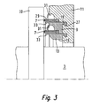
- FIG. 3 shows a third exemplary embodiment of a brush seal 5 according to the invention using the example of a compensating piston 39 of a rotor 3.
- the brush seal 5 is formed as an axial seal.
- the sealing bristles of the brush rings 7 are arranged cylindrically in this embodiment.
- the diameters of the brush ring carriers 11, 9 and 13 are coordinated with one another in such a way that they can be connected to each other in the axial direction by the snap connection described above.
Landscapes
- Engineering & Computer Science (AREA)
- General Engineering & Computer Science (AREA)
- Mechanical Engineering (AREA)
- Sealing Devices (AREA)
- Turbine Rotor Nozzle Sealing (AREA)
- Sealing Of Bearings (AREA)
Description
- Bürstendichtungen werden beispielsweise in Strömungsmaschinen mit Erfolg eingesetzt, um den Leckagestrom zwischen einem Rotor und einem Stator zu verringern. Nachteilig an vielen Bürstendichtungen ist es, dass die Bürstenringträger oft nicht einstückig hergestellt werden. Daraus ergeben sich im Betrieb Unrundheiten der Bürstendichtungen und der sekundären Dichtung zum Gehäuse, die sich nachteilig auf die Dichtwirkung der Gesamtanordnung und damit auf den Wirkungsgrad der Strömungsmaschine auswirken.
- Aus der DE 199 38 268 A1 ist eine Bürstendichtung bekannt, bei welcher der Bürstenring zwischen zwei ringförmigen einstückigen Bürstenringträgern eingeschweißt wird. Diese gesamte Einheit, bestehend aus zwei Bürstenringträgern und einem dazwischen befindlichen Bürstenring wird in eine entsprechende Nut des Stators eingefügt. D. h. je Bürstenring sind zwei Bürstenringträger und eine Nut im Stator zur Aufnahme der Bürstentringträger erforderlich.
- Aus der DE 197 C2 ist eine Bürstendichtung bei der ein Bürstenring zwischen zwei Bürstenringträgern gehalten wird und die Bürstenringträger durch Bördeln miteinander verbunden werden. Auch bei dieser Bürstendichtung sind je Bürstenring zwei Bürstenringträger und eine Nut im Stator erforderlich.
- Der Erfindung liegt die Aufgabe zugrunde, eine Bürstendichtungsanordnung bereitzustellen, die hinsichtlich Dichtwirkung sowie Herstellungs- und Montageaufwand weiter verbessert ist.
- Diese Aufgabe wird erfindungsgemäß bei einer erfindungsgemäßen Bürstendichtung zum Dichten eines Spaltes zwischen einem Rotor und einem Stator, insbesondere einer Strömungsmaschine, mit wenigstens einem eine Vielzahl von Dichtborsten aufweisenden Bürstenring, mit welchem zwei sich in Umfangsrichtung des Rotors erstreckenden ringförmigen Bürstenträgern, wobei jeder Bürstenring zwischen einer ersten. Stirnfläche eines ersten Bürstenringträgers und einer zwei Stirnfläche eines zweiten Bürstenringträgers fixiert, und wobei der zweite Bürstenringträger unmittelbar an dem ersten Bürstenringträger axial und radial fixiert ist, gemäß US-A-5 066 024 dadurch gelöst, dass der zweite Bürstenringträger an dem ersten Bürstenringträger durch eine Schnappverbindung fixiert ist.
- Durch diese Maßnahme kann der Herstellungs- und Montageaufwand deutlich verringert werden, da durch bloßes Ineinanderstecken von zweitem Bürstenringträger und erstem Bürstenringträger eine axiale und radiale Fixierung des zweiten Bürstenringträgers erfolgt, welche komplizierte und kostenintensive Einstellarbeiten und Fixierungen verhindert. Außerdem ist der Bürstenringträger rotationssymmetrisch aufgebaut, so dass die Rundheit auch bei wechselnden Betriebbedingungen erhalten bleibt.
- Selbstverständlich können auf diese Weise auch mehrere Bürstenringe hintereinander angeordnet werden, wobei pro zusätzlichem Bürstenring nur ein weiterer Bürstenringträger erforderlich ist. Auch dadurch ergibt sich eine erhebliche Kosteneinsparung ohne Nachteile hinsichtlich der Funktionalität und Dichtwirkung der erfindungsgemäßen Bürstendichtung. Schließlich ist auch der erforderliche Bauraum sehr klein.
- Im Zusammenhang mit der Erfindung wird nachfolgend von einem ersten Bürstenringträger und einem zweiten Bürstenringträger gesprochen. Damit soll eine Unterscheidung zweier an sich gleicher Bauteile erfolgen. Der erste Bürsteinringträger ist in Strömungsrichtung des durch den Dichtspalt strömenden Fluids stromabwärts des zweiten Bürstenringträgers angeordnet.
- Bei einer vorteilhaften Variante der Erfindung ist vorgesehen, dass zwischen einem in Strömungsrichtung des zu dichtenden Fluids ersten Bürstenringträger und einem in Strömungsrichtung des zu dichtenden Fluids zweiten Bürstenringträger eine Nut ausgebildet ist, und dass die Nut zur Aufnahme des Bürstenrings dient. Durch diese Nut wird der Bürstenring ebenfalls ohne zusätzlichen Aufwand für die Zentrierung und Fixierung desselben in den Bürstenringträgern axial und radial fixiert, wenn der zweite Bürstenringträger auf den ersten Bürstenringträger aufgeschoben wird. Erfindungsgemäß kann die Nut zur Aufnahme des Bürstenrings entweder vollständig im ersten Bürstenringträger oder im zweiten Bürstenringträger oder teilweise in beiden vorhanden sein kann.
- Der Bürstenring ist das eigentliche Dichtelement, welches aus einer Vielzahl von Dichtborsten besteht. Die Dichtborsten sind im Falle einer Radialdichtung so angeordnet, dass die Dichtborsten in eingebautem Zustand den Rotor gerade berühren.
- Bei einer weiteren vorteilhaften Ausgestaltung der Erfindung ist vorgesehen, dass mindestens ein erster Bürstenringträger auf seiner ersten Stirnseite einen Absatz mit einer Umfangsnut aufweist, dass mindestens ein zweiter Bürstenringträger auf seiner zweiten Stirnseite einen umlaufenden Vorsprung aufweist, und dass der Vorsprung des zweiten Bürstenringträgers mit dem Absatz und der Umfangsnut eines benachbart angeordneten ersten Bürstenringträgers so zusammenwirkt, dass eine axiale und radiale Fixierung des zweiten Bürstenringträgers relativ zum ersten Bürstenringträger erfolgt. Diese Verbindung zwischen erstem Bürstenringträger und zweitem Bürstenringträger ist auch als Schnappverbindung, insbesondere als unlösbare Schnappverbindung, ausgeführt sein. In jedem Fall bietet diese Verbindung jedoch eine gute axiale und radiale Fixierung des zweiten Bürstenringträgers bei gleichzeitig geringen Herstellungskosten, da sowohl der Absatz und die Umfangsnut als auch der Vorsprung in einer Aufspannung einfach auf einer Drehmaschine herstellbar sind.
- In einer weiteren erfindungsgemäßen Ausgestaltung ist vorgesehen, dass mindestens ein Bürstenringträger auf seiner ersten Stirnseite einen Absatz mit einer Umfangsnut aufweist, dass zumindest ein Bürstenringträger auf seiner zweiten Stirnseite einen umlaufenden Vorsprung aufweist, und dass der Vorsprung der ersten Stirnseite des mindestens einen Bürstenringträgers mit dem Absatz und der Umfangsnut eines benachbart angeordneten weiteren Bürstenringträgers zusammenwirkt. Dadurch ist es möglich, beliebig viele Bürstenringträger und Bürstenringe hintereinander anzuordnen, wobei mit Ausnahme eines Anfangs- und eines Endstücks lauter identische Bauteile zum Einsatz kommen können. Dadurch werden die Herstellkosten weiter verringert. Die Zahl der in Reihe angeordneten Bürstenringe wird in der Regel in Abhängigkeit des vorhandenen Bauraums und der gewünschten Dichtwirkung festgelegt werden. In praktisch ausgeführten Beispielen hat es sich als möglich erwiesen, dass ein Bürstenringträger eine Dicke von etwa 12 mm hat, so dass alle 12 mm ein Bürstenring angeordnet werden kann. Daraus ergibt sich auch, dass die erfindungsgemäße Bürstendichtung sehr platzsparend ist und somit bei gleichem Bauraum mehr Bürstenringe als bislang üblich vorgesehen werden können.
- Um die Bürstendichtung sicher relativ zum Stator zu fixieren, ist vorgesehen, dass ein Bürstenringträger mindestens mittelbar am Stator gehalten ist. Dies kann durch eine Nut im Stator, Schrauben oder andere aus dem Stand der Technik bekannte Mittel erfolgen.
- Es hat sich als vorteilhaft erwiesen, wenn die Umfangsnut in dem zuerst montierten Teil angeordnet wird und sich die Rastnase im neu aufgeschobenen Teil befindet. Wenn nämlich die Rastverbindung unlösbar (irreversibel) ist, wie dies erfindungsgemäß vorgesehen sein kann, hat dies den Vorteil, dass im Falle eines Fertigungsfehlers nur der zuletzt montierte Bürstenringträger durch Abdrehen des Vorsprungs zerstörend demontiert werden muß.
- Um die Dichtwirkung der erfindungsgemäßen Bürstendichtung zu verbessern, ist vorgesehen, dass der oder die Bürstenringträger eine Stützplatte und/oder einen Schutzring aufweisen, die sich vom Bürstenringträger in Richtung des Rotors erstrecken und an denen die Bürstendichtung an wenigstens einer Axialseite axial gestützt anliegt. Solche Stützplatten und Schutzringe sind an sich aus dem Stand der Technik bekannt; jedoch kann bei der erfindungsgemäßen Bürstendichtung eine Stützplatte und ein Schutzring direkt aus dem Bürstenringträger herausgedreht werden, so dass auch durch den Einsatz der Stützmittel der Bürstenringträger einstückig bleibt und die Zahl der benötigten Bauteile und damit auch der Herstellungsaufwand weiter minimal bleibt.
- In weiterer vorteilhafter Ausgestaltung der Erfindung sind die Stützplatte und der Schutzring radial elastisch ausgebildet, so dass im Falle eines Anlaufens des Rotors an den Stützmitteln diese in radialer Richtung ohne einen Schaden zu verursachen oder selbst beschädigt zu werden ausweichen können. Sobald der Rotor wieder in seine ursprüngliche zentrische Lage zurückgekehrt ist nehmen die axialen Stützmittel wieder ihre ursprüngliche Form und Lage ein.
- Die Wirkung der erfindungsgemäßen Bürstendichtung kann weiter verbessert werden, wenn der abzudichtende Rotor mindestens einen umlaufenden Wulst aufweist, und der mindestens eine Wulst versetzt zu dem oder den Bürstenringen angeordnet ist. Dieser Wulst, der beispielsweise eine Höhe von 0,7 mm haben kann, lenkt den durch den Dichtspalt austretenden Fluidstrom so ab, dass die stromab des Wulstes liegenden Bürstenringe von dem stromauf kommenden Fluidstrahl nicht beschädigt werden können. Selbstverständlich ist bei der Bemessung der Höhe des Wulstes darauf zu achten, dass die Bürstendichtung und die axialen Stützmittel über den Wulst geschoben werden können, bei der Montage der erfindungsgemäßen Bürstendichtung nicht beschädigt werden.
- Weitere Vorteile und vorteilhafte Ausgestaltungen sind der nachfolgenden Zeichnung, deren Beschreibung und den Patentansprüchen entnehmbar.
- Es zeigen:
- Figur 1
- ein erstes Ausführungsbeispiel einer erfindungsgemäßen Bürstendichtung im Schnitt
- Figur 2
- ein zweites Ausführungsbeispiel einer erfindungsgemäßen Bürstendichtungen an einem Ausgleichskolben einer Dampfturbine und
- Figur 3
- ein drittes Ausführungsbeispiel einer erfindungsgemäßen Bürstendichtungen zur axialen Abdichtung.
- Figur 1 zeigt ein erstes Ausführungsbeispiel einer erfindungsgemäßen Dichtung, welche zwischen einem Stator 1 und einem Rotor 3 einer Strömungsmaschine angeordnet ist. Die in dem ersten Ausführungsbeispiel mehrstufig ausgeführte Bürstendichtung ist in Figur 1 in ihrer Gesamtheit mit 5 bezeichnet. Die Bürstendichtung 5 besteht im wesentlichen aus Bürstenringen 7, welche in Bürstenringträgern 9, 11 und 13 axial und radial fixiert werden. Erfindungsgemäße Bürstendichtungen können auch einstufig, d. h. mit nur einem Bürstenring ausgeführt werden.
- In Figur 1 ist ein einzelner Bürstenringträger 9 vergrößert dargestellt worden. Anhand dieses einzelnen Bürstenringträgers 9 werden nachfolgend dessen Form und Funktion erläutert. Die anderen Bürstenringträger 9 sind identisch aufgebaut. Die anderen Bürstenringträger 11 und 13 sind teilweise identisch aufgebaut.
- Um die Übersichtlichkeit der Figur 1 nicht zu beeinträchtigen sind nicht alle Bürstenringträgern 9, 11 und 13 mit Bezugszeichen versehen worden.
- Der Bürstenringträger 9 hat eine erste Stirnseite 15. An dieser ersten Stirnseite 15 ist eine Nut 17 ausgespart in die ein Bürstenring 7 eingelegt werden kann. An dem Außendurchmesser des Bürstenringträgers 9 ist in der ersten Stirnseite 15 ein Absatz 19 mit einer Umfangsnut 21 ausgebildet.
- An einer zweiten Stirnseite 23 ist ein umlaufender Vorsprung 25 vorhanden, welcher so dimensioniert ist, dass er auf einen Absatz 19 eines benachbart angeordneten Bürstenringträgers 9 aufschiebbar ist. Dadurch ergibt sich eine axiale und radiale Fixierung von zwei benachbart angeordneten Bürstenringträgern 9 zueinander. An dem Vorsprung 25 ist eine Rastnase 27 vorgesehen, welche in die Umfangsnut 21 an einer ersten Stirnseite 17 eines benachbart angeordneten Bürstenringträgers 9 einrasten kann. Die Umfansgnut 21 und die Rastnase 27 bilden bei dem in Fig. 1 dargestellten Ausführungsbeispiel eine Schnappverbindung.
- Wie aus der Gesamtansicht der erfindungsgemäßen Bürstendichtung 5 in Figur 1 hervorgeht, werden mehrere Bürstenringträger 9 miteinander verbunden, in dem der Vorsprung 25 auf der zweiten Stirnseite 23 eines Bürstenringträgers 9 auf einen Absatz 19 einer ersten der ersten Stirnseite 15 eines benachbart angeordneten Bürstenringträgers 9 aufgeschoben wird. Durch die Umfangsnut 21 und die Rastnase 27 kann eine lösbare oder unlösbare Schnappverbindung hergestellt werden. Die Nut 17 auf der ersten Stirnseite 15 ist hinsichtlich Durchmesser und Tiefe so ausgebildet, dass ein Bürstenring 7 zwischen zwei Bürstenringträger 9 eingeklemmt und axial sowie radial fixiert wird, wenn diese Bürstenringträger 9 miteinander verrastet sind.
- Die Anordnung dieser Verrastung erfolgt zweckmäßigerweise in der Art, dass, wie dargestellt, sich die Umfangsnut 21 in dem zuerst montierten Teil befindet und sich die Rastnase 27 im neu aufgeschobenen Teil befindet. Wenn, wie dies erfindungsgemäß vorgesehen sein kann, die Rastverbindung unlösbar (irreversibel) ist, hat dies den Vorteil, dass im Falle eines Fertigungsfehlers nur der zuletzt montierte Ring 9 durch Abdrehen des Vorsprungs 25 zerstörend demontiert werden muß.
- Um die Bürstenringe 7 axial abzustützen, ist an der ersten Stirnseite 15 des Bürstenringträgers 9 eine Stützplatte 29 vorgesehen. Die erste Stirnseite 15 ist in Strömungsrichtung des durch den Dichtspalt strömenden Fluids gesehen vorne an dem Bürstentringträger 9 angeordnet. In Fig. 1 ist die Strömungsrichtung durch einen Pfeil 30 dargestellt.
Die Stützplatten 29 sind nach einem Bürstenring 7 angeordnet und sind radial elastisch ausgebildet, da im Bürstringträger 9 eine Hohlkehle 31 ausgespart ist. Bei einem Anstreifen des Rotors 3 würde der Spalt C2 zwischen Rotor 3 und Stützplatte 29 verschwinden und die Stützplatte 29 radial zurückfedern. - An der zweiten Stirnseite 23 ist ein Schutzring 33 vorgesehen, der in axialer Richtung weniger elastisch als die Stützplatte 29 ist, da sie üblicherweise mit einem größeren Spalt C1 zum Rotor 3 versehen werden. Die zweite Stirnseite 23 ist in Strömungsrichtung 30 des durch den Dichtspalt strömenden Fluids gesehen vor einem Bürstenring 7 angeordnet. Je nach Bedarf und Anforderungen kann die radiale Elastizität der Stützplatte 29 oder des Schutzrings 33 zwischen den beiden in der Vergrößerung in Figur 1 dargestellten Ausführungen auf der ersten Stirnfläche 15 und auf der zweiten Stirnfläche 23 variiert werden.
- Der Spalt c1 zwischen Schutzring 33 und Rotor 3 ist in der Regel etwas größer als ein Spalt c2 zwischen Stützplatte 29 und Rotor 3, wodurch ein Anstreifen des Schutzrings 33 verhindert wird. Bevor es nämlich zum Anstreifen des Schutzrings 33 kommt, weicht die Bürstendichtung 5 dem Rotor 3 in axialer Richtung (siehe Doppelpfeil S) aus.
- Der Bürstenringträger 13, welcher in Figur 1 ganz rechts als Abschlussstück angeordnet ist, unterscheidet sich von den Bürstenringträgern 9 dadurch, dass lediglich eine zweite Stirnseite 23 erfindungsgemäß mit einem Vorsprung 25 und einer Rastnase 27 ausgebildet ist. Die erste Stirnseite 15 ist bei diesem Bürstenringträger 13 als Planfläche ausgebildet.
- Der Bürstenringträger 11 unterscheidet sich von den ausführlich beschriebenen Bürstenringträger 9 dadurch, dass lediglich eine erste Stirnseite 15 mit Nut 17, Absatz 19 und Umfangsnut 21 und Stützplatte 29 ausgebildet ist. Die zweite Stirnseite 23 ist als Planfläche ausgebildet. An der ersten Stirnseite 15 kann ein Bürstenringträger 9 in der zuvor beschriebenen Weise befestigt werden.
- Parallel zu dieser zweiten Stirnseite 23 ist eine weitere Planfläche 38 an dem Bürstenringträger 11 ausgebildet, welche parallel zur zweiten Stirnseite 23 verläuft. In dem Stator 1 ist eine zweite Nut 36 eingestochen, in welche der Bürstenringträger 11 eingebracht wird. Dadurch ist die erfindungsgemäße Bürstendichtung 5 mit dem Stator 1 verbunden und zwar so, dass eine gewisse radiale Verschiebung und Justierung, welche in Figur 1 durch den Doppelpfeil S angedeutet ist, möglich ist. Diese radiale Verschiebung kann bei der Montage genutzt werden, um die Bürstendichtung 5 relativ zu dem Rotor 3 auszurichten.
- Die Dichtung zwischen Bürstenringträger 11 und dem Stator 1 erfolgt über die zweite Stirnseite 23 und die entsprechende Planfläche 35 der zweiten Nut 36, da die Bürstendichtung 5 durch den Druckunterschied vor und hinter der Bürstendichtung 5 gegen die genannte Planfläche des Stators 1 gepresst wird. Wenn diese Anpresskraft nicht ausreichen sollte, können zusätzliche Vorspannelemente (nicht dargestellt) vorgesehen werden, die den Bürstenringträger 11 mit seiner zweiten Stirnseite 23 gegen den Stator 1 pressen.
- Die Bürstenringträger 11, 9 und 13 können durch Schrauben (nicht dargestellt) zusätzlich miteinander verbunden und gesichert werden.
- An dem Rotor 3 sind zwischen den Bürstenringen 7 umlaufende Wülste 37 vorgesehen, welche das durch den Dichtspalt entweichende Fluid so ablenken, dass der stromabwärts eines Wulstes 37 befindliche Bürstenring 7 durch das ausströmende Fluid nicht beschädigt wird und die Dichtwirkung der erfindungsgemäßen Bürstendichtung 5 verbessert wird.
- In der Praxis hat sich eine Höhe von 0,7 mm für Wülste 37 als sinnvoll ergeben. Es ist in jedem Fall darauf zu achten, dass die Wülste nicht so hoch sind, dass eine Montage der Bürstenringe 7 sowie der Bürstenringträger 11 und 13 unmöglich wird.
- In Figur 2 ist ein zweites Ausführungsbeispiel einer erfindungsgemäßen Bürstendichtung 5 dargestellt. Bei dem Anwendungsfall gemäß Figur 2 dichtet die erfindungsgemäße Bürstendichtung 5 einen Rotor 3, insbesondere eines Turbinenrotors, ab. Der grundsätzliche Aufbau ist bei diesem Ausführungsbeispiel gleich wie bei dem Ausführungsbeispiel gemäß Figur 1. Deshalb wird auf eine ausführliche Beschreibung verzichtet. Auch werden aus Gründen der Übersichtlichkeit nicht alle Bezugszeichen eingetragen.
- Ein wesentlicher Unterschied des zweiten Ausführungsbeispiels zu dem Ausführungsbeispiel gemäß Figur 1 besteht darin, dass in dem Bürstenringträger 11 Bürstenringe 7 mittels Bürstenringträgern 43 befestigt sind. Die Bürstenringträger 43 sind ähnlich wie die zuvor beschriebenen Bürstenringträger 9 aufgebaut. Bei dem in Figur 2 dargestellten Ausführungsbeispiel schließt sich nach dem dritten Bürstenring 7 einer der zuvor anhand der Figur 1 ausführlich beschriebener Bürstenringträger 9 an den Bürstenringträger 11 an. Die Erfindung ist jedoch nicht auf zwei Bürstenringträger 43 beschränkt. Die Zahl der Bürstenringe 7 hängt vielmehr von dem gewünschten Einsatz der erfindungsgemäßen Bürstendichtungsanordnung ab. Durch diese Bauweise kann der Platzbedarf für die erfindungsgemäße Bürstendichtung 5 verringert und der Herstellungsaufwand verringert werden.
- Der Bürstenringträger 11 und/oder die Bürstenringe 9 und 13 können miteinander zusätzlich durch nicht dargestellte Schrauben miteinander verbunden sein.
- In Figur 3 ist ein drittes Ausführungsbeispiel einer erfindungsgemäßen Bürstendichtung 5 am Beispiel eines Ausgleichskolbens 39 eines Rotors 3 dargestellt. Dabei ist die Bürstendichtung 5 als Axialdichtung ausgebildet. Die Dichtborsten der Bürstenringe 7 sind bei diesem Ausführungsbeispiel zylindrisch angeordnet. Die Durchmesser der Bürstenringträger 11, 9 und 13 sind so aufeinander abgestimmt, dass sie in axialer Richtung miteinander durch die zuvor beschriebene Schnappverbindung verbunden werden können.
Claims (11)
- Bürstendichtung zum Dichten eines Spaltes zwischen einem Rotor (3) und einem Stator (1), mit wenigstens einem eine Vielzahl von Dichtborsten aufweisenden Bürstenring (7), mit wenigstens zwei sich in Umfangsrichtung des Rotors (3) erstreckenden ringförmigen Bürstenringträgern (11, 9, 13), wobei jeder Bürstenring (9, 13) zwischen einer ersten Stirnfläche (15) eines ersten Bürstenringträgers (9) und einer zweiten Stirnfläche (23) eines zweiten Bürstenringträgers (13) fixiert ist, und wobei der zweite Bürstenringträger (13) unmittelbar an dem ersten Bürstenringträger (9) axial und radial fixiert ist, dadurch gekennzeichnet, dass der zweite Bürstenringträger (9, 13) an dem ersten Bürstenringträger (11, 9) durch eine Schnappverbindung, insbesondere eine unlösbare Schnappverbindung fixiert ist.
- Bürstendichtung nach Anspruch 1, dadurch gekennzeichnet, dass zwischen zuerst montiertem Bürstenringträger (11, 9, 13) und zweitem Bürstenringträger (11, 9, 13) eine Nut (17) ausgebildet ist, und dass die Nut (17) zur Aufnahme des Bürstenrings (7) dient.
- Bürstendichtung nach einem der vorhergehenden Ansprüche, dadurch gekennzeichnet, dass mindestens ein Bürstenringträger (11) auf seiner ersten Stirnseite (15) einen Absatz (19) mit einer Umfangsnut (21) aufweist, dass mindestens ein zweiter Bürstenringträger (9, 13) auf seiner zweiten Stirnseite (23) einen umlaufenden Vorsprung (25) mit einer Rastnase (27) aufweist, und dass der Vorsprung (25) und die Rastnase (27) des zweiten Bürstenringträgers (9, 13) mit dem Absatz (19) und der Umfangsnut (21) eines benachbart angeordneten ersten Bürstenringträgers (11) zusammenwirkt.
- Bürstendichtung nach einem der vorhergehenden Ansprüche, dadurch gekennzeichnet, dass mindestens ein Bürstenringträger (9) auf seiner ersten Stirnseite (15) einen Absatz (19) mit einer Umfangsnut (21) aufweist, dass der mindestens eine Bürstenringträger (9) auf seiner zweiten Stirnseite (23) einen umlaufenden Vorsprung (25) mit einer Rastnase (27) aufweist, und dass der Vorsprung (25) und die Rastnase (27) der zweiten Stirnseite (23) des mindestens einen Bürstenringträgers (9) mit dem Absatz (19) und der Umfangsnut (21) eines benachbart angeordneten weiteren Bürstenringträgers (9, 11) zusammenwirkt.
- Bürstendichtung nach einem der vorhergehenden Ansprüche, dadurch gekennzeichnet, dass ein Bürstenringträger (11) mindestens mittelbar am Stator (1) gehalten ist.
- Bürstendichtung nach einem der vorhergehenden Ansprüche, dadurch gekennzeichnet, dass sich die Umfangsnut (21) in dem zuerst am Stator (1) montierten Bürstenringträger (11, 9) befindet und sich die Rastnase (27) im neu aufgeschobenen Bürstenringträger (9, 13) befindet.
- Bürstendichtung nach einem der vorhergehenden Ansprüche, dadurch gekennzeichnet, dass der oder die Bürstenringträger (11, 9, 13) eine Stützplatte (29) aufweist, die sich in Richtung des Rotors (3) erstreckt, und dass die Bürstenringe (7) axial an der Stützplatte (29) anliegen.
- Bürstendichtung nach einem der vorhergehenden Ansprüche, dadurch gekennzeichnet, dass der oder die Bürstenringträger (11, 9, 13) einen Schutzring (33) aufweist.
- Bürstendichtung nach Anspruch 7 oder 8, dadurch gekennzeichnet, dass die Stützplatte (29) und/oder der Schutzring (33) radial elastisch ausgebildet sind.
- Bürstendichtung nach einem der vorhergehenden Ansprüche, dadurch gekennzeichnet, dass die Bürstendichtung als Radialdichtung oder Axialdichtung ausgebildet ist.
- Bürstendichtung nach einem der vorhergehenden Ansprüche, dadurch gekennzeichnet, dass der abzudichtende Rotor (3) mindestens einen umlaufenden Wulst (37) aufweist, und dass der mindestens eine Wulst (37) versetzt zu dem oder den Bürstenringen (7) angeordnet ist.
Applications Claiming Priority (3)
| Application Number | Priority Date | Filing Date | Title |
|---|---|---|---|
| DE10258096 | 2002-12-11 | ||
| DE10258096A DE10258096A1 (de) | 2002-12-11 | 2002-12-11 | Bürstendichtung zum Dichten eines Spaltes zwischen einem Rotor und einem Stator |
| PCT/EP2003/013437 WO2004053363A1 (de) | 2002-12-11 | 2003-11-28 | Bürstendichtung zum dichten eines spaltes zwischen einem rotor und einem stator |
Publications (2)
| Publication Number | Publication Date |
|---|---|
| EP1570196A1 EP1570196A1 (de) | 2005-09-07 |
| EP1570196B1 true EP1570196B1 (de) | 2006-09-13 |
Family
ID=32336237
Family Applications (1)
| Application Number | Title | Priority Date | Filing Date |
|---|---|---|---|
| EP03775400A Expired - Lifetime EP1570196B1 (de) | 2002-12-11 | 2003-11-28 | Bürstendichtung zum dichten eines spaltes zwischen einem rotor und einem stator |
Country Status (6)
| Country | Link |
|---|---|
| US (1) | US7387301B2 (de) |
| EP (1) | EP1570196B1 (de) |
| AT (1) | ATE339637T1 (de) |
| AU (1) | AU2003283434A1 (de) |
| DE (2) | DE10258096A1 (de) |
| WO (1) | WO2004053363A1 (de) |
Families Citing this family (8)
| Publication number | Priority date | Publication date | Assignee | Title |
|---|---|---|---|---|
| DE102005006939A1 (de) * | 2005-02-16 | 2006-08-24 | Mtu Aero Engines Gmbh | Dichtungsanordnung |
| GB0619488D0 (en) * | 2006-10-03 | 2006-11-08 | Cross Mfg 1938 Company Ltd | Brush seal assembly |
| US7861435B1 (en) * | 2009-06-10 | 2011-01-04 | Siemens Energy, Inc. | Method and system for adjusting a turbomachine gland seal |
| US8657573B2 (en) | 2010-04-13 | 2014-02-25 | Rolls-Royce Corporation | Circumferential sealing arrangement |
| EP2652368A4 (de) * | 2010-12-13 | 2016-04-20 | Sealeze A Unit Of Jason Inc | Bürstendichtungsanordnung für die welle einer hochtemperaturvorrichtung, bürstendichtung und montageanordnung |
| US8657298B2 (en) * | 2011-08-15 | 2014-02-25 | General Electric Company | Brush seal with backing plate tooth |
| FR3007062B1 (fr) * | 2013-06-12 | 2017-12-08 | Snecma | Joint axial comprenant un corps coulissant de reglage de jeu, et turbomachine d'aeronef |
| DE102014213044B3 (de) * | 2014-07-04 | 2015-08-13 | MTU Aero Engines AG | Bürstendichtung |
Family Cites Families (20)
| Publication number | Priority date | Publication date | Assignee | Title |
|---|---|---|---|---|
| DE1264187B (de) * | 1965-01-30 | 1968-03-21 | Werft Ag Deutsche | Abdichtung drehbeweglicher Wellen |
| PL76196B1 (de) * | 1970-06-10 | 1975-02-28 | ||
| GB8712681D0 (en) * | 1987-05-29 | 1987-07-01 | Cross Mfg Co 1938 Ltd | Brush seals |
| DE3802653C2 (de) * | 1988-01-29 | 2000-06-29 | Mtu Muenchen Gmbh | Bürstendichtung |
| DE3907614C2 (de) * | 1988-01-29 | 2000-08-03 | Mtu Muenchen Gmbh | Bürstendichtung |
| GB2250790B (en) * | 1990-12-12 | 1994-04-27 | Rolls Royce Plc | Brush seal |
| US5758879A (en) * | 1991-08-01 | 1998-06-02 | Cross Manufacturing Company (1938) Limited | Brush seal assembly |
| DE19639328A1 (de) * | 1996-09-25 | 1998-03-26 | Asea Brown Boveri | Vorrichtung zur Dichtung eines Spaltes zwischen Rotor und Gehäuse einer Strömungsmaschine |
| DE19642781C2 (de) * | 1996-10-17 | 1999-11-04 | Mtu Muenchen Gmbh | Bürstendichtung |
| DE19712088C2 (de) * | 1997-03-22 | 1999-06-24 | Mtu Muenchen Gmbh | Bürstendichtung mit in Umfangsrichtung schräg gestellten Borsten |
| DE19720648C2 (de) | 1997-05-16 | 2000-07-13 | Mtu Muenchen Gmbh | Bürstendichtung mit Front- und Stützplatte |
| WO1999006673A1 (en) | 1997-07-30 | 1999-02-11 | Eg & G Sealol, Inc. | Improved brush seal and method of making same |
| US6623238B2 (en) * | 1998-08-21 | 2003-09-23 | Honeywell International, Inc. | Air turbine starter with seal assembly |
| GB9900102D0 (en) * | 1999-01-06 | 1999-02-24 | Rolls Royce Plc | A seal arrangement |
| DE19938268A1 (de) * | 1999-08-12 | 2001-02-15 | Abb Schweiz Ag | Vorrichtung zum Dichten eines Spaltes zwischen Rotor und Stator einer Strömungsmaschine |
| US6685190B1 (en) * | 2000-10-17 | 2004-02-03 | General Electric Company | Ventilated trickle seal |
| US6517314B1 (en) * | 2001-11-05 | 2003-02-11 | General Electric Company | Method and apparatus for eliminating thermal bowing and axial thrust loads of steam turbine rotors |
| US6827350B2 (en) * | 2002-10-30 | 2004-12-07 | General Electric Company | Hybrid honeycomb and brush seal for steam gland |
| US6779799B2 (en) * | 2002-11-27 | 2004-08-24 | General Electric Company | Sealing apparatus for electrical generator ventilation system |
| US6991235B2 (en) * | 2003-11-07 | 2006-01-31 | The Boeing Company | Gas-buffered seal assembly and method therefor |
-
2002
- 2002-12-11 DE DE10258096A patent/DE10258096A1/de not_active Withdrawn
-
2003
- 2003-11-28 WO PCT/EP2003/013437 patent/WO2004053363A1/de not_active Application Discontinuation
- 2003-11-28 DE DE50305070T patent/DE50305070D1/de not_active Expired - Lifetime
- 2003-11-28 AU AU2003283434A patent/AU2003283434A1/en not_active Abandoned
- 2003-11-28 US US10/538,413 patent/US7387301B2/en not_active Expired - Fee Related
- 2003-11-28 EP EP03775400A patent/EP1570196B1/de not_active Expired - Lifetime
- 2003-11-28 AT AT03775400T patent/ATE339637T1/de active
Also Published As
| Publication number | Publication date |
|---|---|
| WO2004053363A1 (de) | 2004-06-24 |
| EP1570196A1 (de) | 2005-09-07 |
| AU2003283434A1 (en) | 2004-06-30 |
| US7387301B2 (en) | 2008-06-17 |
| DE10258096A1 (de) | 2004-06-24 |
| ATE339637T1 (de) | 2006-10-15 |
| DE50305070D1 (de) | 2006-10-26 |
| US20060038351A1 (en) | 2006-02-23 |
Similar Documents
| Publication | Publication Date | Title |
|---|---|---|
| EP1146266B1 (de) | Bürstendichtung | |
| DE60200663T2 (de) | Bürstendichtung | |
| DE69931113T2 (de) | Dichtungsvorrichtung für drehende maschinen | |
| EP2426315B1 (de) | Rotorabschnitt für einen Rotor einer Turbomaschine | |
| DE69910951T2 (de) | Lamellendichtvorrichtung | |
| DE19532356C2 (de) | Rohrverbindung | |
| EP1848905B1 (de) | Dichtungsanordnung | |
| DE10121540A1 (de) | Geteilte mechanische Flächendichtung | |
| EP1148209B1 (de) | Zwischenstufendichtungsanordnung | |
| EP2386721A1 (de) | Befestigungsanordnung für Schaufeln von axial durchströmbaren Turbomaschinen sowie Verfahren zum Herstellen einer solchen | |
| EP3409899B1 (de) | Dichtungsanordnung mit angeschweisstem dichtungsblech, strömungsmaschine und herstellungsverfahren | |
| DE60210698T2 (de) | Bürstendichtung | |
| EP0234398A2 (de) | Nockenwelle zur Betätigung von Ventilstössel bei Verbrennungskraftmaschinen | |
| CH698121B1 (de) | Gruppierte Reaktionsdüsen-Deckbänder mit integrierten Dichtungen. | |
| DE102017207283A1 (de) | Rotoranordnung mit Wuchtelement und Verfahren zur Montage eines Wuchtelements | |
| EP1570196B1 (de) | Bürstendichtung zum dichten eines spaltes zwischen einem rotor und einem stator | |
| EP2960555A1 (de) | Bürstendichtungssystem zum abdichten eines spalts zwischen relativ zueinander bewegbaren bauteilen einer strömungsmaschine | |
| WO2012004336A2 (de) | Verdichter | |
| DE60218808T2 (de) | Ergänzungsdichtung für Verdichtung einer Sehnenscharnierbefestigung für Gasturbinen | |
| DE10331601B4 (de) | Dichtungsanordnung und Verfahren zur Herstellung derselben | |
| DE102016201766A1 (de) | Leitschaufelsystem für eine Strömungsmaschine | |
| EP1918588B1 (de) | Statorscheibe für eine Turbomolekularpumpe | |
| EP4061577A1 (de) | Fliessläppvorrichtung zum glätten einer fläche eines werkstückes | |
| EP1629224B1 (de) | Bürstendichtung zum abdichten relativ zueinander beweglicher bauteile gegenüber einem druckgefälle | |
| EP2644833A1 (de) | Trägerring |
Legal Events
| Date | Code | Title | Description |
|---|---|---|---|
| PUAI | Public reference made under article 153(3) epc to a published international application that has entered the european phase |
Free format text: ORIGINAL CODE: 0009012 |
|
| 17P | Request for examination filed |
Effective date: 20050608 |
|
| AK | Designated contracting states |
Kind code of ref document: A1 Designated state(s): AT BE BG CH CY CZ DE DK EE ES FI FR GB GR HU IE IT LI LU MC NL PT RO SE SI SK TR |
|
| AX | Request for extension of the european patent |
Extension state: AL LT LV MK |
|
| GRAP | Despatch of communication of intention to grant a patent |
Free format text: ORIGINAL CODE: EPIDOSNIGR1 |
|
| DAX | Request for extension of the european patent (deleted) | ||
| GRAS | Grant fee paid |
Free format text: ORIGINAL CODE: EPIDOSNIGR3 |
|
| GRAA | (expected) grant |
Free format text: ORIGINAL CODE: 0009210 |
|
| AK | Designated contracting states |
Kind code of ref document: B1 Designated state(s): AT BE BG CH CY CZ DE DK EE ES FI FR GB GR HU IE IT LI LU MC NL PT RO SE SI SK TR |
|
| PG25 | Lapsed in a contracting state [announced via postgrant information from national office to epo] |
Ref country code: IT Free format text: LAPSE BECAUSE OF FAILURE TO SUBMIT A TRANSLATION OF THE DESCRIPTION OR TO PAY THE FEE WITHIN THE PRESCRIBED TIME-LIMIT;WARNING: LAPSES OF ITALIAN PATENTS WITH EFFECTIVE DATE BEFORE 2007 MAY HAVE OCCURRED AT ANY TIME BEFORE 2007. THE CORRECT EFFECTIVE DATE MAY BE DIFFERENT FROM THE ONE RECORDED. Effective date: 20060913 Ref country code: IE Free format text: LAPSE BECAUSE OF FAILURE TO SUBMIT A TRANSLATION OF THE DESCRIPTION OR TO PAY THE FEE WITHIN THE PRESCRIBED TIME-LIMIT Effective date: 20060913 Ref country code: FI Free format text: LAPSE BECAUSE OF FAILURE TO SUBMIT A TRANSLATION OF THE DESCRIPTION OR TO PAY THE FEE WITHIN THE PRESCRIBED TIME-LIMIT Effective date: 20060913 Ref country code: NL Free format text: LAPSE BECAUSE OF FAILURE TO SUBMIT A TRANSLATION OF THE DESCRIPTION OR TO PAY THE FEE WITHIN THE PRESCRIBED TIME-LIMIT Effective date: 20060913 Ref country code: SK Free format text: LAPSE BECAUSE OF FAILURE TO SUBMIT A TRANSLATION OF THE DESCRIPTION OR TO PAY THE FEE WITHIN THE PRESCRIBED TIME-LIMIT Effective date: 20060913 Ref country code: RO Free format text: LAPSE BECAUSE OF FAILURE TO SUBMIT A TRANSLATION OF THE DESCRIPTION OR TO PAY THE FEE WITHIN THE PRESCRIBED TIME-LIMIT Effective date: 20060913 Ref country code: SI Free format text: LAPSE BECAUSE OF FAILURE TO SUBMIT A TRANSLATION OF THE DESCRIPTION OR TO PAY THE FEE WITHIN THE PRESCRIBED TIME-LIMIT Effective date: 20060913 |
|
| REG | Reference to a national code |
Ref country code: GB Ref legal event code: FG4D Free format text: NOT ENGLISH |
|
| REG | Reference to a national code |
Ref country code: CH Ref legal event code: EP |
|
| REG | Reference to a national code |
Ref country code: IE Ref legal event code: FG4D Free format text: LANGUAGE OF EP DOCUMENT: GERMAN |
|
| REF | Corresponds to: |
Ref document number: 50305070 Country of ref document: DE Date of ref document: 20061026 Kind code of ref document: P |
|
| PG25 | Lapsed in a contracting state [announced via postgrant information from national office to epo] |
Ref country code: BE Free format text: LAPSE BECAUSE OF NON-PAYMENT OF DUE FEES Effective date: 20061130 Ref country code: MC Free format text: LAPSE BECAUSE OF NON-PAYMENT OF DUE FEES Effective date: 20061130 |
|
| PG25 | Lapsed in a contracting state [announced via postgrant information from national office to epo] |
Ref country code: SE Free format text: LAPSE BECAUSE OF FAILURE TO SUBMIT A TRANSLATION OF THE DESCRIPTION OR TO PAY THE FEE WITHIN THE PRESCRIBED TIME-LIMIT Effective date: 20061213 Ref country code: DK Free format text: LAPSE BECAUSE OF FAILURE TO SUBMIT A TRANSLATION OF THE DESCRIPTION OR TO PAY THE FEE WITHIN THE PRESCRIBED TIME-LIMIT Effective date: 20061213 Ref country code: BG Free format text: LAPSE BECAUSE OF FAILURE TO SUBMIT A TRANSLATION OF THE DESCRIPTION OR TO PAY THE FEE WITHIN THE PRESCRIBED TIME-LIMIT Effective date: 20061213 |
|
| PG25 | Lapsed in a contracting state [announced via postgrant information from national office to epo] |
Ref country code: ES Free format text: LAPSE BECAUSE OF FAILURE TO SUBMIT A TRANSLATION OF THE DESCRIPTION OR TO PAY THE FEE WITHIN THE PRESCRIBED TIME-LIMIT Effective date: 20061224 |
|
| PG25 | Lapsed in a contracting state [announced via postgrant information from national office to epo] |
Ref country code: PT Free format text: LAPSE BECAUSE OF FAILURE TO SUBMIT A TRANSLATION OF THE DESCRIPTION OR TO PAY THE FEE WITHIN THE PRESCRIBED TIME-LIMIT Effective date: 20070226 |
|
| NLV1 | Nl: lapsed or annulled due to failure to fulfill the requirements of art. 29p and 29m of the patents act | ||
| ET | Fr: translation filed | ||
| REG | Reference to a national code |
Ref country code: IE Ref legal event code: FD4D |
|
| PLBE | No opposition filed within time limit |
Free format text: ORIGINAL CODE: 0009261 |
|
| STAA | Information on the status of an ep patent application or granted ep patent |
Free format text: STATUS: NO OPPOSITION FILED WITHIN TIME LIMIT |
|
| 26N | No opposition filed |
Effective date: 20070614 |
|
| BERE | Be: lapsed |
Owner name: SIEMENS A.G. Effective date: 20061130 |
|
| PG25 | Lapsed in a contracting state [announced via postgrant information from national office to epo] |
Ref country code: GR Free format text: LAPSE BECAUSE OF FAILURE TO SUBMIT A TRANSLATION OF THE DESCRIPTION OR TO PAY THE FEE WITHIN THE PRESCRIBED TIME-LIMIT Effective date: 20061214 |
|
| PG25 | Lapsed in a contracting state [announced via postgrant information from national office to epo] |
Ref country code: EE Free format text: LAPSE BECAUSE OF FAILURE TO SUBMIT A TRANSLATION OF THE DESCRIPTION OR TO PAY THE FEE WITHIN THE PRESCRIBED TIME-LIMIT Effective date: 20060913 |
|
| PG25 | Lapsed in a contracting state [announced via postgrant information from national office to epo] |
Ref country code: LU Free format text: LAPSE BECAUSE OF NON-PAYMENT OF DUE FEES Effective date: 20061128 Ref country code: TR Free format text: LAPSE BECAUSE OF FAILURE TO SUBMIT A TRANSLATION OF THE DESCRIPTION OR TO PAY THE FEE WITHIN THE PRESCRIBED TIME-LIMIT Effective date: 20060913 Ref country code: HU Free format text: LAPSE BECAUSE OF FAILURE TO SUBMIT A TRANSLATION OF THE DESCRIPTION OR TO PAY THE FEE WITHIN THE PRESCRIBED TIME-LIMIT Effective date: 20070314 |
|
| PG25 | Lapsed in a contracting state [announced via postgrant information from national office to epo] |
Ref country code: CY Free format text: LAPSE BECAUSE OF FAILURE TO SUBMIT A TRANSLATION OF THE DESCRIPTION OR TO PAY THE FEE WITHIN THE PRESCRIBED TIME-LIMIT Effective date: 20060913 |
|
| REG | Reference to a national code |
Ref country code: FR Ref legal event code: PLFP Year of fee payment: 13 |
|
| PGFP | Annual fee paid to national office [announced via postgrant information from national office to epo] |
Ref country code: IT Payment date: 20151126 Year of fee payment: 13 Ref country code: GB Payment date: 20151109 Year of fee payment: 13 |
|
| PGFP | Annual fee paid to national office [announced via postgrant information from national office to epo] |
Ref country code: FR Payment date: 20151110 Year of fee payment: 13 |
|
| PGFP | Annual fee paid to national office [announced via postgrant information from national office to epo] |
Ref country code: CH Payment date: 20160202 Year of fee payment: 13 Ref country code: DE Payment date: 20160120 Year of fee payment: 13 |
|
| PGFP | Annual fee paid to national office [announced via postgrant information from national office to epo] |
Ref country code: CZ Payment date: 20161125 Year of fee payment: 14 |
|
| PGFP | Annual fee paid to national office [announced via postgrant information from national office to epo] |
Ref country code: AT Payment date: 20161011 Year of fee payment: 14 |
|
| REG | Reference to a national code |
Ref country code: DE Ref legal event code: R119 Ref document number: 50305070 Country of ref document: DE |
|
| REG | Reference to a national code |
Ref country code: CH Ref legal event code: PL |
|
| GBPC | Gb: european patent ceased through non-payment of renewal fee |
Effective date: 20161128 |
|
| PG25 | Lapsed in a contracting state [announced via postgrant information from national office to epo] |
Ref country code: LI Free format text: LAPSE BECAUSE OF NON-PAYMENT OF DUE FEES Effective date: 20161130 Ref country code: CH Free format text: LAPSE BECAUSE OF NON-PAYMENT OF DUE FEES Effective date: 20161130 |
|
| REG | Reference to a national code |
Ref country code: FR Ref legal event code: ST Effective date: 20170731 |
|
| PG25 | Lapsed in a contracting state [announced via postgrant information from national office to epo] |
Ref country code: IT Free format text: LAPSE BECAUSE OF NON-PAYMENT OF DUE FEES Effective date: 20161128 Ref country code: FR Free format text: LAPSE BECAUSE OF NON-PAYMENT OF DUE FEES Effective date: 20161130 |
|
| PG25 | Lapsed in a contracting state [announced via postgrant information from national office to epo] |
Ref country code: DE Free format text: LAPSE BECAUSE OF NON-PAYMENT OF DUE FEES Effective date: 20170601 Ref country code: GB Free format text: LAPSE BECAUSE OF NON-PAYMENT OF DUE FEES Effective date: 20161128 |
|
| REG | Reference to a national code |
Ref country code: AT Ref legal event code: MM01 Ref document number: 339637 Country of ref document: AT Kind code of ref document: T Effective date: 20171128 |
|
| PG25 | Lapsed in a contracting state [announced via postgrant information from national office to epo] |
Ref country code: CZ Free format text: LAPSE BECAUSE OF NON-PAYMENT OF DUE FEES Effective date: 20171128 |
|
| PG25 | Lapsed in a contracting state [announced via postgrant information from national office to epo] |
Ref country code: AT Free format text: LAPSE BECAUSE OF NON-PAYMENT OF DUE FEES Effective date: 20171128 |