EP1570026B1 - Koksofengask hler - Google Patents
Koksofengask hler Download PDFInfo
- Publication number
- EP1570026B1 EP1570026B1 EP03812575A EP03812575A EP1570026B1 EP 1570026 B1 EP1570026 B1 EP 1570026B1 EP 03812575 A EP03812575 A EP 03812575A EP 03812575 A EP03812575 A EP 03812575A EP 1570026 B1 EP1570026 B1 EP 1570026B1
- Authority
- EP
- European Patent Office
- Prior art keywords
- gas
- heat exchanger
- coke oven
- oven gas
- exchanger package
- Prior art date
- Legal status (The legal status is an assumption and is not a legal conclusion. Google has not performed a legal analysis and makes no representation as to the accuracy of the status listed.)
- Expired - Lifetime
Links
- 238000001816 cooling Methods 0.000 title claims abstract description 17
- 239000000571 coke Substances 0.000 claims abstract description 25
- 239000002826 coolant Substances 0.000 claims abstract description 7
- 125000006850 spacer group Chemical group 0.000 claims abstract description 5
- 239000007788 liquid Substances 0.000 claims description 9
- 239000000470 constituent Substances 0.000 claims description 4
- 230000032258 transport Effects 0.000 claims 1
- 239000007789 gas Substances 0.000 description 41
- XLYOFNOQVPJJNP-UHFFFAOYSA-N water Substances O XLYOFNOQVPJJNP-UHFFFAOYSA-N 0.000 description 13
- 238000004140 cleaning Methods 0.000 description 11
- 239000004615 ingredient Substances 0.000 description 6
- UFWIBTONFRDIAS-UHFFFAOYSA-N Naphthalene Chemical compound C1=CC=CC2=CC=CC=C21 UFWIBTONFRDIAS-UHFFFAOYSA-N 0.000 description 4
- 238000011109 contamination Methods 0.000 description 3
- 230000002262 irrigation Effects 0.000 description 3
- 238000003973 irrigation Methods 0.000 description 3
- 230000005494 condensation Effects 0.000 description 2
- 238000009833 condensation Methods 0.000 description 2
- 230000002349 favourable effect Effects 0.000 description 2
- 230000008021 deposition Effects 0.000 description 1
- 230000007257 malfunction Effects 0.000 description 1
- 238000000034 method Methods 0.000 description 1
- 239000002352 surface water Substances 0.000 description 1
Images
Classifications
-
- F—MECHANICAL ENGINEERING; LIGHTING; HEATING; WEAPONS; BLASTING
- F28—HEAT EXCHANGE IN GENERAL
- F28D—HEAT-EXCHANGE APPARATUS, NOT PROVIDED FOR IN ANOTHER SUBCLASS, IN WHICH THE HEAT-EXCHANGE MEDIA DO NOT COME INTO DIRECT CONTACT
- F28D3/00—Heat-exchange apparatus having stationary conduit assemblies for one heat-exchange medium only, the media being in contact with different sides of the conduit wall, in which the other heat-exchange medium flows in a continuous film, or trickles freely, over the conduits
-
- C—CHEMISTRY; METALLURGY
- C10—PETROLEUM, GAS OR COKE INDUSTRIES; TECHNICAL GASES CONTAINING CARBON MONOXIDE; FUELS; LUBRICANTS; PEAT
- C10B—DESTRUCTIVE DISTILLATION OF CARBONACEOUS MATERIALS FOR PRODUCTION OF GAS, COKE, TAR, OR SIMILAR MATERIALS
- C10B43/00—Preventing or removing incrustations
- C10B43/02—Removing incrustations
- C10B43/08—Removing incrustations with liquids
-
- C—CHEMISTRY; METALLURGY
- C10—PETROLEUM, GAS OR COKE INDUSTRIES; TECHNICAL GASES CONTAINING CARBON MONOXIDE; FUELS; LUBRICANTS; PEAT
- C10K—PURIFYING OR MODIFYING THE CHEMICAL COMPOSITION OF COMBUSTIBLE GASES CONTAINING CARBON MONOXIDE
- C10K1/00—Purifying combustible gases containing carbon monoxide
- C10K1/04—Purifying combustible gases containing carbon monoxide by cooling to condense non-gaseous materials
- C10K1/06—Purifying combustible gases containing carbon monoxide by cooling to condense non-gaseous materials combined with spraying with water
-
- F—MECHANICAL ENGINEERING; LIGHTING; HEATING; WEAPONS; BLASTING
- F23—COMBUSTION APPARATUS; COMBUSTION PROCESSES
- F23J—REMOVAL OR TREATMENT OF COMBUSTION PRODUCTS OR COMBUSTION RESIDUES; FLUES
- F23J15/00—Arrangements of devices for treating smoke or fumes
- F23J15/06—Arrangements of devices for treating smoke or fumes of coolers
-
- F—MECHANICAL ENGINEERING; LIGHTING; HEATING; WEAPONS; BLASTING
- F28—HEAT EXCHANGE IN GENERAL
- F28D—HEAT-EXCHANGE APPARATUS, NOT PROVIDED FOR IN ANOTHER SUBCLASS, IN WHICH THE HEAT-EXCHANGE MEDIA DO NOT COME INTO DIRECT CONTACT
- F28D5/00—Heat-exchange apparatus having stationary conduit assemblies for one heat-exchange medium only, the media being in contact with different sides of the conduit wall, using the cooling effect of natural or forced evaporation
- F28D5/02—Heat-exchange apparatus having stationary conduit assemblies for one heat-exchange medium only, the media being in contact with different sides of the conduit wall, using the cooling effect of natural or forced evaporation in which the evaporating medium flows in a continuous film or trickles freely over the conduits
-
- F—MECHANICAL ENGINEERING; LIGHTING; HEATING; WEAPONS; BLASTING
- F28—HEAT EXCHANGE IN GENERAL
- F28F—DETAILS OF HEAT-EXCHANGE AND HEAT-TRANSFER APPARATUS, OF GENERAL APPLICATION
- F28F19/00—Preventing the formation of deposits or corrosion, e.g. by using filters or scrapers
-
- F—MECHANICAL ENGINEERING; LIGHTING; HEATING; WEAPONS; BLASTING
- F28—HEAT EXCHANGE IN GENERAL
- F28G—CLEANING OF INTERNAL OR EXTERNAL SURFACES OF HEAT-EXCHANGE OR HEAT-TRANSFER CONDUITS, e.g. WATER TUBES OR BOILERS
- F28G9/00—Cleaning by flushing or washing, e.g. with chemical solvents
-
- Y—GENERAL TAGGING OF NEW TECHNOLOGICAL DEVELOPMENTS; GENERAL TAGGING OF CROSS-SECTIONAL TECHNOLOGIES SPANNING OVER SEVERAL SECTIONS OF THE IPC; TECHNICAL SUBJECTS COVERED BY FORMER USPC CROSS-REFERENCE ART COLLECTIONS [XRACs] AND DIGESTS
- Y02—TECHNOLOGIES OR APPLICATIONS FOR MITIGATION OR ADAPTATION AGAINST CLIMATE CHANGE
- Y02E—REDUCTION OF GREENHOUSE GAS [GHG] EMISSIONS, RELATED TO ENERGY GENERATION, TRANSMISSION OR DISTRIBUTION
- Y02E20/00—Combustion technologies with mitigation potential
- Y02E20/30—Technologies for a more efficient combustion or heat usage
Definitions
- the invention relates to a gas cooler for coke oven gas, which contains condensing ingredients with a gas channel through which coke oven gas flows, flowed through by a cooling medium heat exchanger elements within the gas channel and a sprinkler above the heat exchanger elements, wherein the gas-side heat exchange surface of the heat exchanger elements is wetted with liquid, which is supplied by the sprinkler.
- cross tube gas coolers are used for cooling coke oven gas.
- constituents contained in the coke oven gas in particular tar or naphthalene, condense, deposit on the gas-side heat exchanger surfaces and thus impair the heat transfer.
- the gas-side heat transfer surfaces of the cross tube gas cooler are sprinkled with water, so that a water film is formed on the surfaces, which removes condensing constituents from the coke oven gas.
- the irrigation of transverse pipes does not succeed completely, as the forming on the gas side heat transfer surface water film ruptures at the bottom of the cross tubes and the water drips or drains from there.
- the invention has for its object to provide a Koksofengühler with the features described above, which has only a low tendency to fouling, allows fast cleaning and in the rare case of a not removable by cleaning pollution allows quick replacement of the heat exchanger elements.
- the heat exchanger packet can be arranged in a vertical section of the gas channel, so that the coke oven gas flows through the heat exchanger packet in cocurrent or countercurrent to the liquid film running on the heat exchanger surfaces.
- the heat exchanger package can be arranged in a horizontal section of the gas channel, so that the coke oven gas flows through the heat exchanger package in a cross flow to the liquid film running on the heat exchanger surfaces.
- the heat exchanger package can be used as a replacement unit laterally in the gas channel. This has further considerable advantages.
- the cleaning of the heat exchanger package causes only a little effort, since it can be removed for cleaning from the Koksofengaskühler and then better is accessible. It is also possible to replace the soiled heat exchanger package against an unpolluted heat exchanger package and reinstate after cleaning only at the next required cleaning procedure. As a result, caused by a cleaning of the heat exchanger package duration of the stoppage of coke oven gas cooler is significantly reduced.
- the sprinkler is preferably fixedly installed in the gas channel.
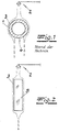
- Fig. 1 the flowed through by a cooling medium cross tube 1 of a cross tube gas cooler is shown, which is used according to the prior art for cooling coke oven gases.
- a sprinkler 2 With the help of a sprinkler 2 is a sprinkling of the cross tube 1 with water, so that one of the geometry of the cross tube 1 corresponding water film 3 is formed. This tears in the lower region of the cross tube 1 and therefore does not completely surround the cross tube 1.
- the cross tube bottom 4 is not wetted by the water film 3, and it comes there due to the condensation of ingredients contained in the coke oven gas, in particular tar or naphthalene, to a contamination of the cross tube. 1
- FIG. 2 shows a detail of the coke oven gas cooler according to the invention, in which the heat exchanger elements are designed as cooling plates 5.
- the cooling plates 5 are aligned vertically and can be flowed through by the cooling medium.
- the water film 3 formed by the irrigation by means of the sprinkler 2 wets completely due to the favorable plate geometry, the gas-side heat transfer surfaces, so that the coke oven gas, z. B. removed by condensation, excreted ingredients with the water film 3 and do not pollute the heat transfer surfaces.
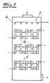
- the gas cooler for coke oven gas containing condensing ingredients with a gas channel 6 through which coke oven gas flows, heat exchanger elements within the gas channel 6 through which a cooling medium flows, and a sprinkler 2 above the heat exchanger elements, wherein the gas side heat exchanger surface of the heat exchanger elements is wetted with water, which is supplied by the sprinkler 2.
- the heat exchanger elements are designed as cooling plates 5, which can be traversed by the cooling medium and are combined with channel-forming spacers 7 to form at least one heat exchanger package.
- the heat exchanger packages are arranged with a vertical orientation of the cooling plates 5 in the gas channel 6, wherein the gas channels formed by the spacers 7 are acted on the upper side by the exiting from the sprinkler 2 water and flows through the coke oven gas.
- the heat exchanger packages can be used laterally as an exchange unit in the gas channel 6. In the example shown in FIG. 3, the gas channel 6 is vertically aligned.
Landscapes
- Engineering & Computer Science (AREA)
- Chemical & Material Sciences (AREA)
- Mechanical Engineering (AREA)
- General Engineering & Computer Science (AREA)
- Combustion & Propulsion (AREA)
- Physics & Mathematics (AREA)
- Thermal Sciences (AREA)
- Organic Chemistry (AREA)
- Oil, Petroleum & Natural Gas (AREA)
- Chemical Kinetics & Catalysis (AREA)
- General Chemical & Material Sciences (AREA)
- Materials Engineering (AREA)
- Heat-Exchange Devices With Radiators And Conduit Assemblies (AREA)
- Industrial Gases (AREA)
- Coke Industry (AREA)
- Ultra Sonic Daignosis Equipment (AREA)
- Electrophonic Musical Instruments (AREA)
Description
- Die Erfindung betrifft einen Gaskühler für Koksofengas, das kondensierende Inhaltsstoffe enthält, mit
einem von Koksofengas durchströmten Gaskanal,
von einem Kühlmedium durchströmten Wärmetauscherelementen innerhalb des Gaskanals und
einer Berieselungsvorrichtung oberhalb der Wärmetauscherelemente,
wobei die gasseitige Wärmetauscherfläche der Wärmetauscherelemente mit Flüssigkeit benetzt ist, die durch die Berieselungsvorrichtung zugeführt wird. - Nach dem Stand der Technik werden zur Kühlung von Koksofengas Querrohrgaskühler eingesetzt. Beim Betrieb solcher Kühler besteht das Problem, dass im Koksofengas enthaltene Inhaltsstoffe, insbesondere Teer oder Naphthalin, kondensieren, sich an den gasseitigen Wärmetauscherflächen ablagern und damit die Wärmeübertragung verschlechtern. Zur Reduzierung gasseitiger Ablagerungen werden die gasseitigen Wärmeübertragungsflächen des Querrohrgaskühlers mit Wasser berieselt, so dass sich auf den Flächen ein Wasserfilm ausbildet, der aus dem Koksofengas kondensierende Inhaltsstoffe abtransportiert. Die beschriebene Vorrichtung weist jedoch mehrere Nachteile auf. Die Berieselung von Querrohren gelingt nicht vollständig, da der sich auf der gasseitigen Wärmeübertragungsfläche ausbildende Wasserfilm im unteren Bereich der Querrohre aufreißt und das Wasser von dort aus abtropft oder abfließt. Dadurch liegt an der Unterseite der Querrohre kein geschlossener Wasserfilm vor, der einen ablagerungsfreien Abtransport ausgeschiedener Inhaltsstoffe erlaubt. Im Betrieb beobachtet man regelmäßig eine Verschmutzung an der Unterseite der Querrohre. Die erforderliche Reinigung der Querrohre ist aufwändig und führt zu einem Stillstand des Kühlers während des gesamten Reinigungsvorganges. Bei einer starken Verschmutzung der Rohre, welche durch Reinigungsvorgänge nicht entfernt werden kann, müssen die Rohre mit großem Aufwand aus dem Gaskanal entfernt und durch neue Rohre ersetzt werden. Dies verursacht hohe Kosten und ist ebenfalls mit einer langen Stillstandszeit des Kühlers verbunden.
- Ebenfalls bekannt aus dem Stand der Technik und offenbart in der WO 85/03339 ist ein Gaskühler mit als Külplatten ausgebildeten Wärmetauscherelementen.
- Der Erfindung liegt die Aufgabe zugrunde, einen Koksofengaskühler mit den eingangs beschriebenen Merkmalen anzugeben, der nur eine geringe Verschmutzungsneigung aufweist, eine schnelle Reinigung erlaubt und im seltenen Falle einer nicht durch Reinigung entfernbaren Verschmutzung einen schnellen Austausch der Wärmetauscherelemente ermöglicht.
- Erfindungsgemäß wird die Aufgabe durch die Kennzeichnenden Merkmale des Anspruchs 1 gelöst.
- Diese Lösung hat gegenüber dem Stand der Technik deutliche Vorteile. Die Berieselung der Kühlplatten mit Wasser hat aufgrund der günstigen Geometrie einen geschlossenen Wasserfilm auf den gasseitigen Wärmeübertragungsflächen zur Folge, der bis zum unteren Ende der Kühlplatten nicht aufreißt und daher die Kühlplatten vollständig benetzt. Dadurch wird die Ablagerung von ausgeschiedenen Inhaltsstoffen an den Wärmeübertragungsflächen wesentlich verringert.
- Das Wärmetauscherpaket kann in einem vertikalen Abschnitt des Gaskanals angeordnet sein, so dass das Koksofengas das Wärmetauscherpaket im Gleich- oder Gegenstrom zu dem an den Wärmetauscherflächen ablaufenden Flüssigkeitsfilm durchströmt.
- Alternativ kann das Wärmetauscherpaket in einem horizontalen Abschnitt des Gaskanals angeordnet sein, so dass das Koksofengas das Wärmetauscherpaket im Querstrom zu dem an den Wärmetauscherflächen ablaufenden Flüssigkeitsfilm durchströmt.
- Zusätzlich ist das Wärmetauscherpaket als Austauscheinheit seitlich in den Gaskanal einsetzbar. Dies hat weitere beachtliche Vorteile zur Folge. Die Reinigung des Wärmetauscherpakets verursacht nur einen geringen Aufwand, da dieses zur Reinigung aus dem Koksofengaskühler entfernt werden kann und dann besser zugänglich ist. Es ist auch möglich, das verschmutzte Wärmetauscherpaket gegen ein unverschmutztes Wärmetauscherpaket auszutauschen und nach erfolgter Reinigung erst bei der nächsten erforderlichen Reinigungsprozedur wieder einzusetzen. Hierdurch wird die durch eine Reinigung des Wärmetauscherpakets hervorgerufene Dauer des Stillstands des Koksofengaskühlers deutlich reduziert. Weiterhin ist im Falle einer sehr selten auftretenden z.B. durch eine Betriebsstörung der Berieselungsvorrichtung hervorgerufenen, starken Verschmutzung der Wärmeübertragungsflächen, welche durch Reinigungsvorgänge nicht entfernt kann, ein sehr leichter Ersatz des Wärmtauscherpakets möglich, der ebenfalls vergleichsweise niedrige Kosten verursacht und nur eine kurze Stillstandszeit zur Folge hat.
- Die Berieselungsvorrichtung ist vorzugsweise fest in dem Gaskanal installiert.
- Im Folgenden wird die Erfindung anhand einer lediglich ein Ausführungsbeispiel darstellenden Zeichnung erläutert. Es zeigen schematisch:
- Fig. 1
- einen Querschnitt durch ein Querrohr eines Querrohrgaskühlers, welcher nach dem Stand der Technik zur Kühlung von Koksofengasen eingesetzt wird,
- Fig. 2
- einen Ausschnitt aus dem erfindungsgemäßen Koksofengaskühler,
- Fig. 3
- eine Gesamtdarstellung des erfindungsgemäßen Koksofengaskühlers mit mehrfacher Anordnung der Wärme- tauscherpakete in einem vertikal ausgerichteten Gaskanal.
- In Fig. 1 ist das von einem Kühlmedium durchströmte Querrohr 1 eines Querrohrgaskühlers dargestellt, welcher nach dem Stand der Technik zur Kühlung von Koksofengasen Verwendung findet. Mit Hilfe einer Berieselungsvorrichtung 2 erfolgt eine Berieselung des Querrohrs 1 mit Wasser, so dass sich ein der Geometrie des Querrohrs 1 entsprechender Wasserfilm 3 ausbildet. Dieser reißt im unteren Bereich des Querrohrs 1 auf und umschließt daher das Querrohr 1 nicht vollständig. Die Querrohrunterseite 4 ist nicht vom Wasserfilm 3 benetzt, und es kommt dort aufgrund der Kondensation von im Koksofengas enthaltenen Inhaltsstoffen, insbesondere Teer oder Naphthalin, zu einer Verschmutzung des Querrohrs 1.
- Fig. 2 zeigt einen Ausschnitt aus dem erfindungsgemäßen Koksofengaskühler, bei dem die Wärmetauscherelemente als Kühlplatten 5 ausgebildet sind. Die Kühlplatten 5 sind vertikal ausgerichtet und von dem Kühlmedium durchströmbar. Der sich durch die Berieselung mittels der Berieselungsvorrichtung 2 bildende Wasserfilm 3 benetzt aufgrund der günstigen Plattengeometrie die gasseitigen Wärmeübertragungsflächen vollständig, so dass die aus dem Koksofengas, z. B. durch Kondensation, ausgeschiedenen Inhaltsstoffe mit dem Wasserfilm 3 abtransportiert werden und die Wärmeübertragungsflächen nicht verschmutzen.
- Fig. 3 zeigt die vollständige Darstellung des Gaskühlers für Koksofengas, das kondensierende Inhaltsstoffe enthält, mit einem von Koksofengas durchströmten Gaskanal 6, von einem Kühlmedium durchströmten Wärmetauscherelementen innerhalb des Gaskanals 6 und einer Berieselungsvorrichtung 2 oberhalb der Wärmetauscherelemente, wobei die gasseitige Wärmetauscherfläche der Wärmetauscherelemente mit Wasser benetzt ist, das durch die Berieselungsvorrichtung 2 zugeführt wird. Erfindungsgemäß sind die Wärmetauscherelemente als Kühlplatten 5 ausgebildet, die von dem Kühlmedium durchströmbar sind und mit kanalbildenden Abstandshaltern 7 zu mindestens einem Wärmetauscherpaket zusammengefasst sind. Die Wärmetauscherpakete sind mit vertikaler Ausrichtung der Kühlplatten 5 im Gaskanal 6 angeordnet, wobei die von den Abstandshaltern 7 gebildeten Gaskanäle oberseitig von dem aus der Berieselungsvorrichtung 2 austretenden Wasser beaufschlagt und von dem Koksofengas durchströmt sind. Die Wärmetauscherpakete sind als Austauscheinheit seitlich in den Gaskanal 6 einsetzbar. In dem in Fig. 3 dargestellten Beispiel ist der Gaskanal 6 vertikal ausgerichtet.
Claims (4)
- Gaskühler für Koksofengas, das kondensierende Inhaltsstoffe enthält, mit
einem von Koksofengas durchströmten Gaskanal (6) und
von einem Kühlmedium durchströmten Kühlplatten (5), die mit kanalbildenden Abstandshaltern (7) zu mindestens einem Wärmetauscherpaket zusammengefasst sind,
wobei das Wärmetauscherpaket mit vertikaler Ausrichtung der Kühlplatten (5) im Gaskanal (6) angeordnet ist sowie oberhalb des Wärmetauscherpaketes eine Berieselungsvorrichtung (2) vorgesehen ist, dadurch gekenn-zeichnet, dass die von den Abstandshaltern (7) gebildeten Gaskanäle von dem Koksofengas durchströmt sowie von der aus der Berieselungsvorrichtung (2) austretenden Flüssigkeit beaufschlagt sind,
so dass die gasseitige Wärmetauscherfläche der Kühlplatten (5) mit Flüssigkeit benetzt ist und sich auf der Wärmetauscherfläche ein Flüssigkeitsfilm bildet, der aus dem Koksofengas kondensierende Inhaltsstoffe abtransportiert, und
dass das Wärmetauscherpaket als Austauscheinheit seitlich in den Gaskanal (6) einsetzbar ist. - Gaskühler nach Anspruch 1, dadurch gekennzeichnet, dass das Wärmetauscherpaket in einem vertikalen Abschnitt des Gaskanals (6) angeordnet ist und das Koksofengas das Wärmetauscherpaket im Gleich- oder Gegenstrom zu dem an den Wärmetauscherflächen ablaufenden Flüssigkeitsfilm durchströmt.
- Gaskühler nach Anspruch 1, dadurch gekennzeichnet, dass das Wärmetauscherpaket in einem horizontalen Abschnitt des Gaskanals (6) angeordnet ist und das Koksofengas das Wärmetauscherpaket im Querstrom zu dem an den Wärmetauscherflächen ablaufenden Flüssigkeitsfilm durchströmt.
- Gaskühler nach Anspruch 1 bis 3, dadurch gekennzeichnet, dass die Berieselungsvorrichtung (2) fest in dem Gaskanal (6) installiert ist.
Priority Applications (1)
| Application Number | Priority Date | Filing Date | Title |
|---|---|---|---|
| SI200330379T SI1570026T1 (sl) | 2002-12-11 | 2003-08-02 | Plinski hladilnik za pec za koks |
Applications Claiming Priority (3)
| Application Number | Priority Date | Filing Date | Title |
|---|---|---|---|
| DE10258066A DE10258066A1 (de) | 2002-12-11 | 2002-12-11 | Koksofengaskühler |
| DE10258066 | 2002-12-11 | ||
| PCT/EP2003/008580 WO2004053023A1 (de) | 2002-12-11 | 2003-08-02 | Koksofengaskühler |
Publications (3)
| Publication Number | Publication Date |
|---|---|
| EP1570026A1 EP1570026A1 (de) | 2005-09-07 |
| EP1570026B1 true EP1570026B1 (de) | 2006-05-24 |
| EP1570026B8 EP1570026B8 (de) | 2006-09-27 |
Family
ID=32336231
Family Applications (1)
| Application Number | Title | Priority Date | Filing Date |
|---|---|---|---|
| EP03812575A Expired - Lifetime EP1570026B8 (de) | 2002-12-11 | 2003-08-02 | Koksofengaskühler |
Country Status (17)
| Country | Link |
|---|---|
| US (1) | US7566049B2 (de) |
| EP (1) | EP1570026B8 (de) |
| JP (1) | JP4180055B2 (de) |
| KR (1) | KR100996481B1 (de) |
| CN (1) | CN100347270C (de) |
| AT (1) | ATE327300T1 (de) |
| AU (1) | AU2003255357A1 (de) |
| BR (1) | BR0317112B1 (de) |
| CA (1) | CA2509368C (de) |
| DE (2) | DE10258066A1 (de) |
| ES (1) | ES2266920T3 (de) |
| MX (1) | MXPA05006217A (de) |
| PL (1) | PL206333B1 (de) |
| PT (1) | PT1570026E (de) |
| TW (1) | TWI241341B (de) |
| WO (1) | WO2004053023A1 (de) |
| ZA (1) | ZA200504755B (de) |
Families Citing this family (16)
| Publication number | Priority date | Publication date | Assignee | Title |
|---|---|---|---|---|
| CN101235323B (zh) * | 2008-02-01 | 2011-04-20 | 丹东市承天新能源开发有限公司 | 水幕喷淋净化器 |
| CN101619894B (zh) * | 2008-06-30 | 2012-05-30 | 上海梅山钢铁股份有限公司 | 一种焦炉荒煤气二次冷凝余热回收装置 |
| CN101922889B (zh) * | 2009-06-12 | 2012-07-11 | 斯必克斯冷却技术(北京)有限公司 | 空气冷凝器的冲洗系统 |
| DE102011103625A1 (de) * | 2010-06-18 | 2012-06-14 | Heinz-Dieter Hombücher | Vorrichtung zur Rückkühlung von Wärmeträgern und Arbeitsstoffen aus der Kältetechnik und Flüssigkeitskühlern sowie Kälterückgewinnung in der Lüftungstechnik |
| CN103805292B (zh) * | 2012-11-13 | 2016-01-13 | 山东汉菱电气有限公司 | 用于煤气净化脱硫除油脱水的弱碱源自洁换热器 |
| CN103353243A (zh) * | 2013-07-03 | 2013-10-16 | 无锡宇吉科技有限公司 | 一种喷淋式换热器 |
| CN103697730B (zh) * | 2014-01-17 | 2016-01-06 | 中钢集团天澄环保科技股份有限公司 | 一种高温烟气快速冷却器 |
| DE102014213201A1 (de) * | 2014-07-08 | 2016-01-14 | Bayer Technology Services Gmbh | Berieselungssystem für Behälter |
| CN105180667B (zh) * | 2015-09-30 | 2017-12-05 | 上海宝钢节能环保技术有限公司 | 一种异型水夹套荒煤气显热回收装置 |
| CN105925322B (zh) * | 2016-04-28 | 2018-12-28 | 中国重型机械研究院股份公司 | 一种直立折线型高温热解气冷却及余热回收装置 |
| CN107413778A (zh) * | 2017-04-27 | 2017-12-01 | 唐山钢铁集团有限责任公司 | 一种降低焦化终冷器阻力的清洗方法 |
| CN107937042B (zh) * | 2017-12-22 | 2024-01-30 | 中冶焦耐(大连)工程技术有限公司 | 一种复合急冷塔 |
| CN108507377A (zh) * | 2018-02-26 | 2018-09-07 | 中冶华天工程技术有限公司 | 一种煤气减温减压装置 |
| CN110452715B (zh) * | 2019-09-04 | 2024-08-13 | 华泰永创(北京)科技股份有限公司 | 上升管蒸发器、焦化系统及上升管蒸发器的冷却方法 |
| CN112498310B (zh) * | 2021-01-06 | 2022-02-08 | 郑州铁路职业技术学院 | 一种可回收式铁路机车用液压制动快速冷却装置 |
| CN112985163B (zh) * | 2021-02-03 | 2022-06-21 | 广东韶钢松山股份有限公司 | 一种初冷器的清洗方法及初冷器净化系统 |
Family Cites Families (8)
| Publication number | Priority date | Publication date | Assignee | Title |
|---|---|---|---|---|
| US899201A (en) * | 1906-03-23 | 1908-09-22 | Gary Braybrook | Beer-faucet. |
| US889201A (en) * | 1906-12-21 | 1908-06-02 | John Calhoun Clark | Vapor-condenser. |
| DE1028579B (de) * | 1952-08-04 | 1958-04-24 | Still Fa Carl | Verfahren zur Gewinnung von Pyridin aus schwefelsaeurehaltiger Ammoniaksaettigerfluessigkeit |
| BE785340Q (fr) * | 1971-02-15 | 1972-10-16 | Kohlenimport Und Grosshandelsg | Procede de decomposition et d'elimination par rincage des encroutementsscorifies formes sur les surfaces de chauffe cote foyerdes chaudieres |
| US4340572A (en) * | 1978-05-19 | 1982-07-20 | Woodside Construction, Inc. | Process for recovering heat from stack or flue gas |
| US4614229A (en) * | 1983-06-20 | 1986-09-30 | Exxon Research & Engineering Co. | Method and apparatus for efficient recovery of heat from hot gases that tend to foul heat exchanger tubes |
| SE8400275L (sv) * | 1984-01-20 | 1985-07-21 | Celleco Ab | Anordning for vermeatervinning ur rokgaser |
| JP2580991B2 (ja) * | 1993-12-29 | 1997-02-12 | 石川島播磨重工業株式会社 | 被冷却水の冷却方法及び冷水塔 |
-
2002
- 2002-12-11 DE DE10258066A patent/DE10258066A1/de not_active Withdrawn
-
2003
- 2003-08-02 CN CNB038258013A patent/CN100347270C/zh not_active Expired - Fee Related
- 2003-08-02 PT PT03812575T patent/PT1570026E/pt unknown
- 2003-08-02 US US10/538,272 patent/US7566049B2/en not_active Expired - Fee Related
- 2003-08-02 WO PCT/EP2003/008580 patent/WO2004053023A1/de not_active Ceased
- 2003-08-02 JP JP2004557852A patent/JP4180055B2/ja not_active Expired - Fee Related
- 2003-08-02 ZA ZA200504755A patent/ZA200504755B/en unknown
- 2003-08-02 KR KR1020057010720A patent/KR100996481B1/ko not_active Expired - Fee Related
- 2003-08-02 CA CA2509368A patent/CA2509368C/en not_active Expired - Fee Related
- 2003-08-02 DE DE50303517T patent/DE50303517D1/de not_active Expired - Lifetime
- 2003-08-02 BR BRPI0317112-4A patent/BR0317112B1/pt not_active IP Right Cessation
- 2003-08-02 EP EP03812575A patent/EP1570026B8/de not_active Expired - Lifetime
- 2003-08-02 AT AT03812575T patent/ATE327300T1/de active
- 2003-08-02 MX MXPA05006217A patent/MXPA05006217A/es active IP Right Grant
- 2003-08-02 AU AU2003255357A patent/AU2003255357A1/en not_active Abandoned
- 2003-08-02 ES ES03812575T patent/ES2266920T3/es not_active Expired - Lifetime
- 2003-08-02 PL PL375722A patent/PL206333B1/pl unknown
- 2003-09-25 TW TW092126475A patent/TWI241341B/zh not_active IP Right Cessation
Also Published As
| Publication number | Publication date |
|---|---|
| DE50303517D1 (de) | 2006-06-29 |
| US7566049B2 (en) | 2009-07-28 |
| CA2509368C (en) | 2010-07-13 |
| US20060249861A1 (en) | 2006-11-09 |
| ZA200504755B (en) | 2006-09-27 |
| CN100347270C (zh) | 2007-11-07 |
| EP1570026A1 (de) | 2005-09-07 |
| JP2006509852A (ja) | 2006-03-23 |
| PL375722A1 (en) | 2005-12-12 |
| BR0317112B1 (pt) | 2013-02-19 |
| WO2004053023A1 (de) | 2004-06-24 |
| EP1570026B8 (de) | 2006-09-27 |
| ES2266920T3 (es) | 2007-03-01 |
| DE10258066A1 (de) | 2004-06-24 |
| MXPA05006217A (es) | 2005-09-08 |
| KR100996481B1 (ko) | 2010-11-24 |
| ATE327300T1 (de) | 2006-06-15 |
| AU2003255357A1 (en) | 2004-06-30 |
| TWI241341B (en) | 2005-10-11 |
| CA2509368A1 (en) | 2005-06-09 |
| PL206333B1 (pl) | 2010-07-30 |
| KR20050085595A (ko) | 2005-08-29 |
| TW200413513A (en) | 2004-08-01 |
| CN1720315A (zh) | 2006-01-11 |
| JP4180055B2 (ja) | 2008-11-12 |
| BR0317112A (pt) | 2005-10-25 |
| PT1570026E (pt) | 2006-09-29 |
Similar Documents
| Publication | Publication Date | Title |
|---|---|---|
| EP1570026B1 (de) | Koksofengask hler | |
| DE102008048405B3 (de) | Rohrbündel-Wärmetauscher zur Regelung eines breiten Leistungsbereiches | |
| EP1703244B1 (de) | Blockwärmetauscher für staubhaltige Rauchgase | |
| DE2638468C2 (de) | ||
| DE19513691A1 (de) | Vorrichtung zum Aufbringen dünner Schichten auf ein Substrat | |
| EP0742039B1 (de) | Vorrichtung zur Reinigung von Gasen, wie Abgasen und/oder Synthesegasen | |
| EP2258462A1 (de) | Wäscherturm und zugehörige Rauchgasreinigungsvorrichtung | |
| EP3102900B1 (de) | Zum wärme- und/oder stoffaustausch geeigneter plattenapparat | |
| EP1551588B1 (de) | Reinigungsvorrichtung zur reinigung von prozessgas einer reflowlötanlage | |
| EP0619466B1 (de) | Dampfkondensator | |
| DE3127039A1 (de) | "verfahren und waermetauscher zum sieden von fluessiggas" | |
| DE102009038836A1 (de) | Plattenwärmeübertrager | |
| DD210966A1 (de) | Rekuperativer waermeuebertrager | |
| DE2946433A1 (de) | Vorrichtung zum regenerieren von waschfluessigkeit und verfahren zu deren betrieb | |
| EP1890099A1 (de) | Rücklaufkondensator | |
| DE102010041289A1 (de) | Stoff- und Wärmeaustauscherplatte sowie ein Stoff- und Wärmeaustauschreaktor mit einer solchen Stoff- und Wärmeaustauscherplatte | |
| EP3209452A1 (de) | Verfahren zur herstellung eines plattenwärmetauschers durch zwei schweissungen und entsprechender plattenwärmetauscher | |
| DE3152372T1 (de) | A method and an apparatus for the treatment of a contaminated gas of elevated temperature | |
| DE959917C (de) | Gleich- oder Gegenstrom-Waermetauscher in Blockform | |
| EP0856714A2 (de) | Verfahren und Vorrichtung zur Entfernung von kondensierbaren Komponenten aus Gasen und/oder Gasgemischen | |
| DE60100604T2 (de) | Wärmerückgewinnungsvorrichtung und Verfahren zur Minimierung der Verschmutzung in einer Wärmerückgewinnungsvorrichtung | |
| EP1736229B1 (de) | Vorrichtung zur Kondensatabscheidung | |
| DE4344480A1 (de) | Flexibler Wärmeübertrager für die Wärmerückgewinnung aus verschmutzter Abluft und Abgasen oder die Erwärmung von Gasen | |
| DE202019103879U1 (de) | Vorrichtung zur fraktionierten Gasprobenahme | |
| DE19729710A1 (de) | Vorrichtung zum Eindicken von Flüssigkeiten |
Legal Events
| Date | Code | Title | Description |
|---|---|---|---|
| PUAI | Public reference made under article 153(3) epc to a published international application that has entered the european phase |
Free format text: ORIGINAL CODE: 0009012 |
|
| 17P | Request for examination filed |
Effective date: 20050608 |
|
| AK | Designated contracting states |
Kind code of ref document: A1 Designated state(s): AT BE BG CH CY CZ DE DK EE ES FI FR GB GR HU IE IT LI LU MC NL PT RO SE SI SK TR |
|
| AX | Request for extension of the european patent |
Extension state: AL LT LV MK |
|
| GRAP | Despatch of communication of intention to grant a patent |
Free format text: ORIGINAL CODE: EPIDOSNIGR1 |
|
| GRAS | Grant fee paid |
Free format text: ORIGINAL CODE: EPIDOSNIGR3 |
|
| DAX | Request for extension of the european patent (deleted) | ||
| GRAA | (expected) grant |
Free format text: ORIGINAL CODE: 0009210 |
|
| AK | Designated contracting states |
Kind code of ref document: B1 Designated state(s): AT BE BG CH CY CZ DE DK EE ES FI FR GB GR HU IE IT LI LU MC NL PT RO SE SI SK TR |
|
| PG25 | Lapsed in a contracting state [announced via postgrant information from national office to epo] |
Ref country code: IE Free format text: LAPSE BECAUSE OF FAILURE TO SUBMIT A TRANSLATION OF THE DESCRIPTION OR TO PAY THE FEE WITHIN THE PRESCRIBED TIME-LIMIT Effective date: 20060524 |
|
| REG | Reference to a national code |
Ref country code: GB Ref legal event code: FG4D Free format text: NOT ENGLISH |
|
| REG | Reference to a national code |
Ref country code: CH Ref legal event code: EP |
|
| REG | Reference to a national code |
Ref country code: IE Ref legal event code: FG4D Free format text: LANGUAGE OF EP DOCUMENT: GERMAN |
|
| REF | Corresponds to: |
Ref document number: 50303517 Country of ref document: DE Date of ref document: 20060629 Kind code of ref document: P |
|
| REG | Reference to a national code |
Ref country code: RO Ref legal event code: EPE |
|
| PG25 | Lapsed in a contracting state [announced via postgrant information from national office to epo] |
Ref country code: DK Free format text: LAPSE BECAUSE OF FAILURE TO SUBMIT A TRANSLATION OF THE DESCRIPTION OR TO PAY THE FEE WITHIN THE PRESCRIBED TIME-LIMIT Effective date: 20060824 |
|
| PG25 | Lapsed in a contracting state [announced via postgrant information from national office to epo] |
Ref country code: MC Free format text: LAPSE BECAUSE OF NON-PAYMENT OF DUE FEES Effective date: 20060831 |
|
| REG | Reference to a national code |
Ref country code: SE Ref legal event code: TRGR |
|
| REG | Reference to a national code |
Ref country code: GR Ref legal event code: EP Ref document number: 20060402591 Country of ref document: GR |
|
| REG | Reference to a national code |
Ref country code: PT Ref legal event code: SC4A Effective date: 20060810 |
|
| GBT | Gb: translation of ep patent filed (gb section 77(6)(a)/1977) |
Effective date: 20060911 |
|
| REG | Reference to a national code |
Ref country code: HU Ref legal event code: AG4A Ref document number: E000623 Country of ref document: HU |
|
| REG | Reference to a national code |
Ref country code: IE Ref legal event code: FD4D |
|
| ET | Fr: translation filed | ||
| REG | Reference to a national code |
Ref country code: ES Ref legal event code: FG2A Ref document number: 2266920 Country of ref document: ES Kind code of ref document: T3 |
|
| PLBE | No opposition filed within time limit |
Free format text: ORIGINAL CODE: 0009261 |
|
| STAA | Information on the status of an ep patent application or granted ep patent |
Free format text: STATUS: NO OPPOSITION FILED WITHIN TIME LIMIT |
|
| 26N | No opposition filed |
Effective date: 20070227 |
|
| REG | Reference to a national code |
Ref country code: CH Ref legal event code: PL |
|
| PG25 | Lapsed in a contracting state [announced via postgrant information from national office to epo] |
Ref country code: LI Free format text: LAPSE BECAUSE OF NON-PAYMENT OF DUE FEES Effective date: 20070831 Ref country code: CH Free format text: LAPSE BECAUSE OF NON-PAYMENT OF DUE FEES Effective date: 20070831 |
|
| PG25 | Lapsed in a contracting state [announced via postgrant information from national office to epo] |
Ref country code: EE Free format text: LAPSE BECAUSE OF FAILURE TO SUBMIT A TRANSLATION OF THE DESCRIPTION OR TO PAY THE FEE WITHIN THE PRESCRIBED TIME-LIMIT Effective date: 20060524 |
|
| PG25 | Lapsed in a contracting state [announced via postgrant information from national office to epo] |
Ref country code: CY Free format text: LAPSE BECAUSE OF FAILURE TO SUBMIT A TRANSLATION OF THE DESCRIPTION OR TO PAY THE FEE WITHIN THE PRESCRIBED TIME-LIMIT Effective date: 20060524 |
|
| REG | Reference to a national code |
Ref country code: DE Ref legal event code: R082 Ref document number: 50303517 Country of ref document: DE Representative=s name: RAINER ALBRECHT, DE |
|
| REG | Reference to a national code |
Ref country code: DE Ref legal event code: R081 Ref document number: 50303517 Country of ref document: DE Owner name: THYSSENKRUPP UHDE GMBH, DE Free format text: FORMER OWNER: UHDE GMBH, 44141 DORTMUND, DE Effective date: 20120627 Ref country code: DE Ref legal event code: R082 Ref document number: 50303517 Country of ref document: DE Representative=s name: ALBRECHT, RAINER, DIPL.-ING. DR.-ING., DE Effective date: 20120627 Ref country code: DE Ref legal event code: R081 Ref document number: 50303517 Country of ref document: DE Owner name: THYSSENKRUPP INDUSTRIAL SOLUTIONS AG, DE Free format text: FORMER OWNER: UHDE GMBH, 44141 DORTMUND, DE Effective date: 20120627 |
|
| PGFP | Annual fee paid to national office [announced via postgrant information from national office to epo] |
Ref country code: LU Payment date: 20140822 Year of fee payment: 12 |
|
| PGFP | Annual fee paid to national office [announced via postgrant information from national office to epo] |
Ref country code: FI Payment date: 20140813 Year of fee payment: 12 Ref country code: RO Payment date: 20140729 Year of fee payment: 12 Ref country code: CZ Payment date: 20140728 Year of fee payment: 12 Ref country code: GR Payment date: 20140827 Year of fee payment: 12 Ref country code: BG Payment date: 20140814 Year of fee payment: 12 |
|
| PGFP | Annual fee paid to national office [announced via postgrant information from national office to epo] |
Ref country code: SK Payment date: 20140731 Year of fee payment: 12 Ref country code: SI Payment date: 20140728 Year of fee payment: 12 Ref country code: FR Payment date: 20140821 Year of fee payment: 12 Ref country code: TR Payment date: 20140722 Year of fee payment: 12 Ref country code: HU Payment date: 20140821 Year of fee payment: 12 |
|
| PGFP | Annual fee paid to national office [announced via postgrant information from national office to epo] |
Ref country code: IT Payment date: 20140827 Year of fee payment: 12 Ref country code: PT Payment date: 20140203 Year of fee payment: 12 |
|
| PGFP | Annual fee paid to national office [announced via postgrant information from national office to epo] |
Ref country code: BE Payment date: 20140820 Year of fee payment: 12 |
|
| REG | Reference to a national code |
Ref country code: DE Ref legal event code: R082 Ref document number: 50303517 Country of ref document: DE Representative=s name: ALBRECHT, RAINER, DIPL.-ING. DR.-ING., DE Ref country code: DE Ref legal event code: R081 Ref document number: 50303517 Country of ref document: DE Owner name: THYSSENKRUPP INDUSTRIAL SOLUTIONS AG, DE Free format text: FORMER OWNER: THYSSENKRUPP UHDE GMBH, 44141 DORTMUND, DE |
|
| REG | Reference to a national code |
Ref country code: PT Ref legal event code: MM4A Free format text: LAPSE DUE TO NON-PAYMENT OF FEES Effective date: 20160202 |
|
| PG25 | Lapsed in a contracting state [announced via postgrant information from national office to epo] |
Ref country code: LU Free format text: LAPSE BECAUSE OF NON-PAYMENT OF DUE FEES Effective date: 20150802 |
|
| PG25 | Lapsed in a contracting state [announced via postgrant information from national office to epo] |
Ref country code: BG Free format text: LAPSE BECAUSE OF NON-PAYMENT OF DUE FEES Effective date: 20160331 Ref country code: SK Free format text: LAPSE BECAUSE OF NON-PAYMENT OF DUE FEES Effective date: 20150802 Ref country code: CZ Free format text: LAPSE BECAUSE OF NON-PAYMENT OF DUE FEES Effective date: 20150802 Ref country code: IT Free format text: LAPSE BECAUSE OF NON-PAYMENT OF DUE FEES Effective date: 20150802 |
|
| REG | Reference to a national code |
Ref country code: SI Ref legal event code: KO00 Effective date: 20160331 |
|
| REG | Reference to a national code |
Ref country code: SK Ref legal event code: MM4A Ref document number: E 896 Country of ref document: SK Effective date: 20150802 |
|
| PG25 | Lapsed in a contracting state [announced via postgrant information from national office to epo] |
Ref country code: HU Free format text: LAPSE BECAUSE OF NON-PAYMENT OF DUE FEES Effective date: 20150803 Ref country code: RO Free format text: LAPSE BECAUSE OF NON-PAYMENT OF DUE FEES Effective date: 20150802 Ref country code: SI Free format text: LAPSE BECAUSE OF NON-PAYMENT OF DUE FEES Effective date: 20150803 Ref country code: GR Free format text: LAPSE BECAUSE OF NON-PAYMENT OF DUE FEES Effective date: 20160303 Ref country code: PT Free format text: LAPSE BECAUSE OF NON-PAYMENT OF DUE FEES Effective date: 20160202 Ref country code: FI Free format text: LAPSE BECAUSE OF NON-PAYMENT OF DUE FEES Effective date: 20150802 |
|
| REG | Reference to a national code |
Ref country code: FR Ref legal event code: ST Effective date: 20160429 |
|
| REG | Reference to a national code |
Ref country code: GR Ref legal event code: ML Ref document number: 20060402591 Country of ref document: GR Effective date: 20160303 |
|
| PG25 | Lapsed in a contracting state [announced via postgrant information from national office to epo] |
Ref country code: FR Free format text: LAPSE BECAUSE OF NON-PAYMENT OF DUE FEES Effective date: 20150831 |
|
| PGFP | Annual fee paid to national office [announced via postgrant information from national office to epo] |
Ref country code: NL Payment date: 20160819 Year of fee payment: 14 |
|
| PGFP | Annual fee paid to national office [announced via postgrant information from national office to epo] |
Ref country code: GB Payment date: 20160819 Year of fee payment: 14 |
|
| PGFP | Annual fee paid to national office [announced via postgrant information from national office to epo] |
Ref country code: SE Payment date: 20160819 Year of fee payment: 14 Ref country code: AT Payment date: 20160822 Year of fee payment: 14 |
|
| PGFP | Annual fee paid to national office [announced via postgrant information from national office to epo] |
Ref country code: ES Payment date: 20160810 Year of fee payment: 14 |
|
| PG25 | Lapsed in a contracting state [announced via postgrant information from national office to epo] |
Ref country code: BE Free format text: LAPSE BECAUSE OF NON-PAYMENT OF DUE FEES Effective date: 20150831 |
|
| PG25 | Lapsed in a contracting state [announced via postgrant information from national office to epo] |
Ref country code: TR Free format text: LAPSE BECAUSE OF NON-PAYMENT OF DUE FEES Effective date: 20150802 |
|
| REG | Reference to a national code |
Ref country code: NL Ref legal event code: MM Effective date: 20170901 |
|
| REG | Reference to a national code |
Ref country code: AT Ref legal event code: MM01 Ref document number: 327300 Country of ref document: AT Kind code of ref document: T Effective date: 20170802 |
|
| GBPC | Gb: european patent ceased through non-payment of renewal fee |
Effective date: 20170802 |
|
| PG25 | Lapsed in a contracting state [announced via postgrant information from national office to epo] |
Ref country code: SE Free format text: LAPSE BECAUSE OF NON-PAYMENT OF DUE FEES Effective date: 20170803 |
|
| PG25 | Lapsed in a contracting state [announced via postgrant information from national office to epo] |
Ref country code: AT Free format text: LAPSE BECAUSE OF NON-PAYMENT OF DUE FEES Effective date: 20170802 |
|
| PG25 | Lapsed in a contracting state [announced via postgrant information from national office to epo] |
Ref country code: NL Free format text: LAPSE BECAUSE OF NON-PAYMENT OF DUE FEES Effective date: 20170901 |
|
| PG25 | Lapsed in a contracting state [announced via postgrant information from national office to epo] |
Ref country code: GB Free format text: LAPSE BECAUSE OF NON-PAYMENT OF DUE FEES Effective date: 20170802 |
|
| REG | Reference to a national code |
Ref country code: ES Ref legal event code: FD2A Effective date: 20181030 |
|
| PG25 | Lapsed in a contracting state [announced via postgrant information from national office to epo] |
Ref country code: ES Free format text: LAPSE BECAUSE OF NON-PAYMENT OF DUE FEES Effective date: 20170803 |
|
| REG | Reference to a national code |
Ref country code: DE Ref legal event code: R082 Ref document number: 50303517 Country of ref document: DE Representative=s name: ALBRECHT, RAINER, DIPL.-ING. DR.-ING., DE Ref country code: DE Ref legal event code: R081 Ref document number: 50303517 Country of ref document: DE Owner name: THYSSENKRUPP INDUSTRIAL SOLUTIONS AG, DE Free format text: FORMER OWNER: THYSSENKRUPP INDUSTRIAL SOLUTIONS AG, 45143 ESSEN, DE |
|
| PGFP | Annual fee paid to national office [announced via postgrant information from national office to epo] |
Ref country code: DE Payment date: 20190822 Year of fee payment: 17 |
|
| REG | Reference to a national code |
Ref country code: DE Ref legal event code: R119 Ref document number: 50303517 Country of ref document: DE |
|
| PG25 | Lapsed in a contracting state [announced via postgrant information from national office to epo] |
Ref country code: DE Free format text: LAPSE BECAUSE OF NON-PAYMENT OF DUE FEES Effective date: 20210302 |