EP1569849B1 - Machine de conditionnement sous blister - Google Patents
Machine de conditionnement sous blister Download PDFInfo
- Publication number
- EP1569849B1 EP1569849B1 EP04797922A EP04797922A EP1569849B1 EP 1569849 B1 EP1569849 B1 EP 1569849B1 EP 04797922 A EP04797922 A EP 04797922A EP 04797922 A EP04797922 A EP 04797922A EP 1569849 B1 EP1569849 B1 EP 1569849B1
- Authority
- EP
- European Patent Office
- Prior art keywords
- bottom foil
- foil
- packaging machine
- blister packaging
- station
- Prior art date
- Legal status (The legal status is an assumption and is not a legal conclusion. Google has not performed a legal analysis and makes no representation as to the accuracy of the status listed.)
- Expired - Lifetime
Links
- 238000004806 packaging method and process Methods 0.000 title claims description 18
- 239000011888 foil Substances 0.000 claims abstract description 68
- 238000007789 sealing Methods 0.000 claims abstract description 63
- 230000015572 biosynthetic process Effects 0.000 claims 1
- 230000032258 transport Effects 0.000 description 29
- 239000010408 film Substances 0.000 description 27
- 238000010586 diagram Methods 0.000 description 6
- 239000013039 cover film Substances 0.000 description 4
- 125000004122 cyclic group Chemical group 0.000 description 4
- 238000000034 method Methods 0.000 description 4
- 238000011144 upstream manufacturing Methods 0.000 description 2
- XAGFODPZIPBFFR-UHFFFAOYSA-N aluminium Chemical compound [Al] XAGFODPZIPBFFR-UHFFFAOYSA-N 0.000 description 1
- 229910052782 aluminium Inorganic materials 0.000 description 1
- 210000000080 chela (arthropods) Anatomy 0.000 description 1
- 238000000151 deposition Methods 0.000 description 1
- 238000010438 heat treatment Methods 0.000 description 1
- 230000001502 supplementing effect Effects 0.000 description 1
- 230000001360 synchronised effect Effects 0.000 description 1
Images


Classifications
-
- B—PERFORMING OPERATIONS; TRANSPORTING
- B65—CONVEYING; PACKING; STORING; HANDLING THIN OR FILAMENTARY MATERIAL
- B65B—MACHINES, APPARATUS OR DEVICES FOR, OR METHODS OF, PACKAGING ARTICLES OR MATERIALS; UNPACKING
- B65B57/00—Automatic control, checking, warning, or safety devices
- B65B57/02—Automatic control, checking, warning, or safety devices responsive to absence, presence, abnormal feed, or misplacement of binding or wrapping material, containers, or packages
- B65B57/08—Automatic control, checking, warning, or safety devices responsive to absence, presence, abnormal feed, or misplacement of binding or wrapping material, containers, or packages and operating to stop, or to control the speed of, the machine as a whole
-
- B—PERFORMING OPERATIONS; TRANSPORTING
- B65—CONVEYING; PACKING; STORING; HANDLING THIN OR FILAMENTARY MATERIAL
- B65B—MACHINES, APPARATUS OR DEVICES FOR, OR METHODS OF, PACKAGING ARTICLES OR MATERIALS; UNPACKING
- B65B9/00—Enclosing successive articles, or quantities of material, e.g. liquids or semiliquids, in flat, folded, or tubular webs of flexible sheet material; Subdividing filled flexible tubes to form packages
- B65B9/02—Enclosing successive articles, or quantities of material between opposed webs
- B65B9/04—Enclosing successive articles, or quantities of material between opposed webs one or both webs being formed with pockets for the reception of the articles, or of the quantities of material
Definitions
- the invention relates to a blister packaging machine with a filling station, with the products in cup-shaped depressions of a bottom sheet can be inserted, and a downstream sealing station, in which a supplied cover sheet on the bottom sheet to form a blister strip can be sealed, the cyclically operating sealing station a Intermittently operating first drive device is assigned, with which the bottom foil and the cover foil can be transported discontinuously through the sealing station.
- a machine is e.g. from EP.A.0 310 306.
- a blister packaging machine comprises a forming station, in which a plurality of cup-shaped depressions are inserted into a bottom foil, which can be made of plastic or aluminum, for example, into which a product, for example a pharmaceutical-grade tablet, is inserted in a downstream filling station.
- a product for example a pharmaceutical-grade tablet
- the bottom film is fed to a sealing station.
- a cover sheet is fed and onto the bottom sheet on the open side of the cup-shaped recesses hung up. By heat and pressure within the sealing station, the cover sheet is sealed tightly onto the bottom sheet, thereby enclosing the products in the cup-shaped depressions.
- the filling station In order to ensure precise feeding and depositing of the products in the cup-shaped depressions of the bottom foil, it is desirable to form the filling station in a stationary manner and to guide the bottom foil uniformly through the filling station at a constant speed.
- the sealing of the cover film in the subsequent sealing station also takes place continuously, for which purpose usually a rotating sealing roller is used, which can be tempered by means of a heating device to a predetermined desired temperature.
- the bottom film is conveyed together with the cover film at a constant transport speed through the sealing station, ie through the gap between the sealing roller and a counter-roller, wherein heat is transferred from the sealing roller to the film and connects them together.
- the heat transfer between the sealing roller and the films depends on their transport speed.
- the contact time between the sealing roller and the films is relatively low, so that only a small amount of heat can be introduced into the films. If too little heat is introduced into the film, there is a risk that the seal is incomplete and thus the tightness between the bottom film and the cover sheet is not given.
- the contact time between the sealing roller and the films is relatively large, so that a large amount of heat is introduced into the films, which involves the risk that the relatively heat-sensitive cover sheet is damaged. Also in this case, a reliable seal between the bottom sheet and the cover sheet is not guaranteed.
- a continuous sealing station is not desired, but a sealing station operating in cycles with sealing plates to be closed and opened, in which the heat transfer into the films and thus the sealing process can be set very precisely over the closing time of the sealing plates overall leads to a very uniform appearance of the seal.
- the blister band i. the bottom film with inserted products and sealed cover sheet
- a cyclically operating drive device for example in the form of pliers and pulled forward by a predetermined amount, whereupon the pliers opens and moves against the transport direction along the blister band and this in an upstream Seizes again section.
- This causes a transport movement and a standstill of the blister band constantly alternate.
- the bottom foil also experiences this intermittent movement, so that it is pulled cyclically through the filling station.
- the invention has for its object to provide a blister packaging machine of the type mentioned with a cyclically operating sealing station, which reliably enables the use of a powerful filling station.
- a second drive device for the bottom foil is arranged, by means of which the bottom foil is discontinuously transportable, wherein the drive movements of the first drive device and the second drive device are superimposed such that the bottom foil at the filling station, the is formed stationary, is transported at a constant speed.
- the invention is based on the basic idea of supplementing the cyclic or intermittent forward movement of the bottom foil as a result of the cyclically operating first drive device of the sealing station by a second drive device which acts on the bottom foil between the filling station and the sealing station and preferably upstream of the feeding of the cover foil this gives a discontinuous, controlled transport movement.
- the two drive movements as a result of the first drive device and the second drive device are matched to one another such that the resulting movement of the bottom foil in or at the filling station is a continuous preferential movement with a constant transport speed. In this way it is possible to fill the products in the cup-shaped depressions by means of a Continuously carry out known fixed filling station and additionally perform the sealing cyclically or discontinuously.
- the second drive device acts in particular on the bottom foil when the first drive device does not cause any movement of the bottom foil during the sealing process. As soon as the sealing plates open, the first drive device continues to pull the blister band and thus the bottom foil and in this way compensates at least the preferred length of the bottom foil which the second drive device has brought forward during the sealing operation.
- the second drive device comprises a deflection device which is adjustable between a basic position and a deflected position, wherein by means of the adjustment to the bottom sheet located at the filling station, a tensile force is exerted.
- the bottom foil is looped around the deflection device. If the deflection device is adjusted, thereby increasing the loop of the bottom foil.
- the adjustment of the deflection device preferably takes place substantially perpendicular to the main transport direction of the bottom foil. Since the diverter is adjusted when the sealing station is closed and thereby the bottom foil on that side, i. is clamped and held downstream of the deflection device, performs an adjustment of the deflection of the basic position in the deflected position to a preference of the bottom sheet on the filling station side facing the deflection.
- the deflecting device can be returned from the deflected position to the basic position.
- the loop of the bottom film is smaller and the thus liberated bottom film length is compensated by the cyclically operating first drive device of the sealing station.
- the movements are coordinated so that the bottom film is transported at the filling station at a constant speed.
- the deflection device may have a deflection roller which is adjustable perpendicular to its longitudinal extent.
- the deflection device has a motor-adjustable shaft on which a plurality of spaced-apart, relatively thin deflecting disks are arranged.
- the mutual distance of the deflecting discs is chosen so that they are arranged exactly between each two cup-shaped depressions of the bottom foil, while the cup-shaped depressions hang within the deflecting device between the deflecting discs.
- the invention is provided in a further development that the deflection plates are variable in their mutual distance along the shaft.
- the bottom film is usually oriented so that the cup-shaped depressions open upwards and the products are inserted from above into the cup-shaped depressions. If the bottom foil with the inserted products in the deflection device is preferably deflected upward in a loop shape, individual products may fall out of the cup-shaped depressions. To prevent this reliably, it is provided in a development that the deflection device comprises a plurality of guide elements and in particular baffles, to which the bottom foil with the open side of the cup-shaped depressions applies. While the bottom film passes through the deflection loop-shaped, thus the cup-shaped depressions are covered and it is reliably prevented that the products can fall out.
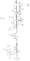
- FIG. 1 shows a schematic representation of some stations of a blister packaging machine 10, which are passed through in succession from a bottom sheet 11, in a conventional manner, a plurality of cup-like depressions 12 in a forming station, not shown, as indicated by the arrow H, which denotes the main transport direction of the bottom sheet 11.
- the bottom foil 11 first passes through a stationary filling station 13 in which a product 14, for example a tablet, is inserted from above into the cup-shaped depressions 12 of the bottom foil 11.
- the horizontally extending bottom foil 11 then reaches a deflection device 20, in which the bottom foil 11 is deflected in the form of an upwardly projecting wave-like loop and subsequently returned to the horizontal orientation.
- the deflection device 20 is vertically adjustable in height up and down, as indicated by the double arrow A, and forms a second drive device 15 for the bottom sheet 11th
- the bottom film is fed directly in front of a sealing station 18 to a cover film 16 which is deposited on the upper side of the bottom film 11 via a deflection roller 17.
- the sealing station 18 comprises vertically opening and closing sealing plates 18a and 18b, as indicated by the arrow C.
- the sealing plates 18a and 18b are heated and serve to beidesiegeln the cover sheet 16 on the bottom sheet 11 and thereby seal the cup-shaped depressions 12 of the bottom sheet 11.
- a first drive device 19 Downstream of the sealing station 18, ie in the main transport direction H behind the sealing station 18, a first drive device 19 is arranged for the blister strip 30 formed from the bottom foil 11, the inserted products 14 and the cover foil 16.
- the first drive device 19 comprises a gripper or pliers 19a, by means of which the blister band 30 can be gripped.
- the forceps 19a is along a linear guide 19b, which is parallel to the main transport direction H of the blister strip 30, between a sealing station 18 facing the starting position and one in Fig. 1 only shown in phantom end position and back to the starting position motorized, as indicated by the double arrow B in Fig. 1.
- the pliers 19a detects the blister band 30 in the initial position and is then moved to the end position, whereby the blister band 30 is preferred in the main direction of transport .H. In the end position, the pliers 19a releases the blister band 30 and returns to the starting position. In this way, an intermittent or cyclic preferential movement is applied to the blister strip 30 and thereby also to the bottom foil 11.
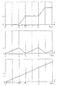
- the sealing device 18 While the first driving device 19 transports the blister band 30 and the bottom foil 11, the sealing device 18 is opened by moving the sealing plates 18a and 18b apart. As soon as the preferential movement of the blister strip 30 by means of the first drive device 19 has ended, the sealing plates 18a and 18b are closed, thereby sealing the cover film 16 to the bottom film 11 in the section located within the sealing station 18. At the same time the pliers 19a moves back to their starting position. During this time, the bottom foil 11 can not be transported by means of the first drive device 19. A path-time diagram representing the theoretical movement of the bottom foil 11 in the region of the filling station 13 solely as a result of the first drive device 19 is shown in FIG. 6a.
- the first drive device 19 releases the blister band 30 and returns to its initial position during a period T 1 during which the pliers 19 a again grasp the blister band 30.
- T 1 no movement of the blister band 30 or the bottom foil 11 takes place as a result of the first drive device 19.
- the sealing station 18 opens, the advancement of the blister band 30 and thus of the bottom foil 11 begins at a time t 1 by methods of the forceps of the first drive device 19 along the linear guide 19a 19b until the end position at a time t 2 is reached.
- the blister band 30 and the bottom foil 11 have covered a path s 2 . It closes again for a period T 3 , which corresponds to the period T 1 , a stoppage of the blister strip 30 and thus the bottom sheet 11 due to the first drive device 19 at.
- the second drive device 15 in the form of the deflection device 20 is provided between the filling station 13 and the sealing station 18, which causes an additional movement of the bottom foil 11 in the region of the filling station 13, wherein the drive movements of the first drive device 19 and the second drive device 15 so are superimposed that the bottom sheet 11 is transported at the filling station 13 at a constant speed.
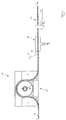
- the deflection device 20 comprises according to FIGS. 7 to 9 a horizontal, substantially perpendicular to the main transport direction H extending shaft 21, are rotatably mounted on the three pulleys 22 at mutual axial distance.
- the distance between the deflecting disks 22 relative to one another is variable, so that it is ensured that the cup-shaped depressions 12 of the bottom film 11 pass between the deflecting disks 22.
- the shaft 21 penetrates a rear wall 28 on a vertical slot 27 and is on the side facing away from the deflection plates 22 of the rear wall 28 via a gear 26 with a mounted on a support plate 31 servo motor 25 in connection.
- the deflection plates 22 are leaving only a narrow Slit on its upper side covered by a cover 24, which forms a guide element.
- the shaft 21 is connected to a guide block 29 which is slidably received in a guide groove 32 of the base plate 28.
- the shaft 21, the cover 24 and the guide block 29 can be vertically moved up and down on this seated deflection plates 22, wherein the guide is ensured by the engagement of the guide block 29 in the guide groove 32.
- each convexly curved guide plates 23 are arranged, which are attached to the base plate 28 and the vertical up and down movement of the shaft 21 and the deflection plates 22 do not participate.
- the bottom film 11 coming from the filling station passes through the deflection device 20 to form a loop projecting vertically upwards.
- the bottom foil 11 arrives at the deflection device 20 in a horizontal orientation from the filling station (on the left in FIG. 2), with the cup-shaped depressions 12, in each of which a product 14 is arranged, opening upwards.
- the bottom sheet 11 then dives under the associated baffle 23, which covers the cup-shaped depressions 12 and prevents the products 14 from falling out.
- the bottom sheet 11 undergoes a deflection by 90 ° vertically upwards and then passes through the gap between the deflection plates 22 and the cover 24, whereby it is deflected by forming the loop by 180 ° vertically downwards.
- the cover 24 prevents the products 14 from falling out of the cup-shaped depressions 12. Subsequently, the bottom foil 11 is again deflected by 90 ° and brought into their original horizontal orientation, wherein the further baffle 23 in this area falling out of Products 14 prevented. In this orientation, the bottom sheet 11 then passes to the sealing station 18th
- the movements of the first drive device 19 and the second drive device 15 or the deflection device are the same 20 so matched and synchronized that results in a continuous transport movement at a constant speed for the bottom sheet 11 in the filling station 13. This is determined in the period T 1 solely by the second drive device 15 and in the period T 2 by the superimpositions of the drive movements of the drive devices 19 and 15.
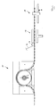
- a cycle of the sealing station 18 and the first drive device 19 including the drive by the second drive device 15 will be explained below with reference to FIGS. 2 to 5.
- the pliers 19 a are in their end position and the deflecting device 20 is in its lower starting position.
- the sealing station closes (arrow S), whereby the bottom foil 11 is clamped.
- the pincer 19a of the first drive device 19 returns to its initial position (arrow R) and the deflection device 20 moves vertically upward (arrow V 1 ), thereby exerting a transport movement at a constant speed on the bottom foil 11 in the region of the filling station becomes.
- the deflecting device 20 has reached its upper end position, while the pliers 19 a of the first drive device 19 has assumed its sealing position 18 facing the starting position and the blister band 30 has seized.
- the sealing station opens 18 (arrow O) and the first drive device 19 pulls the blister band 30 and thus also the bottom sheet 11 in the main transport direction H, as indicated by the arrow Z.
- the deflection device 20 moves downward (arrow V 2 ). Since the movements of the first drive device 19 and the deflection device 20 are carried out at different speeds, remains for the bottom foil 11 in the area the filling station a resulting transport movement at a constant speed, which corresponds to the speed during the period T 1 , ie alone due to the second drive device 15.
- Fig. 4 shows an intermediate position of the movements during the period T 2 , wherein the pliers 19a of the first drive device 19 are still in their forward movement (arrow Z) and the deflection device 20 in its downward movement (arrow V 2 ).
- FIG. 5 illustrates the end of the cycle at the time t 2 at the end of the period T 2 .
- the pliers 19a of the first drive device 19 has reached its end position and the deflection device 20 is in its lower starting position.
- a new cycle begins, so that the individual stations and components are in the same position as at time t 0 ( Figure 2) and the cycle is again repeated from the beginning.
Landscapes
- Engineering & Computer Science (AREA)
- Mechanical Engineering (AREA)
- Containers And Plastic Fillers For Packaging (AREA)
- Slide Fasteners (AREA)
- Package Closures (AREA)
- Auxiliary Devices For And Details Of Packaging Control (AREA)
Claims (8)
- Machine de conditionnement sous blister comprenant une station de remplissage (13), dans laquelle on peut disposer des produits (14) dans des évidements en forme de cuvette (12) d'une feuille de fond (11), et une station consécutive de scellement (18) dans laquelle une feuille de couverture (16) acheminée peut être scellée sur la feuille de fond (11) en formant une bande de blister (30), un premier dispositif d'entraînement (19) travaillant en cadence étant associé à la station de scellement (18) travaillant en cadence, au moyen duquel la feuille de fond (11) et la feuille de couverture (16) peuvent être transportées de manière discontinue à travers la station de scellement (18), caractérisée en ce qu'un deuxième dispositif d'entraînement (15) pour la feuille de fond (11) est disposé entre la station de remplissage (13) et la station de scellement (18), au moyen duquel la feuille de fond (11) peut être transportée de manière discontinue, les mouvements d'entraînement du premier dispositif d'entraînement (19) et du deuxième dispositif d'entraînement (15) étant superposés de telle façon que la feuille de fond (11) peut être transportée à vitesse constante à la station de remplissage (13) réalisée stationnaire.
- Machine de conditionnement sous blister selon la revendication 1, caractérisée en ce que le deuxième dispositif d'entraînement (15) comprend un dispositif de changement de direction (20) réglable entre une position de base et une position d'extension, permettant au moyen de réglage d'exercer une force de traction sur la feuille de fond (11) présente dans la station de remplissage (13).
- Machine de conditionnement sous blister selon la revendication 2, caractérisée en ce que le dispositif de changement de direction (20) peut être ramené de la position d'extension dans la position de base.
- Machine de conditionnement sous blister selon l'une quelconque des revendications 2 ou 3, caractérisée en ce que le dispositif de changement de direction (20) peut être réglé sensiblement vertical par rapport à la direction principale de transport (H) de la feuille de fond (11).
- Machine de conditionnement sous blister selon l'une quelconque des revendications 2 à 4, caractérisée en ce que le dispositif de changement de direction (20) présente un arbre (21) réglable motorisé, sur lequel sont disposés à distance les uns des autres plusieurs disques de changement de direction (22).
- Machine de conditionnement sous blister selon la revendication 5, caractérisée en ce que la distance séparant les disques de changement de direction (22) les uns des autres le long de l'arbre (21) est modifiable.
- Machine de conditionnement sous blister selon la revendication 5 ou 6, caractérisée en ce que les disques de changement de direction sont montés à rotation sur l'arbre (21).
- Machine de conditionnement sous blister selon l'une quelconque des revendications 2 à 7, caractérisée en ce que le dispositif de changement de direction (20) présente plusieurs éléments de guidage (23, 24), sur lesquels la feuille de fond (11) vient en contact par le côté ouvert des évidements (12) en forme de cuvette.
Applications Claiming Priority (3)
| Application Number | Priority Date | Filing Date | Title |
|---|---|---|---|
| DE10356055 | 2003-12-01 | ||
| DE10356055A DE10356055A1 (de) | 2003-12-01 | 2003-12-01 | Blister-Verpackungsmaschine |
| PCT/EP2004/012971 WO2005061330A1 (fr) | 2003-12-01 | 2004-11-16 | Machine de conditionnement sous blister |
Publications (2)
| Publication Number | Publication Date |
|---|---|
| EP1569849A1 EP1569849A1 (fr) | 2005-09-07 |
| EP1569849B1 true EP1569849B1 (fr) | 2006-06-07 |
Family
ID=34609410
Family Applications (1)
| Application Number | Title | Priority Date | Filing Date |
|---|---|---|---|
| EP04797922A Expired - Lifetime EP1569849B1 (fr) | 2003-12-01 | 2004-11-16 | Machine de conditionnement sous blister |
Country Status (9)
| Country | Link |
|---|---|
| US (1) | US20050268578A1 (fr) |
| EP (1) | EP1569849B1 (fr) |
| JP (1) | JP2007512189A (fr) |
| AT (1) | ATE328794T1 (fr) |
| BR (1) | BRPI0406456A (fr) |
| CA (1) | CA2513560A1 (fr) |
| DE (2) | DE10356055A1 (fr) |
| MX (1) | MXPA05008185A (fr) |
| WO (1) | WO2005061330A1 (fr) |
Families Citing this family (2)
| Publication number | Priority date | Publication date | Assignee | Title |
|---|---|---|---|---|
| ITBO20120379A1 (it) * | 2012-07-12 | 2014-01-13 | Marchesini Group Spa | Dispositivo di sigillatura di un nastro alveolato con una pellicola di rivestimento per ottenere una banda blister |
| CA3197766A1 (fr) | 2020-11-09 | 2022-05-12 | Marvin LEVAN | Ensemble de scellage et de coupe pour machine de thermoscellage |
Family Cites Families (22)
| Publication number | Priority date | Publication date | Assignee | Title |
|---|---|---|---|---|
| US3481100A (en) * | 1966-11-23 | 1969-12-02 | Anderson Bros Mfg Co | Method and apparatus for packaging in protective atmosphere |
| DE1806492A1 (de) * | 1968-10-31 | 1970-05-14 | Hassia Verpackung Ag | Vorrichtung zur Herstellung von aus einer thermoplastischen Folienbahn tiefgezogenen Verpackungsbehaelter |
| DE1942718A1 (de) * | 1969-08-22 | 1971-04-01 | Hassia Verpackung Ag | Verfahren und Vorrichtung zum Zuschneiden von Einzelpackungen aus einem zusammenhaengenden zwangsvorschubgefuehrten Folienband |
| DE2052551A1 (de) * | 1970-10-27 | 1972-06-22 | Fa. Ganzhorn u. Stirn, 7170 Schwäbisch Hall | Abfüllmaschine mit Formvorrichtung |
| US4018028A (en) * | 1971-07-23 | 1977-04-19 | Societe D'application Plastique Mecanique Et Electronique, Plastimecanique S.A. | Arrangement for aligning heat-sealable lids on mating product-filled containers |
| US3942934A (en) * | 1973-10-19 | 1976-03-09 | Takeda Chemical Industries, Ltd. | Mold assembly for use in packaging machine |
| US4233801A (en) * | 1978-07-31 | 1980-11-18 | Ashley-Butler, Inc. | Apparatus and process for the manufacture of disposable thermometers |
| FR2488213A1 (fr) * | 1980-08-06 | 1982-02-12 | Soyez Freres Sa | Dispositif pour fabriquer une nappe constituee de deux bandes enfermant entre elles une serie de tubes transversaux |
| IT1145011B (it) * | 1981-01-23 | 1986-11-05 | Ima Spa | Apparecchiatura per il controllo delle operazioni lungo la linea operativa di macchine confezionatrici, particolarmente di confezioni-"blisters" e simili |
| DE3325674A1 (de) * | 1983-07-15 | 1985-01-24 | Klinge Pharma GmbH, 8000 München | Vorschubueberwachung an einer maschine zum herstellen und verschliessen von blisterpackungen |
| IT1186935B (it) * | 1985-10-04 | 1987-12-16 | Newpack Srl | Apparato per l attivazione con ciclo continuo di macchine adibite alla formazione al riempiemento ed alla saldatura di contenitore ad esempio di macchine del tipo delle blisteratrici |
| US4819406A (en) * | 1987-09-25 | 1989-04-11 | Sanford Redmond Inc. | Compact form-fill-seal machine for automatic production of sealed packages |
| US5192484A (en) * | 1988-09-14 | 1993-03-09 | Matsuzawa Co., Ltd. | Method of forming blisters |
| US5366685A (en) * | 1989-07-18 | 1994-11-22 | Idemitsu Petrochemical Co., Ltd. | Process of molding thermoplastic sheet by plug assist vacuum forming |
| US5269123A (en) * | 1989-12-29 | 1993-12-14 | Massimo Marchesini | Device for sealing a film onto a blister band, particularly a polypropylene band |
| US5187921A (en) * | 1990-09-04 | 1993-02-23 | Glaxo Group Limited | Method and apparatus for filling cavities |
| US5369937A (en) * | 1993-05-10 | 1994-12-06 | Joule' Inc. | Continuous casting and packaging |
| DE59408359D1 (de) * | 1994-02-24 | 1999-07-08 | Gretag Imaging Ag | Schlaufenpuffer für Bandtransportvorrichtung |
| DE19501982B4 (de) * | 1995-01-24 | 2009-06-10 | Elau Gmbh | Zuführvorrichtung einer diskontinuierlich bahnförmiges Material verarbeitenden Maschine |
| DE19618769C1 (de) * | 1996-05-10 | 1997-06-26 | Horn & Noack Pharmatechn Gmbh | Vorrichtung zum Aufbringen einer Deckfolie auf eine eingeformte Behälter aufweisende Bodenfolie |
| US6024683A (en) * | 1998-03-09 | 2000-02-15 | Wilkes; Kenneth R. | Apparatus and method for fabricating containers |
| ITBO20010650A1 (it) * | 2001-10-26 | 2003-04-26 | Ima Spa | Metodo e macchina per la realizzazione di confezioni blister |
-
2003
- 2003-12-01 DE DE10356055A patent/DE10356055A1/de not_active Withdrawn
-
2004
- 2004-11-16 WO PCT/EP2004/012971 patent/WO2005061330A1/fr not_active Ceased
- 2004-11-16 CA CA002513560A patent/CA2513560A1/fr not_active Abandoned
- 2004-11-16 JP JP2006540290A patent/JP2007512189A/ja not_active Withdrawn
- 2004-11-16 DE DE502004000709T patent/DE502004000709D1/de not_active Expired - Fee Related
- 2004-11-16 BR BR0406456-9A patent/BRPI0406456A/pt not_active Application Discontinuation
- 2004-11-16 AT AT04797922T patent/ATE328794T1/de not_active IP Right Cessation
- 2004-11-16 MX MXPA05008185A patent/MXPA05008185A/es not_active Application Discontinuation
- 2004-11-16 US US10/533,783 patent/US20050268578A1/en not_active Abandoned
- 2004-11-16 EP EP04797922A patent/EP1569849B1/fr not_active Expired - Lifetime
Also Published As
| Publication number | Publication date |
|---|---|
| MXPA05008185A (es) | 2005-10-05 |
| CA2513560A1 (fr) | 2005-07-07 |
| JP2007512189A (ja) | 2007-05-17 |
| DE10356055A1 (de) | 2005-06-23 |
| EP1569849A1 (fr) | 2005-09-07 |
| WO2005061330A1 (fr) | 2005-07-07 |
| BRPI0406456A (pt) | 2005-12-06 |
| US20050268578A1 (en) | 2005-12-08 |
| DE502004000709D1 (de) | 2006-07-20 |
| ATE328794T1 (de) | 2006-06-15 |
Similar Documents
| Publication | Publication Date | Title |
|---|---|---|
| DE2327286C2 (de) | Verpackungsvorrichtung | |
| DE2721333C2 (de) | Vorrichtung zum Aufbringen von Überzugsstreifen auf eine Bahn von Behälterzuschnitten | |
| DE3031399A1 (de) | Verfahren und vorrichtung zum formen, fuellen und verschliessen von packungen | |
| DE69702667T2 (de) | Vorrichtung zum montieren von sägezahnschneidestreifen | |
| DE2735396A1 (de) | Form-, abfuell- und schweissmaschine fuer verpackungen | |
| DE2727340A1 (de) | Verfahren und vorrichtung zum automatischen verpacken von nahrungsmitteln | |
| DE1561966A1 (de) | Verfahren und Vorrichtung zum Verpacken von Waren | |
| DE2419682A1 (de) | Verpackungsvorrichtung und verpackungsverfahren | |
| DE2200419B2 (de) | Vorrichtung zur intermittierenden Zufuhr eines Abschnitts einer Folienbahn aus einer Vorratsrolle zum Verschließen eines Behälters | |
| DE2065712B2 (de) | Tiefziehmaschine zum herstellen von seitenwandverstaerkten behaeltern | |
| EP1569849B1 (fr) | Machine de conditionnement sous blister | |
| DE1586093B2 (de) | Vorrichtung zum aufbringen von aufreisstreifen auf ein einschlagmaterialband | |
| EP3048056B1 (fr) | Dispositif de scellage d'un emballage ou d'un materiau d'emballage | |
| CH433095A (de) | Verfahren zum automatischen Herstellen evakuierter Packungen und Vorrichtung zur Durchführung des Verfahrens | |
| DE102005018111A1 (de) | Verfahren zum Abrollen von Bahnmaterial in einer Verpackungsmaschine und Verpackungsmaschine | |
| DE2653196C3 (de) | Vorrichtung zum Zentrieren der Beschriftungen auf Verpackungen | |
| DE19737458C2 (de) | Vorrichtung und Verfahren zum gleichzeitigen Anbringen von Etiketten in zwei Reihen auf einer Verpackungsfolie | |
| EP3048057B1 (fr) | Dispositif d'usinage d'au moins une fermeture pour une machine d'emballage | |
| DE2358389A1 (de) | Verfahren und vorrichtung zum verpacken eines verpackungsguts | |
| EP1539583A1 (fr) | Procede et dispositif pour produire un conditionnement individuel primaire d'un cachet | |
| DE4135935A1 (de) | Verfahren und vorrichtung zum taktweisen thermoverformen von kunststoffolie im endlosband | |
| DE2301217A1 (de) | Verpackungsmaschine mit ununterbrochener bewegung | |
| DE102008020736B4 (de) | Verfahren zum reihenweisen Aufbringen von Etiketten auf ein Band sowie Etikettierer zur Durchführung dieses Verfahrens | |
| DE3609480C1 (de) | Vorrichtung zum Beschicken einer kontinuierlich arbeitenden Behaelterverschliessmaschine mit Deckeln | |
| DE2727085A1 (de) | Vorrichtung zum verschliessen des kopfendes von behaeltern |
Legal Events
| Date | Code | Title | Description |
|---|---|---|---|
| PUAI | Public reference made under article 153(3) epc to a published international application that has entered the european phase |
Free format text: ORIGINAL CODE: 0009012 |
|
| 17P | Request for examination filed |
Effective date: 20050504 |
|
| AK | Designated contracting states |
Kind code of ref document: A1 Designated state(s): AT BE BG CH CY CZ DE DK EE ES FI FR GB GR HU IE IS IT LI LU MC NL PL PT RO SE SI SK TR |
|
| AX | Request for extension of the european patent |
Extension state: AL HR LT LV MK YU |
|
| GRAP | Despatch of communication of intention to grant a patent |
Free format text: ORIGINAL CODE: EPIDOSNIGR1 |
|
| GRAS | Grant fee paid |
Free format text: ORIGINAL CODE: EPIDOSNIGR3 |
|
| GRAA | (expected) grant |
Free format text: ORIGINAL CODE: 0009210 |
|
| AK | Designated contracting states |
Kind code of ref document: B1 Designated state(s): AT BE BG CH CY CZ DE DK EE ES FI FR GB GR HU IE IS IT LI LU MC NL PL PT RO SE SI SK TR |
|
| PG25 | Lapsed in a contracting state [announced via postgrant information from national office to epo] |
Ref country code: IT Free format text: LAPSE BECAUSE OF FAILURE TO SUBMIT A TRANSLATION OF THE DESCRIPTION OR TO PAY THE FEE WITHIN THE PRESCRIBED TIME-LIMIT;WARNING: LAPSES OF ITALIAN PATENTS WITH EFFECTIVE DATE BEFORE 2007 MAY HAVE OCCURRED AT ANY TIME BEFORE 2007. THE CORRECT EFFECTIVE DATE MAY BE DIFFERENT FROM THE ONE RECORDED. Effective date: 20060607 Ref country code: SK Free format text: LAPSE BECAUSE OF FAILURE TO SUBMIT A TRANSLATION OF THE DESCRIPTION OR TO PAY THE FEE WITHIN THE PRESCRIBED TIME-LIMIT Effective date: 20060607 Ref country code: SI Free format text: LAPSE BECAUSE OF FAILURE TO SUBMIT A TRANSLATION OF THE DESCRIPTION OR TO PAY THE FEE WITHIN THE PRESCRIBED TIME-LIMIT Effective date: 20060607 Ref country code: RO Free format text: LAPSE BECAUSE OF FAILURE TO SUBMIT A TRANSLATION OF THE DESCRIPTION OR TO PAY THE FEE WITHIN THE PRESCRIBED TIME-LIMIT Effective date: 20060607 Ref country code: PL Free format text: LAPSE BECAUSE OF FAILURE TO SUBMIT A TRANSLATION OF THE DESCRIPTION OR TO PAY THE FEE WITHIN THE PRESCRIBED TIME-LIMIT Effective date: 20060607 Ref country code: CZ Free format text: LAPSE BECAUSE OF FAILURE TO SUBMIT A TRANSLATION OF THE DESCRIPTION OR TO PAY THE FEE WITHIN THE PRESCRIBED TIME-LIMIT Effective date: 20060607 Ref country code: NL Free format text: LAPSE BECAUSE OF FAILURE TO SUBMIT A TRANSLATION OF THE DESCRIPTION OR TO PAY THE FEE WITHIN THE PRESCRIBED TIME-LIMIT Effective date: 20060607 Ref country code: IE Free format text: LAPSE BECAUSE OF FAILURE TO SUBMIT A TRANSLATION OF THE DESCRIPTION OR TO PAY THE FEE WITHIN THE PRESCRIBED TIME-LIMIT Effective date: 20060607 Ref country code: GB Free format text: LAPSE BECAUSE OF FAILURE TO SUBMIT A TRANSLATION OF THE DESCRIPTION OR TO PAY THE FEE WITHIN THE PRESCRIBED TIME-LIMIT Effective date: 20060607 Ref country code: FI Free format text: LAPSE BECAUSE OF FAILURE TO SUBMIT A TRANSLATION OF THE DESCRIPTION OR TO PAY THE FEE WITHIN THE PRESCRIBED TIME-LIMIT Effective date: 20060607 |
|
| REG | Reference to a national code |
Ref country code: GB Ref legal event code: FG4D Free format text: NOT ENGLISH |
|
| REG | Reference to a national code |
Ref country code: CH Ref legal event code: EP |
|
| REG | Reference to a national code |
Ref country code: IE Ref legal event code: FG4D Free format text: LANGUAGE OF EP DOCUMENT: GERMAN |
|
| REF | Corresponds to: |
Ref document number: 502004000709 Country of ref document: DE Date of ref document: 20060720 Kind code of ref document: P |
|
| PG25 | Lapsed in a contracting state [announced via postgrant information from national office to epo] |
Ref country code: SE Free format text: LAPSE BECAUSE OF FAILURE TO SUBMIT A TRANSLATION OF THE DESCRIPTION OR TO PAY THE FEE WITHIN THE PRESCRIBED TIME-LIMIT Effective date: 20060907 Ref country code: DK Free format text: LAPSE BECAUSE OF FAILURE TO SUBMIT A TRANSLATION OF THE DESCRIPTION OR TO PAY THE FEE WITHIN THE PRESCRIBED TIME-LIMIT Effective date: 20060907 |
|
| PG25 | Lapsed in a contracting state [announced via postgrant information from national office to epo] |
Ref country code: ES Free format text: LAPSE BECAUSE OF FAILURE TO SUBMIT A TRANSLATION OF THE DESCRIPTION OR TO PAY THE FEE WITHIN THE PRESCRIBED TIME-LIMIT Effective date: 20060918 |
|
| PG25 | Lapsed in a contracting state [announced via postgrant information from national office to epo] |
Ref country code: PT Free format text: LAPSE BECAUSE OF FAILURE TO SUBMIT A TRANSLATION OF THE DESCRIPTION OR TO PAY THE FEE WITHIN THE PRESCRIBED TIME-LIMIT Effective date: 20061107 |
|
| PG25 | Lapsed in a contracting state [announced via postgrant information from national office to epo] |
Ref country code: BE Free format text: LAPSE BECAUSE OF NON-PAYMENT OF DUE FEES Effective date: 20061130 Ref country code: MC Free format text: LAPSE BECAUSE OF NON-PAYMENT OF DUE FEES Effective date: 20061130 |
|
| NLV1 | Nl: lapsed or annulled due to failure to fulfill the requirements of art. 29p and 29m of the patents act | ||
| GBV | Gb: ep patent (uk) treated as always having been void in accordance with gb section 77(7)/1977 [no translation filed] |
Effective date: 20060607 |
|
| REG | Reference to a national code |
Ref country code: IE Ref legal event code: FD4D |
|
| DAX | Request for extension of the european patent (deleted) | ||
| PLBE | No opposition filed within time limit |
Free format text: ORIGINAL CODE: 0009261 |
|
| STAA | Information on the status of an ep patent application or granted ep patent |
Free format text: STATUS: NO OPPOSITION FILED WITHIN TIME LIMIT |
|
| EN | Fr: translation not filed | ||
| 26N | No opposition filed |
Effective date: 20070308 |
|
| BERE | Be: lapsed |
Owner name: IWK VERPACKUNGSTECHNIK G.M.B.H. Effective date: 20061130 |
|
| PGFP | Annual fee paid to national office [announced via postgrant information from national office to epo] |
Ref country code: DE Payment date: 20071124 Year of fee payment: 4 |
|
| PG25 | Lapsed in a contracting state [announced via postgrant information from national office to epo] |
Ref country code: AT Free format text: LAPSE BECAUSE OF NON-PAYMENT OF DUE FEES Effective date: 20061116 |
|
| PG25 | Lapsed in a contracting state [announced via postgrant information from national office to epo] |
Ref country code: FR Free format text: LAPSE BECAUSE OF FAILURE TO SUBMIT A TRANSLATION OF THE DESCRIPTION OR TO PAY THE FEE WITHIN THE PRESCRIBED TIME-LIMIT Effective date: 20070309 Ref country code: GR Free format text: LAPSE BECAUSE OF FAILURE TO SUBMIT A TRANSLATION OF THE DESCRIPTION OR TO PAY THE FEE WITHIN THE PRESCRIBED TIME-LIMIT Effective date: 20060908 |
|
| PG25 | Lapsed in a contracting state [announced via postgrant information from national office to epo] |
Ref country code: EE Free format text: LAPSE BECAUSE OF FAILURE TO SUBMIT A TRANSLATION OF THE DESCRIPTION OR TO PAY THE FEE WITHIN THE PRESCRIBED TIME-LIMIT Effective date: 20060607 Ref country code: BG Free format text: LAPSE BECAUSE OF FAILURE TO SUBMIT A TRANSLATION OF THE DESCRIPTION OR TO PAY THE FEE WITHIN THE PRESCRIBED TIME-LIMIT Effective date: 20060907 |
|
| PG25 | Lapsed in a contracting state [announced via postgrant information from national office to epo] |
Ref country code: HU Free format text: LAPSE BECAUSE OF FAILURE TO SUBMIT A TRANSLATION OF THE DESCRIPTION OR TO PAY THE FEE WITHIN THE PRESCRIBED TIME-LIMIT Effective date: 20061208 Ref country code: LU Free format text: LAPSE BECAUSE OF NON-PAYMENT OF DUE FEES Effective date: 20061116 Ref country code: IS Free format text: LAPSE BECAUSE OF FAILURE TO SUBMIT A TRANSLATION OF THE DESCRIPTION OR TO PAY THE FEE WITHIN THE PRESCRIBED TIME-LIMIT Effective date: 20060607 Ref country code: TR Free format text: LAPSE BECAUSE OF FAILURE TO SUBMIT A TRANSLATION OF THE DESCRIPTION OR TO PAY THE FEE WITHIN THE PRESCRIBED TIME-LIMIT Effective date: 20060607 |
|
| PG25 | Lapsed in a contracting state [announced via postgrant information from national office to epo] |
Ref country code: FR Free format text: LAPSE BECAUSE OF FAILURE TO SUBMIT A TRANSLATION OF THE DESCRIPTION OR TO PAY THE FEE WITHIN THE PRESCRIBED TIME-LIMIT Effective date: 20060607 Ref country code: CY Free format text: LAPSE BECAUSE OF FAILURE TO SUBMIT A TRANSLATION OF THE DESCRIPTION OR TO PAY THE FEE WITHIN THE PRESCRIBED TIME-LIMIT Effective date: 20060607 |
|
| REG | Reference to a national code |
Ref country code: CH Ref legal event code: PL |
|
| PG25 | Lapsed in a contracting state [announced via postgrant information from national office to epo] |
Ref country code: IT Free format text: LAPSE BECAUSE OF NON-PAYMENT OF DUE FEES Effective date: 20081116 |
|
| PG25 | Lapsed in a contracting state [announced via postgrant information from national office to epo] |
Ref country code: LI Free format text: LAPSE BECAUSE OF NON-PAYMENT OF DUE FEES Effective date: 20081130 Ref country code: CH Free format text: LAPSE BECAUSE OF NON-PAYMENT OF DUE FEES Effective date: 20081130 Ref country code: DE Free format text: LAPSE BECAUSE OF NON-PAYMENT OF DUE FEES Effective date: 20090603 |
|
| PGFP | Annual fee paid to national office [announced via postgrant information from national office to epo] |
Ref country code: IT Payment date: 20071130 Year of fee payment: 4 |