EP1569846B1 - Tür zur anordnung zwischen einem cockpit und einer kabine eines flugzeuges - Google Patents
Tür zur anordnung zwischen einem cockpit und einer kabine eines flugzeuges Download PDFInfo
- Publication number
- EP1569846B1 EP1569846B1 EP03799709A EP03799709A EP1569846B1 EP 1569846 B1 EP1569846 B1 EP 1569846B1 EP 03799709 A EP03799709 A EP 03799709A EP 03799709 A EP03799709 A EP 03799709A EP 1569846 B1 EP1569846 B1 EP 1569846B1
- Authority
- EP
- European Patent Office
- Prior art keywords
- door
- trapdoor
- cockpit
- cabin
- flap
- Prior art date
- Legal status (The legal status is an assumption and is not a legal conclusion. Google has not performed a legal analysis and makes no representation as to the accuracy of the status listed.)
- Expired - Lifetime
Links
Images


Classifications
-
- E—FIXED CONSTRUCTIONS
- E05—LOCKS; KEYS; WINDOW OR DOOR FITTINGS; SAFES
- E05B—LOCKS; ACCESSORIES THEREFOR; HANDCUFFS
- E05B65/00—Locks or fastenings for special use
- E05B65/10—Locks or fastenings for special use for panic or emergency doors
- E05B65/102—Locks or fastenings for special use for panic or emergency doors opening under pressure on the surface of the door itself
-
- B—PERFORMING OPERATIONS; TRANSPORTING
- B64—AIRCRAFT; AVIATION; COSMONAUTICS
- B64C—AEROPLANES; HELICOPTERS
- B64C1/00—Fuselages; Constructional features common to fuselages, wings, stabilising surfaces or the like
- B64C1/14—Windows; Doors; Hatch covers or access panels; Surrounding frame structures; Canopies; Windscreens accessories therefor, e.g. pressure sensors, water deflectors, hinges, seals, handles, latches, windscreen wipers
- B64C1/1407—Doors; surrounding frames
- B64C1/1423—Passenger doors
-
- B—PERFORMING OPERATIONS; TRANSPORTING
- B64—AIRCRAFT; AVIATION; COSMONAUTICS
- B64C—AEROPLANES; HELICOPTERS
- B64C1/00—Fuselages; Constructional features common to fuselages, wings, stabilising surfaces or the like
- B64C1/14—Windows; Doors; Hatch covers or access panels; Surrounding frame structures; Canopies; Windscreens accessories therefor, e.g. pressure sensors, water deflectors, hinges, seals, handles, latches, windscreen wipers
- B64C1/1407—Doors; surrounding frames
- B64C1/1469—Doors between cockpit and cabin
-
- B—PERFORMING OPERATIONS; TRANSPORTING
- B64—AIRCRAFT; AVIATION; COSMONAUTICS
- B64D—EQUIPMENT FOR FITTING IN OR TO AIRCRAFT; FLIGHT SUITS; PARACHUTES; ARRANGEMENT OR MOUNTING OF POWER PLANTS OR PROPULSION TRANSMISSIONS IN AIRCRAFT
- B64D45/00—Aircraft indicators or protectors not otherwise provided for
- B64D45/0015—Devices specially adapted for the protection against criminal attack, e.g. anti-hijacking systems
- B64D45/0021—Devices specially adapted for the protection against criminal attack, e.g. anti-hijacking systems means for restricting access to flight deck
- B64D45/0028—Devices specially adapted for the protection against criminal attack, e.g. anti-hijacking systems means for restricting access to flight deck doors or door arrangements specially adapted to restrict unauthorized access
-
- B—PERFORMING OPERATIONS; TRANSPORTING
- B64—AIRCRAFT; AVIATION; COSMONAUTICS
- B64C—AEROPLANES; HELICOPTERS
- B64C1/00—Fuselages; Constructional features common to fuselages, wings, stabilising surfaces or the like
- B64C2001/009—Fuselages; Constructional features common to fuselages, wings, stabilising surfaces or the like comprising decompression panels or valves for pressure equalisation in fuselages or floors
Definitions
- the present invention relates to a door intended to be interposed between a cockpit and a cabin of an aircraft, as well as to a door system composed of such a door and an associated door frame.
- this door In this technical field, there is a conventional door separating the cockpit and the cabin of an aircraft, this door usually having a relatively simple design and having a cockpit side and a cabin side, respectively oriented towards the cockpit and towards the cabin of the aircraft, when the door is in a closed position.
- the door is mounted on a door frame so that it can open indifferently to the cockpit side and to the cabin side. In this way, when a depressurization occurs in the cockpit or in the cabin of the aircraft, the door can be opened respectively to the cockpit side and to the cabin side to create a ventilation between these two compartments. In addition, note that this dual possibility of opening up the door generally generates the presence of a gap between the door and its associated door frame.
- a simple way of eliminating the gap initially provided between the door and its associated door frame is to design the latter so that it partially overlaps one of the two sides of the door.
- the cabin side is preferably chosen, in particular so that the hinges located between this door and the door frame are not accessible from the cabin of the aircraft, again for security reasons.
- the door frame only allows the opening of the door on the cockpit side only. Therefore, when a depressurization occurs in the cabin of the aircraft, the door can not open towards the cabin side, and therefore prohibits the passage of an air flow between the cockpit and the cabin, through the door frame.
- ventilation areas can be provided between the cockpit and the cabin to ensure a permanent ventilation between these two compartments of the aircraft, the number limited space available in the cockpit to accommodate these ventilation surfaces is not sufficient to ensure a satisfactory ventilation, meeting the regulatory requirements related to cases of depressurization of the cabin of the aircraft.
- the invention therefore aims to provide a door intended to be interposed between a cockpit and a cabin of an aircraft, the door at least partially overcoming the disadvantages mentioned above relating to the embodiments of the prior art.
- the object of the invention is to provide a door whose design is compatible with the measures mentioned above to enhance the safety of flight crew located in the cockpit, while being able to cope with a depressurization occurring at the same time. inside the aircraft, and more specifically to a depressurization occurring in the cabin of this aircraft.
- the purpose of the invention is also to propose a door system intended to be interposed between a cockpit and a cabin of an aircraft, the system comprising a door frame and a door such as that meeting the stated purposes. above.
- the design of the door according to the invention is adapted to deal with a depressurization occurring inside the aircraft, and more specifically to a depressurization occurring in the cabin of this aircraft, even when this door is mounted. on an associated door frame so that it can only open towards the cockpit side.
- the flap provided on the door can be unlocked automatically when the difference in air pressure applying to each side of the door is greater than a predetermined value, this predetermined value can advantageously correspond to a value translating significant depressurization in the cabin of the aircraft.
- the shutter opens towards the cabin side of the door, in order to free the passage crossing this door, and consequently to generate the creation of a flow of air between the cockpit and the cabin of the aircraft.
- the door according to the invention is able to provide ventilation that fully meets the regulatory requirements related to depressurization cases in the cabin of the aircraft, while being compatible with the measures mentioned above aimed at enhancing safety.
- flight crew located in the cockpit including that relating to the removal of the gap between the door and its associated door frame, which may cause an impossibility of opening this door to the cabin side.
- the shutter capable of closing the passage through the door is automatically unlocked.
- this predetermined value is such that it is able to generate on the shutter sufficient force to cause an automatic opening of the unlocked shutter towards the cabin side.
- the unlocked shutter can be opened automatically under the effect of a force resulting directly from the pressure difference prevailing on both sides of the shutter.
- the locking / unlocking mechanism of the flap is mounted on the shutter of the door.
- the shutter and its locking / unlocking mechanism can be made jointly, independently of the rest of the door, constituted by a main body of the door provided with the through passage.
- the locking / unlocking mechanism intended to be coupled to the door flap is of the pneumatic mechanism type, integrating no component requiring power supply.
- pneumatic mechanism is designed to generate an automatic release of the shutter under the effect of a simple force generated by the difference in air pressure exerted on each side of the door.
- the latter can actually be set in motion and transmit this movement to one or more latches holding the flap in a locked position shutter of passage, so that these locks release the shutter frame and then allow an opening of the shutter.
- the secondary flap comprises an upper end and a lower end, the lower end being hingedly connected to the flap, and the upper end being hingedly connected to the motion transmission means.
- the secondary flap is then able to pivot around its lower end.
- the movement transmission means may also comprise a guide bushing integral with the door flap, and inside which the transmission rod is adapted to slide.
- each lock of the locking / unlocking mechanism is secured to a lever that can be actuated in order to unlock the shutter manually, a bolt return spring being arranged between the lever and the guide bushing of the movement transmission means. .
- the motion transmission means may comprise anti-acceleration means intended to stop the movement of the transmission rod when it is driven by a movement of a speed greater than a predetermined speed, and therefore intended to stop the movement of all elements of the locking / unlocking mechanism.
- anti-acceleration means intended to stop the movement of the transmission rod when it is driven by a movement of a speed greater than a predetermined speed, and therefore intended to stop the movement of all elements of the locking / unlocking mechanism.
- these anti-acceleration means causing the blocking of the transmission rod are easily surpassable when manually operating the lever / levers from inside the cockpit.
- the anti-acceleration means remain inoperative when the transmission rod is driven by a relatively slow movement, of a speed less than the predetermined speed, such as that encountered during a depressurization of the cabin of the aircraft, or during severe turbulence in flight.
- an alternative solution to that described above and also to reduce the risk of unlocking the flap following the impact of bales or a mass against the door is to provide that for each lock of the locking mechanism / unlocking, the motion transmission means also comprise stop means provided with an inertial mass able to move automatically from a withdrawal position to a stop position, following a shock occurring on the upper intensity door or equal to a predetermined intensity, to constitute a stop for a stop member secured to the lock.
- the blocking of the stop member simultaneously causes locking of the lock, so that the flap can not be unlocked.
- the abutment means remain inoperative when the inertial mass is subjected to an acceleration lower than the acceleration caused by a shock of intensity equal to the predetermined intensity, such acceleration being able to be encountered in particular when severe turbulence in flight.
- the unlocking locking mechanism may include a system for balancing the secondary flap, the balancing system being designed to prohibit, following an impact on the door and more specifically on the shutter of this door, any movement of the secondary flap may cause the unlocking of this flap.
- the balancing device is designed so as to balance the engine moment printed by the secondary flap, under the acceleration received by the shock produced on the door.
- the locking / unlocking mechanism is protected by a protective cover, mounted on the cockpit side of the door flap and not opposing the pressure balance, this cover can for example take the form of a grid.
- this cover can for example take the form of a grid.
- the portion of the flap provided with at least one through hole is covered with a filter arranged on the cabin side of the door and masking the location of each orifice, the filter being held against the flap by an anti - ballistics assembled on the shutter.
- the filter provided advantageously prevents these holes are clogged with dust, clogging of one or more of these holes may have the consequence of causing a malfunction of the lock / unlock mechanism of the flap.
- the anti-ballistic protection grid is assembled on the shutter with the aid of a plurality of studs passing through the shutter, and only removable from the cockpit side of the door.
- the flap comprises a lower portion provided with pivoting hooks intended firstly to hold the flap in a closed position of the passage when it is locked, and secondly to allow pivoting of the flap towards the door. cabin side when unlocked.
- the flap may comprise an upper portion provided with shutter retention means in the passage, these retaining means being preferably constituted by at least one ball pusher adapted to cooperate with the flap frame provided in the door.
- these retaining means make it possible to prevent the flap from tilting when the locking / unlocking mechanism has been inadvertently actuated, and not following a difference in air pressure that has generated automatic unlocking of the flap. .
- this effort threshold is naturally determined so that it is strictly less than any force exerted on the shutter and its associated locking / unlocking mechanism, resulting from a pressure difference that led to the automatic unlocking of the shutter .
- these retaining means are installed between the flap frame and the flap, as soon as the flap is unlocked, the latter is automatically opened towards the cabin side of the aircraft.
- the door preferably comprises a main door body and a flap adapted to be mounted on the main door body in order to seal the passage, the shutter equipped with the locking / unlocking mechanism being completely removable of the main door body.
- the assembly and disassembly of the shutter with its mechanism of locking / unlocking can be done quickly and without tools.
- the main door body and the flap can be made of an anti-ballistic material.
- the present invention also relates to a door system intended to be interposed between a cockpit and a cabin of an aircraft, the system comprising a door frame and a door having a cockpit side and a cabin side , the door frame being adapted to partially cover the cabin side of the door and allowing only an opening of the door to the cockpit side.
- the door is a door such as that also object of the invention and described above.
- FIG. 1 With reference to FIG. 1, one can see a front part 1 of an aircraft, provided with a door system 2 interposed between a cockpit 4 and a cabin 6, the door system 2 comprising a door 8 according to a method of preferred embodiment of the present invention.
- the door system 2 is arranged at a partition 10 separating the cockpit 4 and the cabin 6, these two compartments being in particular and respectively intended to accommodate the flight crew and passengers of the aircraft.
- the door 8 of substantially parallelepipedal shape and located perpendicular to a floor surface 9 of the aircraft, has a cockpit side 8a and a cabin side 8b, respectively oriented towards the cockpit 4 and to the cabin 6 of the aircraft. when the door 8 occupies a closed position such as that shown in FIG. 1.
- the door system 2 comprises the door 8 and a door frame 12, the latter defining a passage 14 adapted to communicate the cockpit 4 and the cabin 6 of the aircraft.
- the door 8 is mounted on the door frame 12 by hinges 16 aligned along an axis (not shown) perpendicular to the floor surface 9.
- the hinges 16 are located on the cockpit side 8a of the door 8, so as not to be accessible from the cabin 6.
- the door frame 12 has an abutment surface 12a partially covering the cabin side 8b of the door 8 when the latter is in a closed position, that is to say when it closes the passage 14 and rests in a housing 15 provided in the door frame 12, the housing 15 being of substantially complementary shape to that of the door 8.
- the surface stop 12a has a frame shape covering a peripheral portion of the cabin side 8b of the door 8. In this way, the assembly made does not create a gap between the door 8 and its associated door frame 12, so that terrorists located in the cabin 6 of the aircraft can not shoot bullets between these two elements.
- the door 8 only allows an opening of the door 8 to the cockpit side 8a.
- the door 8 according to the invention could be mounted on its associated door frame 12 in any other way, without departing from the scope of the invention.
- the door 8 comprises a main door body 18 provided with at least one through passage 20 capable of communicating the cockpit 4 and the cabin 6.
- the door 8 comprises a flap 22 adapted to close the passage 20, always so that there is no gap between the flap 22 and a flap frame 24, the latter being provided in the main door body 18 and defining the passage 20.
- the cockpit side 8a of the door 8 described above consists of a cockpit side 18a of the main door body 18 as well as a cockpit side 22a of the flap 22, the cockpit sides 18a and 22a are of course oriented towards the cockpit 4 of the aircraft.
- the cabin side 8b of the door 8 described above consists of a cabin side 18b of the main door body 18 as well as a cabin side 22b of the flap 22, the cabin sides 18b and 22b being oriented towards the cabin 6 of the aircraft.
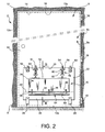
- the flap frame 24 has an abutment surface 24a partially covering the cockpit side 22a of the flap 22, when the flap 22 is in a closed position of the passage 20, such as that shown in FIGS. 2 and 3. it can be seen in Figure 3, the abutment surface 24a has a frame shape covering a peripheral portion of the cockpit side 22a of the flap 22. In this way, the assembly made does not create a gap between the flap 22 and its associated flap frame 24, so that terrorists located in the cabin 6 of the aircraft can not fire bullets between these two elements.
- the main door body 18 and the flap 22 are made of an anti-ballistic material such as fiberglass and Kevlar ® .
- the door frame 12 of the door system 2 can also be made in this same type of material.
- the flap 22, preferably of substantially parallelepipedal shape, is able to be held locked in the passage 20, in particular by means of pivoting hooks 26 integral with a lower portion 28 of the flap 22.
- the pivoting hooks 26 are preferably aligned along an axis (not shown) parallel to the floor surface 9, and are preferably simply placed in bearing against the cockpit side 18a of the main door body 18.
- the hooks 26 allow the opening and pivoting of the flap 22 towards the cabin side 8b of the door 8, that is, to say to the cabin 6 of the aircraft.
- the pivot hooks 26 preferably being placed in abutment against the cockpit side 18a of the main door body 18, the flap 22 can be mounted and disassembled quickly without tools.
- the door 8 further comprises a locking / unlocking mechanism 30 of the flap 22, this mechanism 30 being arranged on the cockpit 8a of the door 8 so as not to be accessible from the cabin 6 of the aircraft.
- the mechanism 30, capable of automatically unlocking the flap 22, is preferably integrally mounted on the cockpit side 22a of the flap 22, and protected by a protective cover 32 (only shown in FIGS. 3 and 4) also assembled on the cockpit side 22a of the flap 22.
- the cover 32 does not oppose the pressure balance, and takes for example the form of a grid.
- the locking / unlocking mechanism 30 is of the pneumatic operating type, and is capable of automatically unlocking the flap 22 when the difference between a cockpit pressure corresponding to the air pressure applying against the cockpit side 8a of the door 8 and a cabin pressure corresponding to the air pressure applying against the cabin side 8b of the same door 8, is greater than a value predetermined.
- a value predetermined e.g., a value predetermined for example less than 40 mbar
- the locking / unlocking mechanism 30 comprises a secondary flap 34, preferably of substantially parallelepipedal shape and having first and second surfaces 34a and 34b opposite one another. to the other.
- the secondary flap 34 is assembled in an articulated manner on the flap 22, by means of hinges 36 integral with a lower end 38 of the secondary flap 34, and arranged along an axis 40 substantially parallel to the floor surface 9 and to the axis of the pivot hooks 26 of the flap 22.
- the mechanism 30 comprises a membrane 42 defining a chamber, this membrane 42 preferably being of the small forge bellows type.
- the membrane 42 has a first end 42a secured to the second surface 34b of the secondary flap 34, and a second end 42b secured to a portion 44 of the flap 22, provided with a plurality of through orifices. 46.
- a portion 48 of the second surface 34b in contact with the chamber defined by the membrane 42, is subjected to the cabin pressure because of the presence of the orifices 46 on the portion 44 of the flap 22.
- a portion 50 of the first surface 34a located opposite the portion 48 of the second surface 34b, is in turn subjected to cockpit pressure.
- the locking / unlocking mechanism 30 furthermore has motion transmission means, connected on the one hand in an articulated manner to an upper end 52 of the secondary flap. 34, and secondly in solidarity with at least one latch 54.
- the mechanism 30 comprises two latches 54, each of them being intended to cooperate with the cockpit side 18a of the main door body 18, and more specifically with an upper portion of the flap frame 24 facing the cockpit 4 of the aircraft.
- the motion transmission means comprise a connecting rod 56 of which a first end 56a is hingedly connected to the upper end 52 of the secondary flap 34.
- the motion transmission means comprise a sliding transmission rod 58 provided with a first end 58a, hingedly connected to a second end 56b of the connecting rod 56.
- the transmission rod 58 is therefore capable of describing a sliding movement through a guide sleeve 60, integrally mounted on the cockpit side 22a of the flap 22.
- the latch 54 being integrally connected to a second end 58b of the transmission rod 58, it is therefore capable of being driven by the same sliding movement as that described by the rod 58, this movement preferably being effected along an axis substantially perpendicular to the floor surface 9 and the axis 40 of pivoting of the secondary flap 34.
- the guide sleeve 60 is preferably of the ball guide bushing type, capable of providing a good guide of the transmission rod 58 and the latch 54, therefore not requiring the addition of a guide slide lock in which the risk of seizure thereof are often very important.
- the locking / unlocking mechanism 30 is then designed so that when the cockpit pressure exceeds the cabin pressure by the predetermined value, preferably corresponding to a value representing a significant depressurization in the cabin 6 of the aircraft, the pivoting of the secondary flap 34 about the axis 40 is large enough to cause a withdrawal of the latches 54 of the flap frame 24, following the sliding of the transmission rod 58 towards the floor surface 9 of the aircraft.
- the flap 22 of the door 8 is then unlocked.
- the predetermined value of air pressure difference is sufficient to generate, on a set consisting of the flap 22 and the locking / unlocking mechanism 30, a force leading to the automatic opening of the flap 22 unlocked to the side cabin 8b door 8.
- this force must also be sufficient to cause an opening of the flap 22, even when the latter is coupled to retaining means 62.
- part of the shutter 22, such as an upper end 63 can be provided with retaining means 62 (only shown in Figure 2), so that actuation of the mechanism 30 inadvertently does not cause the opening of the flap 22.
- the retaining means 62 may be of the type of ball pushers intended to cooperate with the flap frame 24 of the main door body 18.
- the pressure difference that led to the unlocking of the flap 22 results in a total release of the passage 20 in less than 200 ms, after which an air flow can easily pass through this passage 20 to provide ventilation between the cockpit 4 and the cabin 6 of the aircraft.
- Figure 4 shows the door 8 when in a closed position, and at the beginning of the opening of the flap 22 to the cab side 8b of the door 8.
- the manual actuating levers 64 comprise a portion extending externally to the protective cover 32, so as to be easily accessible to people inside the cockpit. 4 of the aircraft.
- a return spring 66 of each latch 54 is arranged between the lever 64 and the guide sleeve 60.
- the portion 44 of the flap 22 provided with orifices 46 is covered by a filter 68.
- filter 68 is disposed on the cabin side 22b of the flap 22, and has for main function to hide the location of these orifices 46, so that they are not visible by terrorists located in the cabin 6 of the aircraft.
- the filter 68 is held against the cabin side 22b with the aid of an anti-ballistic protection grid 70 able to pass air, assembled on the flap 22 by means of a plurality of studs 72, crossing the same flap 22 and being only removable from the cockpit side. 22a of flap 22.
- the movement transmission means comprise anti-movement means. acceleration 74.
- the anti-acceleration means 74 are arranged substantially parallel to the transmission rod 58, and are integral on the one hand with the lever 64, and on the other hand with a support 76 mounted integrally on the cockpit side 22a of the shutter 22. It is noted that without departing from the scope of the invention, instead of being integral with the lever 64, the anti-acceleration means 74 could be directly integral with the transmission rod 58.
- the support 76 is provided with a through-hole 78 through which the transmission rod 58 passes, so that the latter is able to describe its sliding movement with respect to the shutter 22.
- the anti-acceleration means 74 comprising for example an axis 80 able to slide and to be locked in a body locking members 82 are then designed such that the axis 80 is stopped in its associated blocking body 82 when the speed of the axis 80 relative to the body 82 exceeds a predetermined speed value.
- the speed of the axis 80 with respect to its associated locking body 82 being identical to the speed of the transmission rod 58 with respect to the flap 22, it can be deduced that the anti-acceleration means 74 are able to stop the movement.
- the transmission rod 58 when it is driven in a sliding movement of a speed greater than the predetermined speed value.
- the motion transmission means comprise stop means 90.
- These stop means 90 comprise first of all an inertial mass 92, able to slide along an axis substantially perpendicular to the plane of the door 8, inside a support 94 preferably secured to the guide sleeve 60 as shown, or directly secured to the flap 22.
- a spring 96 integral with the support 94 maintains the inertial mass 92 in a retracted position, in which the mass 92 is pressed against a inner surface of the support 94, the cockpit side of this support.
- the support 94 is designed so that in this retracted position, the inertial mass 92 is sufficiently far away from the flap 22 for a stop member 98 secured to the lever 64 and therefore to the latch 54, not in contact with the inertial mass 92 during a movement of this latch 54.
- the inertial mass 92 occupying its retracted position makes the stop means 90 inoperative, so that the transmission means of the movement are able to operate in the same way as if these stop means 90 did not exist.
- this stop member 98 takes for example the shape of a finger extending from the lever 64 towards the floor surface 9 of the aircraft.
- the abutment means 90 are designed so that the inertial mass 92 occupies its abutment position only when the impact on the door 8 is of an intensity greater than or equal to a predetermined intensity, which may be be chosen to reflect the impact of bullets or a mass.
- a balancing system 84 of the secondary flap 34 may incorporate a balancing system 84 of the secondary flap 34, visible on Figures 2 and 3.
- the balancing system. 84 is designed to prohibit or greatly limit the movement of the secondary flap 34, following a shock on the door 8, and more specifically on the flap 22.
- the balancing system 84 then comprises a balancing mass 86 preferably taking the form of a bar extending parallel to the pivot axis 40 of the flap 22, as well as arms 88 establishing the connection between the balancing mass 86 and the lower end 38 of the secondary flap 34 .
- the balancing device 84 is therefore designed so as to be able to balance the engine moment printed by the secondary flap 34 under the acceleration received by the shock produced on the door 8.
Landscapes
- Engineering & Computer Science (AREA)
- Aviation & Aerospace Engineering (AREA)
- Mechanical Engineering (AREA)
- Business, Economics & Management (AREA)
- Emergency Management (AREA)
- Lock And Its Accessories (AREA)
- Harvester Elements (AREA)
- Body Structure For Vehicles (AREA)
- Special Wing (AREA)
- Window Of Vehicle (AREA)
- Specific Sealing Or Ventilating Devices For Doors And Windows (AREA)
- Measurement Of Velocity Or Position Using Acoustic Or Ultrasonic Waves (AREA)
- Vehicle Interior And Exterior Ornaments, Soundproofing, And Insulation (AREA)
Claims (19)
- Tür (8), die dazu bestimmt ist, zwischen ein Cockpit (4) und eine Kabine (6) eines Luftfahrzeugs eingefügt zu werden, wobei die Tür (8) über eine Cockpitseite (8a) und eine Kabinenseite (8b) verfügt, und die Tür mindestens einen Türflügel (22) umfasst, der einerseits einen durch die Tür (8) hindurch vorgesehenen Durchgang (20) verschließen kann und andererseits zur Kabinenseite (8b) dieser Tür hin geöffnet werden kann, wobei die Tür (8) auch einen Verriegelungs-/Entriegelungsmechanismus (30) des auf der Cockpitseite (8a) der Tür (8) angeordneten Türflügels (22) aufweist, der den Türflügel (22) automatisch entriegeln kann, wenn der Unterschied zwischen einem Cockpitdruck und einem Kabinendruck, die jeweils den an der Cockpitseite (8a) und an der Kabinenseite (8b) der Tür (8) anliegenden Luftdrücken entspricht, über einem vorbestimmten Wert liegt,
dadurch gekennzeichnet, dass der Verriegelungs-/Entriegelungsmechanismus (30) an dem Türflügel (22) der Tür (8) angebracht ist und dass er umfasst:- einen Sekundärflügel (34) mit einer ersten (34a) und einer zweiten Oberfläche (34b), wobei die erste Oberfläche (34a) dem Cockpitdruck ausgesetzt ist,- eine Membran (42), die eine Kammer festlegt und mit einem ersten (42a) und einem zweiten Ende (42b) versehen ist, wobei das erste Ende (42a) mit der zweiten Oberfläche (34b) des Sekundärflügels (34) einstückig bzw. fest verbunden ist, und das zweite Ende (42b) mit einem Abschnitt (44) des mit mindestens einem Durchgangsloch (46) versehen Türflügels (22) einstückig bzw. fest verbunden ist, so dass mindestens ein Teil der zweiten Oberfläche (34b) des Sekundärflügels (34) dem Kabinendruck ausgesetzt ist, und- Bewegungsübertragungsmittel, die einerseits mit dem Sekundärflügel (34) verbunden sind, der in Bewegung gesetzt werden kann, wenn der Cockpitdruck und der Kabinendruck sich unterscheiden, und andererseits mit mindestens einem Verriegelungselement (54), das zum Zusammenwirken mit einem an der Tür (8) vorgesehenen und den Durchgang (20) festlegenden Türflügelrahmen (24) bestimmt ist. - Tür (8) nach Anspruch 1, dadurch gekennzeichnet, dass der vorbestimmte Wert des Luftdruckunterschieds derart ist, dass er eine ausreichende Kraft auf den Türflügel (22) ausüben kann, um ein automatisches Öffnen dieses entriegelten Türflügels (22) zu der Kabinenseite (8b) der Tür (8) hin hervorzurufen.
- Tür (8) nach Anspruch 1 oder 2, dadurch gekennzeichnet, dass der Sekundärflügel (34) ein oberes Ende (52) und ein unteres Ende (38) umfasst, wobei das untere Ende (38) auf gelenkige Weise mit dem Türflügel (22) verbunden ist, und das obere Ende (52) auf gelenkige Weise mit den Bewegungsübertragungsmitteln verbunden ist.
- Tür (8) nach Anspruch 3, dadurch gekennzeichnet, dass für jedes Verriegelungselement (54) des Verriegelungs-/Entriegelungsmechanismus (30) die Bewegungsübertragungsmittel umfassen:- eine Kurbel (56) mit einem ersten (56a) und einem zweiten Ende (56b), wobei das erste Ende (56a) auf gelenkige Weise mit dem oberen Ende (52) des Sekundärflügels (22) verbunden ist, und- eine Übertragungs-Gleitstange (58) mit einem ersten (58a) und einem zweiten Ende (58b), wobei das erste Ende (58a) auf gelenkige Weise mit dem zweiten Ende (56b) der Kurbel (56) verbunden ist, und das zweite Ende (58b) mit dem Verriegelungselement (54) fest verbunden ist.
- Tür (8) nach Anspruch 4, dadurch gekennzeichnet, dass für jedes Verriegelungselement (54) des Verriegelungs-/Entriegelungsmechanismus (30) die Bewegungsübertragungsmittel auch eine Führungshülse (60) umfassen, die mit dem Türflügel (22) der Tür (8) fest verbunden ist und in deren Innerem die Übertragungsstange (58) gleiten kann.
- Tür (8) nach Anspruch 5, dadurch gekennzeichnet, dass jedes Verriegelungselement (54) des Verriegelungs-/Entriegelungsmechanismus (30) mit einem Hebel (64) fest verbunden ist, der betätigt werden kann, um den Türflügel (22) manuell zu entriegeln, wobei eine Rückholfeder (66) des Verriegelungselements (54) zwischen dem Hebel (64) und der Führungshülse (60) der Bewegungsübertragungsmittel angeordnet ist.
- Tür (8) nach einem der vorangehenden Ansprüche, dadurch gekennzeichnet, dass für jedes Verriegelungselement (54) des Verriegelungs-/Entriegelungsmechanismus (30) die Bewegungsübertragungsmittel auch Anti-Beschleunigungsmittel (74) umfassen, die dazu bestimmt sind, die Bewegung der Übertragungsstange (58) anzuhalten, wenn diese eine Bewegung mit einer Geschwindigkeit über einer vorbestimmten Geschwindigkeit ausführt.
- Tür (8) nach einem der Ansprüche 1 bis 6, dadurch gekennzeichnet, dass für jedes Verriegelungselement (54) des Verriegelungs-/Entriegelungsmechanismus (30) die Bewegungsübertragungsmittel auch Anschlagmittel (90) aufweisen, die mit einer inerten Masse (92) versehen sind, welche sich automatisch von einer Rückzugsposition zu einer Anschlagposition infolge eines auf die Tür (8) einwirkenden Stoßes bewegen kann, dessen Intensität größer oder gleich einer vorbestimmten Intensität ist, um einen Anschlag für ein mit dem Verriegelungselement (54) fest verbundenes Arretierelement (98) zu bilden.
- Tür (8) nach einem der vorangehenden Ansprüche, dadurch gekennzeichnet, dass der Verriegelungs-/ Entriegelungsmechanismus (30) außerdem ein Kraftausgleichssystem (84) des Sekundärflügels (34) aufweist, wobei das Kraftausgleichssystem (84) so ausgestattet ist, dass es bei einem auf die Tür (8) einwirkenden Stoß jegliche Bewegung des Sekundärflügels (34), welche die Entriegelung dieses Flügels (22) auslösen könnte, unterbindet.
- Tür (8) nach einem der vorangehenden Ansprüche, dadurch gekennzeichnet, dass der Verriegelungs-/Entriegelungsmechanismus (30) von einer Schutzhaube (32) geschützt ist, die auf der Cockpitseite (8a) an dem Türflügel (22) der Tür (8) angebracht ist.
- Tür (8) nach einem der vorangehenden Ansprüche, dadurch gekennzeichnet, dass der Abschnitt (44) des Türflügels (22), der mit mindestens einem Durchgangsloch (46) versehen ist, von einem Filter (68) bedeckt ist, das auf der Kabinenseite (8b) der Tür (8) angeordnet ist und die Stelle jedes Lochs (46) verdeckt, wobei das Filter (68) an den Türflügel (22) durch ein an dem Türflügel (22) angebrachtes, kugelsicheres Schutzgitter (70) gehalten wird.
- Tür (8) nach Anspruch 11, dadurch gekennzeichnet, dass das kugelsichere Schutzgitter (70) an den Türflügel (22) mittels mehrerer den Türflügel (22) durchsetzender Splinte (72) montiert ist, die nur von der Cockpitseite (8a) der Tür (8) her demontierbar sind.
- Tür (8) nach einem der vorangehenden Ansprüche, dadurch gekennzeichnet, dass der Türflügel (22) einen unteren Abschnitt (28) umfasst, der mit Schwenkhaken (26) versehen ist, die dazu bestimmt sind, einerseits den Türflügel (22) in einer Verschließposition des Durchgangs (20) zu halten, wenn er verriegelt ist, und andererseits ein Schwenken des Türflügels (22) zur Kabinenseite (8b) hin zuzulassen, wenn er entriegelt ist bzw. wird.
- Tür (8) nach einem der vorangehenden Ansprüche, dadurch gekennzeichnet, dass der Türflügel (22) einen oberen Abschnitt (63) umfasst, der mit Rückhaltemittel (62) des Türflügels (22) in dem Durchgang (20) versehen ist.
- Tür (8) nach Anspruch 14, dadurch gekennzeichnet, dass die Rückhaltemittel (62) durch mindestens einen Kugelstößel gebildet sind, der mit dem an der Tür (8) vorgesehenen Türflügelrahmen (24) zusammenwirken kann.
- Tür (8) nach einem der vorangehenden Ansprüche, dadurch gekennzeichnet, dass sie einen Türhauptkörper (18) sowie den Türflügel (22) umfasst, der an dem Türhauptkörper (18) angebracht werden kann, um den Durchgang (20) zu verschließen, wobei der mit dem Verriegelungs-/Entriegelungsmechanismus (30) versehene Türflügel (22) vollständig von dem Türhauptkörper (18) abnehmbar ist.
- Tür (8) nach Anspruch 16, dadurch gekennzeichnet, dass der Türhauptkörper (18) und der Türflügel (22) aus einem kugelsicheren Material hergestellt sind.
- Tür (8) nach einem der vorangehenden Ansprüche, dadurch gekennzeichnet, dass der Durchgang (20) eine ausreichende Dimension aufweist, um eine Evakuierung des Personals durch den Durchgang (20) zuzulassen.
- Türsystem (2), das dazu bestimmt ist, zwischen einem Cockpit (4) und einer Kabine (6) eines Luftfahrzeugs eingefügt zu werden, wobei das System (2) einen Türrahmen (12) sowie eine Tür (8) umfasst, die über eine Cockpitseite (8a) und eine Kabinenseite (8b) verfügt, wobei der Türrahmen (12) teilweise die Kabinenseite (8b) der Tür (8) bedecken kann und ein Öffnen dieser Tür (8) nur zur Cockpitseite (8a) hin zulässt, dadurch gekennzeichnet, dass die Tür (8) eine Tür gemäß einem der vorangehenden Ansprüche ist.
Applications Claiming Priority (3)
| Application Number | Priority Date | Filing Date | Title |
|---|---|---|---|
| FR0215526 | 2002-12-09 | ||
| FR0215526A FR2848179B1 (fr) | 2002-12-09 | 2002-12-09 | Porte destinee a etre interposee entre un cockpit et une cabine d'un aeronef |
| PCT/FR2003/050153 WO2004054874A1 (fr) | 2002-12-09 | 2003-12-04 | Porte destinee a etre interposee entre un cockpit et une cabine d’un aeronef |
Publications (2)
| Publication Number | Publication Date |
|---|---|
| EP1569846A1 EP1569846A1 (de) | 2005-09-07 |
| EP1569846B1 true EP1569846B1 (de) | 2007-04-04 |
Family
ID=32320101
Family Applications (1)
| Application Number | Title | Priority Date | Filing Date |
|---|---|---|---|
| EP03799709A Expired - Lifetime EP1569846B1 (de) | 2002-12-09 | 2003-12-04 | Tür zur anordnung zwischen einem cockpit und einer kabine eines flugzeuges |
Country Status (8)
| Country | Link |
|---|---|
| US (1) | US7568659B2 (de) |
| EP (1) | EP1569846B1 (de) |
| AT (1) | ATE358624T1 (de) |
| AU (1) | AU2003299413A1 (de) |
| CA (1) | CA2508839C (de) |
| DE (1) | DE60313028T2 (de) |
| FR (1) | FR2848179B1 (de) |
| WO (1) | WO2004054874A1 (de) |
Families Citing this family (39)
| Publication number | Priority date | Publication date | Assignee | Title |
|---|---|---|---|---|
| EP1773664B1 (de) | 2004-08-03 | 2013-11-06 | Airbus | Tür zum schliessen und öffnen im inneren eines flugzeugs |
| RU2382719C2 (ru) * | 2004-08-03 | 2010-02-27 | Эрбюс | Усиленная дверь |
| RU2403188C2 (ru) | 2004-08-03 | 2010-11-10 | Эрбюс | Внутренняя предохранительная дверь для воздушного судна |
| FR2873980B1 (fr) * | 2004-08-03 | 2006-10-13 | Airbus Sas | Porte renforcee |
| FR2873981B1 (fr) * | 2004-08-03 | 2006-10-27 | Airbus Sas | Porte destinee a fermer une ouverture a l'interieur d'un aeronef |
| FR2906221B1 (fr) | 2006-09-22 | 2009-10-09 | Airbus France Sas | Systeme de verrouillage et de deverrouillage d'une porte de cockpit d'un aeronef et porte comportant un tel systeme |
| FR2918695B1 (fr) * | 2007-07-09 | 2009-10-30 | Airbus France Sa | Trappe equipee d'au moins une gache de verrouillage capable d'etre actionnee de chaque cote de la trappe. |
| US8740148B2 (en) * | 2007-12-13 | 2014-06-03 | Airbus Operations Gmbh | Device for limiting the deflection of a door arranged in a fuselage cell of an aircraft |
| DE102007061433B4 (de) * | 2007-12-20 | 2012-10-25 | Airbus Operations Gmbh | Verbesserte Dekompressionseinrichtung mit einem einstellbaren Auslösedruck |
| DE102009025382B4 (de) * | 2009-06-18 | 2017-01-26 | Airbus Operations Gmbh | Dekompressionseinrichtung für ein Luftfahrzeug |
| DE102010052671B4 (de) * | 2010-11-26 | 2017-03-23 | Airbus Operations Gmbh | Isolierungsanordnung mit Ventilationsöffnungen für Luftfahrzeuge |
| DE102011009481A1 (de) * | 2011-01-26 | 2012-07-26 | Airbus Operations Gmbh | Türanordnung mit zwei Türblättern |
| DE102011015708B4 (de) * | 2011-03-31 | 2013-12-19 | Airbus Operations Gmbh | Verriegelungsmechanismus zum Einsatz in einer Dekompressionsanordnung |
| DE102011114643B4 (de) * | 2011-09-30 | 2016-03-24 | Airbus Operations Gmbh | Betätigungsvorrichtung zum Öffnen einer Notausgangsklappe einer Cockpittür |
| FR2982589B1 (fr) * | 2011-11-15 | 2014-05-09 | Airbus Operations Sas | Systeme de protection pour aeronef et aeronef equipe d'au moins un tel systeme |
| DE102012006357A1 (de) * | 2012-03-29 | 2013-10-02 | Airbus Operations Gmbh | Pneumatisch gesteuertes Verriegelungssystem für die Cockpit-Tür eines Flugzeugs |
| US9440744B2 (en) * | 2013-10-17 | 2016-09-13 | The Boeing Company | Decompression panel assembly and method of equalizing air pressure differential |
| US9566759B2 (en) | 2013-10-25 | 2017-02-14 | The Boeing Company | Decompression panel for use in an aircraft assembly |
| US10071795B2 (en) | 2013-10-25 | 2018-09-11 | The Boeing Company | Clamp device for use with a decompression panel in an aircraft assembly |
| US9499251B2 (en) | 2013-10-25 | 2016-11-22 | The Boeing Company | Decompression panel for use in an aircraft |
| USD817851S1 (en) | 2014-03-28 | 2018-05-15 | The Boeing Company | Decompression panel |
| DE102014018687A1 (de) | 2014-12-18 | 2016-06-23 | Huf Hülsbeck & Fürst Gmbh & Co. Kg | Moduleinheit für ein Kraftfahrzeug |
| DE102014018686A1 (de) * | 2014-12-18 | 2016-06-23 | Huf Hülsbeck & Fürst Gmbh & Co. Kg | Moduleinheit für ein Kraftfahrzeug |
| US9573550B1 (en) | 2015-08-17 | 2017-02-21 | Autoliv Asp, Inc. | Side curtain airbag compression inflator bracket |
| US9611042B1 (en) | 2015-11-19 | 2017-04-04 | International Business Machines Corporation | System for securing an aircraft door |
| DE102016205894A1 (de) * | 2016-04-08 | 2017-10-12 | Premium Aerotec Gmbh | Dekompressionsvorrichtung |
| US10577074B2 (en) * | 2017-05-18 | 2020-03-03 | The Boeing Company | Aircraft monument having a secondary security door |
| US10618660B2 (en) * | 2017-11-20 | 2020-04-14 | The Boeing Company | Systems and methods providing airflow to a flight deck |
| US10766596B2 (en) * | 2018-02-08 | 2020-09-08 | The Boeing Company | Aircraft privacy door and door frame assembly |
| US11305860B2 (en) * | 2018-02-08 | 2022-04-19 | The Boeing Company | Aircraft privacy door and door frame assembly |
| US11299250B2 (en) * | 2018-02-08 | 2022-04-12 | The Boeing Company | Aircraft privacy door and door frame assembly |
| US11325712B2 (en) * | 2018-11-05 | 2022-05-10 | The Boeing Company | Systems and methods for limiting infiltration of cabin air into the flight deck of an aircraft |
| CN109307592B (zh) * | 2018-11-20 | 2020-08-11 | 北京卫星环境工程研究所 | 空间站出舱舱门压差条件下开关性能测试系统及方法 |
| EP3702265B1 (de) | 2019-02-27 | 2022-04-27 | AIRBUS HELICOPTERS DEUTSCHLAND GmbH | Türsystem mit einem verzögerungsmechanismus |
| EP3702264B1 (de) | 2019-02-28 | 2021-04-21 | AIRBUS HELICOPTERS DEUTSCHLAND GmbH | Türsystem mit einem verzögerungsmechanismus |
| CN111997513B (zh) * | 2020-09-15 | 2021-06-15 | 田云波 | 一种智能防暴安保设备 |
| CN112339981A (zh) * | 2020-11-27 | 2021-02-09 | 之江实验室 | 一种用于智能低空载人飞行器的舱门锁机构 |
| US11253805B1 (en) * | 2021-06-24 | 2022-02-22 | Jones Deal LLC | Apparatus and system for indoor airborne pathogen control |
| US12420224B2 (en) * | 2021-06-24 | 2025-09-23 | Jones Deal LLC | Portable apparatus and system for indoor airborne pathogen control |
Family Cites Families (7)
| Publication number | Priority date | Publication date | Assignee | Title |
|---|---|---|---|---|
| US2763900A (en) * | 1954-06-14 | 1956-09-25 | Boeing Co | Door for pressurized aircraft |
| DE2532350A1 (de) * | 1975-07-19 | 1977-02-03 | Ver Flugtechnische Werke | Einrichtung zur sicherung von tuer- oder klappenverriegelungen in flugzeugen |
| DE3011109C2 (de) * | 1980-03-22 | 1983-01-05 | Vereinigte Flugtechnische Werke Gmbh, 2800 Bremen | Sicherheitseinrichtung für Flugzeuge |
| IL145462A (en) * | 2001-09-16 | 2006-07-05 | Eyal Artsiely | Opens a door |
| US20030052227A1 (en) * | 2001-09-17 | 2003-03-20 | Pittman Donald Merve | Protective shield for aircraft cockpit crew |
| US6866226B2 (en) * | 2001-10-04 | 2005-03-15 | Hartwell Corporation | Pressure responsive blowout latch |
| US6702230B2 (en) * | 2002-06-04 | 2004-03-09 | The Boeing Company | Ballistic resistant flight deck door assembly having ventilation feature |
-
2002
- 2002-12-09 FR FR0215526A patent/FR2848179B1/fr not_active Expired - Fee Related
-
2003
- 2003-12-04 WO PCT/FR2003/050153 patent/WO2004054874A1/fr not_active Ceased
- 2003-12-04 DE DE60313028T patent/DE60313028T2/de not_active Expired - Lifetime
- 2003-12-04 CA CA2508839A patent/CA2508839C/fr not_active Expired - Fee Related
- 2003-12-04 EP EP03799709A patent/EP1569846B1/de not_active Expired - Lifetime
- 2003-12-04 US US10/538,446 patent/US7568659B2/en not_active Expired - Fee Related
- 2003-12-04 AU AU2003299413A patent/AU2003299413A1/en not_active Abandoned
- 2003-12-04 AT AT03799709T patent/ATE358624T1/de not_active IP Right Cessation
Non-Patent Citations (1)
| Title |
|---|
| GUY NORRIS: "Decompression risk is main hurdle in bid to design secure cockpit door", FLIGHT INTERNATIONAL, vol. 160, no. 4802, 16 October 2001 (2001-10-16), pages 18, XP001100398 * |
Also Published As
| Publication number | Publication date |
|---|---|
| FR2848179B1 (fr) | 2005-11-11 |
| AU2003299413A1 (en) | 2004-07-09 |
| US7568659B2 (en) | 2009-08-04 |
| US20060048449A1 (en) | 2006-03-09 |
| DE60313028T2 (de) | 2007-12-13 |
| EP1569846A1 (de) | 2005-09-07 |
| ATE358624T1 (de) | 2007-04-15 |
| CA2508839C (fr) | 2012-01-24 |
| CA2508839A1 (fr) | 2004-07-01 |
| WO2004054874A1 (fr) | 2004-07-01 |
| DE60313028D1 (de) | 2007-05-16 |
| FR2848179A1 (fr) | 2004-06-11 |
Similar Documents
| Publication | Publication Date | Title |
|---|---|---|
| EP1569846B1 (de) | Tür zur anordnung zwischen einem cockpit und einer kabine eines flugzeuges | |
| EP0133082B1 (de) | Sicherheitseinrichtung zum Öffnen einer Flugzeugtür die sich im Fall von Überdruck innerhalb des Flugzeugs nach aussen öffnet und eine so ausgestattete Tür | |
| EP1314839B1 (de) | Flugzeugmotorgondel mit Verschlussfehleranzeiger | |
| CA3003933C (fr) | Porte de sortie d'urgence d'avion a mecanismes integres et procede d'ouverture/fermeture d'une telle porte | |
| EP2064114B1 (de) | Verriegelungs- und entriegelungssystem für die cockpittür eines flugzeugs und tür mit solch einem system | |
| FR2478572A1 (fr) | Installation de securite pour avions | |
| EP1336707A1 (de) | Verschlussystem zu Montage zwischen zwei Elementen | |
| EP1773666B1 (de) | Sicherheitsinnentür für ein flugzeug | |
| FR3022883A1 (fr) | Avion equipe d'une trappe interieure d'evacuation avec une double commande d'ouverture | |
| FR2829791A1 (fr) | Appareil d'acces | |
| FR3012089A1 (fr) | Dispositif de blocage en position d'un element rabattable pour un siege de vehicule | |
| FR3022884A1 (fr) | Avion equipe d'une trappe interieure d'evacuation integrant un systeme de regulation de pression | |
| CA2847592C (fr) | Marchepied amovible d'aeronef, et aeronef | |
| EP3584157B1 (de) | Verfahren zum bewegen von frachtraumtüren des fahrwerks eines luftfahrzeugs | |
| FR3040685A1 (fr) | Procede et systeme d'ouverture d'urgence d'un element de fermeture de vehicule, notamment d'une porte de cabine d'aeronef | |
| EP1773665A1 (de) | Verstärkte tür | |
| EP2232040A2 (de) | Türähnlicher schubumlenker einer jetmaschine | |
| FR2686568A1 (fr) | Porte d'aeronef pressurise, permettant d'evacuer la pression residuelle interne avant son ouverture et de limiter la mise en pression tant qu'elle n'est pas completement fermee. | |
| FR2873981A1 (fr) | Porte destinee a fermer une ouverture a l'interieur d'un aeronef | |
| FR2873980A1 (fr) | Porte renforcee | |
| CA2608270A1 (fr) | Dispositif signalant la non fermeture d'une porte interne, non visible de l'exterieur, d'un compartiment | |
| BE1014827A3 (fr) | Dispositif pour passer des documents a un guichet. | |
| EP3660443A1 (de) | Drehkranz mit ausrückbarem schutzdach | |
| FR2873979A1 (fr) | Porte interieure de securite pour un aeronef |
Legal Events
| Date | Code | Title | Description |
|---|---|---|---|
| PUAI | Public reference made under article 153(3) epc to a published international application that has entered the european phase |
Free format text: ORIGINAL CODE: 0009012 |
|
| 17P | Request for examination filed |
Effective date: 20050519 |
|
| AK | Designated contracting states |
Kind code of ref document: A1 Designated state(s): AT BE BG CH CY CZ DE DK EE ES FI FR GB GR HU IE IT LI LU MC NL PT RO SE SI SK TR |
|
| AX | Request for extension of the european patent |
Extension state: AL LT LV MK |
|
| DAX | Request for extension of the european patent (deleted) | ||
| GRAP | Despatch of communication of intention to grant a patent |
Free format text: ORIGINAL CODE: EPIDOSNIGR1 |
|
| GRAS | Grant fee paid |
Free format text: ORIGINAL CODE: EPIDOSNIGR3 |
|
| GRAA | (expected) grant |
Free format text: ORIGINAL CODE: 0009210 |
|
| AK | Designated contracting states |
Kind code of ref document: B1 Designated state(s): AT BE BG CH CY CZ DE DK EE ES FI FR GB GR HU IE IT LI LU MC NL PT RO SE SI SK TR |
|
| PG25 | Lapsed in a contracting state [announced via postgrant information from national office to epo] |
Ref country code: FI Free format text: LAPSE BECAUSE OF FAILURE TO SUBMIT A TRANSLATION OF THE DESCRIPTION OR TO PAY THE FEE WITHIN THE PRESCRIBED TIME-LIMIT Effective date: 20070404 Ref country code: SI Free format text: LAPSE BECAUSE OF FAILURE TO SUBMIT A TRANSLATION OF THE DESCRIPTION OR TO PAY THE FEE WITHIN THE PRESCRIBED TIME-LIMIT Effective date: 20070404 |
|
| REG | Reference to a national code |
Ref country code: GB Ref legal event code: FG4D Free format text: NOT ENGLISH |
|
| REG | Reference to a national code |
Ref country code: CH Ref legal event code: EP |
|
| REF | Corresponds to: |
Ref document number: 60313028 Country of ref document: DE Date of ref document: 20070516 Kind code of ref document: P |
|
| REG | Reference to a national code |
Ref country code: IE Ref legal event code: FG4D Free format text: LANGUAGE OF EP DOCUMENT: FRENCH |
|
| GBT | Gb: translation of ep patent filed (gb section 77(6)(a)/1977) |
Effective date: 20070613 |
|
| PG25 | Lapsed in a contracting state [announced via postgrant information from national office to epo] |
Ref country code: ES Free format text: LAPSE BECAUSE OF FAILURE TO SUBMIT A TRANSLATION OF THE DESCRIPTION OR TO PAY THE FEE WITHIN THE PRESCRIBED TIME-LIMIT Effective date: 20070715 |
|
| REG | Reference to a national code |
Ref country code: SE Ref legal event code: TRGR |
|
| PG25 | Lapsed in a contracting state [announced via postgrant information from national office to epo] |
Ref country code: PT Free format text: LAPSE BECAUSE OF FAILURE TO SUBMIT A TRANSLATION OF THE DESCRIPTION OR TO PAY THE FEE WITHIN THE PRESCRIBED TIME-LIMIT Effective date: 20070904 |
|
| NLV1 | Nl: lapsed or annulled due to failure to fulfill the requirements of art. 29p and 29m of the patents act | ||
| PG25 | Lapsed in a contracting state [announced via postgrant information from national office to epo] |
Ref country code: AT Free format text: LAPSE BECAUSE OF FAILURE TO SUBMIT A TRANSLATION OF THE DESCRIPTION OR TO PAY THE FEE WITHIN THE PRESCRIBED TIME-LIMIT Effective date: 20070404 |
|
| REG | Reference to a national code |
Ref country code: IE Ref legal event code: FD4D |
|
| PG25 | Lapsed in a contracting state [announced via postgrant information from national office to epo] |
Ref country code: IE Free format text: LAPSE BECAUSE OF FAILURE TO SUBMIT A TRANSLATION OF THE DESCRIPTION OR TO PAY THE FEE WITHIN THE PRESCRIBED TIME-LIMIT Effective date: 20070404 Ref country code: DK Free format text: LAPSE BECAUSE OF FAILURE TO SUBMIT A TRANSLATION OF THE DESCRIPTION OR TO PAY THE FEE WITHIN THE PRESCRIBED TIME-LIMIT Effective date: 20070404 Ref country code: CZ Free format text: LAPSE BECAUSE OF FAILURE TO SUBMIT A TRANSLATION OF THE DESCRIPTION OR TO PAY THE FEE WITHIN THE PRESCRIBED TIME-LIMIT Effective date: 20070404 Ref country code: BG Free format text: LAPSE BECAUSE OF FAILURE TO SUBMIT A TRANSLATION OF THE DESCRIPTION OR TO PAY THE FEE WITHIN THE PRESCRIBED TIME-LIMIT Effective date: 20070704 Ref country code: NL Free format text: LAPSE BECAUSE OF FAILURE TO SUBMIT A TRANSLATION OF THE DESCRIPTION OR TO PAY THE FEE WITHIN THE PRESCRIBED TIME-LIMIT Effective date: 20070404 |
|
| PLBE | No opposition filed within time limit |
Free format text: ORIGINAL CODE: 0009261 |
|
| STAA | Information on the status of an ep patent application or granted ep patent |
Free format text: STATUS: NO OPPOSITION FILED WITHIN TIME LIMIT |
|
| PG25 | Lapsed in a contracting state [announced via postgrant information from national office to epo] |
Ref country code: SK Free format text: LAPSE BECAUSE OF FAILURE TO SUBMIT A TRANSLATION OF THE DESCRIPTION OR TO PAY THE FEE WITHIN THE PRESCRIBED TIME-LIMIT Effective date: 20070404 |
|
| 26N | No opposition filed |
Effective date: 20080107 |
|
| PG25 | Lapsed in a contracting state [announced via postgrant information from national office to epo] |
Ref country code: GR Free format text: LAPSE BECAUSE OF FAILURE TO SUBMIT A TRANSLATION OF THE DESCRIPTION OR TO PAY THE FEE WITHIN THE PRESCRIBED TIME-LIMIT Effective date: 20070705 |
|
| PG25 | Lapsed in a contracting state [announced via postgrant information from national office to epo] |
Ref country code: RO Free format text: LAPSE BECAUSE OF FAILURE TO SUBMIT A TRANSLATION OF THE DESCRIPTION OR TO PAY THE FEE WITHIN THE PRESCRIBED TIME-LIMIT Effective date: 20070404 |
|
| BERE | Be: lapsed |
Owner name: AIRBUS FRANCE Effective date: 20071231 |
|
| PG25 | Lapsed in a contracting state [announced via postgrant information from national office to epo] |
Ref country code: MC Free format text: LAPSE BECAUSE OF NON-PAYMENT OF DUE FEES Effective date: 20071231 |
|
| REG | Reference to a national code |
Ref country code: CH Ref legal event code: PL |
|
| PG25 | Lapsed in a contracting state [announced via postgrant information from national office to epo] |
Ref country code: BE Free format text: LAPSE BECAUSE OF NON-PAYMENT OF DUE FEES Effective date: 20071231 |
|
| PG25 | Lapsed in a contracting state [announced via postgrant information from national office to epo] |
Ref country code: CH Free format text: LAPSE BECAUSE OF NON-PAYMENT OF DUE FEES Effective date: 20071231 Ref country code: LI Free format text: LAPSE BECAUSE OF NON-PAYMENT OF DUE FEES Effective date: 20071231 |
|
| PG25 | Lapsed in a contracting state [announced via postgrant information from national office to epo] |
Ref country code: EE Free format text: LAPSE BECAUSE OF FAILURE TO SUBMIT A TRANSLATION OF THE DESCRIPTION OR TO PAY THE FEE WITHIN THE PRESCRIBED TIME-LIMIT Effective date: 20070404 |
|
| PG25 | Lapsed in a contracting state [announced via postgrant information from national office to epo] |
Ref country code: CY Free format text: LAPSE BECAUSE OF FAILURE TO SUBMIT A TRANSLATION OF THE DESCRIPTION OR TO PAY THE FEE WITHIN THE PRESCRIBED TIME-LIMIT Effective date: 20070404 |
|
| PG25 | Lapsed in a contracting state [announced via postgrant information from national office to epo] |
Ref country code: LU Free format text: LAPSE BECAUSE OF NON-PAYMENT OF DUE FEES Effective date: 20071204 |
|
| PG25 | Lapsed in a contracting state [announced via postgrant information from national office to epo] |
Ref country code: TR Free format text: LAPSE BECAUSE OF FAILURE TO SUBMIT A TRANSLATION OF THE DESCRIPTION OR TO PAY THE FEE WITHIN THE PRESCRIBED TIME-LIMIT Effective date: 20070404 Ref country code: HU Free format text: LAPSE BECAUSE OF FAILURE TO SUBMIT A TRANSLATION OF THE DESCRIPTION OR TO PAY THE FEE WITHIN THE PRESCRIBED TIME-LIMIT Effective date: 20071005 |
|
| REG | Reference to a national code |
Ref country code: GB Ref legal event code: 732E Free format text: REGISTERED BETWEEN 20110721 AND 20110727 |
|
| REG | Reference to a national code |
Ref country code: FR Ref legal event code: TP Owner name: AIRBUS HOLDING, FR Effective date: 20110913 Ref country code: FR Ref legal event code: CJ Effective date: 20110916 Ref country code: FR Ref legal event code: CD Owner name: AIRBUS HOLDING, FR Effective date: 20110916 Ref country code: FR Ref legal event code: CA Effective date: 20110916 |
|
| REG | Reference to a national code |
Ref country code: DE Ref legal event code: R082 Ref document number: 60313028 Country of ref document: DE Representative=s name: HENKEL, BREUER & PARTNER, DE |
|
| REG | Reference to a national code |
Ref country code: DE Ref legal event code: R082 Ref document number: 60313028 Country of ref document: DE Representative=s name: PATENTANWAELTE HENKEL, BREUER & PARTNER, DE Effective date: 20120326 Ref country code: DE Ref legal event code: R081 Ref document number: 60313028 Country of ref document: DE Owner name: AIRBUS OPERATIONS SAS, FR Free format text: FORMER OWNER: AIRBUS FRANCE, TOULOUSE, FR Effective date: 20120326 |
|
| PGFP | Annual fee paid to national office [announced via postgrant information from national office to epo] |
Ref country code: SE Payment date: 20121220 Year of fee payment: 10 Ref country code: IT Payment date: 20121219 Year of fee payment: 10 |
|
| REG | Reference to a national code |
Ref country code: SE Ref legal event code: EUG |
|
| PG25 | Lapsed in a contracting state [announced via postgrant information from national office to epo] |
Ref country code: SE Free format text: LAPSE BECAUSE OF NON-PAYMENT OF DUE FEES Effective date: 20131205 |
|
| PG25 | Lapsed in a contracting state [announced via postgrant information from national office to epo] |
Ref country code: IT Free format text: LAPSE BECAUSE OF NON-PAYMENT OF DUE FEES Effective date: 20131231 |
|
| REG | Reference to a national code |
Ref country code: FR Ref legal event code: PLFP Year of fee payment: 13 |
|
| PG25 | Lapsed in a contracting state [announced via postgrant information from national office to epo] |
Ref country code: IT Free format text: LAPSE BECAUSE OF NON-PAYMENT OF DUE FEES Effective date: 20131204 |
|
| REG | Reference to a national code |
Ref country code: FR Ref legal event code: PLFP Year of fee payment: 14 |
|
| REG | Reference to a national code |
Ref country code: FR Ref legal event code: PLFP Year of fee payment: 15 |
|
| PGFP | Annual fee paid to national office [announced via postgrant information from national office to epo] |
Ref country code: DE Payment date: 20191210 Year of fee payment: 17 |
|
| PGFP | Annual fee paid to national office [announced via postgrant information from national office to epo] |
Ref country code: GB Payment date: 20191220 Year of fee payment: 17 |
|
| REG | Reference to a national code |
Ref country code: DE Ref legal event code: R119 Ref document number: 60313028 Country of ref document: DE |
|
| GBPC | Gb: european patent ceased through non-payment of renewal fee |
Effective date: 20201204 |
|
| PG25 | Lapsed in a contracting state [announced via postgrant information from national office to epo] |
Ref country code: DE Free format text: LAPSE BECAUSE OF NON-PAYMENT OF DUE FEES Effective date: 20210701 Ref country code: GB Free format text: LAPSE BECAUSE OF NON-PAYMENT OF DUE FEES Effective date: 20201204 |
|
| PGFP | Annual fee paid to national office [announced via postgrant information from national office to epo] |
Ref country code: FR Payment date: 20211224 Year of fee payment: 19 |
|
| PG25 | Lapsed in a contracting state [announced via postgrant information from national office to epo] |
Ref country code: FR Free format text: LAPSE BECAUSE OF NON-PAYMENT OF DUE FEES Effective date: 20221231 |