EP1569026A1 - Bildanzeigeeinheit - Google Patents
Bildanzeigeeinheit Download PDFInfo
- Publication number
- EP1569026A1 EP1569026A1 EP03810582A EP03810582A EP1569026A1 EP 1569026 A1 EP1569026 A1 EP 1569026A1 EP 03810582 A EP03810582 A EP 03810582A EP 03810582 A EP03810582 A EP 03810582A EP 1569026 A1 EP1569026 A1 EP 1569026A1
- Authority
- EP
- European Patent Office
- Prior art keywords
- image display
- image
- separating element
- display according
- line portions
- Prior art date
- Legal status (The legal status is an assumption and is not a legal conclusion. Google has not performed a legal analysis and makes no representation as to the accuracy of the status listed.)
- Withdrawn
Links
- 239000004973 liquid crystal related substance Substances 0.000 claims description 8
- 238000000926 separation method Methods 0.000 claims description 5
- 230000004888 barrier function Effects 0.000 description 23
- 238000010586 diagram Methods 0.000 description 17
- 238000000034 method Methods 0.000 description 8
- 230000002265 prevention Effects 0.000 description 3
- 230000001603 reducing effect Effects 0.000 description 3
- 230000000694 effects Effects 0.000 description 2
- 238000009877 rendering Methods 0.000 description 2
- 230000003247 decreasing effect Effects 0.000 description 1
- 239000011521 glass Substances 0.000 description 1
- 230000007704 transition Effects 0.000 description 1
Images




Classifications
-
- H—ELECTRICITY
- H04—ELECTRIC COMMUNICATION TECHNIQUE
- H04N—PICTORIAL COMMUNICATION, e.g. TELEVISION
- H04N13/00—Stereoscopic video systems; Multi-view video systems; Details thereof
- H04N13/30—Image reproducers
- H04N13/302—Image reproducers for viewing without the aid of special glasses, i.e. using autostereoscopic displays
- H04N13/31—Image reproducers for viewing without the aid of special glasses, i.e. using autostereoscopic displays using parallax barriers
-
- G—PHYSICS
- G09—EDUCATION; CRYPTOGRAPHY; DISPLAY; ADVERTISING; SEALS
- G09F—DISPLAYING; ADVERTISING; SIGNS; LABELS OR NAME-PLATES; SEALS
- G09F19/00—Advertising or display means not otherwise provided for
- G09F19/12—Advertising or display means not otherwise provided for using special optical effects
- G09F19/14—Advertising or display means not otherwise provided for using special optical effects displaying different signs depending upon the view-point of the observer
-
- G—PHYSICS
- G09—EDUCATION; CRYPTOGRAPHY; DISPLAY; ADVERTISING; SEALS
- G09F—DISPLAYING; ADVERTISING; SIGNS; LABELS OR NAME-PLATES; SEALS
- G09F9/00—Indicating arrangements for variable information in which the information is built-up on a support by selection or combination of individual elements
-
- H—ELECTRICITY
- H04—ELECTRIC COMMUNICATION TECHNIQUE
- H04N—PICTORIAL COMMUNICATION, e.g. TELEVISION
- H04N13/00—Stereoscopic video systems; Multi-view video systems; Details thereof
- H04N13/30—Image reproducers
- H04N13/324—Colour aspects
Definitions
- the present invention relates to an image display used for allowing an observer to perform a stereoscopic vision, and allowing a plurality of observers to see different images.
- a parallax barrier method, a lenticular lens method, and others are known as a method for realizing a stereoscopic vision display without requiring special glasses. These methods are methods in which a right-eye image and a left-eye image having a binocular parallax are displayed on a screen one after the other in a vertical stripe shape, for example, and this displayed image is separated by a parallax barrier, a lenticular lens, and others, and introduced to each of right and left eyes of an observer so as to allow a stereoscopic vision to be performed.
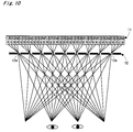
- Figure 10 is a descriptive diagram illustrating a principle of a stereoscopic image display of a four-viewpoint stereoscopic vision method.
- An image 1 ⁇ , an image 2 ⁇ , an image 3 ⁇ , and an image 4 ⁇ having the binocular parallax are aligned in a horizontal direction of a screen 11 at a predetermined pitch, and a minimum unit image group of the "image 1 ⁇ , image 2 ⁇ , image 3 ⁇ , and image 4 ⁇ " exists repeatedly.
- Each aperture 12a of a parallax barrier 12 exists corresponding to each minimum unit image group, and separates the "image 1 ⁇ , image 2 ⁇ , image 3 ⁇ , and image 4 ⁇ ", i.e., each minimum unit image group, so as to be applied to the observer. This allows the observer to perform the stereoscopic vision.
- Figure 11 is a descriptive diagram illustrating a principle of an image display allowing each of different observers to see each of four different images.
- This image display is formed of the screen 11, and the parallax barrier 12.
- Each aperture 12a of the parallax barrier 12 separates the "image 1 ⁇ , image 2 ⁇ , image 3 ⁇ , and image 4 ⁇ ", i.e., each minimum unit image group, so as to be applied to the observer. This results in each observer seeing the different images to one another.
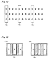
- the apertures 12a of the parallax barrier 12, as shown in Figure 12 are generally formed in a vertical stripe shape.
- the apertures of the parallax barrier are aligned in an oblique direction (see Japanese Patent No. 3096613).
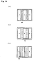
- the aperture 12a In order to reduce the moire, as shown in Figure 14, the aperture 12a needs to be rendered large.
- the large aperture 12a as shown in Figures 14 (a), (b), and (c), even if a position relationship between the dot and the aperture 12a is changed, introduces an approximately same amount of light to the eye of the observer, and therefore, a difference between the bright portion and the dark portion is decreased, thus, the moire is reduced.
- the large aperture 12a is adopted, a cross-talk is brought about.
- a width of the aperture 12a needs to be about 0.08 millimeters in order to reduce the moire, and toward such the dot, a relatively large aperture increases the cross-talk.
- a manner of a diffraction changes in the course of a transition from Figure 14 (a) to 14 (c), thus not possible to sufficiently reduce the moire.
- an object of the present invention to solve by devising an aperture (separating element) of a separating means, and others various kinds of dissatisfaction and inconvenience in an image display.
- an image display of the present invention is an image display that separates by a separating means respectively different images displayed on a screen so as to be introduced to an observer, and that one separating element exists corresponding to a minimum unit image group responsible for displaying the different images, and oblique line portions, which are non-parallel to a contour of a dot, exist in a contour of each separating element.
- the oblique line portion solves a dissatisfaction and inconvenience in the image display, which includes to prevent a disconnection of a transparent electrode, and so forth.
- the minimum unit image groups exist in such a manner as to be deviated in a horizontal direction by each one dot on each line, and the separating elements are formed corresponding to this deviation (Hereinafter, referred to as an oblique barrier configuration in this section).
- the number of viewpoints are set to be larger than two, and the separating element has a shape having intervals with dots for another image in an oblique direction wider than intervals with dots for the same image in an oblique direction.
- oblique line portions exist on vertical-direction sides, and separating element clusters to be aligned in the oblique direction may be joined to one another.
- the oblique line portions of each separating element are preferably configured in such a manner as not to be aligned on a straight line.
- it may be configured such that a pitch between dots is equal to or less than 0.08 millimeters, and the oblique line portions of each separating element is aligned on a straight line.
- oblique line portions exist on vertical-direction sides, the separating element clusters to be aligned in an oblique direction are not joined to one another, and the oblique line portions of each separating element are aligned on a straight line.
- the minimum unit image groups exist in such a manner as not to be deviated on each line, and the separating elements are formed corresponding to this non-deviation (Hereinafter, referred to as a vertical barrier configuration in this section).
- a vertical barrier configuration it may be possible that oblique line portions exist on vertical-direction sides, and separating element clusters to be aligned in a vertical direction are joined to one another.
- the separating element has a rectangular shape, and oblique line portions exist both on the vertical-direction sides and horizontal-direction sides.
- the separating element may have curved lines as the oblique line portion.
- the oblique line portions are preferably located on dots in all position relationships possibly established by the separating element and the dots, and this enables to average an influence of a diffraction of light, thus being ideal in terms of a moire reduction.
- a length of a horizontal component between an upper-side portion center and a lower-side portion center of the separating element may be equal to a horizontal dot pitch.
- a length of a vertical component between a right-side portion center and a left-side portion center of the separating element may be equal to a vertical dot pitch.
- the separating element may be an element formed of the aperture. Or, the separating element may be an element formed of a lens element.
- the separating mean is formed of a liquid crystal panel and capable of switching between a separation and a non-separation, and as a result of corners of the aperture portion that is the separating portion formed in a transparent electrode portion of the liquid crystal panel being cut-off, the oblique line portions exist. According to the above, corners of each aperture obliquely adjacent are cut-off, thus possible to prevent an isolated portion (disconnected portion) from being created in a transparent electrode portion.
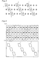
- each aperture 1 exists corresponding to each minimum unit image group, and in a contour of each aperture 1, as shown in Figure 2, oblique line portions that are non-parallel to a contour of each of the dots (R, G, B).
- Each aperture 1 shown in Figure 1 and Figures 2 (a), (b), and (c) has a parallelogram shape, and the oblique line portions exist on vertical-direction sides.
- an upper right corner coincides with an upper right corner of a center dot
- a lower right corner coincides with a lower left corner of the adjacent dot on the right
- an upper left corner coincides with an upper right corner of the adjacent dot on the left
- a lower left corner coincides with a lower left corner of the center dot.
- an upper right corner coincides with an upper left corner of the center dot
- a lower right corner coincides with a lower left corner of the adjacent dot on the right
- an upper left corner coincides with an upper right cornmer of the adjacent dot on the left
- a lower left corner coincides with a lower right corner of the center dot.
- an upper right corner coincides with an upper-side center of the center dot
- a lower right corner coincides with a lower-side center of the adjacent dot on the right
- an upper left corner coincides with an upper-side center of the adjacent dot on the left
- a lower left corner coincides with a lower-side center of the center dot.
- each apertures 1 the oblique line portions exist on the contour of the aperture, and the apertures 1 shown in Figures 2 (a), (b), and (c) are utilized.
- the oblique barrier method it may be configured that a leaked light from another dot in which an image of a viewpoint far from a certain viewpoint is displayed is difficult to enter (with respect to a dot of the image 1 ⁇ , a dot of the image 3 ⁇ is the above-described other dot, for example).
- the aperture 1 has the upper left corner and the lower right corner protruding toward a vertical side, and the upper right corner and the lower left corner not protruding, thus possible to prevent the above-described leaked light from being entered thereon.
- the aperture 1 may adopt shapes shown in Figures 5 (a), and (b).
- the aperture 1 may also adopt a shape of a ">" (a certain modified hexagon) as shown in Figure 5 (c).
- the aperture 1 may adopt a shape having curved lines as the oblique line portions, and any oblique line portion that renders smooth a change of luminance as a result of a relative position between each aperture 1 and the dot being changed may be adopted.
- the apertures 1 from Figure 5 (a) to Figure (e) are also usable in the configuration in Figure 1.
- the aperture 1 has a rectangular shape, and the oblique line portions exist both on the vertical-direction sides and the horizontal-direction sides. Such the aperture 1 is also usable in the configuration in Figure 1.
- the oblique line portions exist on the vertical-direction sides of each aperture, aperture clusters 1 ⁇ to be aligned in the oblique direction are joined to one another, and the oblique line portions of each aperture 1 are not to be aligned on a straight line.
- structure in which the apertures are joined to one another is also applicable to the configuration in Figure 1.
- the narrower the dot pitch the smaller an unevenness in positions in which the apertures are joined. It is easier to perform a designing capable of implementing both a cross-talk prevention and a moire prevention in a case that there is the unevenness, albeit small.
- the pitch between dots is equal to or less than 0.08 millimeters
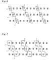
- each aperture 1 is not joined to each other, thus independent to each other.
- the oblique stripe it is not possible to set a condensing position of the vertical direction.
- the configuration in Figure 8 having the apertures in such a manner as to be independent to one another, it is possible to set the condensing position of the vertical direction.
- a configuration shown in Figure 9 is a configuration in which a barrier state and a non-barrier state are formable by constituting the barrier of the liquid crystal panel, for example, in the oblique dot arrangement shown in Figure 3, and others.
- a portion in black in Figure 9 is a transparent electrode forming area, and portions in white are the apertures 1 at a time of the barrier.
- the aperture 1 is an aperture that has the oblique line portions, and as a result of corners of a square shape being cut-off, and the corners are thus cut-off like this so that it becomes possible to prevent an isolated portion (disconnected portion) from being formed in the transparent electrode portion.
- the image separation by the apertures is shown.
- a lens element may be used instead of the aperture.
- it may be configured such that the separating means is arranged on a light-source side.
- the oblique line portions exist on the contour of the separating element, and depending on a manner of the oblique line portions, a change of luminance as a result of the relative position between each separating element and the dot being changed is rendered smooth.
- the present invention brings about desirable effects such as the oblique line portion preventing the transparent electrode from being disconnected.
Landscapes
- Engineering & Computer Science (AREA)
- Multimedia (AREA)
- Signal Processing (AREA)
- Physics & Mathematics (AREA)
- General Physics & Mathematics (AREA)
- Theoretical Computer Science (AREA)
- Business, Economics & Management (AREA)
- Accounting & Taxation (AREA)
- Marketing (AREA)
- Liquid Crystal (AREA)
Applications Claiming Priority (3)
| Application Number | Priority Date | Filing Date | Title |
|---|---|---|---|
| JP2002324428 | 2002-11-07 | ||
| JP2002324428A JP2004157411A (ja) | 2002-11-07 | 2002-11-07 | 映像表示装置 |
| PCT/JP2003/012178 WO2004042452A1 (ja) | 2002-11-07 | 2003-09-24 | 映像表示装置 |
Publications (1)
| Publication Number | Publication Date |
|---|---|
| EP1569026A1 true EP1569026A1 (de) | 2005-08-31 |
Family
ID=32310446
Family Applications (1)
| Application Number | Title | Priority Date | Filing Date |
|---|---|---|---|
| EP03810582A Withdrawn EP1569026A1 (de) | 2002-11-07 | 2003-09-24 | Bildanzeigeeinheit |
Country Status (6)
| Country | Link |
|---|---|
| US (1) | US20060114561A1 (de) |
| EP (1) | EP1569026A1 (de) |
| JP (1) | JP2004157411A (de) |
| KR (1) | KR20050084957A (de) |
| CN (1) | CN1323315C (de) |
| WO (1) | WO2004042452A1 (de) |
Cited By (3)
| Publication number | Priority date | Publication date | Assignee | Title |
|---|---|---|---|---|
| WO2007107347A1 (de) * | 2006-03-21 | 2007-09-27 | Newsight Gmbh | Anordnung zur räumlich wahrnehmbaren darstellung |
| EP1995977A3 (de) * | 2007-05-23 | 2013-01-02 | Seiko Epson Corporation | Generator, Anzeigevorrichtung, Erzeugungsverfahren und Anzeigeverfahren für stereoskopische Bilder |
| EP3067733A1 (de) * | 2015-03-12 | 2016-09-14 | LG Display Co., Ltd. | Stereopsis-anzeigevorrichtung |
Families Citing this family (31)
| Publication number | Priority date | Publication date | Assignee | Title |
|---|---|---|---|---|
| JP3892808B2 (ja) * | 2002-12-27 | 2007-03-14 | 株式会社東芝 | 3次元画像表示装置、この表示装置に視差画像を配分する方法及びこの表示装置に3次元画像を表示する方法 |
| JP3955002B2 (ja) * | 2003-09-09 | 2007-08-08 | 三洋電機株式会社 | 映像表示装置 |
| DE102004028951A1 (de) * | 2004-06-14 | 2005-12-29 | X3D Technologies Gmbh | Anordnung zur räumlichen Darstellung |
| GB2415850A (en) * | 2004-06-29 | 2006-01-04 | Sharp Kk | Multiple view directional display operable in two orientations. |
| FR2873824B1 (fr) * | 2004-07-30 | 2006-10-27 | Pierre Allio | Procede d'affichage d'une image autostereoscopique a n points de vue |
| JP2006091642A (ja) * | 2004-09-27 | 2006-04-06 | Sanyo Electric Co Ltd | 映像表示装置 |
| KR100910969B1 (ko) | 2005-01-05 | 2009-08-05 | 엘지전자 주식회사 | 입체 영상 표시 방법 및 그 방법을 위한 입체 영상 표시장치 |
| KR100753517B1 (ko) * | 2005-10-12 | 2007-08-31 | 엘지전자 주식회사 | 입체 영상 디스플레이 기능을 갖는 이동통신 단말기 및이를 이용한 입체 영상 디스플레이 방법 |
| KR100662429B1 (ko) * | 2005-11-01 | 2007-01-02 | 엘지전자 주식회사 | 입체 영상 표시 장치 |
| CN101331776B (zh) | 2005-12-13 | 2013-07-31 | 皇家飞利浦电子股份有限公司 | 显示设备 |
| KR100745460B1 (ko) * | 2006-06-28 | 2007-08-02 | 비오이 하이디스 테크놀로지 주식회사 | 입체영상구현용 액정표시장치 |
| JP2009053585A (ja) * | 2007-08-29 | 2009-03-12 | Seiko Epson Corp | 電気光学装置及び電子機器 |
| US20090128900A1 (en) * | 2007-11-15 | 2009-05-21 | Idyllic Spectrum Sdn Bhd | Autostereoscopic display |
| KR100927822B1 (ko) * | 2007-11-16 | 2009-11-23 | 주식회사 히가리이노비젼 | 동영상 구현이 가능한 페럴랙스 배리어 방식의 입체 영상 표시장치 |
| CN100595631C (zh) * | 2008-04-18 | 2010-03-24 | 浙江大学 | 实现全视场空间三维显示的屏幕装置 |
| JP2010020178A (ja) * | 2008-07-11 | 2010-01-28 | Epson Imaging Devices Corp | 画像表示装置、画像表示方法及び画像表示プログラム |
| JPWO2010007787A1 (ja) * | 2008-07-15 | 2012-01-05 | 吉田 健治 | 裸眼立体映像表示システム、裸眼立体映像表示装置、遊技ゲーム機、パララックスバリアシート |
| JP5512158B2 (ja) * | 2009-03-31 | 2014-06-04 | 株式会社ジャパンディスプレイ | 表示装置 |
| GB2470752B (en) * | 2009-06-03 | 2015-01-07 | Au Optronics Corp | Autostereoscopic Display Apparatus |
| WO2011058967A1 (ja) * | 2009-11-12 | 2011-05-19 | ネプラス株式会社 | パララックスバリアフィルタ |
| US9432658B2 (en) | 2011-06-20 | 2016-08-30 | Panasonic Intellectual Property Corporation Of America | Image display device |
| JP2015034834A (ja) | 2011-11-30 | 2015-02-19 | シャープ株式会社 | 立体表示装置 |
| KR101990490B1 (ko) | 2012-06-18 | 2019-06-19 | 삼성디스플레이 주식회사 | 입체 영상 표시 장치 및 그 구동 방법 |
| JP6099892B2 (ja) * | 2012-07-09 | 2017-03-22 | パナソニック インテレクチュアル プロパティ コーポレーション オブ アメリカPanasonic Intellectual Property Corporation of America | 映像表示装置 |
| KR102316982B1 (ko) * | 2015-03-12 | 2021-10-27 | 엘지디스플레이 주식회사 | 입체 영상 디스플레이 장치 |
| CN105093545B (zh) * | 2015-08-12 | 2018-07-10 | 京东方科技集团股份有限公司 | 3d显示面板和3d显示方法以及显示装置 |
| KR102401202B1 (ko) | 2015-09-11 | 2022-05-24 | 삼성전자주식회사 | 광학 레이어, 이를 포함하는 디스플레이 장치 및 백라이트 유닛 |
| CN105572886B (zh) * | 2016-01-26 | 2018-12-11 | 京东方科技集团股份有限公司 | 一种三维显示装置 |
| KR102522397B1 (ko) * | 2016-11-29 | 2023-04-17 | 엘지디스플레이 주식회사 | 무안경 방식의 입체영상 표시장치 |
| JP2021056254A (ja) * | 2019-09-26 | 2021-04-08 | 京セラ株式会社 | パララックスバリア、3次元表示装置、3次元表示システム、ヘッドアップディスプレイ、および移動体 |
| JP2022156858A (ja) * | 2021-03-31 | 2022-10-14 | 株式会社ジャパンディスプレイ | 表示装置 |
Family Cites Families (5)
| Publication number | Priority date | Publication date | Assignee | Title |
|---|---|---|---|---|
| JPH08101367A (ja) * | 1994-08-05 | 1996-04-16 | Sanyo Electric Co Ltd | 立体画像表示装置 |
| JP2966762B2 (ja) * | 1995-05-30 | 1999-10-25 | 三洋電機株式会社 | 立体表示装置 |
| JP3096613B2 (ja) * | 1995-05-30 | 2000-10-10 | 三洋電機株式会社 | 立体表示装置 |
| US6064424A (en) * | 1996-02-23 | 2000-05-16 | U.S. Philips Corporation | Autostereoscopic display apparatus |
| JP4068188B2 (ja) * | 1997-09-02 | 2008-03-26 | 富士通株式会社 | 画像表示装置 |
-
2002
- 2002-11-07 JP JP2002324428A patent/JP2004157411A/ja active Pending
-
2003
- 2003-09-24 US US10/534,121 patent/US20060114561A1/en not_active Abandoned
- 2003-09-24 KR KR1020057008034A patent/KR20050084957A/ko not_active Withdrawn
- 2003-09-24 WO PCT/JP2003/012178 patent/WO2004042452A1/ja not_active Ceased
- 2003-09-24 EP EP03810582A patent/EP1569026A1/de not_active Withdrawn
- 2003-09-24 CN CNB038246651A patent/CN1323315C/zh not_active Expired - Fee Related
Non-Patent Citations (1)
| Title |
|---|
| See references of WO2004042452A1 * |
Cited By (4)
| Publication number | Priority date | Publication date | Assignee | Title |
|---|---|---|---|---|
| WO2007107347A1 (de) * | 2006-03-21 | 2007-09-27 | Newsight Gmbh | Anordnung zur räumlich wahrnehmbaren darstellung |
| EP1995977A3 (de) * | 2007-05-23 | 2013-01-02 | Seiko Epson Corporation | Generator, Anzeigevorrichtung, Erzeugungsverfahren und Anzeigeverfahren für stereoskopische Bilder |
| EP3067733A1 (de) * | 2015-03-12 | 2016-09-14 | LG Display Co., Ltd. | Stereopsis-anzeigevorrichtung |
| US9807376B2 (en) | 2015-03-12 | 2017-10-31 | Lg Display Co., Ltd. | Stereopsis display device |
Also Published As
| Publication number | Publication date |
|---|---|
| WO2004042452A1 (ja) | 2004-05-21 |
| US20060114561A1 (en) | 2006-06-01 |
| CN1323315C (zh) | 2007-06-27 |
| KR20050084957A (ko) | 2005-08-29 |
| CN1695077A (zh) | 2005-11-09 |
| JP2004157411A (ja) | 2004-06-03 |
Similar Documents
| Publication | Publication Date | Title |
|---|---|---|
| EP1569026A1 (de) | Bildanzeigeeinheit | |
| CN100526937C (zh) | 图像显示装置 | |
| US6970290B1 (en) | Stereoscopic image display device without glasses | |
| US7834903B2 (en) | Stereoscopic display device and display method | |
| CN101049028B (zh) | 多视图显示器 | |
| US8553074B2 (en) | Auto stereoscopic display improving brightness | |
| EP0779531B1 (de) | Stereoskopisches Anzeigesystem | |
| JP2001166259A (ja) | 眼鏡無し立体映像表示装置 | |
| JP2004206089A (ja) | マルチプル視野ディスプレイ | |
| CN101398608A (zh) | 立体影像显示装置以及立体影像显示方法 | |
| KR20090031767A (ko) | 입체영상 표시장치 및 입체영상 표시방법 | |
| US20070152997A1 (en) | Display panel for 3-dimensional display device and 3-dimensional display device comprising the same | |
| US20120113510A1 (en) | Display device and display method | |
| KR101329962B1 (ko) | 입체영상 표시장치 | |
| JP2005258013A (ja) | 表示パネルおよび表示装置 | |
| KR20150055442A (ko) | 입체 영상 표시 장치 | |
| US9256076B2 (en) | Image display device | |
| JP2004264762A (ja) | 立体映像表示装置 | |
| KR100828696B1 (ko) | 가변형 패럴렉스 배리어와 이를 이용한 입체 영상 표시장치 | |
| JP3234354B2 (ja) | 投写型映像表示装置 | |
| JP2006091642A (ja) | 映像表示装置 | |
| CN114885148B (zh) | 立体显示系统的显示方法及立体显示系统 | |
| JPH09211387A (ja) | 立体画像表示装置 | |
| JP2012242544A (ja) | 表示装置 |
Legal Events
| Date | Code | Title | Description |
|---|---|---|---|
| PUAI | Public reference made under article 153(3) epc to a published international application that has entered the european phase |
Free format text: ORIGINAL CODE: 0009012 |
|
| 17P | Request for examination filed |
Effective date: 20050506 |
|
| AK | Designated contracting states |
Kind code of ref document: A1 Designated state(s): DE FR GB |
|
| STAA | Information on the status of an ep patent application or granted ep patent |
Free format text: STATUS: THE APPLICATION IS DEEMED TO BE WITHDRAWN |
|
| 18D | Application deemed to be withdrawn |
Effective date: 20070401 |