EP1568981B1 - Procédé de mesure d'une quantité physique employant un capteur de Brillouin à fibre optique. - Google Patents
Procédé de mesure d'une quantité physique employant un capteur de Brillouin à fibre optique. Download PDFInfo
- Publication number
- EP1568981B1 EP1568981B1 EP05003611A EP05003611A EP1568981B1 EP 1568981 B1 EP1568981 B1 EP 1568981B1 EP 05003611 A EP05003611 A EP 05003611A EP 05003611 A EP05003611 A EP 05003611A EP 1568981 B1 EP1568981 B1 EP 1568981B1
- Authority
- EP
- European Patent Office
- Prior art keywords
- frequency
- light
- back scattering
- pulse
- optical fiber
- Prior art date
- Legal status (The legal status is an assumption and is not a legal conclusion. Google has not performed a legal analysis and makes no representation as to the accuracy of the status listed.)
- Not-in-force
Links
- 239000013307 optical fiber Substances 0.000 title claims abstract description 103
- 238000000034 method Methods 0.000 title claims abstract description 48
- 238000001228 spectrum Methods 0.000 claims abstract description 93
- 239000000523 sample Substances 0.000 claims description 52
- 238000012935 Averaging Methods 0.000 claims description 34
- 238000005259 measurement Methods 0.000 claims description 7
- 238000005070 sampling Methods 0.000 claims description 3
- 238000005086 pumping Methods 0.000 description 14
- 238000009826 distribution Methods 0.000 description 10
- 238000009825 accumulation Methods 0.000 description 9
- 238000003672 processing method Methods 0.000 description 4
- 239000000835 fiber Substances 0.000 description 3
- 230000003321 amplification Effects 0.000 description 2
- 238000010276 construction Methods 0.000 description 2
- 230000003247 decreasing effect Effects 0.000 description 2
- 230000002708 enhancing effect Effects 0.000 description 2
- 238000003199 nucleic acid amplification method Methods 0.000 description 2
- 230000003287 optical effect Effects 0.000 description 2
- 238000004458 analytical method Methods 0.000 description 1
- 239000007789 gas Substances 0.000 description 1
- 239000007788 liquid Substances 0.000 description 1
- 230000010355 oscillation Effects 0.000 description 1
- 230000000630 rising effect Effects 0.000 description 1
- 239000007787 solid Substances 0.000 description 1
- 230000003068 static effect Effects 0.000 description 1
Images


Classifications
-
- G—PHYSICS
- G01—MEASURING; TESTING
- G01B—MEASURING LENGTH, THICKNESS OR SIMILAR LINEAR DIMENSIONS; MEASURING ANGLES; MEASURING AREAS; MEASURING IRREGULARITIES OF SURFACES OR CONTOURS
- G01B11/00—Measuring arrangements characterised by the use of optical techniques
- G01B11/16—Measuring arrangements characterised by the use of optical techniques for measuring the deformation in a solid, e.g. optical strain gauge
- G01B11/18—Measuring arrangements characterised by the use of optical techniques for measuring the deformation in a solid, e.g. optical strain gauge using photoelastic elements
-
- G—PHYSICS
- G01—MEASURING; TESTING
- G01D—MEASURING NOT SPECIALLY ADAPTED FOR A SPECIFIC VARIABLE; ARRANGEMENTS FOR MEASURING TWO OR MORE VARIABLES NOT COVERED IN A SINGLE OTHER SUBCLASS; TARIFF METERING APPARATUS; MEASURING OR TESTING NOT OTHERWISE PROVIDED FOR
- G01D5/00—Mechanical means for transferring the output of a sensing member; Means for converting the output of a sensing member to another variable where the form or nature of the sensing member does not constrain the means for converting; Transducers not specially adapted for a specific variable
- G01D5/26—Mechanical means for transferring the output of a sensing member; Means for converting the output of a sensing member to another variable where the form or nature of the sensing member does not constrain the means for converting; Transducers not specially adapted for a specific variable characterised by optical transfer means, i.e. using infrared, visible, or ultraviolet light
- G01D5/32—Mechanical means for transferring the output of a sensing member; Means for converting the output of a sensing member to another variable where the form or nature of the sensing member does not constrain the means for converting; Transducers not specially adapted for a specific variable characterised by optical transfer means, i.e. using infrared, visible, or ultraviolet light with attenuation or whole or partial obturation of beams of light
- G01D5/34—Mechanical means for transferring the output of a sensing member; Means for converting the output of a sensing member to another variable where the form or nature of the sensing member does not constrain the means for converting; Transducers not specially adapted for a specific variable characterised by optical transfer means, i.e. using infrared, visible, or ultraviolet light with attenuation or whole or partial obturation of beams of light the beams of light being detected by photocells
- G01D5/353—Mechanical means for transferring the output of a sensing member; Means for converting the output of a sensing member to another variable where the form or nature of the sensing member does not constrain the means for converting; Transducers not specially adapted for a specific variable characterised by optical transfer means, i.e. using infrared, visible, or ultraviolet light with attenuation or whole or partial obturation of beams of light the beams of light being detected by photocells influencing the transmission properties of an optical fibre
- G01D5/35338—Mechanical means for transferring the output of a sensing member; Means for converting the output of a sensing member to another variable where the form or nature of the sensing member does not constrain the means for converting; Transducers not specially adapted for a specific variable characterised by optical transfer means, i.e. using infrared, visible, or ultraviolet light with attenuation or whole or partial obturation of beams of light the beams of light being detected by photocells influencing the transmission properties of an optical fibre using other arrangements than interferometer arrangements
- G01D5/35341—Sensor working in transmission
- G01D5/35348—Sensor working in transmission using stimulated emission to detect the measured quantity
-
- G—PHYSICS
- G01—MEASURING; TESTING
- G01K—MEASURING TEMPERATURE; MEASURING QUANTITY OF HEAT; THERMALLY-SENSITIVE ELEMENTS NOT OTHERWISE PROVIDED FOR
- G01K11/00—Measuring temperature based upon physical or chemical changes not covered by groups G01K3/00, G01K5/00, G01K7/00 or G01K9/00
- G01K11/32—Measuring temperature based upon physical or chemical changes not covered by groups G01K3/00, G01K5/00, G01K7/00 or G01K9/00 using changes in transmittance, scattering or luminescence in optical fibres
- G01K11/322—Measuring temperature based upon physical or chemical changes not covered by groups G01K3/00, G01K5/00, G01K7/00 or G01K9/00 using changes in transmittance, scattering or luminescence in optical fibres using Brillouin scattering
-
- G—PHYSICS
- G01—MEASURING; TESTING
- G01L—MEASURING FORCE, STRESS, TORQUE, WORK, MECHANICAL POWER, MECHANICAL EFFICIENCY, OR FLUID PRESSURE
- G01L1/00—Measuring force or stress, in general
- G01L1/24—Measuring force or stress, in general by measuring variations of optical properties of material when it is stressed, e.g. by photoelastic stress analysis using infrared, visible light, ultraviolet
- G01L1/242—Measuring force or stress, in general by measuring variations of optical properties of material when it is stressed, e.g. by photoelastic stress analysis using infrared, visible light, ultraviolet the material being an optical fibre
-
- G—PHYSICS
- G01—MEASURING; TESTING
- G01M—TESTING STATIC OR DYNAMIC BALANCE OF MACHINES OR STRUCTURES; TESTING OF STRUCTURES OR APPARATUS, NOT OTHERWISE PROVIDED FOR
- G01M11/00—Testing of optical apparatus; Testing structures by optical methods not otherwise provided for
- G01M11/08—Testing mechanical properties
- G01M11/083—Testing mechanical properties by using an optical fiber in contact with the device under test [DUT]
- G01M11/085—Testing mechanical properties by using an optical fiber in contact with the device under test [DUT] the optical fiber being on or near the surface of the DUT
-
- G—PHYSICS
- G01—MEASURING; TESTING
- G01K—MEASURING TEMPERATURE; MEASURING QUANTITY OF HEAT; THERMALLY-SENSITIVE ELEMENTS NOT OTHERWISE PROVIDED FOR
- G01K2213/00—Temperature mapping
Definitions
- the present invention relates to a method of measuring a physical variation in a static structure (a bridge, a building and so on) or a dynamic structure (an airplane, a vehicle and so on) using an optical fiber and Brillouin scattering of the optical fiber. More specifically, the invention relates to a physical quantity measuring method using a Brillouin optical fiber sensor, which is able to measure a physical quantity and its distribution of a corresponding structure with improved spatial resolution using two pulse lights and two back scattering lights acquired from the pulse lights.
- Brillouin scattering relates to a sound wave generated according to movement of molecules physically excited in a gas, liquid or solid.
- a Brillouin optical fiber sensor using the Brillouin scattering of an optical fiber.
- the Brillouin sensor has a structure that a pulse light is reacted with an oscillating wave inside an optical fiber when the pulse light is transmitted through the optical fiber such that the pulse light is scattered at a frequency different from the frequency of the original pulse light. If a specific physical quantity (heat, load and so on) is applied to the optical fiber, molecules of the optical fiber, which are excited due to the physical quantity, form a sound wave and act on the pulse light.
- the scattered pulse light has a frequency different from the frequency of the pulse light when the pulse light is input to the optical fiber.
- the physical quantity can be measured by detecting the frequency of the scattered pulse light.
- the Brillouin optical fiber sensor can be utilized as a sensing structure.
- FIG. 1 shows the construction of a conventional Brillouin sensor and FIG. 2 shows a Brillouin gain spectrum obtained by measuring temperature distribution of a specific structure using the sensor of FIG. 1 .
- first and second light sources 20 and 30 are respectively arranged at both ends of an optical fiber 10, opposite to each other.
- the first light source 20 arranged at one end of the optical fiber 10 transmits a pumping pulse light to the other end of the optical fiber 10.
- the second light source 30 located at the other end of the optical fiber 10 transmits a continuous wave probe light to one end of the optical fiber 10.
- a portion of the optical fiber 10, exposed between the first and second light sources 20 and 30, is attached to a specific structure (a building, a bridge and so on, for instance) to serve as a sensing part.
- the portion of the optical fiber 10, which is attached to the structure functions as a sensing structure.
- the frequency of scattered light transmitted in response to a variation in the temperature of the structure can be compared with a difference between the frequency of the pumping pulse light and the frequency of the probe light.
- a structure capable of measuring a temperature is based on the fact that the frequency of the scattered light is changed as a temperature becomes changed.
- the pumping pulse light is photo-energy-converted into the probe light and thus the probe light is amplified as Brillouin-light inside the optical fiber 10. Accordingly, analysis of Brillouin signals is facilitated.
- the amplified probe light signal is converted into an electric signal by the light receiver 40.
- the electric signal has Brillouin gain spectrum characteristic shown in FIG. 2 based on ⁇ and time detected by the light receiver.
- the Brillouin frequency value of the optical fiber 10 is changed as shown in FIG. 2 .
- the molecules of the optical fiber are thermally excited when the probe light meets the pumping pulse light to cause sound oscillation and generate Brillouin scattering light.
- This Brillouin scattering amplification is generated when the difference between the frequencies of the pumping pulse light and probe light has a specific value, which is the Brillouin frequency value.
- the Brillouin frequency value is a property of the optical fiber and it is varied in proportion to a physical quantity such as a temperature or strain.
- FIG. 2 shows the distribution of the frequency shift value based on a frequency axis, an optical intensity axis (mW) and a length (km) of the sensing part of the optical fiber 10.
- the frequency shift ⁇ is shown to 10.8 GHz, 10.85 GHz, 10.9 GHz and 10.95 GHz on the frequency axis.
- a temperature variation based on the distribution of the frequency shift is shown as a graph above the graph showing the distribution of the frequency shift. The larger the number of ⁇ frequency shifts set on the frequency axis, the more accurate the distribution of the frequency shift is.
- the conventional Brillouin sensor requires the structure in which the two light sources, that is, the first and second light sources 20 and 30, are arranged at both ends of the optical fiber 10 in order to acquire data about ⁇ and needs a very long period of time to obtain measurement results because the probe light of the second light source 30 is emitted in the form of pulse light. Accordingly, when the conventional Brillouin sensor is applied to a large structure, a factor causing a temperature variation, for example, a fire, cannot be immediately detected.
- the size (or length) of a portion of the Brillouin optical fiber sensor, affected by a physical quantity based on a measured value at an arbitrary position, is called spatial resolution.
- the spatial resolution of an optical fiber sensor is 1m, for example, it means that a single sensing signal is obtained within 1m of a corresponding portion of the optical fiber. It is known that the spatial resolution is directly proportional to the width of the pumping pulse light in the optical fiber sensor structure.
- a portion of the optical fiber, in which pumping pulse light is back-scattered, corresponds to half of the length of the optical fiber, occupied by the pumping pulse light.
- the spatial resolution becomes 1m (that is equal to 200,000 km/s x 10 nsec x 1/2) considering that the velocity of light transmitted inside the optical fiber is approximately 200,000 km/s.
- a signal having the spatial resolution of 1m is obtained when the optical fiber sensor is operated using the pumping pulse light with the pulse width of 10 nsec.
- it is required to operate the optical fiber sensor with smaller spatial resolution. In this case, however, the scattering light is decreased because the energy of the pumping pulse light is reduced.
- the Brillouin scattering light amplification occurs only when a pulse light with a pulse width of at least 10 nsec is used and it is difficult to determine a gain peak with a pulse width of less than 50 nsec because the line width of the Brillouin scattering spectrum is remarkably increased.
- EP 0 907 073 A1 discloses a method for measuring a physical quantity using a Brillouin optical fibre sensor. It already discloses transmitting two light signals with different pulse widths sequentially down the fibre. It is the object of the invention to improve the method of EP-A-0 907 073 .
- the present invention is directed to a physical quantity measuring method using a Brillouin optical fiber sensor that substantially obviate one or more problems due to limitations and disadvantages of the related art.
- An object of the present invention is to provide a physical quantity measuring method using a Brillouin optical fiber sensor, which is able to measure a physical quantity by using a pair of pulse lights having different pulse widths and comparing obtained gain spectra with each other.
- Another object of the present invention is to provide a physical quantity measuring method using a Brillouin optical fiber sensor, which obtains a normal spectrum with a short back scattering light accumulation length by comparing obtained gain spectra with each other and measures a physical quantity based on the normal spectrum to enable measurement of a sensing signal in a short optical fiber portion, to thereby remarkably enhance spatial resolution.
- the physical quantity measuring method like that may be generally realized by controller(50) in Fig. 1 .
- a physical quantity measuring method uses a Brillouin optical fiber sensor including a step S1000 of setting an optical fiber 100 on a predetermined structure as a sensing structure; a step S2000 of selecting a pair of first and second pulse lights having different pulse widths; a step S3000 of sequentially transmitting the first and second pulse lights through the optical fiber 100 to obtain Brillouin gain spectra; a step S4000 of comparing the Brillouin gain spectra with each other to obtain a normal spectrum; a step S5000 of determining a Brillouin frequency having a peak value from the normal spectrum; and a step S6000 of multiplying the Brillouin frequency by a conversion factor of a physical quantity to be measured to calculate/obtain the physical quantity.
- the step of acquiring the Brillouin gain spectra includes the steps of transmitting the first pulse light having larger pulse width through the optical fiber and transmitting a corresponding probe light to obtain a first Brillouin gain spectrum, and transmitting the second pulse light having smaller pulse width through the optical fiber and transmitting a corresponding probe light to obtain a second Brillouin gain spectrum.
- the normal spectrum is obtained by dividing the first Brillouin gain spectrum by the second Brillouin gain spectrum according to the formula in claim 1.
- the step of obtaining the first Brillouin gain spectrum includes a step S3110 of setting the frequency of the corresponding probe light to the initial frequency of a predetermined frequency checking range; a step S3120 of transmitting the first pulse light and probe light to acquire a first back scattering light; a step S3130 of repeatedly acquiring the first back scattering light by the number of averaging times previously determined and averaging the repeatedly acquired first back scattering lights; a step S3140 of judging whether the repeated acquisition of the first back scattering light by the number of averaging times is completed; a step S3150 of repeating the steps from the step of acquiring the first back scattering light when the repeated acquisition of the first back scattering light by the number of averaging times is completed, and determining whether the frequency of the probe light corresponds to the final frequency of the frequency checking range when the repeated acquisition of the first back scattering light by the number of averaging times is not completed; a step S3160 of adding a frequency corresponding to the previously determined gradual frequency increase width to the
- the step of acquiring the second Brillouin gain spectrum includes a step S3210 of setting the frequency of the corresponding probe light to the initial frequency of a predetermined frequency checking range; a step S3220 of transmitting the second pulse light and probe light to acquire a second back scattering light; a step S3230 of repeatedly acquiring the second back scattering light by the number of averaging times previously determined and averaging the repeatedly acquired second back scattering lights; a step S3240 of judging whether the repeated acquisition of the second back scattering light by the number of averaging times is completed; a step S3250 of repeating the steps from the step of acquiring the second back scattering light when the repeated acquisition of the second back scattering light by the number of averaging times is not completed, and determining whether the frequency of the probe light corresponds to the final frequency of the frequency checking range when the repeated acquisition of the second back scattering light by the number of averaging times is completed; a step S3260 of adding a frequency corresponding to the previously determined gradual frequency increase width to the
- FIG. 3 shows back scattering light accumulation lengths in a fiber for explaining signal processing according to the present invention.
- the present invention uses pulse lights having different pulse widths and compares back scattering lights obtained from the pulse lights with each other to acquire a sensing signal in shorter sensing space.
- FIG. 3 illustrates two spaces of Brillouin scattering lights obtained when two pulse lights having different pulse widths are sequentially transmitted through a single optical fiber.
- the two spaces of Brillouin scattering lights are shown at their locations in the optical fiber.
- the first Brillouin scattering light is accumulated in a space ranging from x to x+ ⁇ z 2 and the second Brillouin scattering light is accumulated in a space ranging from x to x+ ⁇ z 1 .
- a difference between the accumulated quantity of the first Brillouin scattering light and the accumulated quantity of the second Brillouin scattering light corresponds to the portion ⁇ z 2 - ⁇ z 1 .
- the difference is smaller than the accumulated quantity of each of the first and second Brillouin scattering lights and thus smaller than the magnitude of spatial resolution obtained through each Brillouin scattering light, particularly, spatial resolution represented by the length of the optical fiber.
- the present invention can improve the spatial resolution because the sensing signal can be acquired in shorter portion of the optical fiber from the difference between the Brillouin scattering lights.
- Equations 1, 2 and 3 represent the principle of signal processing of the back scattering lights for enhancing the spatial resolution according to the present invention.
- I 1 x ⁇ I L ⁇ ⁇ exp - ⁇ L ⁇ exp ⁇ x x + ⁇ ⁇ z 2 g z ⁇ ⁇ ⁇ ⁇ ⁇ I pu z ⁇ ⁇ d z ⁇
- I 2 x ⁇ I L ⁇ ⁇ exp - ⁇ ⁇ L ⁇ exp ⁇ x x + ⁇ ⁇ z 1 g z ⁇ ⁇ ⁇ ⁇ I pu z ⁇ ⁇ d z ⁇
- Equations 1 and 2 respectively represent intensities of back scattering lights obtained from the pulse lights having different pulse widths, which means Brillouin gain spectra.
- x represents the position at which each back scattering light starts and I(L, ⁇ ) means the intensity of each back scattering light.
- L is the length of the optical fiber and a denotes the attenuation coefficient of the optical fiber.
- g(z', ⁇ ) represents a Brillouin gain factor and ⁇ I pu (z', ⁇ ) means the intensity of each pulse light.
- Equations 1 and 2 the range of each integral calculus has a difference corresponding to ⁇ z 2 - ⁇ z 1 .
- Integral calculus from x to x+ ⁇ z 1 is included in each of Equations 1 and 2.
- the integral calculus from x to x+ ⁇ z 1 is eliminated when the second Brillouin gain spectrum is divided by the first Brillouin gain spectrum as represented by Equation 3 and thus a normal Brillouin gain spectrum is obtained.
- NBGS(x, ⁇ ) represents the normal Brillouin gain spectrum. That is, NBGS(x, ⁇ ) means back scattering light accumulated in the portion ⁇ z 2 - ⁇ z 1 , which corresponds to the difference between the two back scattering lights.
- a Brillouin frequency obtained through the aforementioned signal processing can be used for calculating a corresponding physical quantity when multiplied by a conversion factor with respect to the physical quantity.
- the signal processing method according to the present invention carried out through the above-described equations, is utilized, spatial resolution corresponding to 1m or less of the optical fiber can be achieved while using a pulse width sufficiently larger than 10 nsec that is a critical value of generating a Brillouin gain. Furthermore, the normal Brillouin gain spectrum NBGS has reduced the broadening of the spectrum linewidth and the decreasing of the spectrum gain, when the spatial resolution is less than 5m. Accordingly, in the case where a pulse light can be modulated into a pulse signal having very short rising time and falling time, spatial resolution can be reduced to less than 1m through the signal processing method according to the present invention.
- FIG. 4 is a flow chart showing the physical quantity measuring method using a Brillouin optical fiber sensor according to the present invention.
- the measuring method according to the present invention sets/selects a pair of pulse lights having different pulse widths and processes back scattering lights obtained when the pulse lights are transmitted through the same optical fiber using the aforementioned signal processing method. Then, a difference between the back scattering lights can be calculated as a ratio of gain spectra and a Brillouin frequency can be obtained based on a normal gain spectrum acquired from the ratio of gain spectra. A physical quantity can be measured from the Brillouin frequency.
- the Brillouin frequency is obtained using the ratio of gain spectra and calculated based on the difference between the back scattering lights so that the Brillouin frequency is smaller than the frequency of each back scattering light or each gain spectrum. Accordingly, a sensing signal can be easily acquired in shorter portion of the optical fiber.
- an optical fiber is set on a specific structure (for example, a building, a bridge, an airplane, a ship and so on) as a Brillouin sensing structure using a known method in the step S1000.
- the optical fiber has a single strand, which is branched from a coupler structure and returned to the coupler structure.
- fundamental parameters including the number of averaging times, the number of samplings, a sampling rate, a frequency checking range, a gradual frequency increase space and so on are determined in advance. Then, arrangement for transmitting the pulse lights is finished.
- a pair of first and second pulse lights having different pulse width is selected.
- the pulse width of the first pulse light is larger than the pulse width of the second pulse light.
- the pulse widths of the first and second pulse lights and/or a difference between the two pulse widths determine spatial resolution. Accordingly, it is preferable to previously select the pulse widths of the pulse lights based on the size (particularly, area) of the corresponding structure, arrangement structure of a sensed part of the optical fiber, and physical quantity to be sensed (temperature, load or strain).
- the first and second pulse lights are sequentially transmitted through the optical fiber to obtain first and second back scattering lights.
- a first Brillouin gain spectrum and a second Brillouin gain spectrum are acquired based on the obtained first and second back scattering lights in the step S3000.
- the first pulse light having larger pulse width is transmitted from one side of the optical fiber.
- a continuous wave probe light is transmitted from the other side of the optical fiber and a specific physical quantity acts on the optical fiber.
- the first back scattering light having relatively large accumulation space is obtained, as described with reference to FIG. 3 .
- the first Brillouin gain spectrum is obtained using Equation 1 in the step S3100.
- the second pulse light is transmitted from one side of the optical fiber.
- Brillouin scattering due to a probe light is generated in response to a corresponding physical quantity and thus the second back scattering light having an accumulation space smaller than that of the first back scattering light is obtained.
- the second Brillouin gain spectrum is obtained using Equation 2 in the step S3200. Consequently, the first and second Brillouin gain spectra are acquired using the first and second pulse lights.
- a normal spectrum is obtained from the first and second Brillouin gain spectra using Equation 3. Specifically, the first Brillouin gain spectrum having larger accumulation space is divided by the second Brillouin gain spectrum having smaller accumulation space to obtain the normal spectrum corresponding to the ratio of the first Brillouin gain spectrum to the second Brillouin gain spectrum in the step S4000.
- a frequency with maximum power that is, a Brillouin frequency
- the Brillouin frequency is determined by a difference between the accumulation spaces of the first and second back scattering lights, that is, a portion smaller than the accumulation space of each back scattering light and thus enhanced spatial resolution can be provided.
- the Brillouin frequency is multiplied by a conversion factor of a corresponding physical quantity to finally obtain the physical quantity in the step S6000.
- FIGS. 5a and 5b are flow charts respectively showing the steps of obtaining the first and second Brillouin gain spectra shown in FIG. 4 .
- the frequency of the probe light is set to the initial frequency value of the frequency checking range determined at the fundamental parameter determining step in the steps S3110 and S3210. Then, the first and second pulse lights and probe light are transmitted through the optical fiber to obtain the first and second back scattering lights in the steps S3120 and S3220.
- an averaging process that repeatedly acquires the back scattering lights by the number of averaging times, which is determined in the fundamental parameter determining step, is carried out in the steps S3130 and S3230.
- the steps S3140 and S3240 it is checked whether the number of averaging times corresponds to the number of averaging times determined in the fundamental parameter determining step. If the determined number of averaging times is 30, acquisition of each back scattering light is repeated 30 times.
- the processes are returned to the steps of obtaining the back scattering lights S3120 and S3220 to repeat the steps S3120, S3220, S3130 and S3230.
- the number of averaging times it is determined whether the current frequency of the probe light is the final frequency of the previously set frequency checking range in the steps S3150 and S3250.
- a frequency corresponding to the gradual frequency increase width, previously determined is added to the frequency of the probe light in the steps S3160 and S3260. Then, the processes go to the steps S3120 and S3220 to carry out the aforementioned steps.
- the first and second Brillouin gain spectra with respect to the first and second back scattering lights are accomplished in the steps S3170 and S3270.
- the processes S3100 and S3200 for obtaining the first and second Brillouin gain spectra can be carried out.
- FIG. 6a shows an embodiment in which the measuring method of the present invention is applied to a beam-shaped structure
- FIG. 6b is a cross-sectional view taken along line A-A of FIG. 6a
- FIG. 7 is a Brillouin gain spectrum obtained according to the embodiment of FIG. 6a .
- an optical fiber 100 is attached to a beam-shaped structure 200 and the measuring method of the present invention is executed.
- the beam-shaped structure 200 is a hollow simple beam.
- the cross section of the beam 200 has a square shape and both ends of the beam 200 are supported.
- the beam 200 with a length of approximately 8m is installed and the optical fiber 100 with a length of approximately 4km is set on the surface of the beam 200.
- a weight 300 of approximately 200g is put on a specific position of the beam 200 such that a physical quantity is applied to the beam 200 to bring about concentrated load. Load caused by the beam 200 also acts on the beam.
- the first and second pulse lights are transmitted through the optical fiber 100 set on the beam 200 and the frequency of the probe light is increased within the frequency checking range set in the fundamental parameter determining step based on the previously determined gradual frequency increase width.
- the first and second back scattering lights are measured while the frequency of the probe light is gradually increased from the initial frequency to the final frequency of the frequency checking range. Then, the Brillouin gain spectrum shown in FIG. 7 is obtained.
- strain caused by the weight of the beam 200 and the concentrated load due to the weight 300 is sensed mainly from a distance ranging from 2.44km to 2.5km.
- a frequency range corresponding to the distance is 10.77 to 10.92 GHz, and optical intensity corresponding to the frequency range is 0.007 mW to 0.047 mW.
- a frequency having a peak value among frequencies obtained in the length direction of the optical fiber 100 is the Brillouin frequency.
- FIG. 8 is a graph showing strain measurement results obtained before and after signal processing is carried out for the structure of FIG. 6a .
- X-axis represents location in the unit of meter and Y-axis represent strain.
- Equation 4 ⁇ b0 means a Brillouin frequency when there is no strain and ⁇ b means a Brillouin frequency when there is strain.
- C is a strain factor. The strain represented by ⁇ is calculated based on ⁇ b0 , ⁇ b and C.
- fundamental parameters are determined such that the frequency checking range is set to 10.79 MHz to 10.89 MHz, gradual frequency increase width is set to 1 MHz, and the number of averaging times is set to 200.
- the first and second pulse lights respectively having pulse widths 100 nsec and 90 nsec are selected.
- the first pulse light having the pulse width of 100 nsec is input into the optical fiber while the initial frequency of the probe light is set to 10.79 GHz, and a back scattering light is repeatedly acquired 200 times and averaged.
- the back scattering light is acquired 200 times while the frequency of the probe light is gradually increased by 1 MHz and the acquired back scattering lights are averaged. This process is repeated until the frequency of the probe light becomes the final frequency 10.89 GHz.
- the first back scattering light spectrum that is, the first Brillouin gain spectrum, represented by Equation 1, is obtained.
- the aforementioned process is carried out again using the second pulse light having the pulse width of 90 nsec to obtain the second Brillouin gain spectrum represented by Equation 2.
- the second Brillouin gain spectrum is divided by the first Brillouin gain spectrum using Equation 3 to obtain a signal having spatial resolution of 1m. Accordingly, the normal Brillouin gain spectrum can be acquired.
- the Brillouin frequency representing the maximum power is obtained and converted into strain through Equation 4 to obtain strain distribution after signal processing as shown in FIG. 8 .
- Strain distribution data before signal processing, shown in FIG. 8 is obtained using a pumping pulse light with a pulse width of 50 nsec. From the strain distributions without and with signal processing, it can be known that the signal processing method according to the present invention produces satisfactory results.
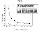
- FIG. 9 is a graph showing the relationship between spectrum linewidths before and after signal processing according to the present invention and spatial resolution.
- X-axis represents the spatial resolution in the unit of meter and Y-axis represents the linewidth in the unit of MHz.
- the linewidth with respect to spatial resolution of 1m before signal processing is increased approximately more than 50% compared to the linewidth with respect to spatial resolution of 10m.
- the linewidth is almost uniform after signal processing. This means that accuracy in the determination of the peak of the Brillouin gain spectrum is improved and thus accuracy in the measurement of a physical quantity is improved when signal processing for enhancing the spatial resolution according to the present invention is carried out.
- the length of the optical fiber 100 can be varied with the structure and size of a corresponding structure, a physical quantity to be measured and so on. Furthermore, while the strain is measured in the aforementioned embodiment of the present invention, a temperature caused by generation of heat can be also measured using the measuring method of the present invention.
- the normal spectrum is calculated by using a pair of pulse lights and comparing obtained gain spectra to each other.
- the Brillouin frequency is acquired based on the normal spectrum and thus a sensing signal can be obtained in a short optical fiber portion and spatial resolution can be remarkably enhanced.
Claims (14)
- Procédé de mesure d'une grandeur physique avec un capteur de Brillouin à fibre optique comprenant :- une étape (S1000) pour régler une fibre optique (100) sur une structure prédéterminée comme structure de capteur,- une étape (S2000) pour sélectionner une paire de première et de seconde impulsions lumineuses ayant des largeurs d'impulsion différentes,- une étape (S3000) pour transmettre séquentiellement la première et la seconde impulsion lumineuse par la fibre optique (100) pour obtenir un spectre de gain Brillouin,- une étape (S4000) pour comparer le spectre de gain Brillouin l'un avec l'autre pour obtenir un spectre normal,- une étape (S5000) pour déterminer une fréquence Brillouin ayant une valeur maximale à partir du spectre normal,
procédé caractérisé par- une étape (S6000) pour multiplier la fréquence Brillouin par un coefficient de conversion d'une grandeur physique à mesurer résultant d'une mesure de la grandeur physique, cette mesure fournissant en sortie un signal, et- le spectre normal s'obtient en appliquant l'équation suivante :
NBGS (x, ν) représente le spectre de gain Brillouin normalisé qui correspond à la lumière de dispersion arrière accumulée dans la partie correspondant à Δz2-Δz1, I(1) (x, ν) désignant le premier spectre de gain Brillouin, I(2) (x, ν) représentant le second spectre de gain Brillouin, x représentant la position du début de chaque lumière dispersée en retour, g (z', ν) représentant un coefficient de gain Brillouin, et ΔIpu (z', ν) désignant la densité de chaque impulsion lumineuse. - Procédé de mesure d'une grandeur physique selon la revendication 1,
caractérisé en ce que
la fibre optique (100) a un brin unique branché à partir d'une structure de couplage et revenant à la structure de couplage. - Procédé de mesure d'une grandeur physique selon la revendication 1,
caractérisé en ce que
les paramètres fondamentaux comprennent le nombre de fois en moyenne, le nombre d'échantillons, une plage de contrôle de fréquence et une largeur d'augmentation de fréquence progressive déterminée en avance pour un traitement de signal de la lumière renvoyée lors de la transmission des impulsions lumineuses. - Procédé de mesure d'une grandeur physique selon la revendication 3,
caractérisé en ce que
le nombre de fois en moyenne est égal à 200, la plage de contrôle de fréquence est comprise entre 10,79 MHz et 10,89 MHz, la largeur d'augmentation de fréquence progressive est de 1 MHz, la largeur d'impulsion de la première impulsion lumineuse est de 100 nsec, et la largeur d'impulsion de la seconde impulsion lumineuse est de 90 nsec. - Procédé de mesure d'une grandeur physique selon la revendication 1,
caractérisé en ce que
la largeur d'impulsion de la première impulsion lumineuse est plus grande que la largeur d'impulsion de la seconde impulsion lumineuse. - Procédé de mesure d'une grandeur physique selon la revendication 1,
caractérisé en ce que
l'étape (S3000) d'acquisition du spectre de gain Brillouin, comprend les étapes suivantes :- transmission de la première impulsion lumineuse ayant une grande largeur d'impulsion par la fibre optique (100) et transmission d'un échantillon lumineux correspondant pour obtenir le premier spectre de gain Brillouin (S3100), et- transmission de la seconde impulsion lumineuse ayant une largeur d'impulsion plus petite par la fibre optique (100) et transmission d'un échantillon lumineux correspondant pour obtenir le second spectre de gain Brillouin (S3200). - Procédé de mesure d'une grandeur physique selon la revendication 6,
caractérisé en ce que
l'étape (S3100) d'obtention du premier spectre de gain Brillouin comprend les étapes suivantes:- réglage de la fréquence de l'échantillon lumineux correspondant sur la fréquence initiale d'une plage de contrôle de fréquence prédéterminée (S3110),- transmission de la première impulsion lumineuse et du premier échantillon lumineux pour acquérir une première lumière de dispersion en retour(S3120),- acquisition répétée de la première lumière dispersée en retour par le nombre de fois en moyenne déterminé précédemment et formation de la moyenne des premières lumières dispersées en retour (S3130),- juger si l'acquisition répétée de la première lumière dispersée en retour par le nombre de fois en moyenne est terminée (S3140),- répéter les étapes entre l'étape (S3120) d'acquisition de la première lumière dispersée en retour si l'acquisition répétée de la première lumière dispersée en retour par le nombre de fois en moyenne est acquise et déterminer si la fréquence de l'échantillon lumineux correspondant à la fréquence finale de la plage de contrôle de fréquence lorsque l'acquisition répétée de la première lumière dispersée en retour par le nombre de fois en moyenne n'est pas terminée (S3150),- addition d'une fréquence correspondant à la largeur d'augmentation de la fréquence progressive déterminée précédemment par rapport à la fréquence de la lumière de l'échantillon et répétition des étapes d'acquisition de la première lumière de dispersion en retour lorsque la fréquence de l'échantillon lumineux ne correspond pas à la fréquence finale de la plage de contrôle de fréquence (S3160), et- application du premier spectre de gain Brillouin par rapport à la première lumière dispersée en retour si la fréquence de l'échantillon lumineux correspond à la fréquence finale de la plage de contrôle de fréquence (S3170). - Procédé de mesure d'une grandeur physique selon la revendication 7,
caractérisé en ce que
le premier spectre de gain Brillouin est représenté par l'équation suivante :
équation dans laquelle, Il (x, ν) représente l'intensité de la lumière de dispersion en retour correspondant à la première impulsion lumineuse qui correspond au premier spectre de gain Brillouin, x représente la position pour laquelle commence la lumière dispersée en retour, 1 (L, ν) représente l'intensité de la lumière dispersée en retour, L est la longueur de la fibre optique, α représente le coefficient de perte dans la fibre optique, g (z', ν) représente le coefficient de gain Brillouin, et ΔIpu (z', ν) représente l'intensité de l'impulsion lumineuse. - Procédé de mesure d'une grandeur physique selon la revendication 7,
caractérisé en ce que
le nombre de fois en moyenne est égal à 200, la plage de contrôle de fréquence est comprise entre 10,79 MHz et 10,89 MHz, la largeur d'augmentation progressive de fréquence est de 1 MHz et la largeur d'impulsion de la première impulsion lumineuse est égale à 100 nsec. - Procédé de mesure d'une grandeur physique selon la revendication 6,
caractérisé en ce que
l'étape (S3200) d'acquisition du second spectre de gain Brillouin comprend les étapes suivantes :- réglage de la fréquence de l'échantillon lumineux correspondant sur la fréquence initiale d'une plage de contrôle de fréquence prédéterminée (S3210),- transmission de la seconde impulsion lumineuse et de l'échantillon lumineux pour acquérir une seconde lumière dispersée en retour (S3220),- acquisition répétée de la seconde lumière dispersée en retour par le nombre de fois en moyenne prédéterminé et en faisant la moyenne de la seconde lumière dispersée en retour (S3230),- appréciation de savoir si l'acquisition répétée de la seconde lumière dispersée en retour par le nombre de fois en moyenne est terminée (S3240),- répétition des étapes (S3220) à partir de l'étape d'acquisition de la seconde lumière dispersée en retour si l'acquisition répétée de la seconde lumière dispersée en retour par le nombre de fois en moyenne est terminée, et- déterminer si la fréquence de l'échantillon lumineux correspond à la fréquence finale de la première plage de contrôle de fréquence si l'acquisition répétée de la seconde lumière dispersée en retour par le nombre de fois en moyenne n'est pas terminée (S3250),- addition d'une fréquence correspondant à la largeur d'augmentation de fréquence progressive, déterminée précédemment, à la fréquence de l'échantillon lumineux et répétition des étapes (S3220) à partir de l'étape d'acquisition de la seconde lumière dispersée en retour si la fréquence de l'échantillon lumineux ne correspond pas à la fréquence finale de la plage de contrôle de fréquence (S3260), et- application du second spectre de gain Brillouin par rapport à la seconde lumière répétée en retour si la fréquence de l'échantillon lumineux correspond à la fréquence finale de la plage de contrôle de fréquence (S3270). - Procédé de mesure d'une grandeur physique selon la revendication 10,
caractérisé en ce que
le second spectre de gain de Brillouin est représenté par l'équation suivante:
dans laquelle, I(2) (x, ν) désigne l'intensité de la lumière de dispersion en retour à partir de la seconde impulsion lumineuse, ce qui correspond au second spectre de gain Brillouin, x représente la position à laquelle démarre la lumière difractée en retour, 1 (L, ν) représente l'intensité de la lumière réfractée en retour, L est la longueur de la fibre optique, α désigne le coefficient de perte dans la fibre optique, g (z', ν) représente le coefficient de gain Brillouin, et ΔIpu (z', ν) désigne l'intensité de l'impulsion lumineuse. - Procédé de mesure d'une grandeur physique selon la revendication 10,
caractérisé en ce que
le nombre de fois en moyenne est égal à 200, la plage de contrôle de fréquence est comprise entre 10,79 MHz et 10,89 MHz, la largeur d'augmentation progressive de fréquence est égale à 1 MHz et la largeur d'impulsion de la seconde impulsion lumineuse est égale à 90 nsec. - Procédé de mesure d'une grandeur physique selon la revendication 1,
caractérisé en ce que
la structure est un simple faisceau creux 200 d'une longueur approximative de 8 m et les deux extrémités du faisceau 200 sont portées et la section principale du faisceau a une forme carrée. - Procédé de mesure d'une grandeur physique selon la revendication 13,
caractérisé en ce que
la contrainte est détectée principalement dans une portion approximativement comprise entre 2,44 km et 2,5 km lorsque la fibre optique (100) d'une longueur approximative de 4 km est appliquée à la surface du faisceau (200) et une charge pondérale concentrée (300) d'approximativement 200 g est appliquée au faisceau (200).
Applications Claiming Priority (2)
| Application Number | Priority Date | Filing Date | Title |
|---|---|---|---|
| KR1020040012757A KR100625807B1 (ko) | 2004-02-25 | 2004-02-25 | 브릴루앙 광섬유 센서를 이용하는 물리량 측정방법 |
| KR2004012757 | 2004-02-25 |
Publications (3)
| Publication Number | Publication Date |
|---|---|
| EP1568981A2 EP1568981A2 (fr) | 2005-08-31 |
| EP1568981A3 EP1568981A3 (fr) | 2008-10-22 |
| EP1568981B1 true EP1568981B1 (fr) | 2010-07-14 |
Family
ID=34747948
Family Applications (1)
| Application Number | Title | Priority Date | Filing Date |
|---|---|---|---|
| EP05003611A Not-in-force EP1568981B1 (fr) | 2004-02-25 | 2005-02-19 | Procédé de mesure d'une quantité physique employant un capteur de Brillouin à fibre optique. |
Country Status (7)
| Country | Link |
|---|---|
| US (1) | US7227123B2 (fr) |
| EP (1) | EP1568981B1 (fr) |
| JP (1) | JP4260120B2 (fr) |
| KR (1) | KR100625807B1 (fr) |
| CN (1) | CN1332180C (fr) |
| AT (1) | ATE474216T1 (fr) |
| DE (1) | DE602005022244D1 (fr) |
Cited By (1)
| Publication number | Priority date | Publication date | Assignee | Title |
|---|---|---|---|---|
| CN111051832A (zh) * | 2017-05-11 | 2020-04-21 | 费布斯光学公司 | 用于光纤分布式测量的光电装置 |
Families Citing this family (21)
| Publication number | Priority date | Publication date | Assignee | Title |
|---|---|---|---|---|
| US7473906B2 (en) | 2005-04-28 | 2009-01-06 | Claudio Oliveira Egalon | Reversible, low cost, distributed optical fiber sensor with high spatial resolution |
| JP4775094B2 (ja) * | 2006-04-21 | 2011-09-21 | 住友電気工業株式会社 | ブリルアンスペクトル測定装置 |
| US7356207B2 (en) | 2006-06-05 | 2008-04-08 | Honeywell International, Inc. | Method and system for adjusting the sensitivity of optical sensors |
| JP4775173B2 (ja) * | 2006-08-24 | 2011-09-21 | 住友電気工業株式会社 | 光ファイバ温度センサ |
| JP5122120B2 (ja) * | 2006-12-13 | 2013-01-16 | 横河電機株式会社 | 光ファイバ特性測定装置 |
| JP4643551B2 (ja) * | 2006-12-20 | 2011-03-02 | 富士通株式会社 | 周波数自動監視回路、電子装置、周波数自動監視方法および周波数自動監視プログラム |
| US8287184B2 (en) * | 2006-12-28 | 2012-10-16 | Sumitomo Electric Industries, Ltd. | Fluid physical quantity measuring method and control method |
| JP5070874B2 (ja) * | 2007-02-14 | 2012-11-14 | 住友電気工業株式会社 | 測定装置、異常検知装置及び異常検知方法 |
| JP4930107B2 (ja) * | 2007-03-06 | 2012-05-16 | 住友電気工業株式会社 | 光ファイバのpmd特性測定方法、線引方法、異常個所特定方法、光ファイバ伝送路構築方法 |
| US7526149B1 (en) * | 2008-07-21 | 2009-04-28 | Qorex, Llc | Dual wavelength strain-temperature Brillouin sensing system and method |
| CN101397904B (zh) * | 2008-11-05 | 2012-08-29 | 大庆油田有限责任公司 | 一种应用光纤传感器监测井下套管受力的方法 |
| US8463083B2 (en) * | 2009-01-30 | 2013-06-11 | Claudio Oliveira Egalon | Side illuminated multi point multi parameter optical fiber sensor |
| GB201019117D0 (en) | 2010-11-11 | 2010-12-29 | Fotech Solutions Ltd | Distributed optical fibre sensor |
| ITGE20110007A1 (it) * | 2011-01-26 | 2012-07-27 | Pegaso Systems S R L | Sistema di monitoraggio termico e/o di trasmissione informazione per navi. |
| ES2392527B1 (es) | 2011-05-13 | 2013-11-11 | Universidad Pública de Navarra | Dispositivo y procedimiento para la medida de la distribución de magnitudes físicas en una fibra óptica |
| US20130008180A1 (en) * | 2011-07-07 | 2013-01-10 | Diatzikis Evangelos V | Method and apparatus for distributed cleft and liberated tile detection achieving full coverage of the turbine combustion chamber |
| CN103791935B (zh) * | 2014-01-14 | 2016-10-05 | 燕山大学 | 一种脉冲细分叠加信号处理方法 |
| US9341543B2 (en) | 2014-10-16 | 2016-05-17 | Texas Instruments Incorporated | Method and OTDR apparatus for optical cable defect location with reduced memory requirement |
| EP3511155A1 (fr) | 2018-01-12 | 2019-07-17 | Technische Universität Graz | Machine et procédé de fabrication d'additif |
| CN111750912B (zh) * | 2020-06-23 | 2022-07-15 | 武汉烽理光电技术有限公司 | 高空间分辨率的大容量光栅阵列otdr差分解调方法及系统 |
| CN111896137B (zh) * | 2020-06-29 | 2022-02-18 | 太原理工大学 | 一种厘米级空间分辨率的分布式光纤拉曼传感装置及方法 |
Family Cites Families (16)
| Publication number | Priority date | Publication date | Assignee | Title |
|---|---|---|---|---|
| GB8520827D0 (en) * | 1985-08-20 | 1985-09-25 | York Ventures & Special Optica | Fibre-optic sensing devices |
| DE377549T1 (de) * | 1989-01-03 | 1990-11-08 | Marcos Y. Southbridge Mass. Us Kleinerman | Fernmessung physikalischer variablen mit faseroptischen systemen. |
| GB9315231D0 (en) * | 1993-07-22 | 1993-09-08 | York Ltd | Optical time domain reflextometry |
| GB9408502D0 (en) * | 1994-04-28 | 1994-06-22 | Furukawa Research & Engineerin | Distributed sensing apparatus |
| JP3094925B2 (ja) * | 1996-10-31 | 2000-10-03 | 安藤電気株式会社 | 光ファイバ歪測定装置 |
| GB9626099D0 (en) * | 1996-12-16 | 1997-02-05 | King S College London | Distributed strain and temperature measuring system |
| US5929990A (en) * | 1997-03-19 | 1999-07-27 | Litton Systems, Inc. | Fabry-perot pressure sensing system with ratioed quadrature pulse detection |
| GB9720980D0 (en) * | 1997-10-02 | 1997-12-03 | Furukawa Research & Engineerin | Distributed sensing apparatus |
| JP3524431B2 (ja) * | 1998-06-19 | 2004-05-10 | 岸田 欣増 | 測定装置 |
| GB2367890B (en) * | 2000-10-06 | 2004-06-23 | Abb Offshore Systems Ltd | Sensing strain in hydrocarbon wells |
| JP3686588B2 (ja) * | 2001-02-26 | 2005-08-24 | 日本電信電話株式会社 | 光ファイバひずみ計測方法及びその装置 |
| JP3795779B2 (ja) * | 2001-08-24 | 2006-07-12 | 日本電信電話株式会社 | 光ファイバセンサによる構造部材応力集中部位検出方法 |
| KR100468612B1 (ko) * | 2001-09-28 | 2005-01-27 | 주식회사 세기엔지니어링 | 광섬유 브릴루앙 시간영역해석 센서시스템과 이를 이용한변형률 측정 방법 |
| TW500912B (en) * | 2001-11-30 | 2002-09-01 | Nat Chao Tung University Libra | Method to sense the stress and temperature distribution of fiber simultaneously |
| US6813403B2 (en) * | 2002-03-14 | 2004-11-02 | Fiber Optic Systems Technology, Inc. | Monitoring of large structures using brillouin spectrum analysis |
| AU2002344444A1 (en) * | 2002-11-01 | 2004-05-25 | Kinzo Kishida | Distributed optical fiber sensor system |
-
2004
- 2004-02-25 KR KR1020040012757A patent/KR100625807B1/ko not_active IP Right Cessation
-
2005
- 2005-02-19 AT AT05003611T patent/ATE474216T1/de not_active IP Right Cessation
- 2005-02-19 EP EP05003611A patent/EP1568981B1/fr not_active Not-in-force
- 2005-02-19 DE DE602005022244T patent/DE602005022244D1/de active Active
- 2005-02-22 US US11/062,714 patent/US7227123B2/en active Active - Reinstated
- 2005-02-23 JP JP2005047373A patent/JP4260120B2/ja not_active Expired - Fee Related
- 2005-02-24 CN CNB2005100088672A patent/CN1332180C/zh not_active Expired - Fee Related
Cited By (1)
| Publication number | Priority date | Publication date | Assignee | Title |
|---|---|---|---|---|
| CN111051832A (zh) * | 2017-05-11 | 2020-04-21 | 费布斯光学公司 | 用于光纤分布式测量的光电装置 |
Also Published As
| Publication number | Publication date |
|---|---|
| EP1568981A3 (fr) | 2008-10-22 |
| KR100625807B1 (ko) | 2006-09-20 |
| US7227123B2 (en) | 2007-06-05 |
| EP1568981A2 (fr) | 2005-08-31 |
| JP4260120B2 (ja) | 2009-04-30 |
| CN1332180C (zh) | 2007-08-15 |
| KR20050087136A (ko) | 2005-08-31 |
| ATE474216T1 (de) | 2010-07-15 |
| CN1661333A (zh) | 2005-08-31 |
| JP2005241643A (ja) | 2005-09-08 |
| DE602005022244D1 (de) | 2010-08-26 |
| US20050207752A1 (en) | 2005-09-22 |
Similar Documents
| Publication | Publication Date | Title |
|---|---|---|
| EP1568981B1 (fr) | Procédé de mesure d'une quantité physique employant un capteur de Brillouin à fibre optique. | |
| US7284903B2 (en) | Distributed optical fibre measurements | |
| CA2652901C (fr) | Marqueur d'emplacement pour systemes de detection distribuee de temperature | |
| US7020360B2 (en) | Wavelength dispersion probing system | |
| US7534031B2 (en) | Temperature measuring device and temperature measurement method | |
| US6237421B1 (en) | Apparatus for measuring a characteristic of an object using an optical fiber and light pulses | |
| JP2007535674A (ja) | 分布型の光学的検知システムにおけるブリルアン周波数の直接測定 | |
| JPH0650846A (ja) | 光ファイバーの有効屈折率測定装置 | |
| US20040208413A1 (en) | Cryogenic optical fibre temperature sensor | |
| US11092513B1 (en) | OTDR calibration method using multiple levels of internal optical fiber backscatter | |
| JP3935631B2 (ja) | 光ファイバ歪計測装置及び方法 | |
| JP2769185B2 (ja) | 後方散乱光測定装置 | |
| US7312435B2 (en) | Determination of a physical state of an optical device | |
| JP3686588B2 (ja) | 光ファイバひずみ計測方法及びその装置 | |
| JP3502329B2 (ja) | 光ファイバひずみ計測方法およびその装置 | |
| JP3795779B2 (ja) | 光ファイバセンサによる構造部材応力集中部位検出方法 | |
| JP3493158B2 (ja) | 光ファイバひずみ計測方法及びその方法を実現するための記録媒体 | |
| JP3439104B2 (ja) | 歪み評価装置 | |
| US20220326005A1 (en) | Distributed Vibration Measuring Device and Method | |
| JP2003075132A (ja) | 光学的歪み測定方法およびその装置 | |
| KR20050062796A (ko) | 구조물의 처짐 측정 방법 | |
| GB2333357A (en) | Fibre optic temperature sensor | |
| KR100523939B1 (ko) | 광커넥터 및 광섬유를 이용한 물리량 측정장치 | |
| JPH10160633A (ja) | 単一モード光ファイバの特性評価方法 | |
| JPH11101711A (ja) | 擬似otdr測定波形生成方法 |
Legal Events
| Date | Code | Title | Description |
|---|---|---|---|
| PUAI | Public reference made under article 153(3) epc to a published international application that has entered the european phase |
Free format text: ORIGINAL CODE: 0009012 |
|
| AK | Designated contracting states |
Kind code of ref document: A2 Designated state(s): AT BE BG CH CY CZ DE DK EE ES FI FR GB GR HU IE IS IT LI LT LU MC NL PL PT RO SE SI SK TR |
|
| AX | Request for extension of the european patent |
Extension state: AL BA HR LV MK YU |
|
| PUAL | Search report despatched |
Free format text: ORIGINAL CODE: 0009013 |
|
| AK | Designated contracting states |
Kind code of ref document: A3 Designated state(s): AT BE BG CH CY CZ DE DK EE ES FI FR GB GR HU IE IS IT LI LT LU MC NL PL PT RO SE SI SK TR |
|
| AX | Request for extension of the european patent |
Extension state: AL BA HR LV MK YU |
|
| RIC1 | Information provided on ipc code assigned before grant |
Ipc: G01B 11/16 20060101ALI20080918BHEP Ipc: G01D 5/353 20060101ALI20080918BHEP Ipc: G01K 11/32 20060101ALI20080918BHEP Ipc: G01L 1/24 20060101AFI20050630BHEP |
|
| 17P | Request for examination filed |
Effective date: 20081121 |
|
| 17Q | First examination report despatched |
Effective date: 20081216 |
|
| AKX | Designation fees paid |
Designated state(s): AT BE BG CH CY CZ DE DK EE ES FI FR GB GR HU IE IS IT LI LT LU MC NL PL PT RO SE SI SK TR |
|
| GRAP | Despatch of communication of intention to grant a patent |
Free format text: ORIGINAL CODE: EPIDOSNIGR1 |
|
| RTI1 | Title (correction) |
Free format text: PHYSICAL QUANTITY MEASURING METHOD USING BRILLOUIN OPTICAL FIBER SENSOR |
|
| GRAS | Grant fee paid |
Free format text: ORIGINAL CODE: EPIDOSNIGR3 |
|
| GRAA | (expected) grant |
Free format text: ORIGINAL CODE: 0009210 |
|
| AK | Designated contracting states |
Kind code of ref document: B1 Designated state(s): AT BE BG CH CY CZ DE DK EE ES FI FR GB GR HU IE IS IT LI LT LU MC NL PL PT RO SE SI SK TR |
|
| REG | Reference to a national code |
Ref country code: GB Ref legal event code: FG4D |
|
| REG | Reference to a national code |
Ref country code: CH Ref legal event code: EP |
|
| REG | Reference to a national code |
Ref country code: IE Ref legal event code: FG4D |
|
| REF | Corresponds to: |
Ref document number: 602005022244 Country of ref document: DE Date of ref document: 20100826 Kind code of ref document: P |
|
| REG | Reference to a national code |
Ref country code: CH Ref legal event code: NV Representative=s name: SCHMAUDER & PARTNER AG PATENTANWALTSBUERO |
|
| REG | Reference to a national code |
Ref country code: NL Ref legal event code: VDEP Effective date: 20100714 |
|
| LTIE | Lt: invalidation of european patent or patent extension |
Effective date: 20100714 |
|
| PG25 | Lapsed in a contracting state [announced via postgrant information from national office to epo] |
Ref country code: NL Free format text: LAPSE BECAUSE OF FAILURE TO SUBMIT A TRANSLATION OF THE DESCRIPTION OR TO PAY THE FEE WITHIN THE PRESCRIBED TIME-LIMIT Effective date: 20100714 Ref country code: AT Free format text: LAPSE BECAUSE OF FAILURE TO SUBMIT A TRANSLATION OF THE DESCRIPTION OR TO PAY THE FEE WITHIN THE PRESCRIBED TIME-LIMIT Effective date: 20100714 Ref country code: LT Free format text: LAPSE BECAUSE OF FAILURE TO SUBMIT A TRANSLATION OF THE DESCRIPTION OR TO PAY THE FEE WITHIN THE PRESCRIBED TIME-LIMIT Effective date: 20100714 Ref country code: FI Free format text: LAPSE BECAUSE OF FAILURE TO SUBMIT A TRANSLATION OF THE DESCRIPTION OR TO PAY THE FEE WITHIN THE PRESCRIBED TIME-LIMIT Effective date: 20100714 |
|
| PG25 | Lapsed in a contracting state [announced via postgrant information from national office to epo] |
Ref country code: PL Free format text: LAPSE BECAUSE OF FAILURE TO SUBMIT A TRANSLATION OF THE DESCRIPTION OR TO PAY THE FEE WITHIN THE PRESCRIBED TIME-LIMIT Effective date: 20100714 Ref country code: BG Free format text: LAPSE BECAUSE OF FAILURE TO SUBMIT A TRANSLATION OF THE DESCRIPTION OR TO PAY THE FEE WITHIN THE PRESCRIBED TIME-LIMIT Effective date: 20101014 Ref country code: CY Free format text: LAPSE BECAUSE OF FAILURE TO SUBMIT A TRANSLATION OF THE DESCRIPTION OR TO PAY THE FEE WITHIN THE PRESCRIBED TIME-LIMIT Effective date: 20100714 Ref country code: IS Free format text: LAPSE BECAUSE OF FAILURE TO SUBMIT A TRANSLATION OF THE DESCRIPTION OR TO PAY THE FEE WITHIN THE PRESCRIBED TIME-LIMIT Effective date: 20101114 Ref country code: PT Free format text: LAPSE BECAUSE OF FAILURE TO SUBMIT A TRANSLATION OF THE DESCRIPTION OR TO PAY THE FEE WITHIN THE PRESCRIBED TIME-LIMIT Effective date: 20101115 Ref country code: SI Free format text: LAPSE BECAUSE OF FAILURE TO SUBMIT A TRANSLATION OF THE DESCRIPTION OR TO PAY THE FEE WITHIN THE PRESCRIBED TIME-LIMIT Effective date: 20100714 |
|
| PG25 | Lapsed in a contracting state [announced via postgrant information from national office to epo] |
Ref country code: SE Free format text: LAPSE BECAUSE OF FAILURE TO SUBMIT A TRANSLATION OF THE DESCRIPTION OR TO PAY THE FEE WITHIN THE PRESCRIBED TIME-LIMIT Effective date: 20100714 Ref country code: GR Free format text: LAPSE BECAUSE OF FAILURE TO SUBMIT A TRANSLATION OF THE DESCRIPTION OR TO PAY THE FEE WITHIN THE PRESCRIBED TIME-LIMIT Effective date: 20101015 Ref country code: BE Free format text: LAPSE BECAUSE OF FAILURE TO SUBMIT A TRANSLATION OF THE DESCRIPTION OR TO PAY THE FEE WITHIN THE PRESCRIBED TIME-LIMIT Effective date: 20100714 |
|
| PG25 | Lapsed in a contracting state [announced via postgrant information from national office to epo] |
Ref country code: DK Free format text: LAPSE BECAUSE OF FAILURE TO SUBMIT A TRANSLATION OF THE DESCRIPTION OR TO PAY THE FEE WITHIN THE PRESCRIBED TIME-LIMIT Effective date: 20100714 |
|
| PLBE | No opposition filed within time limit |
Free format text: ORIGINAL CODE: 0009261 |
|
| STAA | Information on the status of an ep patent application or granted ep patent |
Free format text: STATUS: NO OPPOSITION FILED WITHIN TIME LIMIT |
|
| PG25 | Lapsed in a contracting state [announced via postgrant information from national office to epo] |
Ref country code: CZ Free format text: LAPSE BECAUSE OF FAILURE TO SUBMIT A TRANSLATION OF THE DESCRIPTION OR TO PAY THE FEE WITHIN THE PRESCRIBED TIME-LIMIT Effective date: 20100714 Ref country code: EE Free format text: LAPSE BECAUSE OF FAILURE TO SUBMIT A TRANSLATION OF THE DESCRIPTION OR TO PAY THE FEE WITHIN THE PRESCRIBED TIME-LIMIT Effective date: 20100714 Ref country code: RO Free format text: LAPSE BECAUSE OF FAILURE TO SUBMIT A TRANSLATION OF THE DESCRIPTION OR TO PAY THE FEE WITHIN THE PRESCRIBED TIME-LIMIT Effective date: 20100714 Ref country code: SK Free format text: LAPSE BECAUSE OF FAILURE TO SUBMIT A TRANSLATION OF THE DESCRIPTION OR TO PAY THE FEE WITHIN THE PRESCRIBED TIME-LIMIT Effective date: 20100714 Ref country code: IT Free format text: LAPSE BECAUSE OF FAILURE TO SUBMIT A TRANSLATION OF THE DESCRIPTION OR TO PAY THE FEE WITHIN THE PRESCRIBED TIME-LIMIT Effective date: 20100714 |
|
| 26N | No opposition filed |
Effective date: 20110415 |
|
| PG25 | Lapsed in a contracting state [announced via postgrant information from national office to epo] |
Ref country code: ES Free format text: LAPSE BECAUSE OF FAILURE TO SUBMIT A TRANSLATION OF THE DESCRIPTION OR TO PAY THE FEE WITHIN THE PRESCRIBED TIME-LIMIT Effective date: 20101025 |
|
| REG | Reference to a national code |
Ref country code: DE Ref legal event code: R097 Ref document number: 602005022244 Country of ref document: DE Effective date: 20110415 |
|
| PG25 | Lapsed in a contracting state [announced via postgrant information from national office to epo] |
Ref country code: MC Free format text: LAPSE BECAUSE OF NON-PAYMENT OF DUE FEES Effective date: 20110228 |
|
| REG | Reference to a national code |
Ref country code: IE Ref legal event code: MM4A |
|
| PG25 | Lapsed in a contracting state [announced via postgrant information from national office to epo] |
Ref country code: IE Free format text: LAPSE BECAUSE OF NON-PAYMENT OF DUE FEES Effective date: 20110219 |
|
| PG25 | Lapsed in a contracting state [announced via postgrant information from national office to epo] |
Ref country code: LU Free format text: LAPSE BECAUSE OF NON-PAYMENT OF DUE FEES Effective date: 20110219 |
|
| PG25 | Lapsed in a contracting state [announced via postgrant information from national office to epo] |
Ref country code: TR Free format text: LAPSE BECAUSE OF FAILURE TO SUBMIT A TRANSLATION OF THE DESCRIPTION OR TO PAY THE FEE WITHIN THE PRESCRIBED TIME-LIMIT Effective date: 20100714 |
|
| PG25 | Lapsed in a contracting state [announced via postgrant information from national office to epo] |
Ref country code: HU Free format text: LAPSE BECAUSE OF FAILURE TO SUBMIT A TRANSLATION OF THE DESCRIPTION OR TO PAY THE FEE WITHIN THE PRESCRIBED TIME-LIMIT Effective date: 20100714 |
|
| REG | Reference to a national code |
Ref country code: DE Ref legal event code: R082 Ref document number: 602005022244 Country of ref document: DE Representative=s name: PATENTANWAELTE WEICKMANN & WEICKMANN, DE Ref country code: DE Ref legal event code: R082 Ref document number: 602005022244 Country of ref document: DE Representative=s name: WEICKMANN & WEICKMANN PATENTANWAELTE - RECHTSA, DE Ref country code: DE Ref legal event code: R082 Ref document number: 602005022244 Country of ref document: DE Representative=s name: WEICKMANN & WEICKMANN PATENT- UND RECHTSANWAEL, DE |
|
| REG | Reference to a national code |
Ref country code: FR Ref legal event code: PLFP Year of fee payment: 12 |
|
| REG | Reference to a national code |
Ref country code: FR Ref legal event code: PLFP Year of fee payment: 13 |
|
| PGFP | Annual fee paid to national office [announced via postgrant information from national office to epo] |
Ref country code: DE Payment date: 20170104 Year of fee payment: 13 Ref country code: FR Payment date: 20170106 Year of fee payment: 13 Ref country code: CH Payment date: 20170105 Year of fee payment: 13 |
|
| PGFP | Annual fee paid to national office [announced via postgrant information from national office to epo] |
Ref country code: GB Payment date: 20170105 Year of fee payment: 13 |
|
| REG | Reference to a national code |
Ref country code: DE Ref legal event code: R119 Ref document number: 602005022244 Country of ref document: DE |
|
| REG | Reference to a national code |
Ref country code: CH Ref legal event code: PL |
|
| GBPC | Gb: european patent ceased through non-payment of renewal fee |
Effective date: 20180219 |
|
| PG25 | Lapsed in a contracting state [announced via postgrant information from national office to epo] |
Ref country code: LI Free format text: LAPSE BECAUSE OF NON-PAYMENT OF DUE FEES Effective date: 20180228 Ref country code: CH Free format text: LAPSE BECAUSE OF NON-PAYMENT OF DUE FEES Effective date: 20180228 |
|
| REG | Reference to a national code |
Ref country code: FR Ref legal event code: ST Effective date: 20181031 |
|
| PG25 | Lapsed in a contracting state [announced via postgrant information from national office to epo] |
Ref country code: DE Free format text: LAPSE BECAUSE OF NON-PAYMENT OF DUE FEES Effective date: 20180901 |
|
| PG25 | Lapsed in a contracting state [announced via postgrant information from national office to epo] |
Ref country code: GB Free format text: LAPSE BECAUSE OF NON-PAYMENT OF DUE FEES Effective date: 20180219 Ref country code: FR Free format text: LAPSE BECAUSE OF NON-PAYMENT OF DUE FEES Effective date: 20180228 |