EP1568894B1 - Vérin à actionnement par fluide - Google Patents
Vérin à actionnement par fluide Download PDFInfo
- Publication number
- EP1568894B1 EP1568894B1 EP05000205A EP05000205A EP1568894B1 EP 1568894 B1 EP1568894 B1 EP 1568894B1 EP 05000205 A EP05000205 A EP 05000205A EP 05000205 A EP05000205 A EP 05000205A EP 1568894 B1 EP1568894 B1 EP 1568894B1
- Authority
- EP
- European Patent Office
- Prior art keywords
- operating cylinder
- cylinder according
- cover
- position sensor
- sensor
- Prior art date
- Legal status (The legal status is an assumption and is not a legal conclusion. Google has not performed a legal analysis and makes no representation as to the accuracy of the status listed.)
- Expired - Lifetime
Links
- 239000012530 fluid Substances 0.000 title description 8
- 238000001514 detection method Methods 0.000 claims description 10
- 239000000463 material Substances 0.000 claims description 8
- 239000004033 plastic Substances 0.000 claims description 7
- 229920003023 plastic Polymers 0.000 claims description 7
- 238000004873 anchoring Methods 0.000 claims description 6
- 235000014676 Phragmites communis Nutrition 0.000 claims description 3
- 238000007598 dipping method Methods 0.000 claims 1
- 230000033001 locomotion Effects 0.000 description 5
- 238000007789 sealing Methods 0.000 description 5
- 238000004519 manufacturing process Methods 0.000 description 4
- 238000003466 welding Methods 0.000 description 4
- 238000010276 construction Methods 0.000 description 3
- 208000000260 Warts Diseases 0.000 description 2
- 230000001771 impaired effect Effects 0.000 description 2
- 238000009434 installation Methods 0.000 description 2
- 238000007493 shaping process Methods 0.000 description 2
- 201000010153 skin papilloma Diseases 0.000 description 2
- 230000007704 transition Effects 0.000 description 2
- 229920002430 Fibre-reinforced plastic Polymers 0.000 description 1
- 230000005540 biological transmission Effects 0.000 description 1
- 238000013016 damping Methods 0.000 description 1
- 230000001419 dependent effect Effects 0.000 description 1
- 238000011161 development Methods 0.000 description 1
- 230000018109 developmental process Effects 0.000 description 1
- 238000006073 displacement reaction Methods 0.000 description 1
- 238000005516 engineering process Methods 0.000 description 1
- 238000011156 evaluation Methods 0.000 description 1
- 239000011151 fibre-reinforced plastic Substances 0.000 description 1
- 238000003780 insertion Methods 0.000 description 1
- 230000037431 insertion Effects 0.000 description 1
- 230000003993 interaction Effects 0.000 description 1
- 239000002184 metal Substances 0.000 description 1
- 230000000284 resting effect Effects 0.000 description 1
Images


Classifications
-
- F—MECHANICAL ENGINEERING; LIGHTING; HEATING; WEAPONS; BLASTING
- F15—FLUID-PRESSURE ACTUATORS; HYDRAULICS OR PNEUMATICS IN GENERAL
- F15B—SYSTEMS ACTING BY MEANS OF FLUIDS IN GENERAL; FLUID-PRESSURE ACTUATORS, e.g. SERVOMOTORS; DETAILS OF FLUID-PRESSURE SYSTEMS, NOT OTHERWISE PROVIDED FOR
- F15B15/00—Fluid-actuated devices for displacing a member from one position to another; Gearing associated therewith
- F15B15/20—Other details, e.g. assembly with regulating devices
- F15B15/28—Means for indicating the position, e.g. end of stroke
- F15B15/2807—Position switches, i.e. means for sensing of discrete positions only, e.g. limit switches
-
- F—MECHANICAL ENGINEERING; LIGHTING; HEATING; WEAPONS; BLASTING
- F15—FLUID-PRESSURE ACTUATORS; HYDRAULICS OR PNEUMATICS IN GENERAL
- F15B—SYSTEMS ACTING BY MEANS OF FLUIDS IN GENERAL; FLUID-PRESSURE ACTUATORS, e.g. SERVOMOTORS; DETAILS OF FLUID-PRESSURE SYSTEMS, NOT OTHERWISE PROVIDED FOR
- F15B15/00—Fluid-actuated devices for displacing a member from one position to another; Gearing associated therewith
- F15B15/08—Characterised by the construction of the motor unit
- F15B15/14—Characterised by the construction of the motor unit of the straight-cylinder type
- F15B15/1423—Component parts; Constructional details
- F15B15/1433—End caps
-
- F—MECHANICAL ENGINEERING; LIGHTING; HEATING; WEAPONS; BLASTING
- F15—FLUID-PRESSURE ACTUATORS; HYDRAULICS OR PNEUMATICS IN GENERAL
- F15B—SYSTEMS ACTING BY MEANS OF FLUIDS IN GENERAL; FLUID-PRESSURE ACTUATORS, e.g. SERVOMOTORS; DETAILS OF FLUID-PRESSURE SYSTEMS, NOT OTHERWISE PROVIDED FOR
- F15B15/00—Fluid-actuated devices for displacing a member from one position to another; Gearing associated therewith
- F15B15/08—Characterised by the construction of the motor unit
- F15B15/14—Characterised by the construction of the motor unit of the straight-cylinder type
- F15B15/1423—Component parts; Constructional details
- F15B15/1438—Cylinder to end cap assemblies
-
- F—MECHANICAL ENGINEERING; LIGHTING; HEATING; WEAPONS; BLASTING
- F15—FLUID-PRESSURE ACTUATORS; HYDRAULICS OR PNEUMATICS IN GENERAL
- F15B—SYSTEMS ACTING BY MEANS OF FLUIDS IN GENERAL; FLUID-PRESSURE ACTUATORS, e.g. SERVOMOTORS; DETAILS OF FLUID-PRESSURE SYSTEMS, NOT OTHERWISE PROVIDED FOR
- F15B15/00—Fluid-actuated devices for displacing a member from one position to another; Gearing associated therewith
- F15B15/20—Other details, e.g. assembly with regulating devices
- F15B15/28—Means for indicating the position, e.g. end of stroke
- F15B15/2892—Means for indicating the position, e.g. end of stroke characterised by the attachment means
-
- F—MECHANICAL ENGINEERING; LIGHTING; HEATING; WEAPONS; BLASTING
- F15—FLUID-PRESSURE ACTUATORS; HYDRAULICS OR PNEUMATICS IN GENERAL
- F15B—SYSTEMS ACTING BY MEANS OF FLUIDS IN GENERAL; FLUID-PRESSURE ACTUATORS, e.g. SERVOMOTORS; DETAILS OF FLUID-PRESSURE SYSTEMS, NOT OTHERWISE PROVIDED FOR
- F15B2215/00—Fluid-actuated devices for displacing a member from one position to another
- F15B2215/30—Constructional details thereof
- F15B2215/305—Constructional details thereof characterised by the use of special materials
Definitions
- the invention relates to a fluid-actuated working cylinder, the cylinder housing having a cylinder tube which is inserted with at least one of its two end portions in a cover, so that it is overlapped on the outer circumference of an annular cover extension coaxial, in which the piston of the working cylinder when reaching its end position can, and with at least one outside of the cylinder housing arranged sensor receptacle, which is provided for fixing a the end position detection of the piston serving position sensor.
- the cylinder housing In a fluid-actuated working cylinder of this type known from EP 0 572 774 B1, the cylinder housing consists of two end covers and one end plugged into the end cover, with these by a locking connection or a welded connection firmly connected cylinder tube.
- the cylinder tube is overlapped by an annular cover extension of the respective end cover outside.
- the piston of the working cylinder moves to the end position, it dips more or less into the cover extension.
- the cylinder tube is provided on the outer circumference with a groove-like sensor receptacle in which a position sensor can be fixed.
- the sensor receptacle may extend over the entire length of the cylinder tube or only in the region between the axially oriented End faces of the cover extensions of the two end covers. Regardless of the length of the sensor holder, the sensor can always be installed only in the area between the two cover extensions, which only allows an exact Endlagenabfrage if the cover extensions are relatively short, so that the piston dips only a short distance.
- this has the disadvantage that the axial overlap of the cover extension and cylinder tube is relatively low and thereby the stability of the connection can be impaired.
- FR-A-2 079 871 discloses a positioning device for working cylinders, wherein the cylinder housing is inserted in a cover and a cover extension of the cylinder housing carries a positioner.
- the positioner works via a torsion bar with the piston rod of the working cylinder and controls the fluid loading of the working cylinder in dependence on the piston position and the resulting rotational position of the torsion bar.
- the sensor receptacle is arranged on the outer circumference of the cover extension, that it is traversed by the piston immersed in the cover extension, wherein it is formed by a linear extension having a channel into which the position sensor can be inserted or used ,
- the attachment measures for the position sensor can be limited to the end cap.
- On the cylinder tube itself can be dispensed with appropriate fastening measures, which allows independent of the desired length cost-effective production of the cylinder tube with a simple geometry.
- the sensor receptacle is located on the outer circumference of the cover extension, the piston to be detected reaches in the end position in the immediate vicinity the position sensor fixed in the sensor holder, which allows a precise position detection.
- the cover extension can be achieved by correspondingly large axial dimensions of the cover extension a very stable connection between the end cap and the inserted into this cylinder tube.
- the overall length of the cover extension can be optimally utilized for the realization of the sensor receptacle.
- the sensor receptacle extends over the entire length of the cover extension.
- the sensor receptacle can protrude beyond the cover extension on the rear side and extend at least a little along the main part of the end cover adjoining the cover extension.
- the realization of a relatively long sensor receptacle is of particular advantage, because it allows, if necessary, to fix the position sensor in different longitudinal positions therein, without this frontally protrudes so that its stability would be impaired. If the position sensor is completely accommodated within the sensor receptacle, not only the stable attachment but also good protection against damaging external influences can be achieved.
- the piston can not be detected immediately, it is expediently with a suitable actuating element equipped, which is able to activate the position sensor fixed in the sensor holder.
- the actuating element is preferably a permanent magnet. This can for example be a coaxially arranged on the piston ring magnet.
- the sensor used for position detection is, for example, a Hall sensor or a reed switch.
- both the cylinder tube and the end cover completely or partially made of plastic material, the two components can be very easily connected in the context of a gas-tight weld without additional use of sealing elements together.
- a friction welding connection or an ultrasonic welding connection is used.
- the channel facing away from the cover extension, with respect to the longitudinal axis of the cylinder housing radially outer side may be covered by an integrally formed with the end cover wall, which is divided in the longitudinal direction into a plurality of transversely elastically deformable wall sections.
- the wall sections are provided with first latching means, for example in the form of wart-like projections.
- first latching means for example in the form of wart-like projections.
- second locking means for example, realized in the form of a recess - can engage releasably.
- the position sensor can be fixed in stages in different longitudinal positions in the sensor holder.
- the channel forming the sensor receptacle can also be designed as a longitudinal groove which is open on the outside and which has a narrower groove neck and a wider anchoring section adjoining it in the groove depth direction.
- the position sensor can be fixed in this anchoring groove, for example by latching or by clamping at the desired location.
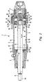
- the illustrated in the drawing fluid actuated working cylinder 1 has an elongated cylinder housing 2, which is composed of a cylinder tube 3 and two frontally sealingly fixed thereon first and second end caps 4, 5.
- the receiving space 6 is peripherally bounded by the cylinder tube 3 and at its two end faces of the two end caps 4, 5.
- the piston 7 can perform in the receiving space 6 indicated by a double arrow linear motion 8, wherein it slides on the inner surface 12 of the cylinder tube 3 along, with which it is in sealing contact.
- the piston 7 is equipped with an annular seal 13.
- a piston rod 14 is fixedly connected, which extends coaxially with the cylinder housing 2 and the second end cover 5 passes under sealing and at the same time displaceably guided.
- the end portion of the piston rod 14 located outside the cylinder housing 2 has fastening means 15 for attaching a component to be moved, for example a component of a machine.
- the piston 7 divides the receiving space 6 into a first and a second working chamber 15, 16. Each working space communicates with the associated end cap 4, 5 passing through the fluid channel 17 through which a pressurized fluid can be supplied and removed. By controlled fluid admission of the two working chambers 15, 16, the piston 7 and thus also the piston rod 14 connected thereto can be driven to the linear movement 8. Thereby, the piston 7 between two dash-dotted lines indicated first and second end positions 18, 19 are moved. In the respective end position 18, 19 of the piston 14 is located on a facing end surface 22 of the associated end cap 4, 5 at.
- FIG. 2 shows the piston 7 in a snapshot of the linear movement 8, wherein it is approaching the first end position 18 in the region of the first end cover 4.
- rubber-elastic buffer means 23 can be provided on the piston 7 and / or on the end faces 22 of the end covers 4, 5.
- the working cylinder 1 there is also the apparent from the drawing possibility to equip the working cylinder 1 with means for fluidic cushioning.
- These preferably contain two arranged in coaxial extension of the piston 7 and with this motion-coupled damping piston 24 smaller cross-section, which dive when approaching the respective end position in a recess 25 of the end cover 4, 5 and by simultaneous interaction with a sealing ring 26 the usual outflow for the shut off displaced fluid, so that it can only flow out via a throttle connected in parallel, which results in a deceleration of the piston speed.
- the throttle not shown in the drawing is usually housed in a recess 27 of the respective end cover 4, 5.
- the cylinder tube 3 is inserted with its two end portions 28, 29 in the respectively associated end cover 4, 5.
- Each end cover 4, 5 has an annular, and preferably sleeve-like cover extension 32, which protrudes axially beyond the end surface 22 and the outer end of the inserted end portion 28, coaxially overlaps and surrounds. This has the consequence that the piston 7 when reaching one of its end positions in the cover extension 32 of the associated end cap 4, 5 dives, the constellation in the embodiment is such that the piston located in an end position 7 over its entire length of the cover extension 32 is overlapped coaxially.
- a gas-tight welded connection is provided in each case.
- both the cylinder tube 3 and the two end covers 4, 5 are made entirely of plastic material, in particular by friction welding or by ultrasonic welding.
- the joining region of the weld joint is inter alia in the transition region between the outer circumference of the cylinder tube 3 and the inner circumference of the cover extension 32 resting thereon.
- the use of a gas-tight welded connection has the advantage that it is possible to dispense with additional sealing elements.
- the three components of the cylinder housing 2 each consist of a single plastic material, incidentally, there is also the possibility of implementation of, for example, a plurality of plastic materials or a combination of plastic and at least one other material, such as metal.
- the running surface for the piston 7 could consist of an unreinforced plastic material layer, which is enclosed by a layer of, for example, fiber-reinforced plastic material, which provides the necessary strength.
- the working cylinder 1 is equipped with means which enable a detection of the two end positions 18, 19 of the piston 7.
- These detection means comprise at least one actuating element 33 arranged on the piston 7, which is preferably a permanent magnet, which is expediently annular and is fixed concentrically on the piston 7.
- the detection means include at least a sensor receptacle 34 arranged on the outer circumference of the cover extension 32 of a respective end cap 4, 5 and a position sensor 35 which can be fixed or fixed in particular in the respective sensor receptacle 34.
- only the sensor receptacle 34 arranged on the first end cap 4 is equipped with a position sensor 35, because for the particular application of the working cylinder 1 only the first end position 18 is to be detected.
- the respective sensor receptacle 34 is arranged outside on the respective cover extension 32 in such a way that it is traversed by the piston 7 immersed in the cover extension 32.
- the sensor receptacle 34 is therefore adjacent to an end position 18, 19 engaging piston 7 radially outward. This creates the possibility of optimally arranging a position sensor 35 in the immediate vicinity of the piston 7 engaging the end position so that reliable, precise detection of the piston end position is ensured.
- This detection is based on a non-contact detection principle.
- the position sensor 35 becomes activated by the magnetic field of the actuating element 33, resulting in a sensor signal results, which can be transmitted via a cable 36 or using another transmission technology to an electronic evaluation and control device, not shown.
- the position sensor can be designed for example as a Hall sensor or as a reed switch.
- the position sensor 35 has a housing body 37 in which a sensor element 38 activatable by the actuation element 33 is located.
- the position sensor 35 can then be fixed in particular in the sensor receptacle 34 such that the sensor element 38 is at least substantially radially opposite the actuation element 33 when the piston 7 is in the assigned end position.
- the sensor receptacle 34 is provided flush with the axially oriented end face 43 of the cover extension 32 on its front side 42 facing the axially opposite other end cover. Furthermore, it is provided in the embodiment that extends the sensor receptacle 34, starting from the end face 43 over the entire length of the cover extension 32, wherein it also protrudes a little way beyond the cover extension 32 and along the rear extension of the cover extension 32 main body 44 of the respective end cover 4, 5 extends.
- the sensor receptacle 34 may have a greater length than the associated position sensor 35, so that the latter are adjusted within a wide range in the desired position can and is always accommodated over its entire length within the sensor receptacle 34.
- the cylinder tube 3 can be realized with a geometrically very simple shape.
- a cylinder tube 3 with outside oval or elliptical shape would be conceivable.
- the cylinder tube has a constant outer contour over its entire length.
- the sensor receptacle 34 is designed in the form of a channel 34a having a linear extension aligned in the longitudinal direction of the cylinder housing 2, in which the position sensor 35 can be inserted, in particular via the front side 42 and / or via the rear side 45.
- the wall thickness of the cover extension 32 can be kept as low as possible in the other areas
- the channel 34a is preferably in an integral part of the cover extension 32 forming rib-like elevation 46 on the outer circumference of the cover extension 32nd
- the channel 34a is designed as an longitudinal groove 47 which is remote from the cover extension 32 and opens radially outward with respect to the longitudinal axis 50 of the cylinder housing 2.
- the longitudinal groove 47 has a groove neck 48 and a broader anchoring section 49 adjoining it in groove depth direction.
- the longitudinal groove 47 is open both on the front 42 and on the back 45 and also on the outside over its entire length.
- the position sensor 35 can optionally be installed from one of the two end faces of the longitudinal groove 47 ago. With appropriate shaping and installation through the Nuthals 48 through is possible.
- a fastening device 52 is provided which allows fixing of the position sensor 35 by clamping in the longitudinal groove 47.
- the fastening device 52 comprises a clamping plate 53, which is arranged pivotably in a transverse slot 51 of the housing body 37 and into which a clamping screw 54 is screwed, which passes through the housing body 37 in a recess 68 provided in the groove depth direction.
- a clamping screw 54 is screwed at the outer end of the clamping screw 54 .
- the clamping screw 54 can be screwed against the groove bottom 56, so that the Clamping plate 53 is pressed against the two transition stages between the Nuthals 48 and the anchoring portion 49. Thereby, the position sensor 35 is securely held without being subjected to excessive stress itself.
- clamping plate 53 is pivotable about the longitudinal axis of the clamping screw 54, it can be temporarily positioned so that the position sensor 35 can be installed or disassembled through the Nuthals 48.
- the position sensor 35 can be positioned axially in the longitudinal groove 47 as required with dissolved fastener 52 and then releasably clamp at the desired location, by operating the fastening device 52.
- the sensor receptacle 34 differs in the design of Figures 4 and 5 only in that at one end portion of the longitudinal groove 47, a stop 57 is arranged for the displaceable in the longitudinal groove 47 position sensor 35.
- the stop 57 may be a longitudinal groove 47 within the Nuthalses 48 spanning web.
- the stop 57 can be a certain position for the position sensor 35 to be fixed in the longitudinal groove 47 pretend.
- the position sensor 35 is simply pushed so far axially into the longitudinal groove 47 until it reaches the end face of the stop 57 to the plant. Subsequently, the fastening device 52 is activated.
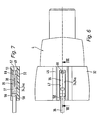
- FIGS. 6 and 7 a special fastening device 52 on the position sensor 35 is dispensed with. Compared with the designs of Figures 1 and 2 and 4 and 5 saves you thus the clamping screw 54 and the clamping plate 53rd
- the stop 57 already described is provided.
- latching projection 58 is provided at an axial distance from the stop 57, which is formed in the embodiment of a dome-like elevation of the groove bottom 56.
- the distance between the stop 57 and the locking projection 58 corresponds to the length of the position sensor 35.
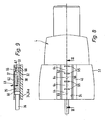
- FIGS. 8 and 9 show a variant of the sensor receptacle 34, in which the channel 34a on the outside facing away from the cover extension 32 is covered by a wall 62 integral with the end cover 4, 5.
- This wall 62 is divided longitudinally into a plurality of groove depth direction according to arrow 63 elastically deformable wall portions 64, wherein the subdivision is realized in the embodiment by axially spaced transverse slots 65.
- each elastically movable wall portion 64 is provided with first locking means 66 which are formed in the embodiment of punctiform, in particular wart-shaped elevations.
- second locking means 67 which are selectively engageable with each of the first locking means 66 in engagement and which are realized in the embodiment in the form of a recess of the housing body 37.
- the first latching means 66 protrude into the displacement path of the position sensor 35. If this is inserted axially into the channel 34a, the first latching means 66 acted upon by it are pressed outwards against the wall sections 64 carrying them against a resilient restoring force. During the insertion movement, the second latching means 67 pass successively the first latching means 66, which in each case first engage and then disengage. The position sensor 35 is inserted axially into the channel 34a until those first latching means 66 are engaged with the second latching means 67 which define the desired axial position of the position sensor 35.
- the position sensor via the latching means 66, 67 can be releasably set in different longitudinal positions in the sensor receptacle 34.
- the cylinder tube 3 is provided with both end portions in the manner according to the invention with a cover, it should be noted that such a cover can be provided on only one end portion of the cylinder tube 3, while at the other end of any other type of Attachment and design of a cover or end wall is provided.
Landscapes
- Engineering & Computer Science (AREA)
- Physics & Mathematics (AREA)
- Fluid Mechanics (AREA)
- Mechanical Engineering (AREA)
- General Engineering & Computer Science (AREA)
- Actuator (AREA)
Claims (22)
- Vérin à actionnement par un fluide, dont le boîtier de vérin (2) présente un tube de vérin (3) qui est enfoncé par au moins l'une de ses deux sections d'extrémité (28, 29) dans un couvercle de fermeture (4, 5), de sorte qu'il est saisi coaxialement sur sa circonférence extérieure par un prolongement de couvercle (32) de forme annulaire, dans lequel le piston (7) du vérin (1) peut s'enfoncer quand il atteint sa position d'extrémité, et avec au moins un logement de capteur (34) placé à l'extérieur sur le boîtier de vérin (2), logement qui est prévu pour la fixation d'un capteur de position (35) servant à détecter la position de fin de course du piston (7), caractérisé en ce que le logement de capteur (34) est placé de telle manière sur la circonférence extérieure du prolongement de couvercle (32) qu'il est sous-tendu par le piston (7) s'enfonçant dans le prolongement de boîtier (32), en étant formé par un canal (34a) présentant une extension linéaire, dans lequel le capteur de position (35) peut être ou est inséré.
- Vérin selon la revendication 1, caractérisé en ce que le logement de capteur (34) est placé au niveau de sa face antérieure (42) en affleurement avec la surface frontale (43) d'orientation axiale du prolongement de couvercle (32).
- Vérin selon la revendication 1 ou 2, caractérisé en ce que le logement de capteur (34) s'étend sur toute la longueur du prolongement de couvercle (32).
- Vérin selon l'une des revendications 1 à 3, caractérisé en ce que le logement de capteur (34) s'étend côté dos au moins sur une certaine distance le long de la partie principale (44) du couvercle de fermeture (4, 5) se raccordant au prolongement de couvercle (32).
- Vérin selon l'une des revendications 1 à 4, caractérisé en ce que le capteur de position installé (35) est logé entièrement à l'intérieur du logement de capteur (34).
- Vérin selon l'une des revendications 1 à 5, caractérisé en ce que le piston (7), quand il occupe sa position de fin de course (18, 19), vient se placer sur toute sa longueur dans le prolongement de couvercle (32).
- Vérin selon l'une des revendications 1 à 6, caractérisé en ce que le piston (7) est muni d'un élément d'actionnement (33) servant à activer le capteur de position (35) fixé dans le logement de capteur (34), en particulier un aimant permanent.
- Vérin selon l'une des revendications 1 à 7, caractérisé en ce que le tube de vérin (3) s'engage côté frontal dans une rainure annulaire (31) du couvercle de fermeture (4, 5) délimitée à l'extérieur radialement par le prolongement de couvercle (32).
- Vérin selon l'une des revendications 1 à 8, caractérisé en ce que le tube de vérin (3) possède sur toute sa longueur un contour extérieur constant.
- Vérin selon l'une des revendications 1 à 9, caractérisé en ce que le tube de vérin (3) est réalisé cylindrique à l'extérieur sur toute sa longueur, en particulier avec une forme cylindrique circulaire.
- Vérin selon l'une des revendications 1 à 10, caractérisé en ce que le tube de vérin (3) et/ou le couvercle de fermeture (4, 5) sont constitués entièrement ou partiellement en matière plastique.
- Vérin selon l'une des revendications 1 à 11, caractérisé par un capteur de position (35) fixé dans le logement de capteur (34), en particulier de manière amovible, par exemple sous la forme d'un capteur à effet Hall ou d'un commutateur de Reed.
- Vérin selon l'une des revendications 1 à 12, caractérisé en ce que le tube de vérin (3) est fixé avec ses deux sections d'extrémité (28, 29) à chaque fois dans un couvercle de fermeture (4, 5) du type prédéfini.
- Vérin selon l'une des revendications 1 à 13, caractérisé en ce que le couvercle de fermeture (4, 5) est relié de manière fixe au tube de vérin (3) par une soudure hermétique aux gaz, en particulier par une liaison soudée par friction ou une liaison soudée aux ultrasons.
- Vérin selon l'une des revendications 1 à 14, caractérisé en ce que le canal (34a) est réalisé dans une surélévation (46) de type nervure du couvercle de fermeture (4, 5).
- Vérin selon l'une des revendications 1 à 15, caractérisé en ce que le canal (34a) est recouvert sur sa face extérieure opposée au prolongement de couvercle (32) par une paroi (62) d'un seul tenant, qui est divisée en plusieurs sections de paroi (64) se succédant axialement et mobiles élastiquement de manière transversale à la direction longitudinale du canal qui, au niveau de la surface intérieure tournée vers le canal (34a), sont munies de premiers moyens d'encliquetage (66) qui peuvent être mis en prise séparable avec des deuxièmes moyens d'encliquetage (67) prévus sur le capteur de position (35), de telle manière que le capteur de position (35) peut être immobilisé par crans dans différentes positions longitudinales dans le logement de capteur (34).
- Vérin selon la revendication 16, caractérisé en ce que les sections de paroi élastiques (64) sont séparées les unes des autres par des fentes transversales (65).
- Vérin selon l'une des revendications 1 à 15, caractérisé en ce que le canal (34a) est conformé en rainure longitudinale (47) ouverte sur la face extérieure opposée au prolongement de couvercle (32), rainure qui dispose d'un col de rainure (48) et d'une section d'ancrage (49) plus large lui faisant suite dans la direction de la profondeur de la rainure et servant à l'ancrage du capteur de position (35).
- Vérin selon la revendication 18, caractérisé en ce que sur une section d'extrémité de la rainure longitudinale (47) est placée une butée (57) pour le capteur de position (35) pouvant être enfoncé dans la rainure longitudinale (47).
- Vérin selon la revendication 19, caractérisé en ce que la butée (57) est formée par une barrette recouvrant la rainure longitudinale (47).
- Vérin selon la revendication 19 ou 20, caractérisé en ce qu'à distance axiale de la butée (57), il est prévu au moins une saillie d'encliquetage (58) dépassant transversalement dans la rainure longitudinale (47), de telle manière que le capteur de position (35) installé est fixé de manière immobile axialement entre la butée (57) et la saillie d'encliquetage (58).
- Vérin selon l'une des revendications 18 à 21, caractérisé en ce que sur le capteur de position (35) est prévu un dispositif de fixation (52) pouvant être serré contre la surface intérieure de la rainure longitudinale (47).
Applications Claiming Priority (2)
| Application Number | Priority Date | Filing Date | Title |
|---|---|---|---|
| DE202004002852U | 2004-02-24 | ||
| DE200420002852 DE202004002852U1 (de) | 2004-02-24 | 2004-02-24 | Fluidbetätigter Arbeitszylinder |
Publications (3)
| Publication Number | Publication Date |
|---|---|
| EP1568894A2 EP1568894A2 (fr) | 2005-08-31 |
| EP1568894A3 EP1568894A3 (fr) | 2005-11-09 |
| EP1568894B1 true EP1568894B1 (fr) | 2007-04-11 |
Family
ID=32186299
Family Applications (1)
| Application Number | Title | Priority Date | Filing Date |
|---|---|---|---|
| EP05000205A Expired - Lifetime EP1568894B1 (fr) | 2004-02-24 | 2005-01-07 | Vérin à actionnement par fluide |
Country Status (2)
| Country | Link |
|---|---|
| EP (1) | EP1568894B1 (fr) |
| DE (2) | DE202004002852U1 (fr) |
Families Citing this family (4)
| Publication number | Priority date | Publication date | Assignee | Title |
|---|---|---|---|---|
| MX2009000805A (es) * | 2006-07-28 | 2009-02-03 | Norgren Gmbh | Porcion de piston para ensamble de piston y un ensamble de piston. |
| JP6098880B2 (ja) * | 2013-05-07 | 2017-03-22 | Smc株式会社 | 流体圧シリンダ |
| JP5854387B2 (ja) * | 2013-05-16 | 2016-02-09 | Smc株式会社 | 流体圧シリンダ |
| DE112014004317B4 (de) | 2013-09-19 | 2023-08-24 | Norgren Gmbh | Positionsüberwachungsgerät für einen Linearantrieb |
Family Cites Families (4)
| Publication number | Priority date | Publication date | Assignee | Title |
|---|---|---|---|---|
| FR2079871A5 (fr) * | 1970-02-16 | 1971-11-12 | Usinor | |
| DE3020390C2 (de) * | 1980-05-29 | 1983-03-24 | Festo-Maschinenfabrik Gottlieb Stoll, 7300 Esslingen | Arbeitszylinder |
| DE3734525A1 (de) * | 1987-10-13 | 1989-04-27 | Festo Kg | Insbesondere in abhaengigkeit von bestimmten kolbenstellungen eines kolben-zylinder-aggregates betaetigbare schaltanordnung |
| DE9207582U1 (de) * | 1992-06-04 | 1992-08-20 | Festo KG, 7300 Esslingen | Gehäuse für einen Arbeitszylinder |
-
2004
- 2004-02-24 DE DE200420002852 patent/DE202004002852U1/de not_active Expired - Lifetime
-
2005
- 2005-01-07 EP EP05000205A patent/EP1568894B1/fr not_active Expired - Lifetime
- 2005-01-07 DE DE200550000564 patent/DE502005000564D1/de not_active Expired - Lifetime
Non-Patent Citations (1)
| Title |
|---|
| None * |
Also Published As
| Publication number | Publication date |
|---|---|
| EP1568894A3 (fr) | 2005-11-09 |
| DE502005000564D1 (de) | 2007-05-24 |
| DE202004002852U1 (de) | 2004-04-22 |
| EP1568894A2 (fr) | 2005-08-31 |
Similar Documents
| Publication | Publication Date | Title |
|---|---|---|
| EP1369597B1 (fr) | Vérin hydraulique | |
| DE2404706C3 (de) | Hydropneumatischer Pralldämpfer | |
| EP0858762A1 (fr) | Tube d'aspiration téléscopique pour aspirateur | |
| EP2691658A1 (fr) | Entraînement à membrane actionné par fluide | |
| DE29607993U1 (de) | Kolben für einen Arbeitszylinder | |
| EP2228544A1 (fr) | Piston et dispositif actionné par fluide equipé avec ledit piston | |
| EP1512882B1 (fr) | Cylindre hydraulique | |
| DE19714646A1 (de) | Längenverstellbare Gasfeder | |
| DE19680491C5 (de) | Abdichtungen in einem Geberzylinder | |
| DE19516391B4 (de) | Zylinder für hydraulische Anlagen, insbesondere für Kraftfahrzeuge | |
| EP1568894B1 (fr) | Vérin à actionnement par fluide | |
| DE3113271C2 (fr) | ||
| EP1058037B1 (fr) | Piston pour un cylindre et son procédé de fabrication | |
| EP1978532B1 (fr) | Dispositif de réglage électromagnétique | |
| DE4134063A1 (de) | Linearantrieb | |
| DE19510528A1 (de) | Verstelleinrichtung | |
| DE202005013185U1 (de) | Kolben für einen Arbeitszylinder | |
| EP2047115B1 (fr) | Entraînement linéaire à commande fluidique | |
| DE8807543U1 (de) | Pneumatisches Stellelement | |
| EP0965779B1 (fr) | Anneau d'étanchéité | |
| EP1364129B1 (fr) | Entrainement lineaire sans tige de piston | |
| EP1426624B1 (fr) | Vérin linéaire sans tige | |
| DE3528123C1 (de) | Pneumatisches Stellelement für zentral verriegelbare Verschlüsse von Fahrzeugen | |
| DE19710574B4 (de) | Wegsensor | |
| DE3936411C1 (en) | Covering cap for axially movable switch rod - is of bellows-shaped elastometric material for sealing against dampness and dust |
Legal Events
| Date | Code | Title | Description |
|---|---|---|---|
| PUAI | Public reference made under article 153(3) epc to a published international application that has entered the european phase |
Free format text: ORIGINAL CODE: 0009012 |
|
| AK | Designated contracting states |
Kind code of ref document: A2 Designated state(s): AT BE BG CH CY CZ DE DK EE ES FI FR GB GR HU IE IS IT LI LT LU MC NL PL PT RO SE SI SK TR |
|
| AX | Request for extension of the european patent |
Extension state: AL BA HR LV MK YU |
|
| PUAL | Search report despatched |
Free format text: ORIGINAL CODE: 0009013 |
|
| AK | Designated contracting states |
Kind code of ref document: A3 Designated state(s): AT BE BG CH CY CZ DE DK EE ES FI FR GB GR HU IE IS IT LI LT LU MC NL PL PT RO SE SI SK TR |
|
| AX | Request for extension of the european patent |
Extension state: AL BA HR LV MK YU |
|
| 17P | Request for examination filed |
Effective date: 20060225 |
|
| AKX | Designation fees paid |
Designated state(s): DE FR GB IT |
|
| GRAP | Despatch of communication of intention to grant a patent |
Free format text: ORIGINAL CODE: EPIDOSNIGR1 |
|
| GRAS | Grant fee paid |
Free format text: ORIGINAL CODE: EPIDOSNIGR3 |
|
| GRAA | (expected) grant |
Free format text: ORIGINAL CODE: 0009210 |
|
| AK | Designated contracting states |
Kind code of ref document: B1 Designated state(s): DE FR GB IT |
|
| REG | Reference to a national code |
Ref country code: GB Ref legal event code: FG4D Free format text: NOT ENGLISH |
|
| GBT | Gb: translation of ep patent filed (gb section 77(6)(a)/1977) |
Effective date: 20070426 |
|
| REF | Corresponds to: |
Ref document number: 502005000564 Country of ref document: DE Date of ref document: 20070524 Kind code of ref document: P |
|
| ET | Fr: translation filed | ||
| PLBE | No opposition filed within time limit |
Free format text: ORIGINAL CODE: 0009261 |
|
| STAA | Information on the status of an ep patent application or granted ep patent |
Free format text: STATUS: NO OPPOSITION FILED WITHIN TIME LIMIT |
|
| 26N | No opposition filed |
Effective date: 20080114 |
|
| PGFP | Annual fee paid to national office [announced via postgrant information from national office to epo] |
Ref country code: GB Payment date: 20101220 Year of fee payment: 7 |
|
| PGFP | Annual fee paid to national office [announced via postgrant information from national office to epo] |
Ref country code: FR Payment date: 20120201 Year of fee payment: 8 |
|
| PGFP | Annual fee paid to national office [announced via postgrant information from national office to epo] |
Ref country code: IT Payment date: 20120118 Year of fee payment: 8 |
|
| PGFP | Annual fee paid to national office [announced via postgrant information from national office to epo] |
Ref country code: DE Payment date: 20121116 Year of fee payment: 9 |
|
| GBPC | Gb: european patent ceased through non-payment of renewal fee |
Effective date: 20130107 |
|
| REG | Reference to a national code |
Ref country code: FR Ref legal event code: ST Effective date: 20130930 |
|
| PG25 | Lapsed in a contracting state [announced via postgrant information from national office to epo] |
Ref country code: FR Free format text: LAPSE BECAUSE OF NON-PAYMENT OF DUE FEES Effective date: 20130131 Ref country code: GB Free format text: LAPSE BECAUSE OF NON-PAYMENT OF DUE FEES Effective date: 20130107 |
|
| PG25 | Lapsed in a contracting state [announced via postgrant information from national office to epo] |
Ref country code: IT Free format text: LAPSE BECAUSE OF NON-PAYMENT OF DUE FEES Effective date: 20130107 |
|
| REG | Reference to a national code |
Ref country code: DE Ref legal event code: R119 Ref document number: 502005000564 Country of ref document: DE |
|
| REG | Reference to a national code |
Ref country code: DE Ref legal event code: R119 Ref document number: 502005000564 Country of ref document: DE Effective date: 20140801 |
|
| PG25 | Lapsed in a contracting state [announced via postgrant information from national office to epo] |
Ref country code: DE Free format text: LAPSE BECAUSE OF NON-PAYMENT OF DUE FEES Effective date: 20140801 |